EP0240780A2 - Mixing valve air source - Google Patents
Mixing valve air source Download PDFInfo
- Publication number
- EP0240780A2 EP0240780A2 EP87103839A EP87103839A EP0240780A2 EP 0240780 A2 EP0240780 A2 EP 0240780A2 EP 87103839 A EP87103839 A EP 87103839A EP 87103839 A EP87103839 A EP 87103839A EP 0240780 A2 EP0240780 A2 EP 0240780A2
- Authority
- EP
- European Patent Office
- Prior art keywords
- temperature
- stream
- component
- control signal
- mixed stream
- Prior art date
- Legal status (The legal status is an assumption and is not a legal conclusion. Google has not performed a legal analysis and makes no representation as to the accuracy of the status listed.)
- Withdrawn
Links
Images

Classifications
-
- G—PHYSICS
- G05—CONTROLLING; REGULATING
- G05D—SYSTEMS FOR CONTROLLING OR REGULATING NON-ELECTRIC VARIABLES
- G05D23/00—Control of temperature
- G05D23/01—Control of temperature without auxiliary power
- G05D23/13—Control of temperature without auxiliary power by varying the mixing ratio of two fluids having different temperatures
- G05D23/138—Control of temperature without auxiliary power by varying the mixing ratio of two fluids having different temperatures for gases
-
- G—PHYSICS
- G05—CONTROLLING; REGULATING
- G05D—SYSTEMS FOR CONTROLLING OR REGULATING NON-ELECTRIC VARIABLES
- G05D23/00—Control of temperature
- G05D23/01—Control of temperature without auxiliary power
- G05D23/13—Control of temperature without auxiliary power by varying the mixing ratio of two fluids having different temperatures
- G05D23/1393—Control of temperature without auxiliary power by varying the mixing ratio of two fluids having different temperatures characterised by the use of electric means
Definitions
- the present invention relates generally to a system for and method of controlling the temperature of a pressurized fluid at a specific location and, more particularly, to a system for and method of controlling the temperature of a pressurized fluid at a specific test site by controlling the mix and temperature of hot and cold streams of the pressurized fluid in an economical and energy efficient manner.
- One type of currently marketed system cools the pressurized fluid to the lowest desired temperature, and subsequently reheats the fluid to the desired temperature.
- This type of system includes a single temperature sensor, located at the site of the object under test.
- a single temperature controller responsive to the single sensor raises or lowers the temperature of the fluid in order to bring and maintain the sensed temperature at the sensor location at the temperature set by the operator.
- the sensor must be at and the heater must be as close as possible to the test site to assure good temperature control and substantially reduce or eliminate temperature losses between the heater and test site.
- this approach is wasteful of energy since it is necessary to first cool the stream to the lowest temperature of the range and then reheat it.
- the approach is particularly wasteful of energy where the stream is recirculated in a closed loop configuration, i.e., the fluid stream is constantly recirculated through the test site. In the latter situation, the reheated fluid places unreasonable stress on any refrigeration system used by returning a high temperature fluid to the cooling section of the system. As a consequence, this approach requires a much larger refrigeration system than necessary for the designed thermal load in order to recool a returned high temperature fluid.
- Another type of system for controlling the temperature at a test site includes a heat source and heat sink for separately maintaining the temperature of first and second fluid streams at or near the respective highest and lowest temperatures of the desired range of temperatures, and a mixing valve for mixing the first and second fluid streams in a preselected ratio solely dependent on the temperature sensed by a sensor located at a preselected position within the system. If the sensor is located in the in the mixed stream just downstream from the mixing valve, a very precise valve control device is required to achieve good temperature control at the position of the sensor, but temperature losses between the sensor position and the test site are not compensated for at the test site. As a result, the actual temperature of the object under test may not be the same as the desired set temperature.
- the temperature control will be poor with a long temperature stabilization time required after each temperature change to damp out temperature oscillation at the test site.
- a system commercially available from the present assignee, Temptronic Corporation of Newton Massachusetts, is the Model 412, includes two sensors connected to a single controller, wherein one sensor is placed in the fluid stream, the other adjacent the object under test, for more accurately controlling the temperature of the object under test.
- This system is described in greater detail in U.S. Patent Application Serial No. 728,860 filed April 30, 1985 in the name of the present inventors, George Eager and Peter Selverstone, and assigned to the present assignee.
- a more specific object of the present invention is to provide a temperature controlled fluid stream system designed to substantially reduce the possible temperature transition times for the temperature at the test site to stabilize at a temperature set by the operator.
- Another object of the present invention is to provide an improved temperature controlled fluid stream system designed to control the temperature of the fluid stream at several locations of the stream.
- Yet another object of the present invention is to provide an improved temperature controlled fluid stream apparatus of the type including refrigeration and cooling systems, the apparatus being designed to reduce the thermal stress on the refrigeration system.
- Yet another object of the present invention is to provide a more energy efficient temperature controlled fluid stream system than provided by the prior art devices.
- Still another object of the present invention is to provide a temperature controlled fluid stream apparatus of the type including heating and cooling systems designed respectively to provide a heat output and refrigeration capacity tailored for more efficient operation than provided in the prior art devices.
- an improved system for precisely controlling the temperature at a predetermined location at a preselected temperature selected from a range of temperatures.
- the system comprises: means for generating a pressurized stream of fluid; means for separating said stream into first and second component streams; heating means responsive to a first control signal for heating said first component stream; cooling means for cooling said second component stream; mixer means for mixing said first and second component streams so as to provide a mixed stream; control means responsive to a second control signal for controlling the relative mix of said first and second component streams; means for carrying said mixed stream to said location; and signal generating means for generating said first and second control signals as a function of the preselected temperature, the temperature of said said first component stream downstream from said heater means, the temperature of said mixed stream and said temperature at said predetermined location.
- a method for precisely controlling the temperature at a predetermined location at a preselected temperature selected from a range of temperatures.
- the method comprises the steps of: generating a pressurized stream of fluid; separating said stream into first and second component streams; heating said first component stream in response to a first control signal; cooling said second component stream; mixing said first and second component streams so as to provide a mixed stream; controlling the relative mixing of said first and second component streams in response to a second control signal; carrying said mixed stream to said location; and generating said first and second control signals as a function of the preselected temperature, the temperature of said heated first component stream, the temperature of the mixed stream and said temperature at said predetermined location.
- the invention accordingly, comprises the processes involving the several steps and the relation and order of one or more of such steps with respect to each of the others, and the products possessing the features, properties and relation of components which are exemplified in the following detailed disclosure, and the scope of the application of which will be indicated in the claims.
- the apparatus 10 generally comprises the fluid flow system 20 for continuously delivering a stream of pressurized fluid to a test site 22.
- Apparatus 10 also includes cooling system 24 and the heater 38 for respectively cooling and heating the stream as needed in order to establish and maintain the level of the temperature at the site 24 to a temperature preset by the operator of the apparatus.
- a control system 26 is also provided for sensing the temperature at various points in the fluid flow system 20 and controlling the cooling system 24 and heater 38 so that the operator's preset temperature is established and maintained at site 22 in response to the various temperatures sensed.
- the fluid flow system 20 includes means, preferably in the form of a fan 30, for generating a stream of pressurized fluid, preferably air, at a flow rate, for example, of 30 cfm.
- the stream of air is directed through the fluid flow system 20 through an air conduit, generally indicated at 32.
- the system 20 is preferably a closed looped system so that the air is continuously recirculated therethrough.
- the air stream is directed from fan 30 through the air mixing valve 34.
- the latter is adapted to control the direction of air flow received from the fan 30 to the two conduit sections 32A and 32B.
- the sections 32A and 32B are respectively coupled to means, in the form of low temperature evaporator 36, for cooling the air stream provided in conduit section 32A, and means, in the form of heater 38, for heating the air stream provided in conduit section 32B.
- mixing valve 34 is designed to be positioned in a plurality of different positions and moved in response to and as a function of the electrical control signal received over the control line 128.
- the various positions of the valve are such that at one extreme postion substantially all of the air is directed through conduit section 32A and thus the evaporator 36. In this position a relatively small amount of air is provided to the section 32B and thus the heater 38 for reasons which will be more apparent hereinafter.
- Air mixing valves are well-known in the art, and thus valve 34 has not been described in greater detail.
- the valve is made of a low thermal mass material so that it will absorb little heat and offer little thermal resistance.
- the evaporator 36 also part of the cooling system 24, cools the air passing through section 32A.
- the evaporator is of a type well-known in the art and thus will not be described in detail.
- the evaporator is cooled by a low temperature refrigerant, such as those designated by the trade designations R13, R170 and R503 established by the American Society of Heating, Refrigeration and Air Conditioning Engineers (ASHRAE).
- the refrigerant is provided over the refrigerant line 44 of the cooling system 24, so that the air stream passing through the evaportor can be cooled to a temperature of about -70°C, although this can vary depending upon the application of the apparatus.
- Heater 38 can be any type of heater of well-known construction and providing sufficient output capacity (such as a resistance heater) for heating the air passing through the section 32B.
- the heater provides heat in response to the level of the power signal provided over power line 122 of the control system 26.
- the output of evaporator 36 and heater 38 are provided over the conduit sections 32C and 32D to the conduit junction 40 where the heated and cooled airstreams are fed into the conduit section 32E. The latter extends to test site 22.
- the test site 22 may be a sealed chamber or container, or may be the on site location of a system to be tested.
- the air is subsequently fed over line 32F to means, in the form of a high temperature evaporator 42, for precooling the air under certain prescribed conditions described hereinafter.
- a high temperature evaporator 42 for precooling the air under certain prescribed conditions described hereinafter.
- the air passing through evaporator 42 is cooled with a higher temperature refrigerant, such as those designated R12, R22 and R502 established by ASHRAE, provided over the refrigerant line 46 of cooling system 24.
- the airstream is returned through conduit section 32G to the fan 30.
- the cooling system 24 in the preferred embodiment is a two stage refrigerant system including the low temperature evaporator 36 and high temperature evaporator 42.
- the higher temperature refrigerant circulated in the refrigerant line 46 and used in evaporator 42 forms the high temperature stage of the cooling system, and is used to cool the lower temperature refrigerant circulated in the refrigerant line 44 (used in evaporator 36), the lower temperature refrigerant forming the low temperature stage of the system.
- the low temperature refrigerant stage includes a compressor 48 for condensing the low temperature refrigerant in line 44.
- the compressor 48 feeds the low temperature refrigerant through the condensor side of the interstage device 50.
- the refrigerant is then fed from the condensor 48 of the device 50 to the thermal expansion valve 52, which in turn is connected by the line 44 to the refrigerant input of evaporator 36.
- the thermal expansion valve 52 is of a type well-known in the art and generally controls the flow of the refrigerant as a function of the temperature of the refrigerant sensed by the sensor 54, disposed in the line 44 at the refrigerant output of the evaporator 36.
- the refrigerant will pass through the the expansion valve 52 in a liquid phase, enter the evaporator where it absorbs heat from the airstream and exit from the evaporator in a gas phase, where it will remain until compressed back to the liquid phase by the compressor 48.
- the sensor 54 controls the valve 52, which in turn controls the flow of the refrigerant to insure the proper amount of cooling is accomplished by the evaporator.
- the high temperature stage of the cooling system 24 includes the compressor 60 which pumps the refrigerant through the refrigerant line 46.
- the compressor forces the refrigerant through the condensor 62 for insuring the condensation of the refrigerant in line 46, from which it passes through the thermal expansion valve 64, through the evaporator side of the interstage device 50.
- the refrigerant passes from the evaporator side of the interstage device 50 through the sensor 66 for controlling the thermal expansion valve 64, back to the compressor 60.
- the valve 64 and sensor 66 operate in a manner identical to the valve 52 and sensor 54 for insuring that the evaporator side of the interstage device 50 is providing sufficient cooling to the refrigerant flowing through the condensor side of the device 50.
- the compressor also forces the high temperature refrigerant through the condensor 62 through the line 46 to the two selectively operable solenoid-operated valves 68 and 70 for controlling the amount of high temperature refrigerant flowing through the evaporator 42.
- the valves 68 and 70 are selectively open and closed in response to respective electrical signals provided over the electrical control lines 106 of the control system 26. Solenoid-activated valves 68 and 70 are operated in accordance with the following table:
- valve 68 The output of valve 68 is connected with the line 46 through thermal expansion valve 72 to the refrigerant input of the evaporator 42, while the valve 70 is connected through the capillary tube 74 to the refrigerant input of the evaporator 42.
- a sensor 76 at the refrigerant output of the evaporator 42 controls the expansion valve 72 in the same manner as sensors 54 and 66 control the valves 52 and 64, respectively, so as to insure that the evaporator 42 is properly cooling.
- the refrigerant passes from the sensor 76 through the evaporator pressure valve back to the input of the compressor.
- the compressor 60 thus pumps the refrigerant through two loops formed by the line 46, one through the evaporator 42 and the other through the evaporator side of the interstage device 50.
- control system 26 selectively controls the position of the mixing valve 34, the power level to the heater 38, and the operation of the solenoid valves 68 and 70 all for bringing the temperature to and maintaining the temperature of the test site 22 to the temperature set by the operator.
- Control system 26 preferably includes three sensors 90, 92 and 94 for respectively measuring the temperature of the airstream at three different locations.
- Sensor 90 is positioned at the site 22 for measuring the temperature of the airstream at that location, sensor 92 is positioned in conduit section 32D at the output of the heater 38 before junction 40 and sensor 94 is positioned in conduit section 32E sufficiently downstream from the junction 40 where the airstreams from the evaporator 36 and heater 38 are thoroughly mixed.
- Electrical input line 96 provides an electrical input signal representative of the temperature set by the operator.
- Line 96 is connected to the positive input of the summing junction 98.
- the negative input of junction 98 is connected to line 100, the latter being connected to transmit a signal from sensor 90 at site 22 representative of the temperature at the site.
- summing junction 98 (representative of the error E1 between the set point temperature T s and the site temperature T1 is provided to the logic unit 102 and the input of proportional integrator differentiator (PID) 104.
- PID proportional integrator differentiator
- Logic unit 102 also receives the signal from the sensor 90 over line 100.
- the logic unit 102 is connected so as to control the solenoid-operated switches 68 and 70 and thus the evaporator 42 in response to the site temperature sensed by sensor 90 and the error E1 generated by junction 98.
- the line 100 and the output of junction 98 are both connected to the inputs of logic unit 102, while the output of the latter is connected to the control lines 106.
- Logic unit 102 is designed to first assume that the evaporator 42 is operating in its low state, i.e., valve 68 is closed and valve 70 is open. Next, if E1 is less than -10°C, i.e. the measured temperature at the site is more than 10°C below the temperature set by the operator, the evaporator 42 is set to operate in its high state, i.e., solenoid valve 68 is open and valve 70 is closed.
- the evaporator 42 is set to the off state, i.e., the valves 68 and 70 are both closed preventing refrigerant from flowing through the evaporator 42.
- PID 104 provides an output signal K7 in accordance with the following:
- K7 new K7 old + (K1*E1+K2*D1)/256
- K7 new is the new value of K7; K7 old is the previous last value of K7; K1 is a constant; E1 is the current input signal from junction 98; K2 is a constant; and D1 is the difference between E1 (current) and the previous last value of E1.
- the output of PID 104 is connected to the positive input of the summing junction 108.
- the latter is adapted to receive at its negative input on line 110 a signal T2 from the sensor 94 positional in the mixed airstream in conduit section 32E representative of the temperature of the mixed airstream.
- the output of junction 108 (providing a signal E2 equal to K7 - T2) is applied to the input of PID 112 used for controlling the position of the mixing valve 34, and the input of PID 114 used for controlling the power delivered to heater 38 and also used to control the position of the mixing valve 34.
- PID 112 provides the output signal K6 derived from the following control function:
- X1 is a constant
- E2 is the current input signal from junction 108
- X2 is a constant
- D2 is the difference between E2 (current) and the previous last value of E2.
- PID 114 provides the output signal K6 derived from the following control function:
- K6 new is the new value of K6; K6 old is the previous last value of K6; K3 is a constant; E2 is the current input signal from junction 108; K4 is a constant; and D2 is the difference between E2 (current) and the previous last value of E2.
- the output of the PID 114 is the temperature set point for the heater 38.
- PID 114 can include means for setting the high and low limits of power delivered to the heater so that in the former case, the heater is prevented from getting too hot, and in the latter case, to allow a minimum amount of heat to the airstream passing through the heater to achieve better control and faster response times when the airstream must be heated.
- mixing valve 34 is constructed to always provide at least some minimum amount of air through the heater, as previously described.
- the output of PID 114 is connected to the positive input of the summing junction 116.
- the latter is adapted to receive a signal T3 over line 118 from the sensor 92 at the airstream output of the heater 38.
- the output signal of summing junction will, therefore, be the error signal E3 equal to the difference between the output signal K6 from PID 112 and the temperature signal T3.
- the output E3 of the junction 116 is connected to the input of PID 120 for providing the power signal P to the heater 38 over the power line 122 and for providing an input signal to the logic unit 124.
- PD 120 operates to carry out the following control function:
- P6 new is the new value of P6
- P6 old is the previous last value of P6
- K9 is a constant
- E3 is the current input signal from junction 108
- K10 is a constant
- D3 is the difference between E3 (current) and the previous last value of E3.
- the power level signal P is also applied to the input of the logic unit 124 for providing the current power level setting of the heater to the control loop for controling the position of the mixing valve 34.
- Unit 124 first determines the value of the variable P7 according to the following:
- the constant 50 is a constant chosen to represent a certain power level to the heater 38, e.g., 20% of maximum power. In this way, when the system demands a large amount of power to the heater 38 to raise the temperature of the airstream, a large amount, i.e., the value of P exceeds 100 (representive of 40% power) and P7 ⁇ -50, the value of P7 is set equal to -50, i.e., the power level is set at 40%.
- the P7/20 signal is applied to the negative input of the summing junction 126, the latter receiving at its positive input the output K8 of PID 112.
- the output of summing junction 126 (providing signal Z1) is connected to the control line 128, which in turn is connected to the mixing valve 34.
- the signal Z1 is equal to K8-P7/20 or:
- Unit 124 provides an output signal equal to P7/20.
- control system 26 including the junction 108, PD 114, junction 116, PID 120, heater 38 and two sensors 92 and 94, is similar to the control system used in the model 412 of the temperature controlled airstream system currently sold by Temptronic Corporation, the present assignee, and described in U.S. Patent application Serial No. 728,860, except that in the prior application one of the sensors is disposed in close proximity to the device under test, and thus the control functions of the PIDs are modified from those shown.
- the apparatus 10 provides control of the temperature at site 22 in an energy efficient manner by controlling the power provided over line 122 to heater 38, the control signal provided over the control line 128 for controlling the position of the mixing valve 34 so as to control the relative amounts of the airstream of the airstream provided to the low temperature evaporator 36 and the heater 38, and the control signals to the solenoid-operated valves 68 and 70 for controlling the state of the high temperature evaporator 42.
- the operator In order to operate the apparatus 10 the operator first turns on fan 30 so as to generate the airstream. Next the temperature T s is set by the operator. For illustrative purposes, assume that the site temperature is initially at room temperature, i.e., about +25°C, and that the operator has set the system to operate at +60°C. This will result in the output signal E1 of the summing junction 98 going positive to a level representative of +35°C.
- Logic unit 102 first assumes that the evaporator 42 is operating in its low state, i.e., valve 68 is closed and valve 70 is open. E1 (+35°C) is not less than -10°C. The temperature T1 (+60°C) measured by sensor 90 at site 22 is greater than -10°C. Logic 102, therefore, will generate the appropriate control signals to solenoid valves 68 and 70 so that the former is closed and the latter is open resulting in refrigerant being sent through the capillary tube 74 and then through the evaporator 42 so that the high temperature evaporator 42 operates in its low state and provides partial cooling.
- the output of PID 104, K7 will begin to increase so that the temperature of the airstream can be increased.
- E2 increasing from zero.
- An increase in E2 results in an increase to the PIDs 112 and 114.
- the latter provide an increasing signal K8 to the junction 126 and an increasing signal K6 resulting in an increasing temperature set point to the junction 116. Since the temperatures measured by sensors 92 and 94 are lower than indicated by the input temperature setting T s signal on line 96, the value E3 will be positive. The result will be increased power being delivered to the heater 38 and the mixing valve 34 adjusted so that a greater amount of the air stream being diverted through the heater 38 and less through the evaporator 36.
- All of the sensors 90, 92 and 94 will sense rising temperatures resulting in the values of E1, E2 and E3 diminishing.
- the derivative terms provided in PIDs 104, 112, 114 and 120 prevent unreasonable overshoot of the system, and the temperature at site 22 as sensed by the sensor 90 will stabilize at +60°C.
- the curve 2A represents the change in temperature of the mixed air as detected by the sensor 94, while the temperature of the airstream changes at the site 22 (as detected by sensor 90) as indicated by curve 2B.
- the overshoot shown by the portion of curve 2A rising above +60°C is a result of the derivative terms of the PIDs 104, 112, 114 and 124. The overshoot helps to raise the temperature at the site 22 more quickly to the +60°C level, providing a fast response time and conserving energy.
- PID 112 drives the output K8 down causing the mixing valve to be moved so as to increase the flow of the air stream through the evaporator 36 and decrease the flow through the heater 38.
- the negative E2 results in a negative E3 output of the junction 116 to the PID 120. The latter in turn results in a drop in power over line 122 to the heater 38 so as to reduce the amount of heat generated.
- E1 As the temperature at the site 22 drops from +60°C toward +25°C, when it reaches +35°C on its way to +25°C, the value of E1 will equal and then fall below -10°C difference between T s , the set temperature, and T1, the temperature of the airstream at site 22. As E1 falls below a -10°C error, the output of logic 102 will cause the evaporator to switch from the high state to the low state of operation. Thus, the solenoid-operated valve 68 will close and valve 70 will open causing the refrigerant to flow through the capillary tube 72 before flowing through the high temperature evaporator 42.
- the curve 3A represents the change in temperature of the mixed air as detected by the sensor 94, while the temperature of the airstream changes at the site 22 (as detected by sensor 90) as indicated by curve 3B.
- the overshoot shown by the portion of curve 3A dipping below 25°C is a result of the derivative terms of the PIDs 104, 112, 114 and 120. The overshoot helps to bring the temperature at the site 22 down more quickly to the 25°C level, providing a fast response time and conserving energy.
- control system 26 and the above-identified control functions of the logic units 102 and 124, and PIDs 104, 112, 114 and 124 are preferably performed by an external controller, such as a personal computer Model HP-85 manufactured by Hewlett Packard of California, as described in prior U.S. Patent Application Ser. No. 728,860 with a parallel interface bus, such as a IEEE-488 option, sold as the HPIB.
- the added external computer and IEEE-488 option provides both an external controller to vary the temperature set point provided on line 96, and readings of the temperatures sensed by sensors 90, 92 and 94.
- the apparatus 10 provides an improved system for establishing and maintaining the temperatures of an airstream at the site 22 with relative fast temperature transition times between the time the new temperature is set by the operator and the time the new temperature is reached and the system stabilized at the new temperature.
- the use of the three sensors 90, 92, and 94 provide better control of the temperature of the airstream.
- the use of logic unit 102 and the solenoid operated valves 68 and 70 to control the states of the high temperature evaporator 42 helps reduce the thermal stress on that evaporator.
- cooling system 24 has been shown as a two stage cooling system, the latter can be a single stage system or include three or more stages depending upon the requirements of the apparatus.
Abstract
Description
- The present invention relates generally to a system for and method of controlling the temperature of a pressurized fluid at a specific location and, more particularly, to a system for and method of controlling the temperature of a pressurized fluid at a specific test site by controlling the mix and temperature of hot and cold streams of the pressurized fluid in an economical and energy efficient manner.
- It is often important to test various objects (such as electrical component devices, e.g., wafers, integrated circuits, printed circuits, hybrid circuits, as well as small systems using such electrical component devices, e.g., pacemakers) at various temperatures throughout a range of temperatures, e.g., between about -70°C and 80°C. When conducting such tests it is important that the temperature at the site where the object is tested be as accurately controlled as possible in order to insure accurate testing results at the various test temperatures set by the operator.
- Various systems have been devised to carry out such tests. One type of currently marketed system cools the pressurized fluid to the lowest desired temperature, and subsequently reheats the fluid to the desired temperature. This type of system includes a single temperature sensor, located at the site of the object under test. A single temperature controller responsive to the single sensor raises or lowers the temperature of the fluid in order to bring and maintain the sensed temperature at the sensor location at the temperature set by the operator.
- The sensor must be at and the heater must be as close as possible to the test site to assure good temperature control and substantially reduce or eliminate temperature losses between the heater and test site. In addition, this approach is wasteful of energy since it is necessary to first cool the stream to the lowest temperature of the range and then reheat it. The approach is particularly wasteful of energy where the stream is recirculated in a closed loop configuration, i.e., the fluid stream is constantly recirculated through the test site. In the latter situation, the reheated fluid places unreasonable stress on any refrigeration system used by returning a high temperature fluid to the cooling section of the system. As a consequence, this approach requires a much larger refrigeration system than necessary for the designed thermal load in order to recool a returned high temperature fluid.
- Another type of system for controlling the temperature at a test site includes a heat source and heat sink for separately maintaining the temperature of first and second fluid streams at or near the respective highest and lowest temperatures of the desired range of temperatures, and a mixing valve for mixing the first and second fluid streams in a preselected ratio solely dependent on the temperature sensed by a sensor located at a preselected position within the system. If the sensor is located in the in the mixed stream just downstream from the mixing valve, a very precise valve control device is required to achieve good temperature control at the position of the sensor, but temperature losses between the sensor position and the test site are not compensated for at the test site. As a result, the actual temperature of the object under test may not be the same as the desired set temperature.
- If the sensor is placed at the test site the temperature control will be poor with a long temperature stabilization time required after each temperature change to damp out temperature oscillation at the test site.
- Recirculating the fluid stream of such a mixing valve system in a closed loop configuration results in the high temperature fluids returning from the test site stressing the refrigeration system unduly and requiring a relatively large capacity refrigeration system.
- An additional problem with these prior art systems is that the transition time necessary for the temperature to stabilize at the sensor site to the set temperature is relatively long. Further, the relatively large refrigeration and heater systems employed are relatively large energy consumption devices and thus are energy inefficient. As the high temperature fluid is returned from the test site it places a great deal of stress on the refrigeration system. With a single sensor and controller to control the temperature of the fluid stream, the system is capable of providing exact temperature control at the sensor site.
- A system, commercially available from the present assignee, Temptronic Corporation of Newton Massachusetts, is the Model 412, includes two sensors connected to a single controller, wherein one sensor is placed in the fluid stream, the other adjacent the object under test, for more accurately controlling the temperature of the object under test. This system is described in greater detail in U.S. Patent Application Serial No. 728,860 filed April 30, 1985 in the name of the present inventors, George Eager and Peter Selverstone, and assigned to the present assignee.
- It is a general object of the present invention to provide a temperature controlled fluid stream system designed to substantially reduce or overcome the above-noted disadvantages of the prior art.
- A more specific object of the present invention is to provide a temperature controlled fluid stream system designed to substantially reduce the possible temperature transition times for the temperature at the test site to stabilize at a temperature set by the operator.
- Another object of the present invention is to provide an improved temperature controlled fluid stream system designed to control the temperature of the fluid stream at several locations of the stream.
- And another object of the present invention is to provide an improved temperature controlled fluid stream apparatus of the type including refrigeration and cooling systems, the apparatus being designed to reduce the thermal stress on the refrigeration system.
- Yet another object of the present invention is to provide a more energy efficient temperature controlled fluid stream system than provided by the prior art devices.
- Still another object of the present invention is to provide a temperature controlled fluid stream apparatus of the type including heating and cooling systems designed respectively to provide a heat output and refrigeration capacity tailored for more efficient operation than provided in the prior art devices.
- These and other objects are achieved by an improved system for precisely controlling the temperature at a predetermined location at a preselected temperature selected from a range of temperatures. The system comprises:
means for generating a pressurized stream of fluid;
means for separating said stream into first and second component streams;
heating means responsive to a first control signal for heating said first component stream;
cooling means for cooling said second component stream;
mixer means for mixing said first and second component streams so as to provide a mixed stream;
control means responsive to a second control signal for controlling the relative mix of said first and second component streams;
means for carrying said mixed stream to said location; and
signal generating means for generating said first and second control signals as a function of the preselected temperature, the temperature of said said first component stream downstream from said heater means, the temperature of said mixed stream and said temperature at said predetermined location. - In accordance with another aspect of the present invention, a method is provided for precisely controlling the temperature at a predetermined location at a preselected temperature selected from a range of temperatures. The method comprises the steps of:
generating a pressurized stream of fluid;
separating said stream into first and second component streams;
heating said first component stream in response to a first control signal;
cooling said second component stream;
mixing said first and second component streams so as to provide a mixed stream;
controlling the relative mixing of said first and second component streams in response to a second control signal;
carrying said mixed stream to said location; and
generating said first and second control signals as a function of the preselected temperature, the temperature of said heated first component stream, the temperature of the mixed stream and said temperature at said predetermined location. - Other objects of the invention will in part be obvious and will in part appear hereinafter. The invention, accordingly, comprises the processes involving the several steps and the relation and order of one or more of such steps with respect to each of the others, and the products possessing the features, properties and relation of components which are exemplified in the following detailed disclosure, and the scope of the application of which will be indicated in the claims.
- For a fuller understanding of the nature and objects of the present invention, reference should be had to the following detailed description taken in connection with the accompanying drawing wherein:
- Fig. 1 is a partial block and partial schematic diagram of the preferred embodiment of the present invention;
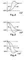
- Fig. 2 is a graphical illustration of an example of a typical response of the apparatus shown in Fig. 1;
- Fig. 3 is another graphical illustration of an example of another typical response of the apparatus shown in Fig. 1; and
- Fig. 4 is yet another graphical illustration of an example of another typical response of the apparatus shown in Fig. 1.
- Referring to Fig. 1, the
apparatus 10 generally comprises thefluid flow system 20 for continuously delivering a stream of pressurized fluid to atest site 22.Apparatus 10 also includescooling system 24 and theheater 38 for respectively cooling and heating the stream as needed in order to establish and maintain the level of the temperature at thesite 24 to a temperature preset by the operator of the apparatus. Acontrol system 26 is also provided for sensing the temperature at various points in thefluid flow system 20 and controlling thecooling system 24 andheater 38 so that the operator's preset temperature is established and maintained atsite 22 in response to the various temperatures sensed. - The
fluid flow system 20 includes means, preferably in the form of afan 30, for generating a stream of pressurized fluid, preferably air, at a flow rate, for example, of 30 cfm. The stream of air is directed through thefluid flow system 20 through an air conduit, generally indicated at 32. Thesystem 20 is preferably a closed looped system so that the air is continuously recirculated therethrough. The air stream is directed fromfan 30 through theair mixing valve 34. The latter is adapted to control the direction of air flow received from thefan 30 to the twoconduit sections 32A and 32B. Thesections 32A and 32B are respectively coupled to means, in the form oflow temperature evaporator 36, for cooling the air stream provided inconduit section 32A, and means, in the form ofheater 38, for heating the air stream provided in conduit section 32B. - More specifically,
mixing valve 34 is designed to be positioned in a plurality of different positions and moved in response to and as a function of the electrical control signal received over thecontrol line 128. The various positions of the valve are such that at one extreme postion substantially all of the air is directed throughconduit section 32A and thus theevaporator 36. In this position a relatively small amount of air is provided to the section 32B and thus theheater 38 for reasons which will be more apparent hereinafter. As the valve is moved toward its other extreme position, a greater proportion of the air is directed through the conduit section 32B and less throughconduit section 32A until the valve is positioned its other extreme position wherein all of the air is directed through the section 32B andheater 38 and none through thesection 32A andevaporator 36. Air mixing valves are well-known in the art, and thusvalve 34 has not been described in greater detail. Preferably, the valve is made of a low thermal mass material so that it will absorb little heat and offer little thermal resistance. - As will be more evident hereinafter, the
evaporator 36, also part of thecooling system 24, cools the air passing throughsection 32A. The evaporator is of a type well-known in the art and thus will not be described in detail. Preferably, the evaporator is cooled by a low temperature refrigerant, such as those designated by the trade designations R13, R170 and R503 established by the American Society of Heating, Refrigeration and Air Conditioning Engineers (ASHRAE). The refrigerant is provided over therefrigerant line 44 of thecooling system 24, so that the air stream passing through the evaportor can be cooled to a temperature of about -70°C, although this can vary depending upon the application of the apparatus.Heater 38 can be any type of heater of well-known construction and providing sufficient output capacity (such as a resistance heater) for heating the air passing through the section 32B. The heater provides heat in response to the level of the power signal provided overpower line 122 of thecontrol system 26. The output ofevaporator 36 andheater 38 are provided over theconduit sections conduit junction 40 where the heated and cooled airstreams are fed into theconduit section 32E. The latter extends to testsite 22. - The
test site 22 may be a sealed chamber or container, or may be the on site location of a system to be tested. - The air is subsequently fed over line 32F to means, in the form of a
high temperature evaporator 42, for precooling the air under certain prescribed conditions described hereinafter. Preferably, the air passing throughevaporator 42 is cooled with a higher temperature refrigerant, such as those designated R12, R22 and R502 established by ASHRAE, provided over therefrigerant line 46 ofcooling system 24. The airstream is returned throughconduit section 32G to thefan 30. - The
cooling system 24 in the preferred embodiment is a two stage refrigerant system including thelow temperature evaporator 36 andhigh temperature evaporator 42. Generally, in accordance with standard refrigeration techniques, the higher temperature refrigerant circulated in therefrigerant line 46 and used inevaporator 42 forms the high temperature stage of the cooling system, and is used to cool the lower temperature refrigerant circulated in the refrigerant line 44 (used in evaporator 36), the lower temperature refrigerant forming the low temperature stage of the system. - In accordance with certain aspects of the present invention, however, the circulation of the two refrigerants are controlled in a manner described in greater detail hereinafter. Generally, the low temperature refrigerant stage includes a
compressor 48 for condensing the low temperature refrigerant inline 44. Thecompressor 48 feeds the low temperature refrigerant through the condensor side of theinterstage device 50. The refrigerant is then fed from thecondensor 48 of thedevice 50 to thethermal expansion valve 52, which in turn is connected by theline 44 to the refrigerant input ofevaporator 36. Thethermal expansion valve 52 is of a type well-known in the art and generally controls the flow of the refrigerant as a function of the temperature of the refrigerant sensed by the sensor 54, disposed in theline 44 at the refrigerant output of theevaporator 36. When the system is operating, the refrigerant will pass through the theexpansion valve 52 in a liquid phase, enter the evaporator where it absorbs heat from the airstream and exit from the evaporator in a gas phase, where it will remain until compressed back to the liquid phase by thecompressor 48. The sensor 54 controls thevalve 52, which in turn controls the flow of the refrigerant to insure the proper amount of cooling is accomplished by the evaporator. - The high temperature stage of the
cooling system 24 includes thecompressor 60 which pumps the refrigerant through therefrigerant line 46. The compressor forces the refrigerant through thecondensor 62 for insuring the condensation of the refrigerant inline 46, from which it passes through thethermal expansion valve 64, through the evaporator side of theinterstage device 50. The refrigerant passes from the evaporator side of theinterstage device 50 through thesensor 66 for controlling thethermal expansion valve 64, back to thecompressor 60. Thevalve 64 andsensor 66 operate in a manner identical to thevalve 52 and sensor 54 for insuring that the evaporator side of theinterstage device 50 is providing sufficient cooling to the refrigerant flowing through the condensor side of thedevice 50. - The compressor also forces the high temperature refrigerant through the
condensor 62 through theline 46 to the two selectively operable solenoid-operatedvalves evaporator 42. Thevalves electrical control lines 106 of thecontrol system 26. Solenoid-activatedvalves 
- The output of
valve 68 is connected with theline 46 throughthermal expansion valve 72 to the refrigerant input of theevaporator 42, while thevalve 70 is connected through thecapillary tube 74 to the refrigerant input of theevaporator 42. Asensor 76 at the refrigerant output of theevaporator 42 controls theexpansion valve 72 in the same manner assensors 54 and 66 control thevalves evaporator 42 is properly cooling. The refrigerant passes from thesensor 76 through the evaporator pressure valve back to the input of the compressor. Thecompressor 60 thus pumps the refrigerant through two loops formed by theline 46, one through theevaporator 42 and the other through the evaporator side of theinterstage device 50. - Referring now to the
control system 26, the latter selectively controls the position of the mixingvalve 34, the power level to theheater 38, and the operation of thesolenoid valves test site 22 to the temperature set by the operator. -
Control system 26 preferably includes threesensors Sensor 90 is positioned at thesite 22 for measuring the temperature of the airstream at that location,sensor 92 is positioned inconduit section 32D at the output of theheater 38 beforejunction 40 andsensor 94 is positioned inconduit section 32E sufficiently downstream from thejunction 40 where the airstreams from theevaporator 36 andheater 38 are thoroughly mixed. -
Electrical input line 96 provides an electrical input signal representative of the temperature set by the operator.Line 96 is connected to the positive input of the summingjunction 98. The negative input ofjunction 98 is connected toline 100, the latter being connected to transmit a signal fromsensor 90 atsite 22 representative of the temperature at the site. - The output of summing junction 98 (representative of the error E1 between the set point temperature Ts and the site temperature T1 is provided to the logic unit 102 and the input of proportional integrator differentiator (PID) 104. Logic unit 102 also receives the signal from the
sensor 90 overline 100. - The logic unit 102 is connected so as to control the solenoid-operated
switches evaporator 42 in response to the site temperature sensed bysensor 90 and the error E1 generated byjunction 98. Specifically, theline 100 and the output ofjunction 98 are both connected to the inputs of logic unit 102, while the output of the latter is connected to the control lines 106. - Logic unit 102 is designed to first assume that the
evaporator 42 is operating in its low state, i.e.,valve 68 is closed andvalve 70 is open. Next, if E1 is less than -10°C, i.e. the measured temperature at the site is more than 10°C below the temperature set by the operator, theevaporator 42 is set to operate in its high state, i.e.,solenoid valve 68 is open andvalve 70 is closed. However, if the temperature T1 measured bysensor 90 atsite 22 is less than -10°C (indicating the site is too cold and, therefore, the use of the evaporator is unnecessary) theevaporator 42 is set to the off state, i.e., thevalves evaporator 42. -
PID 104 provides an output signal K7 in accordance with the following: - wherein K7new is the new value of K7;
K7old is the previous last value of K7;
K1 is a constant;
E1 is the current input signal fromjunction 98;
K2 is a constant; and
D1 is the difference between E1 (current) and the previous last value of E1. - The output of
PID 104 is connected to the positive input of the summingjunction 108. The latter is adapted to receive at its negative input on line 110 a signal T2 from thesensor 94 positional in the mixed airstream inconduit section 32E representative of the temperature of the mixed airstream. The output of junction 108 (providing a signal E2 equal to K7 - T2) is applied to the input ofPID 112 used for controlling the position of the mixingvalve 34, and the input ofPID 114 used for controlling the power delivered toheater 38 and also used to control the position of the mixingvalve 34. -
PID 112 provides the output signal K6 derived from the following control function: - wherein X1 is a constant;
E2 is the current input signal fromjunction 108;
X2 is a constant; and
D2 is the difference between E2 (current) and the previous last value of E2. -
PID 114 provides the output signal K6 derived from the following control function: - wherein K6new is the new value of K6;
K6old is the previous last value of K6;
K3 is a constant;
E2 is the current input signal fromjunction 108;
K4 is a constant; and
D2 is the difference between E2 (current) and the previous last value of E2. - It should be appreciated that the output of the
PID 114 is the temperature set point for theheater 38.PID 114 can include means for setting the high and low limits of power delivered to the heater so that in the former case, the heater is prevented from getting too hot, and in the latter case, to allow a minimum amount of heat to the airstream passing through the heater to achieve better control and faster response times when the airstream must be heated. In thisregard mixing valve 34 is constructed to always provide at least some minimum amount of air through the heater, as previously described. - The output of
PID 114 is connected to the positive input of the summingjunction 116. The latter is adapted to receive a signal T3 overline 118 from thesensor 92 at the airstream output of theheater 38. The output signal of summing junction will, therefore, be the error signal E3 equal to the difference between the output signal K6 fromPID 112 and the temperature signal T3. The output E3 of thejunction 116 is connected to the input ofPID 120 for providing the power signal P to theheater 38 over thepower line 122 and for providing an input signal to thelogic unit 124.PD 120 operates to carry out the following control function: - wherein P6new is the new value of P6;
P6old is the previous last value of P6;
K9 is a constant;
E3 is the current input signal fromjunction 108;
K10 is a constant; and
D3 is the difference between E3 (current) and the previous last value of E3. - The power level signal P is also applied to the input of the
logic unit 124 for providing the current power level setting of the heater to the control loop for controling the position of the mixingvalve 34.Unit 124 first determines the value of the variable P7 according to the following: - The constant 50 is a constant chosen to represent a certain power level to the
heater 38, e.g., 20% of maximum power. In this way, when the system demands a large amount of power to theheater 38 to raise the temperature of the airstream, a large amount, i.e., the value of P exceeds 100 (representive of 40% power) and P7<-50, the value of P7 is set equal to -50, i.e., the power level is set at 40%. The P7/20 signal is applied to the negative input of the summingjunction 126, the latter receiving at its positive input the output K8 ofPID 112. - The output of summing junction 126 (providing signal Z1) is connected to the
control line 128, which in turn is connected to the mixingvalve 34. As will be evident from the foregoing, the signal Z1 is equal to K8-P7/20 or: - It will be appreciated that when the power signal P is large so that P7 = -50 (the power demanded for the
heater 38 is greater that 40%), the signal Z1 online 128 is allowed to change so that the mixingvalve 34 causes more of the airstream to flow though theheater 38 and less through theevaporator 36. This results in the mixture of air passing through thesection 32E to increase in temperature not only because of theheater 38, but also because a relatively greater amount of the airstream flows through the heater. This feature will conserve power while achieving a fast response.Unit 124 provides an output signal equal to P7/20. - It should be appreciated that the portion of the
control system 26, including thejunction 108,PD 114,junction 116,PID 120,heater 38 and twosensors - In operation, the
apparatus 10 provides control of the temperature atsite 22 in an energy efficient manner by controlling the power provided overline 122 toheater 38, the control signal provided over thecontrol line 128 for controlling the position of the mixingvalve 34 so as to control the relative amounts of the airstream of the airstream provided to thelow temperature evaporator 36 and theheater 38, and the control signals to the solenoid-operatedvalves high temperature evaporator 42. - In order to operate the
apparatus 10 the operator first turns onfan 30 so as to generate the airstream. Next the temperature Ts is set by the operator. For illustrative purposes, assume that the site temperature is initially at room temperature, i.e., about +25°C, and that the operator has set the system to operate at +60°C. This will result in the output signal E1 of the summingjunction 98 going positive to a level representative of +35°C. - Logic unit 102 first assumes that the
evaporator 42 is operating in its low state, i.e.,valve 68 is closed andvalve 70 is open. E1 (+35°C) is not less than -10°C. The temperature T1 (+60°C) measured bysensor 90 atsite 22 is greater than -10°C. Logic 102, therefore, will generate the appropriate control signals tosolenoid valves capillary tube 74 and then through theevaporator 42 so that thehigh temperature evaporator 42 operates in its low state and provides partial cooling. - The output of
PID 104, K7, will begin to increase so that the temperature of the airstream can be increased. This results in E2 increasing from zero. An increase in E2 results in an increase to thePIDs junction 126 and an increasing signal K6 resulting in an increasing temperature set point to thejunction 116. Since the temperatures measured bysensors line 96, the value E3 will be positive. The result will be increased power being delivered to theheater 38 and the mixingvalve 34 adjusted so that a greater amount of the air stream being diverted through theheater 38 and less through theevaporator 36. - All of the
sensors PIDs site 22 as sensed by thesensor 90 will stabilize at +60°C. - As shown in Fig. 2, the
curve 2A represents the change in temperature of the mixed air as detected by thesensor 94, while the temperature of the airstream changes at the site 22 (as detected by sensor 90) as indicated by curve 2B. The overshoot shown by the portion ofcurve 2A rising above +60°C is a result of the derivative terms of thePIDs site 22 more quickly to the +60°C level, providing a fast response time and conserving energy. - Next, assume that the temperature is reduced by the operator from +60°C to +25°C. This results in the value of E1 = +25°C - (+60°C) = -35°C. Since E1<-10°C, the condition exists for setting the
high temperature evaporator 42 in its high state. Accordingly, the logic 102 provides the necessary control signals overline 106 to the solenoid-actuatedvalves valve 68 is open andvalve 70 is closed. This results in the high temperature refrigerant flowing throughexpansion valve 72 andevaporator 42 to provide maximum use of the evaporator. Since E1 is negative, K7 is reduced, resulting in E2 going negative.PID 112 drives the output K8 down causing the mixing valve to be moved so as to increase the flow of the air stream through theevaporator 36 and decrease the flow through theheater 38. In addition, the negative E2 results in a negative E3 output of thejunction 116 to thePID 120. The latter in turn results in a drop in power overline 122 to theheater 38 so as to reduce the amount of heat generated. - As the temperature at the
site 22 drops from +60°C toward +25°C, when it reaches +35°C on its way to +25°C, the value of E1 will equal and then fall below -10°C difference between Ts, the set temperature, and T1, the temperature of the airstream atsite 22. As E1 falls below a -10°C error, the output of logic 102 will cause the evaporator to switch from the high state to the low state of operation. Thus, the solenoid-operatedvalve 68 will close andvalve 70 will open causing the refrigerant to flow through thecapillary tube 72 before flowing through thehigh temperature evaporator 42. - As shown in Fig. 3, the
curve 3A represents the change in temperature of the mixed air as detected by thesensor 94, while the temperature of the airstream changes at the site 22 (as detected by sensor 90) as indicated by curve 3B. The overshoot shown by the portion ofcurve 3A dipping below 25°C is a result of the derivative terms of thePIDs site 22 down more quickly to the 25°C level, providing a fast response time and conserving energy. - Finally, for illustration purpose, assume the system has stabilized at +25°C. The operator now sets the set temperature Ts to -50°C. This results in E1 dropping to a value representative of -50°C - (+25°C), or -75°C. Logic unit 102 will set the high temperature evaporator to a high state, wherein the solenoid- actuated
valve 68 will open and thevalve 70 will close resulting in the refrigerant flowing through thethermal expansion valve 72 prior to flowing though theevaporator 42. Since E1 equals -75°C, K7 will go down, resulting in E2 going negative. The values of K6 and K8 will go down resulting in the mixingvalve 34 being moved to allow more of the airstream through theevaporator 36 and less through theheater 38. As shown in Fig. 4, when the site temperature, as sensed bysensor 90, reaches -10°C, the logic unit 102 changes the state of thehigh temperature evaporator 42 from the high state to the off state, wherein both of the solenoid-actuatedvalves evaporator 42, which in turn could cause the refrigeration system to go into oscillation. As shown in Fig. 4, as in Figs. 2 and 3, the overshoot provided by the differentiators in thePIDs site 22 stabilizing at the -50°C set temperature relatively quickly. - The
control system 26 and the above-identified control functions of thelogic units 102 and 124, andPIDs line 96, and readings of the temperatures sensed bysensors - The
apparatus 10 provides an improved system for establishing and maintaining the temperatures of an airstream at thesite 22 with relative fast temperature transition times between the time the new temperature is set by the operator and the time the new temperature is reached and the system stabilized at the new temperature. The use of the threesensors valves high temperature evaporator 42 helps reduce the thermal stress on that evaporator. The provision of thecontrol system 26 for controlling the position of the mixingvalve 34 for determining the correct mix of the two airstreams flowing through thelow temperature evaporator 36 andheater 38, respectively, makes more efficient use of energy. Further, energy consumption is reduced using the mixing valve to cause proportionately more of the airstream to flow through theheater 38 than thelow temperature evaporator 36 when the power provided to theheater 38 exceeds a predetermined level, e.g., 40% of maximum of power. - Certain changes may be made in the above apparatus and processes without departing from the scope of the invention. For example, while the
cooling system 24 has been shown as a two stage cooling system, the latter can be a single stage system or include three or more stages depending upon the requirements of the apparatus. - Since certain other changes may be made in the above apparatus and processes, without departing from the scope of the invention herein involved, it is intended that all matter contained in the above description or shown in the accompanied drawing shall be interpreted in an illustrative and rot in a limiting sense.
Claims (18)
means for generating a pressurized stream of fluid;
means for separating said stream into first and second component streams;
heating means responsive to a first control signal for heating said first component stream;
cooling means for cooling said second component stream;
mixer means for mixing said first and second component streams so as to provide a mixed stream;
control means responsive to a second control signal for controlling the amount of mixing of said first and second component streams;
means for carrying said mixed stream to said location; and
signal generating means for generating said first and second control signals as a function of the preselected temperature, the temperature of said said first component stream downstream from said heater means, the temperature of said mixed stream and said temperature at said predetermined location.
generating a pressurized stream of fluid;
separating said stream into first and second component streams;
heating said first component stream in response to a first control signal;
cooling said second component stream;
mixing said first and second component streams so as to provide a mixed stream;
controlling the amount of mixing of said second and second component streams in response to a first control signal;
carrying said mixed stream to said location; and
generating said first and second control signals as a function of the preselected temperature, the temperature of said said heated first component stream, the temperature of the mixed stream and said temperature at said predetermined location.
Applications Claiming Priority (2)
| Application Number | Priority Date | Filing Date | Title |
|---|---|---|---|
| US06/849,532 US4784213A (en) | 1986-04-08 | 1986-04-08 | Mixing valve air source |
| US849532 | 1986-04-08 |
Publications (2)
| Publication Number | Publication Date |
|---|---|
| EP0240780A2 true EP0240780A2 (en) | 1987-10-14 |
| EP0240780A3 EP0240780A3 (en) | 1989-08-23 |
Family
ID=25305942
Family Applications (1)
| Application Number | Title | Priority Date | Filing Date |
|---|---|---|---|
| EP87103839A Withdrawn EP0240780A3 (en) | 1986-04-08 | 1987-03-17 | Mixing valve air source |
Country Status (3)
| Country | Link |
|---|---|
| US (1) | US4784213A (en) |
| EP (1) | EP0240780A3 (en) |
| JP (1) | JPS62248942A (en) |
Cited By (3)
| Publication number | Priority date | Publication date | Assignee | Title |
|---|---|---|---|---|
| US5006796A (en) * | 1987-10-28 | 1991-04-09 | Irish Transformers Limited | Temperature control instrument for electronic components under test |
| FR2669263A1 (en) * | 1990-11-21 | 1992-05-22 | Carboxyque Francaise | PROCESS AND INSTALLATION OF A GAS FLOW. |
| EP2980837A4 (en) * | 2013-03-25 | 2017-01-04 | Tokyo Electron Limited | Substrate testing apparatus and substrate temperature adjustment method |
Families Citing this family (39)
| Publication number | Priority date | Publication date | Assignee | Title |
|---|---|---|---|---|
| JPH0731208B2 (en) * | 1988-07-09 | 1995-04-10 | 株式会社日立製作所 | Reaction temperature controller for automatic analyzer |
| US5355938A (en) * | 1989-03-20 | 1994-10-18 | Toshiba Machine Co., Ltd. | Temperature control device |
| JP2937406B2 (en) * | 1990-04-26 | 1999-08-23 | 甲府日本電気株式会社 | Cooling system |
| JP2501244B2 (en) * | 1990-11-30 | 1996-05-29 | タバイエスペック株式会社 | Temperature control method |
| US5226472A (en) * | 1991-11-15 | 1993-07-13 | Lab-Line Instruments, Inc. | Modulated temperature control for environmental chamber |
| US5247989A (en) * | 1991-11-15 | 1993-09-28 | Lab-Line Instruments, Inc. | Modulated temperature control for environmental chamber |
| JPH05253790A (en) * | 1992-03-13 | 1993-10-05 | Toshiba Mach Co Ltd | Ultra-precision temperature control system for machine tool and control method thereof |
| JP3188363B2 (en) * | 1994-01-21 | 2001-07-16 | エフエスアイ・インターナショナル・インコーポレーテッド | Temperature controller using circulating coolant and temperature control method therefor |
| US5610529A (en) * | 1995-04-28 | 1997-03-11 | Cascade Microtech, Inc. | Probe station having conductive coating added to thermal chuck insulator |
| US5795784A (en) | 1996-09-19 | 1998-08-18 | Abbott Laboratories | Method of performing a process for determining an item of interest in a sample |
| US5856194A (en) | 1996-09-19 | 1999-01-05 | Abbott Laboratories | Method for determination of item of interest in a sample |
| US6476627B1 (en) | 1996-10-21 | 2002-11-05 | Delta Design, Inc. | Method and apparatus for temperature control of a device during testing |
| US6489793B2 (en) | 1996-10-21 | 2002-12-03 | Delta Design, Inc. | Temperature control of electronic devices using power following feedback |
| JP5000803B2 (en) | 1998-07-14 | 2012-08-15 | デルタ・デザイン・インコーポレイテッド | Apparatus and method for performing rapid response temperature repetitive control of electronic device over a wide range using liquid |
| US6445202B1 (en) | 1999-06-30 | 2002-09-03 | Cascade Microtech, Inc. | Probe station thermal chuck with shielding for capacitive current |
| US6189329B1 (en) * | 2000-04-04 | 2001-02-20 | Venturedyne Limited | Cascade refrigeration system |
| US7230764B2 (en) * | 2000-08-18 | 2007-06-12 | Reflexite Corporation | Differentially-cured materials and process for forming same |
| US6518782B1 (en) | 2000-08-29 | 2003-02-11 | Delta Design, Inc. | Active power monitoring using externally located current sensors |
| US6965226B2 (en) | 2000-09-05 | 2005-11-15 | Cascade Microtech, Inc. | Chuck for holding a device under test |
| US6914423B2 (en) | 2000-09-05 | 2005-07-05 | Cascade Microtech, Inc. | Probe station |
| US6771086B2 (en) * | 2002-02-19 | 2004-08-03 | Lucas/Signatone Corporation | Semiconductor wafer electrical testing with a mobile chiller plate for rapid and precise test temperature control |
| US6820598B2 (en) | 2002-03-22 | 2004-11-23 | Chrysalis Technologies Incorporated | Capillary fuel injector with metering valve for an internal combustion engine |
| US7357124B2 (en) * | 2002-05-10 | 2008-04-15 | Philip Morris Usa Inc. | Multiple capillary fuel injector for an internal combustion engine |
| US7492172B2 (en) | 2003-05-23 | 2009-02-17 | Cascade Microtech, Inc. | Chuck for holding a device under test |
| US20050067146A1 (en) * | 2003-09-02 | 2005-03-31 | Thayer John Gilbert | Two phase cooling system method for burn-in testing |
| US7129731B2 (en) * | 2003-09-02 | 2006-10-31 | Thermal Corp. | Heat pipe with chilled liquid condenser system for burn-in testing |
| US7013956B2 (en) * | 2003-09-02 | 2006-03-21 | Thermal Corp. | Heat pipe evaporator with porous valve |
| US20050067147A1 (en) * | 2003-09-02 | 2005-03-31 | Thayer John Gilbert | Loop thermosyphon for cooling semiconductors during burn-in testing |
| US7250626B2 (en) | 2003-10-22 | 2007-07-31 | Cascade Microtech, Inc. | Probe testing structure |
| US7187188B2 (en) | 2003-12-24 | 2007-03-06 | Cascade Microtech, Inc. | Chuck with integrated wafer support |
| US7337768B2 (en) * | 2004-05-07 | 2008-03-04 | Philip Morris Usa Inc. | Multiple capillary fuel injector for an internal combustion engine |
| US7656172B2 (en) | 2005-01-31 | 2010-02-02 | Cascade Microtech, Inc. | System for testing semiconductors |
| US7535247B2 (en) | 2005-01-31 | 2009-05-19 | Cascade Microtech, Inc. | Interface for testing semiconductors |
| US8151872B2 (en) * | 2007-03-16 | 2012-04-10 | Centipede Systems, Inc. | Method and apparatus for controlling temperature |
| US8319503B2 (en) | 2008-11-24 | 2012-11-27 | Cascade Microtech, Inc. | Test apparatus for measuring a characteristic of a device under test |
| EP2413045B1 (en) * | 2010-07-30 | 2014-02-26 | Grundfos Management A/S | Heat exchange unit |
| EP2413046B1 (en) * | 2010-07-30 | 2016-03-30 | Grundfos Management A/S | domestic water heating unit |
| FI126110B (en) * | 2011-01-19 | 2016-06-30 | Ouman Oy | Method, apparatus and computer software product for controlling actuators in temperature control |
| JP6105933B2 (en) * | 2012-12-28 | 2017-03-29 | 鹿島建設株式会社 | Air conditioner using direct expansion coil |
Citations (6)
| Publication number | Priority date | Publication date | Assignee | Title |
|---|---|---|---|---|
| US3343791A (en) * | 1965-05-24 | 1967-09-26 | Motorola Inc | Regulating system |
| US3785432A (en) * | 1972-10-02 | 1974-01-15 | Honeywell Inc | Electronic control circuit with time delay of main and feedback signals |
| US3788386A (en) * | 1971-11-30 | 1974-01-29 | Ranco Inc | Multiple zone air conditioning system |
| US3792400A (en) * | 1973-01-17 | 1974-02-12 | Johnson Service Co | Temperature responsive actuator |
| US3826963A (en) * | 1972-05-30 | 1974-07-30 | Ranco Inc | Damper actuator controls for air conditioning systems |
| US4734872A (en) * | 1985-04-30 | 1988-03-29 | Temptronic Corporation | Temperature control for device under test |
Family Cites Families (26)
| Publication number | Priority date | Publication date | Assignee | Title |
|---|---|---|---|---|
| US2788264A (en) * | 1953-05-25 | 1957-04-09 | Shell Dev | Apparatus for temperature control of chemical reaction vessels |
| US3274995A (en) * | 1963-07-09 | 1966-09-27 | Eidus William | Thermoelectric dental probe |
| US3729064A (en) * | 1968-06-03 | 1973-04-24 | New Britain Machine Co | Machine tool |
| US3618590A (en) * | 1969-06-27 | 1971-11-09 | Hoffmann La Roche | Thermal electric dental pulp tester |
| US3645697A (en) * | 1969-07-18 | 1972-02-29 | Phillips Petroleum Co | Controlling apparatus of a reactor |
| JPS5112270B1 (en) * | 1970-01-22 | 1976-04-17 | ||
| US3734081A (en) * | 1971-05-03 | 1973-05-22 | Schaack H Van | Tooth sensitivity testing method |
| US3841311A (en) * | 1972-03-15 | 1974-10-15 | R Brown | Dental pulp tester |
| US3782366A (en) * | 1972-03-15 | 1974-01-01 | R Brown | Dental pulp tester |
| DE2343910C3 (en) * | 1973-08-31 | 1979-02-15 | Draegerwerk Ag, 2400 Luebeck | Cryomedical facility |
| US3979671A (en) * | 1975-03-06 | 1976-09-07 | International Business Machines Corporation | Test fixture for use in a high speed electronic semiconductor chip test system |
| NL7610563A (en) * | 1976-09-22 | 1978-03-29 | Thorn Domestic Appliances Ltd | AIR DRYER. |
| US4102150A (en) * | 1976-11-01 | 1978-07-25 | Borg-Warner Corporation | Control system for refrigeration apparatus |
| US4164214A (en) * | 1977-07-25 | 1979-08-14 | The Regents Of The University Of California | Method and apparatus for measuring the sensitivity of teeth |
| US4215698A (en) * | 1978-06-08 | 1980-08-05 | Abcor, Inc. | Dental-caries detector |
| US4249899A (en) * | 1979-02-14 | 1981-02-10 | A-Dec, Inc. | Warm water dental syringe |
| US4308012A (en) * | 1980-01-21 | 1981-12-29 | Richard Tamler | Dental pulp vitality tester |
| US4286391A (en) * | 1980-02-11 | 1981-09-01 | General Electric Company | Control system for an automatic clothes dryer |
| US4308013A (en) * | 1980-06-19 | 1981-12-29 | Emery Major | Thermoelectric diagnostic instrument |
| US4381814A (en) * | 1980-10-01 | 1983-05-03 | Phillips Petroleum Company | Control of heat transfer from heat exchangers in parallel |
| US4426619A (en) * | 1981-06-03 | 1984-01-17 | Temptronic Corporation | Electrical testing system including plastic window test chamber and method of using same |
| US4350488A (en) * | 1981-06-29 | 1982-09-21 | Davis Laurance B | Dental pulp tester |
| EP0069592B1 (en) * | 1981-07-08 | 1985-04-24 | Fujitsu Limited | Device for testing semiconductor devices at a high temperature |
| US4397101A (en) * | 1981-09-10 | 1983-08-09 | General Electric Company | Automatic dryer control |
| IT1195211B (en) * | 1981-09-30 | 1988-10-12 | Cazzaniga Spa | METHOD AND EQUIPMENT FOR MEASUREMENT AND INDIRECT ACCOUNTING OF THERMAL ENERGY |
| US4484449A (en) * | 1983-02-15 | 1984-11-27 | Ernest Muench | Low temperature fail-safe cascade cooling apparatus |
-
1986
- 1986-04-08 US US06/849,532 patent/US4784213A/en not_active Expired - Lifetime
-
1987
- 1987-03-17 EP EP87103839A patent/EP0240780A3/en not_active Withdrawn
- 1987-04-08 JP JP62086740A patent/JPS62248942A/en active Granted
Patent Citations (6)
| Publication number | Priority date | Publication date | Assignee | Title |
|---|---|---|---|---|
| US3343791A (en) * | 1965-05-24 | 1967-09-26 | Motorola Inc | Regulating system |
| US3788386A (en) * | 1971-11-30 | 1974-01-29 | Ranco Inc | Multiple zone air conditioning system |
| US3826963A (en) * | 1972-05-30 | 1974-07-30 | Ranco Inc | Damper actuator controls for air conditioning systems |
| US3785432A (en) * | 1972-10-02 | 1974-01-15 | Honeywell Inc | Electronic control circuit with time delay of main and feedback signals |
| US3792400A (en) * | 1973-01-17 | 1974-02-12 | Johnson Service Co | Temperature responsive actuator |
| US4734872A (en) * | 1985-04-30 | 1988-03-29 | Temptronic Corporation | Temperature control for device under test |
Cited By (6)
| Publication number | Priority date | Publication date | Assignee | Title |
|---|---|---|---|---|
| US5006796A (en) * | 1987-10-28 | 1991-04-09 | Irish Transformers Limited | Temperature control instrument for electronic components under test |
| FR2669263A1 (en) * | 1990-11-21 | 1992-05-22 | Carboxyque Francaise | PROCESS AND INSTALLATION OF A GAS FLOW. |
| EP0487401A1 (en) * | 1990-11-21 | 1992-05-27 | Carboxyque Francaise | Method and arrangement for producing a gas flow |
| US5242664A (en) * | 1990-11-21 | 1993-09-07 | Fabien Willot | Process and apparatus for the preparation of a gas flow |
| EP2980837A4 (en) * | 2013-03-25 | 2017-01-04 | Tokyo Electron Limited | Substrate testing apparatus and substrate temperature adjustment method |
| US9885747B2 (en) | 2013-03-25 | 2018-02-06 | Tokyo Electron Limited | Substrate inspection apparatus and substrate temperature control method |
Also Published As
| Publication number | Publication date |
|---|---|
| JPH0320653B2 (en) | 1991-03-19 |
| EP0240780A3 (en) | 1989-08-23 |
| JPS62248942A (en) | 1987-10-29 |
| US4784213A (en) | 1988-11-15 |
Similar Documents
| Publication | Publication Date | Title |
|---|---|---|
| US4784213A (en) | Mixing valve air source | |
| US6802368B2 (en) | Temperature control system for a workpiece chuck | |
| CA1088183A (en) | Refrigerant charge adjuster apparatus | |
| US4265299A (en) | Heat pump control system | |
| US20070095097A1 (en) | Thermal control system and method | |
| EP2232230B1 (en) | Refrigeration system comprising a test chamber with temperature and humidity control | |
| US10030894B2 (en) | Air-conditioning apparatus | |
| WO1999034644A1 (en) | Power and control system for a workpiece chuck | |
| WO2014097282A2 (en) | Refrigerant charge assisting device, air-conditioning apparatus, and refrigerant charge assisting program | |
| US20090248212A1 (en) | Thermal control system and method | |
| CN102794206B (en) | Environmental test equipment with large-capacity refrigeration system and control method for environment test equipment | |
| CN112775715B (en) | Cooling device and cooling control method | |
| US11391497B2 (en) | Refrigeration apparatus and temperature control apparatus | |
| JPH04366341A (en) | Air conditioner | |
| CN115823787B (en) | Rapid and stable control method for room temperature between refrigeration systems | |
| CN107000535B (en) | For operating the method and apparatus for carrying out this method of the heat regulating device of motor vehicle interiors | |
| EP3812668A1 (en) | Cooling system with controlled biphase mixing of refrigerant and a method for cooling with the cooling system | |
| GB2589515A (en) | Air conditioning device | |
| CA1087707A (en) | Refrigerant charge adjuster apparatus | |
| US20230056446A1 (en) | A semiconductor wafer temperature control apparatus | |
| JPS63156976A (en) | Refrigeration cycle device | |
| TWI557386B (en) | A cooling system with a defrost function | |
| JPS62280557A (en) | Heat pump type air conditioner | |
| JPH0439584B2 (en) | ||
| JPH0439585B2 (en) |
Legal Events
| Date | Code | Title | Description |
|---|---|---|---|
| PUAI | Public reference made under article 153(3) epc to a published international application that has entered the european phase |
Free format text: ORIGINAL CODE: 0009012 |
|
| AK | Designated contracting states |
Kind code of ref document: A2 Designated state(s): DE FR GB |
|
| PUAL | Search report despatched |
Free format text: ORIGINAL CODE: 0009013 |
|
| AK | Designated contracting states |
Kind code of ref document: A3 Designated state(s): DE FR GB |
|
| 17P | Request for examination filed |
Effective date: 19900223 |
|
| 17Q | First examination report despatched |
Effective date: 19910729 |
|
| STAA | Information on the status of an ep patent application or granted ep patent |
Free format text: STATUS: THE APPLICATION IS DEEMED TO BE WITHDRAWN |
|
| 18D | Application deemed to be withdrawn |
Effective date: 19910901 |
|
| RIN1 | Information on inventor provided before grant (corrected) |
Inventor name: EAGER, GEORGE Inventor name: SCHEY, THOMAS J. Inventor name: SELVERSTONE, PETER |