EP0240888A2 - Color electrophotograhic method and apparatus - Google Patents
Color electrophotograhic method and apparatus Download PDFInfo
- Publication number
- EP0240888A2 EP0240888A2 EP87104662A EP87104662A EP0240888A2 EP 0240888 A2 EP0240888 A2 EP 0240888A2 EP 87104662 A EP87104662 A EP 87104662A EP 87104662 A EP87104662 A EP 87104662A EP 0240888 A2 EP0240888 A2 EP 0240888A2
- Authority
- EP
- European Patent Office
- Prior art keywords
- toner
- image
- images
- toner image
- color
- Prior art date
- Legal status (The legal status is an assumption and is not a legal conclusion. Google has not performed a legal analysis and makes no representation as to the accuracy of the status listed.)
- Granted
Links
Images


Classifications
-
- G—PHYSICS
- G03—PHOTOGRAPHY; CINEMATOGRAPHY; ANALOGOUS TECHNIQUES USING WAVES OTHER THAN OPTICAL WAVES; ELECTROGRAPHY; HOLOGRAPHY
- G03G—ELECTROGRAPHY; ELECTROPHOTOGRAPHY; MAGNETOGRAPHY
- G03G15/00—Apparatus for electrographic processes using a charge pattern
- G03G15/01—Apparatus for electrographic processes using a charge pattern for producing multicoloured copies
-
- G—PHYSICS
- G03—PHOTOGRAPHY; CINEMATOGRAPHY; ANALOGOUS TECHNIQUES USING WAVES OTHER THAN OPTICAL WAVES; ELECTROGRAPHY; HOLOGRAPHY
- G03G—ELECTROGRAPHY; ELECTROPHOTOGRAPHY; MAGNETOGRAPHY
- G03G13/00—Electrographic processes using a charge pattern
- G03G13/01—Electrographic processes using a charge pattern for multicoloured copies
Definitions
- the present invention relates to a color electrophotographic method and apparatus which can be applied to apparatus for producing hard copies of color images, such as color copiers, color printers and so forth. More specifically, the present invention is directed to a color electrophotographic method and apparatus in which a series of operations including steps for charging, exposure and development is conducted cyclically so as to form a plurality of toner images of different colors on an electrophotographic photosensitive medium (hereinafter referred to as a photosensitive medium) and these toner images are transferred in one step onto a sheet of paper.
- a photosensitive medium electrophotographic photosensitive medium
- Such a known color electrophotographic method (types of which are disclosed in, for example, the specifications of Japanese Patent Laid-Open No. 95456/l985 and U.S. Patent No. 4,599,285) has certain disadvantages in that the boundaries of images of different colors which are formed adjacent to each other may be blurred or the width of previously formed color image forming lines may be decreased when the next color image is formed, and that the particles of toner images may be scattered and the entirety of the images blurred when the electrostatic latent images on the photosensitive medium carrying the toner images are erased by irradiating light onto the photosensitive medium.
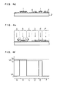
- Figs. 4a to 4f illustrate the process of forming second toner images on a photosensitive medium carrying first toner image that have been formed in the previous process.
- the photosensitive medium 2 which carries the first toner images l formed by a toner of an opaque color such as black is charged a second time to a surface potential of Vs by a corona charger 3 (Fig. 4a).
- a corona charger 3 a corona charger 3
- the areas D and F which are adjacent to the toner image on the area E are exposed (as shown by the arrows) (Fig. 4b) to form electrostatic latent images, so that the surface potential of these areas is attenuated to that of the residual potential (Vr) of the photosensitive medium (Fig. 4c).
- the present inventors have carried out intensive studies on the above-described problems, and have found that the scattering of toner particles occurs when the difference between the potentials of the toner image area and the adjacent areas reaches a certain value or above. It has also been found that the toner scattering which occurs when the electrostatic latent images are erased by light occurs to a greater extent as the opacity of the toner increases.
- an object of the present invention is to provide a color electrophotographic method and apparatus which is capable of clearly reproducing images of different colors which are formed adjacent to each other.
- Another object of this invention is to provide a color electrophotographic method and apparatus which ensures the formation of non-blurred and clear color images, and which can in particular provide such color images when employing toners of opaque colors.
- the above-mentioned objects are achieved by conducting exposure of a photosensitive medium to a second image signal with a non-image area formed on the boundary between a first toner image and the second latent image when the second image is formed adjacent to the first toner image.
- difference in potential between the toner image and the adjacent image can be eliminated, thereby preventing scattering of the toner particles and ensuring that the obtained color image is not blurred and the colors of which are clear and of high purity.
- Photosensitive mediums suitable for use in the present invention contain those of selenium, phthalocyanine, amorphous silicone and organic photoconductive material.
- Suitable light sources include a general lamp, a semiconductor laser, a gas laser of He-Ne or other gases, combination of liquid crystal switching elements and a lamp, and a light-emitting diode.
- Any toners which are employed in general electrophotography can be employed in the present invention as a developer, including non-magnetic or magnetic one-component toners or non-magnetic or magnetic two-component toners.
- non-magnetic toner having a resistivity of l010 ⁇ cm or above is preferable because it ensures that the colors are clear and of high purity.
- Any developing methods can be applied to the present invention, preferable methods including that which employs electric field forces for the photosensitive medium to attract the toner particles, that which employs gaseous discharge to generate a current of air for carrying the toner particles to the photosensitive medium, and a toner-cloud method which employs a mechanically generated air stream to carry the particles to the photosensitive medium.
- the most suitable one is the non-contact developing method of DC electric field type in which the toner particles are moved in one direction toward the photosensitive medium by virtue of forces of a DC electric field.
- Suitable developing devices are of a type in which the developing operation can be switched over between operating condition and non-operating condition.
- the photosensitive medium is positively charged and an image is formed through a negative-to-positive inversion.
- This principle is also applicable to image formation through a positive- to positive-process.
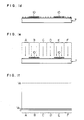
- a photosensitive medium 7 which is made of a conductive substrate 5 with a photosensitive layer 6 provided thereon is charged to an electric potential of Vs (between +700V and +l,200V) by a corona charger 8 (Fig. la), and a first exposure 9 is then conducted (Fig. lb) to form electrostatic latent images in such a manner that the difference between the surface potential Vr of the exposed portion (the areas B and E) and Vs is 500V or above (Fig. lc).
- the electrostatic latent images thus formed are inverted and developed by a first toner l0 of an opaque color such as black (Fig. ld).
- the entire surface of the photosensitive medium 7 is then irradiated with light to erase the electrostatic latent images (Fig. le).
- the erasure of the electrostatic latent images can be conducted in such a manner that the surface potential of the non-image portion (the areas A, C, D and F) is reduced to the residual potential Vr (0 to +l00V) of the photosensitive medium, as shown in Fig. lf, if the erasure is that of the electrostatic latent images formed on the photosensitive medium by the first exposure.
- the attenuation may of course be such that the difference in the potentials of the image portion and the non-image portion is 500V or less, as will be described later.
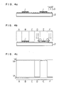
- the photosensitive medium 7 is again charged to Vs by the corona charger 8 (Fig. lg).
- these areas are exposed with minute gaps left at the edges thereof which are adjacent to the first toner image l0 (Fig. lh).
- Fig. li shows the potential of the photosensitive medium surface 7 after the second exposure. It is preferable that the width W of this minute gap is kept as small as possible. Although the desired value differs according to the potential of the electric charge applied to the surface of the photosensitive medium, the width W may be between 0.02 mm and 0.2 mm if the potential applied is l,200V or less. With such gaps formed adjacent to the edges of the areas D and F, the electric field strength generated at the edges of the toner image l0 by the second exposure decreases, and therefore no particles of the toner l0 are scattered.
- the electrostatic latent images formed in the second exposure are inverted and developed by a second toner l2 (Fig. lj), and the entire surface of the photosensitive medium 7 is then irradiated with light (Fig. lk) in such a manner that the difference between the surface potential of the areas A, C, D and F (that of the portion of the areas D and F which are exposed is Vr), Ve, and the surface potential of the areas B and E (which is slightly reduced to Vb by the light passing through the gaps formed between the toner particles, although the toner l0 itself does not transmit light, generally the difference in potentials between Vs and Vb being l00V or less.), Vb, becomes 500V or less, preferably, between l00V and 500V, as shown in Fig. ll.
- the difference in potential in this way, the electric field strength at the edges of the toner image l0 is lowered, thus preventing scattering of the toner l0.
- neutralization of the applied electric charge is performed by using light. However, this may also be done by employing AC corona discharge.
- Fig. 2 schematically shows a color printer which utilizes the color electrophotographic method of the present invention. It is to be noted that the arrangement of developing devices and the order of developments are not limited to those of this example.
- the color printer includes: an aluminum photosensitive drum l3 with selenium-tellurium deposited thereon, a corona charger l4; a light source l5 which is a combination of a light-emitting diode array having an output wavelength of 660 nm and a pixel density of l6 dot/mm and a self-focusing rod lens array; electric field attraction type developing devices which respectively contain the toners of yellow (Y), magenta (M), cyan (C) and black (BL) l6, l7, l8, l9; a charge eliminating lamp 20; a cleaning brush 2l; a transfer charger 22; a detach charger 23; and a paper sheet 24 onto which images are transferred.
- Y yellow
- M magenta
- C cyan
- BL black
- the developing devices l6, l7, l8, l9 are constructed basically in the same manner, and incorporate developing rollers 25, 26, 27, 28, respectively, for carrying a thin layer of toner.
- each of the developing devices has a toner container 29, toner particles 30 contained in the container, a cylindrical aluminum developing roller 3l, a conductive fur brush 32 which is an aluminum drum with a fur of rayon fibers with carbon dispersed therein planted thereon, the rayon fibers having a resistivity of l05 ⁇ cm, a rubber blade 33 for thinning a layer of toner uniformly on the developing roller, and a power source for controlling the amount of toner to be supplied onto the developing roller.
- the amount of toner supplied was adjusted such that thickness thereof on the developing roller 3l was between 20 and 50 ⁇ m by adjusting the pressing force of the rubber blade 33 and the voltage which was applied across the conductive fur brush 32 and the developing roller 3l.
- Each of the developing devices also has a mechanism for moving the developing device between a developing position which is 0.l to 0.2 mm away from the photosensitive drum l3 and a non-developing position which is 0.7 mm or more away therefrom.
- the toners of Y, M, C and Bl were a non-magnetic insulating toner the main components of which were resin and pigment.
- the mean particle diameter of each toner was l0 ⁇ m, while the allowance of electric charge and the resistivity were 2 - 5 ⁇ C/g and about l013 ⁇ cm, respectively.
- the surface of the photosensitive drum l3 was charged to a potential of +800V by the corona charger l4 (corona voltage: +7 kV) while it was rotated in the direction of an arrow.
- the photosensitive drum l3 was then scanning exposed to black image signals by the light source l5 to form negative electrostatic latent images.
- the potential on the non-image portion (non-exposed portion) was +800V, while that of the image portion (exposed-portion) was +50 V.
- the developing rollers, 25, 26, 27 of the respective developing devices l6, l7, l8 were grounded while a voltage of +750 V was applied to the developing roller 28 alone of the developing device l9, and the photosensitive drum l3 was made to pass by the developing devices so that the black toner images were formed on the photosensitive drum.
- the drum was then irradiated by the charge eliminating lamp 20 to reduce the potential of the surface of the non-image portion to +50 V.
- the photosensitive drum l3 carrying the black electrostatic latent images was charged to a second time by the corona charger l4 (corona voltage: +7 kV), and the drum was then scanning exposed to the yellow image signals by the light source l5.
- the photosensitive drum l3 was made to pass by the group of developing devices which were set in the following condition so as to form yellow toner images; a voltage of +750 V was applied to the developing roller 25 of the developing device l6 while the developing rollers of the other developing devices l7, l8 l9 were separated from the photosensitive drum through a distance of 0.7 mm or more to a non-developing position.
- the photosensitive drum was irradiated by the charge eliminating lamp 20 so as to reduce the potential of the non-image portion to +300 V.
- the surface potential of the portion onto which the black toner particles were attached was +760 V.
- the photosensitive drum l3 carrying the black and yellow toner images was charged a third time by the corona charger l4 (corona voltage: +7 kV), and the drum was then scanning exposed to the magenta image signals by the light source l5.
- the photosensitive drum l3 was made to pass by the group of developing devices which were set in the following condition so as to form magenta toner images; a voltage of +750 V was applied to the developing roller 26 of the developing device l7 while the developing rollers of other developing devices l6, l8, l9 were separated from the photosensitive drum l3 through a distance of 0.7 mm or more to a non-developing position.
- Light was then irradiated to the drum by the charge eliminating lamp 20 so as to reduce the potential of the non-image portion to +300 V.
- the potential of the portion onto which the black toner particles were attached was +760 V.
- the photosensitive drum l3 was charged a forth time by the corona charger l4 (corona voltage: +7 kV), and was then scanning exposed to the cyan image signals by the light source l5.
- the photosensitive drum l3 was made to pass by the group of developing devices which were set in the following condition so that the electrostatic latent images formed by the exposure were developed by the cyan toner; a voltage of +750 V was applied to the developing roller 27 of the developing device l8 alone while the developing rollers of other developing devices l6, l7, l9 were separated from the photosensitive drum l3 through a distance of 0.7 mm or more to a non-developing position.
- Light was then irradiated by the charge eliminating lamp 20 so as to reduce the potential of the non-image portion to +300 V.
- the potential of the portion onto which the black and cyan toner particles were attached was +760 V.
- the transfer paper sheet 24 After the color toner image thus formed on the photosensitive drum were transferred to the transfer paper sheet 24 by the transfer charger 22 which had a voltage of -5.5 kV, the charge on the transfer paper sheet 24 was neutralized by the detach charger 23 (removing voltage: ⁇ 7 kV) so as to separate the sheet from the photosensitive drum l3. The transfer paper sheet 24 carrying the color toner images was then thermally fixed to obtain a color print. After the transfer was completed, the toner particles left on the photosensitive drum l3 were cleaned by the cleaning brush 2l to get the drum ready for a subsequent image formation.
- the images of different colors were formed adjacent to one another by exposing the photosensitive drum to subsequent image signals with a gap of about 0.06 mm formed between the edges of the previously formed toner images and the subsequent image.
- This width corresponds to one scanning line of the light source.
- the quality of the obtained color print was a general resolution of l4 dots/mm and a background fog blurring occurred.
- a color print was obtained in the same manner as in the Example l with the exception that the potential of the surface of the non-image portion on which no toner particles were attached was attenuated to +50 V from +800 V when the surface charge was erased.
- the resultant color print had blurred black and cyan characters.
Abstract
Description
- The present invention relates to a color electrophotographic method and apparatus which can be applied to apparatus for producing hard copies of color images, such as color copiers, color printers and so forth. More specifically, the present invention is directed to a color electrophotographic method and apparatus in which a series of operations including steps for charging, exposure and development is conducted cyclically so as to form a plurality of toner images of different colors on an electrophotographic photosensitive medium (hereinafter referred to as a photosensitive medium) and these toner images are transferred in one step onto a sheet of paper.
- Such a known color electrophotographic method (types of which are disclosed in, for example, the specifications of Japanese Patent Laid-Open No. 95456/l985 and U.S. Patent No. 4,599,285) has certain disadvantages in that the boundaries of images of different colors which are formed adjacent to each other may be blurred or the width of previously formed color image forming lines may be decreased when the next color image is formed, and that the particles of toner images may be scattered and the entirety of the images blurred when the electrostatic latent images on the photosensitive medium carrying the toner images are erased by irradiating light onto the photosensitive medium.
- The disadvantages of the conventional apparatus to be overcome will be hereinunder described in detail by referring to Figs. 4a to 4f which illustrate the process of forming second toner images on a photosensitive medium carrying first toner image that have been formed in the previous process.
- The
photosensitive medium 2 which carries the first toner images l formed by a toner of an opaque color such as black is charged a second time to a surface potential of Vs by a corona charger 3 (Fig. 4a). Next, the areas D and F which are adjacent to the toner image on the area E are exposed (as shown by the arrows) (Fig. 4b) to form electrostatic latent images, so that the surface potential of these areas is attenuated to that of the residual potential (Vr) of the photosensitive medium (Fig. 4c). This generates large difference in the potentials at the boundaries between the area E and the areas D and F, and the toner particles located in the vicinity of the boundaries are thereby scattered along the lines of electric force which are directed toward the areas D and F from the edges of the area E, thus making the width of the toner image l smaller. - In consequence, when the electrostatic latent images are developed by a
second toner 4 of a color which is different from that of the first toner l (Fig. 4d), the color purity of the second toner images is degraded by the first toner particles l that have scattered to the vicinity of the boundaries of the area E. - Further, when light is irradiated over the entire surface of the photosensitive medium 2 (Fig. 4e) after the development by the
second toner 4 so as to attenuate the surface potential of thephotosensitive medium 2 at the areas on which no toner is attached (areas A and C and the edges of the area E) to Vr (Fig. 4f), the first toner particles located in the vinicity of the edges of the areas B and E are scattered to the areas A and C and the areas D and F, respectively, for the same reason as that described with reference to Fig. 4b, thereby blurring the images. At this time, the surface potential of thephotosensitive medium 2 under the first toner image l becomes Vb because it is slightly attenuated by the light passing through the gaps formed between toner particles, even though the toner itself does not transmit light. - The present inventors have carried out intensive studies on the above-described problems, and have found that the scattering of toner particles occurs when the difference between the potentials of the toner image area and the adjacent areas reaches a certain value or above. It has also been found that the toner scattering which occurs when the electrostatic latent images are erased by light occurs to a greater extent as the opacity of the toner increases.
- This invention has been developed for the purpose of obviating the above noted disadvantages of the prior art. Accordingly, an object of the present invention is to provide a color electrophotographic method and apparatus which is capable of clearly reproducing images of different colors which are formed adjacent to each other. Another object of this invention is to provide a color electrophotographic method and apparatus which ensures the formation of non-blurred and clear color images, and which can in particular provide such color images when employing toners of opaque colors.
- In the color electrophotographic method and apparatus of this invention in which a plurality of toner images of different colors are formed on a photosensitive medium by repetitions of a series of operations including the steps of charging, exposure and development the above-mentioned objects are achieved by conducting exposure of a photosensitive medium to a second image signal with a non-image area formed on the boundary between a first toner image and the second latent image when the second image is formed adjacent to the first toner image. As a result, difference in potential between the toner image and the adjacent image can be eliminated, thereby preventing scattering of the toner particles and ensuring that the obtained color image is not blurred and the colors of which are clear and of high purity.
-
- Figs. la to lℓ illustrate the principle of a color electrophotographic method according to the present invention;
- Fig. 2 schematically shows a color printer which utilizes the color electrophotographic method of the present invention;
- Fig. 3 is a schematic view of a developing device employed in the color printer of Fig. 2; and
- Figs. 4a to 4f illustrate the disadvantages of known color electrophotographic methods.
- Photosensitive mediums suitable for use in the present invention contain those of selenium, phthalocyanine, amorphous silicone and organic photoconductive material. Suitable light sources include a general lamp, a semiconductor laser, a gas laser of He-Ne or other gases, combination of liquid crystal switching elements and a lamp, and a light-emitting diode. Any toners which are employed in general electrophotography can be employed in the present invention as a developer, including non-magnetic or magnetic one-component toners or non-magnetic or magnetic two-component toners. For full color printing, however, non-magnetic toner having a resistivity of l0¹⁰ Ωcm or above is preferable because it ensures that the colors are clear and of high purity.
- Any developing methods can be applied to the present invention, preferable methods including that which employs electric field forces for the photosensitive medium to attract the toner particles, that which employs gaseous discharge to generate a current of air for carrying the toner particles to the photosensitive medium, and a toner-cloud method which employs a mechanically generated air stream to carry the particles to the photosensitive medium. The most suitable one is the non-contact developing method of DC electric field type in which the toner particles are moved in one direction toward the photosensitive medium by virtue of forces of a DC electric field. Suitable developing devices are of a type in which the developing operation can be switched over between operating condition and non-operating condition.
- The principle of the present invention will be described below by way of example by referring to Figs. la to lℓ. In the following example, the photosensitive medium is positively charged and an image is formed through a negative-to-positive inversion. This principle is also applicable to image formation through a positive- to positive-process.
- A photosensitive medium 7 which is made of a conductive substrate 5 with a photosensitive layer 6 provided thereon is charged to an electric potential of Vs (between +700V and +l,200V) by a corona charger 8 (Fig. la), and a first exposure 9 is then conducted (Fig. lb) to form electrostatic latent images in such a manner that the difference between the surface potential Vr of the exposed portion (the areas B and E) and Vs is 500V or above (Fig. lc).
- Subsequently, the electrostatic latent images thus formed are inverted and developed by a first toner l0 of an opaque color such as black (Fig. ld). The entire surface of the photosensitive medium 7 is then irradiated with light to erase the electrostatic latent images (Fig. le). The erasure of the electrostatic latent images can be conducted in such a manner that the surface potential of the non-image portion (the areas A, C, D and F) is reduced to the residual potential Vr (0 to +l00V) of the photosensitive medium, as shown in Fig. lf, if the erasure is that of the electrostatic latent images formed on the photosensitive medium by the first exposure. The attenuation may of course be such that the difference in the potentials of the image portion and the non-image portion is 500V or less, as will be described later.
- Next, the photosensitive medium 7 is again charged to Vs by the corona charger 8 (Fig. lg). In the subsequent exposure of the areas D and F which is conducted for forming second toner images adjacent to the first toner image l0, these areas are exposed with minute gaps left at the edges thereof which are adjacent to the first toner image l0 (Fig. lh). Fig. li shows the potential of the photosensitive medium surface 7 after the second exposure. It is preferable that the width W of this minute gap is kept as small as possible. Although the desired value differs according to the potential of the electric charge applied to the surface of the photosensitive medium, the width W may be between 0.02 mm and 0.2 mm if the potential applied is l,200V or less. With such gaps formed adjacent to the edges of the areas D and F, the electric field strength generated at the edges of the toner image l0 by the second exposure decreases, and therefore no particles of the toner l0 are scattered.
- Next, the electrostatic latent images formed in the second exposure are inverted and developed by a second toner l2 (Fig. lj), and the entire surface of the photosensitive medium 7 is then irradiated with light (Fig. lk) in such a manner that the difference between the surface potential of the areas A, C, D and F (that of the portion of the areas D and F which are exposed is Vr), Ve, and the surface potential of the areas B and E (which is slightly reduced to Vb by the light passing through the gaps formed between the toner particles, although the toner l0 itself does not transmit light, generally the difference in potentials between Vs and Vb being l00V or less.), Vb, becomes 500V or less, preferably, between l00V and 500V, as shown in Fig. ll. By adjusting the difference in potential in this way, the electric field strength at the edges of the toner image l0 is lowered, thus preventing scattering of the toner l0.
- This results in clear toner images wherein colors are not mixed at the boundaries between the first toner image l0 and the second toner images l2.
- In the example described above, neutralization of the applied electric charge is performed by using light. However, this may also be done by employing AC corona discharge.
- Fig. 2 schematically shows a color printer which utilizes the color electrophotographic method of the present invention. It is to be noted that the arrangement of developing devices and the order of developments are not limited to those of this example.
- The color printer includes: an aluminum photosensitive drum l3 with selenium-tellurium deposited thereon, a corona charger l4; a light source l5 which is a combination of a light-emitting diode array having an output wavelength of 660 nm and a pixel density of l6 dot/mm and a self-focusing rod lens array; electric field attraction type developing devices which respectively contain the toners of yellow (Y), magenta (M), cyan (C) and black (BL) l6, l7, l8, l9; a
charge eliminating lamp 20; a cleaning brush 2l; atransfer charger 22; a detachcharger 23; and apaper sheet 24 onto which images are transferred. - The developing devices l6, l7, l8, l9 are constructed basically in the same manner, and incorporate developing
rollers toner container 29,toner particles 30 contained in the container, a cylindrical aluminum developing roller 3l, aconductive fur brush 32 which is an aluminum drum with a fur of rayon fibers with carbon dispersed therein planted thereon, the rayon fibers having a resistivity of l0⁵ Ωcm, arubber blade 33 for thinning a layer of toner uniformly on the developing roller, and a power source for controlling the amount of toner to be supplied onto the developing roller. - In each developing device, the amount of toner supplied was adjusted such that thickness thereof on the developing roller 3l was between 20 and 50 µm by adjusting the pressing force of the
rubber blade 33 and the voltage which was applied across theconductive fur brush 32 and the developing roller 3l. - Each of the developing devices also has a mechanism for moving the developing device between a developing position which is 0.l to 0.2 mm away from the photosensitive drum l3 and a non-developing position which is 0.7 mm or more away therefrom.
- The toners of Y, M, C and Bl were a non-magnetic insulating toner the main components of which were resin and pigment. The mean particle diameter of each toner was l0 µm, while the allowance of electric charge and the resistivity were 2 - 5 µC/g and about l0¹³ Ωcm, respectively.
- Next, a method of forming color images with the apparatus described above will be described below.
- The surface of the photosensitive drum l3 was charged to a potential of +800V by the corona charger l4 (corona voltage: +7 kV) while it was rotated in the direction of an arrow. The photosensitive drum l3 was then scanning exposed to black image signals by the light source l5 to form negative electrostatic latent images. At this time, the potential on the non-image portion (non-exposed portion) was +800V, while that of the image portion (exposed-portion) was +50 V.
- After the exposure, the developing rollers, 25, 26, 27 of the respective developing devices l6, l7, l8 were grounded while a voltage of +750 V was applied to the developing
roller 28 alone of the developing device l9, and the photosensitive drum l3 was made to pass by the developing devices so that the black toner images were formed on the photosensitive drum. The drum was then irradiated by thecharge eliminating lamp 20 to reduce the potential of the surface of the non-image portion to +50 V. - Subsequently, the photosensitive drum l3 carrying the black electrostatic latent images was charged to a second time by the corona charger l4 (corona voltage: +7 kV), and the drum was then scanning exposed to the yellow image signals by the light source l5. After the exposure, the photosensitive drum l3 was made to pass by the group of developing devices which were set in the following condition so as to form yellow toner images; a voltage of +750 V was applied to the developing
roller 25 of the developing device l6 while the developing rollers of the other developing devices l7, l8 l9 were separated from the photosensitive drum through a distance of 0.7 mm or more to a non-developing position. Next, the photosensitive drum was irradiated by thecharge eliminating lamp 20 so as to reduce the potential of the non-image portion to +300 V. The surface potential of the portion onto which the black toner particles were attached was +760 V. - Subsequently, the photosensitive drum l3 carrying the black and yellow toner images was charged a third time by the corona charger l4 (corona voltage: +7 kV), and the drum was then scanning exposed to the magenta image signals by the light source l5. After the exposure, the photosensitive drum l3 was made to pass by the group of developing devices which were set in the following condition so as to form magenta toner images; a voltage of +750 V was applied to the developing
roller 26 of the developing device l7 while the developing rollers of other developing devices l6, l8, l9 were separated from the photosensitive drum l3 through a distance of 0.7 mm or more to a non-developing position. Light was then irradiated to the drum by thecharge eliminating lamp 20 so as to reduce the potential of the non-image portion to +300 V. The potential of the portion onto which the black toner particles were attached was +760 V. - Subsequently, the photosensitive drum l3 was charged a forth time by the corona charger l4 (corona voltage: +7 kV), and was then scanning exposed to the cyan image signals by the light source l5. After the exposure, the photosensitive drum l3 was made to pass by the group of developing devices which were set in the following condition so that the electrostatic latent images formed by the exposure were developed by the cyan toner; a voltage of +750 V was applied to the developing
roller 27 of the developing device l8 alone while the developing rollers of other developing devices l6, l7, l9 were separated from the photosensitive drum l3 through a distance of 0.7 mm or more to a non-developing position. Light was then irradiated by thecharge eliminating lamp 20 so as to reduce the potential of the non-image portion to +300 V. The potential of the portion onto which the black and cyan toner particles were attached was +760 V. - After the color toner image thus formed on the photosensitive drum were transferred to the
transfer paper sheet 24 by thetransfer charger 22 which had a voltage of -5.5 kV, the charge on thetransfer paper sheet 24 was neutralized by the detach charger 23 (removing voltage: ± 7 kV) so as to separate the sheet from the photosensitive drum l3. Thetransfer paper sheet 24 carrying the color toner images was then thermally fixed to obtain a color print. After the transfer was completed, the toner particles left on the photosensitive drum l3 were cleaned by the cleaning brush 2l to get the drum ready for a subsequent image formation. - By using the above-mentioned apparatus, the images of different colors were formed adjacent to one another by exposing the photosensitive drum to subsequent image signals with a gap of about 0.06 mm formed between the edges of the previously formed toner images and the subsequent image. This width corresponds to one scanning line of the light source. This provided a clear color print colors of which were not mixed at all at the boundaries of different colors. The non-image boundaries on which no development was conducted (which carry no images) were slightly narrowed through the processes of corona transfer of the toner images onto a transfer paper and thermal fixing, and were therefore practically not recognized.
- The quality of the obtained color print was a general resolution of l4 dots/mm and a background fog blurring occurred.
- A color print was obtained in the same manner as in the Example l with the exception that the potential of the surface of the non-image portion on which no toner particles were attached was attenuated to +50 V from +800 V when the surface charge was erased. The resultant color print had blurred black and cyan characters.
- As can be seen from the above description, according to the present invention, it is possible to reproduce clear images of different colors which are formed adjacent to each other. It is also possible to obtain a color print of high resolution on which the images of different colors are formed adjacent to each other without decrease in the width of the images, and the colors of which are not blurred.
Claims (8)
Applications Claiming Priority (6)
| Application Number | Priority Date | Filing Date | Title |
|---|---|---|---|
| JP61073558A JPS62231268A (en) | 1986-03-31 | 1986-03-31 | Color electrophotographic method |
| JP61073557A JPH0731439B2 (en) | 1986-03-31 | 1986-03-31 | Color-Electrophotographic method |
| JP73557/86 | 1986-03-31 | ||
| JP73558/86 | 1986-03-31 | ||
| JP105212/86 | 1986-05-08 | ||
| JP61105212A JP2537796B2 (en) | 1986-05-08 | 1986-05-08 | Color-Electrophotographic method |
Publications (3)
| Publication Number | Publication Date |
|---|---|
| EP0240888A2 true EP0240888A2 (en) | 1987-10-14 |
| EP0240888A3 EP0240888A3 (en) | 1988-10-19 |
| EP0240888B1 EP0240888B1 (en) | 1990-06-20 |
Family
ID=27301250
Family Applications (1)
| Application Number | Title | Priority Date | Filing Date |
|---|---|---|---|
| EP87104662A Expired - Lifetime EP0240888B1 (en) | 1986-03-31 | 1987-03-30 | Color electrophotograhic method and apparatus |
Country Status (4)
| Country | Link |
|---|---|
| US (1) | US4778740A (en) |
| EP (1) | EP0240888B1 (en) |
| KR (1) | KR910002442B1 (en) |
| DE (1) | DE3763342D1 (en) |
Cited By (4)
| Publication number | Priority date | Publication date | Assignee | Title |
|---|---|---|---|---|
| EP0314457A2 (en) * | 1987-10-27 | 1989-05-03 | Matsushita Electric Industrial Co., Ltd. | Method and apparatus for color electrophotography |
| EP0361851A1 (en) * | 1988-09-30 | 1990-04-04 | Xerox Corporation | Photoreceptor edge erase system especially for tri-level xerography |
| US5001028A (en) * | 1988-08-15 | 1991-03-19 | Eastman Kodak Company | Electrophotographic method using hard magnetic carrier particles |
| US5700611A (en) * | 1995-12-07 | 1997-12-23 | Eastman Kodak Company | Method for forming overlapping toner images |
Families Citing this family (9)
| Publication number | Priority date | Publication date | Assignee | Title |
|---|---|---|---|---|
| JPS62238585A (en) * | 1986-04-09 | 1987-10-19 | Asahi Optical Co Ltd | Multi-color image forming method for electrophotographic method |
| JPS63172285A (en) * | 1987-01-12 | 1988-07-15 | Minolta Camera Co Ltd | Electronic copying machine |
| US4921767A (en) * | 1988-12-21 | 1990-05-01 | Rca Licensing Corp. | Method of electrophotographically manufacturing a luminescent screen assembly for a cathode-ray-tube |
| US5388302A (en) * | 1993-01-08 | 1995-02-14 | Black & Decker Inc. | Vacuum cleaner housing and airflow chamber |
| US5394230A (en) * | 1993-05-20 | 1995-02-28 | Eastman Kodak Company | Method and apparatus for forming a composite dry toner image |
| US5985499A (en) * | 1993-05-20 | 1999-11-16 | Eastman Kodak Company | Method and apparatus for forming two toner images in a single frame |
| DE69404550T2 (en) * | 1993-05-20 | 1998-02-12 | Eastman Kodak Co | Method for producing two toner images one above the other |
| US5601909A (en) * | 1993-12-07 | 1997-02-11 | Kubo; Tetsujiro | Permanent electrode carrier using tourmaline |
| US5506668A (en) * | 1994-01-25 | 1996-04-09 | Eastman Kodak Company | Image forming apparatus having toner removing device |
Citations (3)
| Publication number | Priority date | Publication date | Assignee | Title |
|---|---|---|---|---|
| EP0143535A1 (en) * | 1983-10-03 | 1985-06-05 | Konica Corporation | Multiplex image reproducing method |
| JPS60143364A (en) * | 1983-12-30 | 1985-07-29 | Casio Comput Co Ltd | Two color image forming device |
| JPS60165670A (en) * | 1984-02-08 | 1985-08-28 | Fujitsu Ltd | Two color image recording method |
Family Cites Families (3)
| Publication number | Priority date | Publication date | Assignee | Title |
|---|---|---|---|---|
| US3615391A (en) * | 1967-05-22 | 1971-10-26 | Fuji Photo Film Co Ltd | Electrophotographic color developing method |
| US4039831A (en) * | 1975-10-15 | 1977-08-02 | Xerox Corporation | Two color xeroradiography development |
| US4634259A (en) * | 1983-12-13 | 1987-01-06 | Casio Computer Co., Ltd. | Apparatus for maintaining distinct edges between two colors in a two-color image forming device |
-
1987
- 1987-03-27 US US07/030,663 patent/US4778740A/en not_active Expired - Lifetime
- 1987-03-30 KR KR1019870002916A patent/KR910002442B1/en not_active IP Right Cessation
- 1987-03-30 DE DE8787104662T patent/DE3763342D1/en not_active Expired - Lifetime
- 1987-03-30 EP EP87104662A patent/EP0240888B1/en not_active Expired - Lifetime
Patent Citations (3)
| Publication number | Priority date | Publication date | Assignee | Title |
|---|---|---|---|---|
| EP0143535A1 (en) * | 1983-10-03 | 1985-06-05 | Konica Corporation | Multiplex image reproducing method |
| JPS60143364A (en) * | 1983-12-30 | 1985-07-29 | Casio Comput Co Ltd | Two color image forming device |
| JPS60165670A (en) * | 1984-02-08 | 1985-08-28 | Fujitsu Ltd | Two color image recording method |
Non-Patent Citations (2)
| Title |
|---|
| PATENT ABSTRACTS OF JAPAN, vol. 10, no. 9 (P-420)[2066], 14th January 1986; & JP-A-60 165 670 (FUJITSU K.K.) 28-08-1985 * |
| PATENT ABSTRACTS OF JAPAN, vol. 9, no. 314 (P-412)[2037], 10th December 1985; & JP-A-60 143 364 (CASIO KEISANKI K.K.) 29-07-1985 * |
Cited By (6)
| Publication number | Priority date | Publication date | Assignee | Title |
|---|---|---|---|---|
| EP0314457A2 (en) * | 1987-10-27 | 1989-05-03 | Matsushita Electric Industrial Co., Ltd. | Method and apparatus for color electrophotography |
| EP0314457A3 (en) * | 1987-10-27 | 1990-06-13 | Matsushita Electric Industrial Co., Ltd. | Method and apparatus for color electrophotography |
| US4949125A (en) * | 1987-10-27 | 1990-08-14 | Matsushita Electric Industrial Co., Ltd. | Method and apparatus for color electrophotography |
| US5001028A (en) * | 1988-08-15 | 1991-03-19 | Eastman Kodak Company | Electrophotographic method using hard magnetic carrier particles |
| EP0361851A1 (en) * | 1988-09-30 | 1990-04-04 | Xerox Corporation | Photoreceptor edge erase system especially for tri-level xerography |
| US5700611A (en) * | 1995-12-07 | 1997-12-23 | Eastman Kodak Company | Method for forming overlapping toner images |
Also Published As
| Publication number | Publication date |
|---|---|
| EP0240888A3 (en) | 1988-10-19 |
| KR910002442B1 (en) | 1991-04-22 |
| KR870009264A (en) | 1987-10-24 |
| DE3763342D1 (en) | 1990-07-26 |
| US4778740A (en) | 1988-10-18 |
| EP0240888B1 (en) | 1990-06-20 |
Similar Documents
| Publication | Publication Date | Title |
|---|---|---|
| US4761672A (en) | Ramped developer biases | |
| EP0240888B1 (en) | Color electrophotograhic method and apparatus | |
| US4809038A (en) | Color electrophotographic apparatus and method | |
| US4761668A (en) | Highlight color printer | |
| EP0340996B1 (en) | Tri-level, highlight color imaging using ionography | |
| JP2876902B2 (en) | Color electrophotographic equipment | |
| US4920024A (en) | Photoreceptor edge erase system for tri-level xerography | |
| JP2537783B2 (en) | Color-Electrophotographic method | |
| JP2537796B2 (en) | Color-Electrophotographic method | |
| JPS6064364A (en) | Method and device for image formation | |
| JP2604714B2 (en) | Color electrophotographic equipment | |
| JP2885521B2 (en) | Color electrophotographic equipment | |
| JPH0447314B2 (en) | ||
| JPH0731439B2 (en) | Color-Electrophotographic method | |
| JPH04158373A (en) | Color electrophotographing method | |
| JP3004063B2 (en) | Color electrophotographic equipment | |
| JP2574261B2 (en) | Color electrophotographic apparatus | |
| JPS6271969A (en) | Color electrophotographic method | |
| JPH083674B2 (en) | Color electrophotographic device | |
| JPS62231268A (en) | Color electrophotographic method | |
| JP2885522B2 (en) | Digital color electrophotographic equipment | |
| JPH083671B2 (en) | Color-Electrophotographic method | |
| JPS63139374A (en) | Color electrophotographing method | |
| JPS6063564A (en) | Image forming method and its device | |
| JPS62187377A (en) | Cleaning device |
Legal Events
| Date | Code | Title | Description |
|---|---|---|---|
| PUAI | Public reference made under article 153(3) epc to a published international application that has entered the european phase |
Free format text: ORIGINAL CODE: 0009012 |
|
| AK | Designated contracting states |
Kind code of ref document: A2 Designated state(s): DE FR GB |
|
| PUAL | Search report despatched |
Free format text: ORIGINAL CODE: 0009013 |
|
| AK | Designated contracting states |
Kind code of ref document: A3 Designated state(s): DE FR GB |
|
| 17P | Request for examination filed |
Effective date: 19881214 |
|
| 17Q | First examination report despatched |
Effective date: 19890505 |
|
| GRAA | (expected) grant |
Free format text: ORIGINAL CODE: 0009210 |
|
| AK | Designated contracting states |
Kind code of ref document: B1 Designated state(s): DE FR GB |
|
| REF | Corresponds to: |
Ref document number: 3763342 Country of ref document: DE Date of ref document: 19900726 |
|
| ET | Fr: translation filed | ||
| PLBE | No opposition filed within time limit |
Free format text: ORIGINAL CODE: 0009261 |
|
| STAA | Information on the status of an ep patent application or granted ep patent |
Free format text: STATUS: NO OPPOSITION FILED WITHIN TIME LIMIT |
|
| 26N | No opposition filed | ||
| REG | Reference to a national code |
Ref country code: GB Ref legal event code: 746 Effective date: 19950224 |
|
| REG | Reference to a national code |
Ref country code: FR Ref legal event code: D6 |
|
| REG | Reference to a national code |
Ref country code: GB Ref legal event code: IF02 |
|
| PGFP | Annual fee paid to national office [announced via postgrant information from national office to epo] |
Ref country code: DE Payment date: 20030409 Year of fee payment: 17 |
|
| PGFP | Annual fee paid to national office [announced via postgrant information from national office to epo] |
Ref country code: FR Payment date: 20040309 Year of fee payment: 18 |
|
| PGFP | Annual fee paid to national office [announced via postgrant information from national office to epo] |
Ref country code: GB Payment date: 20040324 Year of fee payment: 18 |
|
| PG25 | Lapsed in a contracting state [announced via postgrant information from national office to epo] |
Ref country code: DE Free format text: LAPSE BECAUSE OF NON-PAYMENT OF DUE FEES Effective date: 20041001 |
|
| PG25 | Lapsed in a contracting state [announced via postgrant information from national office to epo] |
Ref country code: GB Free format text: LAPSE BECAUSE OF NON-PAYMENT OF DUE FEES Effective date: 20050330 |
|
| GBPC | Gb: european patent ceased through non-payment of renewal fee |
Effective date: 20050330 |
|
| PG25 | Lapsed in a contracting state [announced via postgrant information from national office to epo] |
Ref country code: FR Free format text: LAPSE BECAUSE OF NON-PAYMENT OF DUE FEES Effective date: 20051130 |
|
| REG | Reference to a national code |
Ref country code: FR Ref legal event code: ST Effective date: 20051130 |