EP0247824B1 - Valve for medication infusion system - Google Patents
Valve for medication infusion system Download PDFInfo
- Publication number
- EP0247824B1 EP0247824B1 EP19870304641 EP87304641A EP0247824B1 EP 0247824 B1 EP0247824 B1 EP 0247824B1 EP 19870304641 EP19870304641 EP 19870304641 EP 87304641 A EP87304641 A EP 87304641A EP 0247824 B1 EP0247824 B1 EP 0247824B1
- Authority
- EP
- European Patent Office
- Prior art keywords
- valve
- valve disc
- valve assembly
- disc
- seal ring
- Prior art date
- Legal status (The legal status is an assumption and is not a legal conclusion. Google has not performed a legal analysis and makes no representation as to the accuracy of the status listed.)
- Expired - Lifetime
Links
Images


Classifications
-
- A—HUMAN NECESSITIES
- A61—MEDICAL OR VETERINARY SCIENCE; HYGIENE
- A61M—DEVICES FOR INTRODUCING MEDIA INTO, OR ONTO, THE BODY; DEVICES FOR TRANSDUCING BODY MEDIA OR FOR TAKING MEDIA FROM THE BODY; DEVICES FOR PRODUCING OR ENDING SLEEP OR STUPOR
- A61M39/00—Tubes, tube connectors, tube couplings, valves, access sites or the like, specially adapted for medical use
- A61M39/22—Valves or arrangement of valves
- A61M39/24—Check- or non-return valves
- A61M2039/242—Check- or non-return valves designed to open when a predetermined pressure or flow rate has been reached, e.g. check valve actuated by fluid
-
- A—HUMAN NECESSITIES
- A61—MEDICAL OR VETERINARY SCIENCE; HYGIENE
- A61M—DEVICES FOR INTRODUCING MEDIA INTO, OR ONTO, THE BODY; DEVICES FOR TRANSDUCING BODY MEDIA OR FOR TAKING MEDIA FROM THE BODY; DEVICES FOR PRODUCING OR ENDING SLEEP OR STUPOR
- A61M39/00—Tubes, tube connectors, tube couplings, valves, access sites or the like, specially adapted for medical use
- A61M39/22—Valves or arrangement of valves
- A61M39/24—Check- or non-return valves
- A61M2039/2433—Valve comprising a resilient or deformable element, e.g. flap valve, deformable disc
- A61M2039/2446—Flexible disc
- A61M2039/246—Flexible disc being fixed along all or a part of its periphery
-
- F—MECHANICAL ENGINEERING; LIGHTING; HEATING; WEAPONS; BLASTING
- F16—ENGINEERING ELEMENTS AND UNITS; GENERAL MEASURES FOR PRODUCING AND MAINTAINING EFFECTIVE FUNCTIONING OF MACHINES OR INSTALLATIONS; THERMAL INSULATION IN GENERAL
- F16K—VALVES; TAPS; COCKS; ACTUATING-FLOATS; DEVICES FOR VENTING OR AERATING
- F16K15/00—Check valves
- F16K15/14—Check valves with flexible valve members
- F16K15/144—Check valves with flexible valve members the closure elements being fixed along all or a part of their periphery
-
- Y—GENERAL TAGGING OF NEW TECHNOLOGICAL DEVELOPMENTS; GENERAL TAGGING OF CROSS-SECTIONAL TECHNOLOGIES SPANNING OVER SEVERAL SECTIONS OF THE IPC; TECHNICAL SUBJECTS COVERED BY FORMER USPC CROSS-REFERENCE ART COLLECTIONS [XRACs] AND DIGESTS
- Y10—TECHNICAL SUBJECTS COVERED BY FORMER USPC
- Y10T—TECHNICAL SUBJECTS COVERED BY FORMER US CLASSIFICATION
- Y10T137/00—Fluid handling
- Y10T137/7722—Line condition change responsive valves
- Y10T137/7781—With separate connected fluid reactor surface
-
- Y—GENERAL TAGGING OF NEW TECHNOLOGICAL DEVELOPMENTS; GENERAL TAGGING OF CROSS-SECTIONAL TECHNOLOGIES SPANNING OVER SEVERAL SECTIONS OF THE IPC; TECHNICAL SUBJECTS COVERED BY FORMER USPC CROSS-REFERENCE ART COLLECTIONS [XRACs] AND DIGESTS
- Y10—TECHNICAL SUBJECTS COVERED BY FORMER USPC
- Y10T—TECHNICAL SUBJECTS COVERED BY FORMER US CLASSIFICATION
- Y10T137/00—Fluid handling
- Y10T137/7722—Line condition change responsive valves
- Y10T137/7837—Direct response valves [i.e., check valve type]
- Y10T137/7879—Resilient material valve
- Y10T137/7888—With valve member flexing about securement
Definitions
- the present invention relates generally to a small, precision, passive one-way valve for medical applications which opens when a minimal pressure drop occurs across the valve, and is particularly adapted for use as an improved valve in a medical infusion pump.
- the second technique involves administering a continuous flow of medication to the patient through an IV (intravenous) bottle. Medication may also be delivered through an IV system with an injection being made into a complex maze of IV tubes, hoses, and other paraphenalia.
- IV intravenous
- Medication may also be delivered through an IV system with an injection being made into a complex maze of IV tubes, hoses, and other paraphenalia.
- the recent addition of medication infusion pumps has come as a welcome improvement.
- Infusion pumps are used to administer drugs to a patient in small, metered doses at frequent intervals or, alternatively, in the case of some devices, at a low but essentially continuous rate.
- Infusion pump therapy may be electronically controlled to deliver precise, metered doses at exactly determined intervals thereby providing a beneficial gradual infusion of medication to the patient.
- the infusion pump is able to mimic the natural process whereby chemical balances are maintained precisely by operating on a continuous time basis.
- One of the essential elements of an infusion pump is a one-way valve, one or more of which is required in virtually any design for an infusion pump.
- a valve must be highly precise, operating in a passive manner to open with a relatively small break pressure or cracking pressure in the desired direction of flow through the valve.
- the valve must also be resistant to a substantially higher reverse pressure, not opening or leaking at all, since any reverse flow in the opposite direction would result a reduction in the amount of medication being delivered, and an imprecise infusion pump which would be totally unacceptable.
- the valve must be easily manufactured, and must have both an extended shelf life and a long operating life. It must also be made from a material which is a medical grade, and which will not be affected by any of the numerous medications which may be administered by the infusion pump.
- the pump portion of the infusion pump device be disposable, and therefore the valve must in addition to all the requirements previously mentioned be inexpensive, and must also be installable in the pump easily. Since the inexpensive nature of the disposable pump mandates against expensive moulding techniques, it is a primary object of the valve that it be installable in the pump with only one half of the housing containing the valve requiring a complex form. More specifically, the top or inlet portion of the housing should be flat save for an opening through which the medication being pumped may flow into contact with and through the valve.
- sealing means be included in the integral design of the pump.
- fluid will be able to flow only through the valve, and not around it.
- leaks from the pump between the two portions of the housing will be prevented by the sealing means.
- check valve of the prior art similar to that of the invention is disclosed in US-A- 2 758 609. This type of valve, however, does not meet all of the above mentioned requirements implied by the use of such a valve in the medical field. In particular this valve needs the support of a separate axial spring in order to ensure a positive sealing pressure of the disk against the seat.
- a passive one way valve assembly member located between a first housing member having an outlet and a second housing member having an outlet
- the valve member of one piece manufacture including a circular valve disc, a static seal ring surrounding the valve disc, and a resilient support means supporting the valve disc from the seal ring, characterised by an annular dynamic sealing ridge protruding from the top surface of the valve disc which engages the first housing member thereby deforming the resilient support means, the resilience of the support means in turn serving to bias the sealing ridge against the first housing member thereby closing the inlet.
- the invention also extends to a valve construction incorporating such a valve located between upper and lower housing members, with the static sealing ring forming a seal between the housing members.
- the present invention provides an inexpensive valve of unitary construction having sealing means integrally included which may be installed between two housing portions, one of which may be essentially flat with an aperture from which fluid flows into contact with and through the valve.
- sealing means integrally included which may be installed between two housing portions, one of which may be essentially flat with an aperture from which fluid flows into contact with and through the valve.
- the valve may be installed in a flat-top configuration allowing the portion of the housing on top of the valve to be flat rather than precision contoured, thereby allowing a substantial reduction in the cost of the pump.
- the invention may therefore provide a passive one way valve construction for a medication infusion system comprising an upper housing member, a lower housing member and a valve located between the two housing members and a valve as defined located between the two housing members, the upper housing member having a fluid inlet and a substantially flat surface in contact with the valve disc, and the lower housing member having a fluid outlet.
- the valve may be moulded in a unitary fashion from a medical grade elastomer such as silicone rubber.
- the rubber may have a durometer hardness of between 30 and 70, preferably between 40 and 50 on the Shore A scale.
- the valve disc is so arranged and configured as to be of a thickness sufficiently substantial to prevent the valve disc from exhibiting a significant amount of flexure even under high reverse pressure.
- the dynamic sealing ridge has a rounded top surface to enhance its sealing characteristics.
- the ridge which effectively constitutes the actual valve element, preferably extends above the top of the valve disc by about 0.01 ins (0.25mm).
- the support means is in the form of a relatively thin supporting web.
- the web extends from a location substantially at the top of the static seal ring to the valve disc at a height not exceeding the top of the valve disc.
- the dynamic sealing ridge can extend above the support web and can act to bias the valve disc downwards when the flat surface of the upper housing member contacts the top of the seal ring.
- the valve is biased in a closed position until the forward pressure drop across the valve is at least 0.1 PSI (70.3kg/m 2 ).
- the valve is so arrange and configured as to minimise the volume of fluid which may be contained around the valve and between the upper and lower housing members.
- the static seal ring is sufficiently large so as to be relatively rigid in supporting the valve disc.
- the support web has a plurality of apertures to allow the passage of fluid there through.
- the apertures may be so arranged and configured so as to reduce the amount of biasing force caused by prestressing of said support web.
- the support means has a portion adjacent the static seal ring which is arranged to be supported by a web support portion of a lower housing member in use.
- the valve has an outer diameter of between 0.2 and 0.75 ins (5.1 to 19.1mm).
- the valve includes some means for preventing a large forward pressure across the valve from causing the valve disc to block or obstruct the outlet aperture in the lower housing portion.
- Such means may comprise at least one bump either extending below the bottom surface of the valve disc, or extending up from the lower support member, to prevent the bottom of the valve disc from obstructing the outlet aperture.
- the valve may be installed by locating it in a first or lower housing member which has provision for receiving the static seal ring, and may also include a web support structure for supporting a portion of the web adjacent to the static seal ring.
- the first housing member has an aperture therein to allow fluid passing through the valve to exit, which aperture is located on the underside of the valve when it is installed in the first housing member as described above.
- the second or upper housing member is then installed on top of the valve as previously installed in the first housing member portion.
- the second housing member which rests on top of the valve, is essentially flat, and has an aperture therein through which fluid may enter towards the valve. This aperture is located above the valve disc and concentrically within the dynamic sealing ridge.
- valve In operation, when the pressure is greater above the valve disc than below the valve disc, the valve will tend to open, requiring any a small pressure to operate. However, when this small break pressure is not present, or when a reverse pressure is present, the valve will remain in the closed position. It may thereby be appreciated that the valve has a very positive sealing action when closed, and that it will open easily when the small break pressure (or a greater pressure in that direction) is present.
- valve as described herein may be simply constructed in a single moulding operation in one piece, thereby minimising both parts and costs.
- the valve may be moulded of a medical grade elastomer, which is acceptable for use in an infusion pump, and may have an excellent shelf life and operating life characteristics.
- the portion of the housing mounted on the top side of the valve may be flat, and therefore of economical construction. Even so, an excellent seal is obtained, thereby preventing both leaks out of the pump and in either direction around the valve. Since the valve is highly precise and has only a small required break pressure to open it, it offers excellent operating characteristics. Finally, the economic construction of the valve and the resulting enablement of economic construction of the pump make the valve a valuable addition to the art, particularly for the construction of a disposable pump.
- FIG. 6 A possible configuration for an infusion pump using two of the valves of the present invention is illustrated schematically in Figure 6.
- Medication contained in a fluid source 10 is to be provided to a patient via a catheter 12, which is of standard design and well known in the art.
- the fluid driver may be generically described as a pump 14, which may be any of a number of different arrangements, the most common of which is a variable displacement piston and cylinder arrangement.
- the pump 14 is driven by a pump driving mechanism 16, which may also be any of a number of different arrangements which are known for controlling an infusion pump.
- Two one-way valves 18A, 18B are used to control the pumping force generated by the pump 14.
- the first one-way valve 18A is located in the fluid path between the fluid source 10 and the pump 14, and will only allow fluid to pass from the fluid source 10 to the pump 14.
- the second one-way valve 18B is located between the pump 14 and the catheter 12, and will only allow fluid to pass from the pump 14 to the catheter 12.
- valves 18A and 18B, and the pump 14 would be the disposable components (presumably together with the associated tubing, the catheter, and the empty fluid source).
- the present invention focuses on the construction of the valves 18A and 18B, which are usually identical. It will be appreciated by one skilled in the art that the present invention may be adapted to have application in virtually any infusion pump conceivable.
- valve 20 which is constructed according to the teachings of the present invention.
- the valve 20 consists of three elements, the first of which is a rigid valve disc 22 which includes sealing means and which functions as the actual valve element.
- the second element of the valve 20 is a static seal ring 24 which acts both as a seal between upper and lower housing elements (not shown in Figures 1 and 2) and as a rigid support structure from which the valve disc 22 may be suspended.
- the third element is a thin support web 26 extending between the inner diameter of the static seal ring 24 and the outer diameter of the valve disc 22. The support web is used both to support the valve disc 22 in the proper operating location within housing elements and to bias the valve disc 22 to a closed position which a preselected force in the proper direction may be overcome to open the valve 20.
- the valve 20 is quite small, typically having a diameter of approximately 0.20 - 0.75 inches (5.1 - 19.1mm). In the preferred embodiment shown, a valve 20 will be described herein by way of example which has a diameter of 0.33 inches (8.4mm). It will be recognised by those skilled in the art that the teachings of the present invention are equally applicable to valves of differing sizes for use in such medical devices.
- the valve disc 22 is relatively thick to prevent it from exhibiting a significant amount of flexure, particularly under situations when a high pressure in the direction opposite to normal flow would otherwise tend to cause a deflection. It will be appreciated by those skilled in the art that infusion pumps have a relatively small pump displacement, and therefore even a small amount of flexure by the valve disc 22 during pumping would result in both a significant reduction in volumetric efficiency and in an imprecise amount of medication being delivered, making the pump unsuitable for the medical use for which is is intended.
- the valve disc 22 has a diameter of 0.12 inches (3.0mm) and a thickness of 0.025 inches (0.635mm)
- top of the valve 20 shall be used to mean the side from which fluid originates
- bottom of the valve 20 shall mean the side of the valve 20 from which fluid leaves as it passes through the valve 20.
- the side shown in the plan view of Figure 1 is the top side of the valve 20, and the side shown in the plan view of Figure 3 is the bottom side of the valve 20.
- the top side is shown in Figure 2 at the top of the figure when viewed in the conventional manner, and the bottom is likewise shown at the bottom of the figure.
- the valve 20 has on its bottom side four protruding circular ridges or bumps 28, as shown best in Figure 3.
- the four bumps 28 are mounted around and extended from the periphery of the valve disc 22 on the bottom side of the valve disc 22. They are evenly distributed around the bottom of the valve disc 22, at ninety degree intervals. The purpose of the bumps 28 is to prevent the valve disc 22 from bottoming out and closing off the fluid path as will be discussed later in this specification.
- the valve disc 22 has on the top side of the valve 20 from which fluid originates a dynamic sealing ridge 30, shown best in Figures 1 and 2.
- the dynamic sealing ridge 30 is generally cylindrical and extends upwards from the outside edge of the valve disc 22.
- the dynamic sealing ridge 30 extends 0.01 inches (2.54mm) above the surface of the valve disc 22 in the valve shown, and has a rounded top surface for enhanced sealing characteristics.
- valve disc 22 may be other than circular as shown herein. Additionally, the configurations of the bumps 28 or the sealing ridge 30 may be different, the designs discussed above merely representing the preferred embodiment.
- the static seal ring 24 is located concentrically around the valve disc 22, and functions to support and locate the valve disc 22 in position.
- the static seal ring also functions as a gasket or an 0-ring to seal the space between the two housing portions, as will become more evident below in conjuction with the discussion of Figures 3 and 4. It is important to note that while the cross-sectional configuration of the static seal ring 24 shown in Figure 2 is the preferred embodiment, other configurations are possible.
- the static seal ring must present both a convenient sealing design and a structurally sound base from which the valve disc 22 is supported.
- the U-shaped cross-section static seal ring 24 shown in Figure 2 accomplishes both objectives admirably.
- the thin support web 26 is used to support the valve disc 22 from the static seal ring 24, with the valve disc being capable of movement in essentially one direction only ie up and down. Since the entire valve 20 is constructed of elastomeric material, it will be appreciated that the web 26 will tend to bias the valve disc 22 to the position shown in Figure 2 when no outside forces are applied to the valve 20. In this position the top surface of the static seal ring 24 and the support web 26 are entirely planar, with the dynamic sealing ridge and a portion of the valve disc 22 protruding above this plane.
- the force, and hence the fluid pressure, required to displace the valve disc 22 will be highly repeatable. Since the fluid pressure required to supply this force is to be very small, ie on the order of 0.1 PSI (70.3kg/m 2 ) it will be appreciated that the support web must be very thin.
- an additional factor is the use in the valve 20 of the present invention of a plurality of apertures 32 through the support web, the apertures 32 being arranged uniformly around the circumference of the valve disc 22.
- the apertures 32 are 10 apertures 32 in the support web 26, each aperture 32 having a diameter of 0.042 inches (1.07mm). Since the outer diameter of the support web 26 where it is connected to the static seal ring 24 is 0.25 inches (6.35mm) in the preferred embodiment, the apertures remove a substantial portion of the support web 26, thereby diminishing the force and the fluid pressure necessary to displace the valve disc.
- the practical effect of the apertures 32 is that the support web 26 may be made thicker, which in the manufacturing sense makes the valve 20 both easier and more inexpensive to fabricate. of course, the apertures 32 also serve the purpose of allowing passage of the fluid entering the valve 20 when the valve disc 22 is open.
- valve 20 may be manufactured by moulding procedures well known in the art, such as but not limited to injection moulding or transfer moulding, with the valve 20 illustrated being manufactured as a one piece construction.
- the valve is typically moulded of a medical grade elastomer such as silicone rubber.
- a critical design criterium is the hardness of the elastomer, which is a compromise between conflicting design considerations.
- the static seal ring 24 must have a low stress relaxation characteristic in order to form a good seal after an extended shelf life.
- a durometer hardness of 30 to 70 on the Shore A scale encompasses the outer limit's on hardness of the material used for the valve 20, with the hardness in the preferred embodiment being between 40 and 50 on the Shore A scale.
- valve 20 With the construction of the valve 20 being accomplished in sufficient detail, the installation of a valve 20 in the two housing portions is illustrated in Figure 4.
- the static seal ring 24 of the valve 20 is inserted into a circular seal retaining slot 40 in a lower housing portion 42.
- the retaining slot 40 is of sufficient depth to accept the portion of the static seal ring 24 in a sealing manner.
- An upper housing portion 44 is then lowered into position over the valve 20 and the lower housing portion 44, and secured in position by any of number of techniques well known in the art, such as by snapping the upper housing portion 44 onto the lower housing portion 42.
- the installation of the upper housing portion 44 onto the lower housing portion will also compress the static seal ring 24 to form an excellent seal between the upper housing portion 44 and the lower housing portion 42 at the location of the static seal ring 24.
- an optional circular protruding ridge 45 which may be formed on the upper housing portion in a manner whereby the circular protruding ridge 45 will be located over a central portion of the top of the static seal ring 24 to ensure an even better seal. It should be noted that with the possible exception of the protruding ridge 45, the side of the upper housing portion 44 facing the valve 20 is flat, thereby accomplishing one of the objects of the present invention.
- an inlet aperture 46 Centrally located above the valve disc 22 and within the dynamic sealing ridge 30 is an inlet aperture 46, through which fluid may be admitted to the valve. Since the side of the upper housing portion 44 facing the valve 20 is flat, it will be appreciated that the installation of the upper housing portion 44 over the valve 20 causes the dynamic sealing ridge 30 and the valve disc 22 to be moved downwardly, thereby prestressing the support web 26 and preloading the valve 20 in a closed position. The pressure differential must reach the threshold value in order to open the valve 20 by forcing the valve disc 22 and the dynamic sealing ridge 30 away from the upper housing portion 44. In the preferred embodiment described herein, the preload requires only a minimal break pressure to open the valve, typically about 0.1 PSI (70.3kg/m 2 ). It is important that the material of the valve 20 should have characteristics such that this prestressing of the valve 20 does not result in stress relaxation by the material, as discussed above.
- valve 20 on the inlet side requires and allows only a very small volume of fluid to be stored in the cavity formed between the top of the valve disc 22, the interior of the dynamic sealing ridge 30, and the side of the upper housing portion 44 facing the valve 20. It is important to minimise the volume contained within this area on the inlet side of the valve 20 when the valve 20 is used as the valve 18B at the outlet side of the pump 14 shown in Figure 6.
- a web support 48 is integrally fashioned in the lower housing portion radially inside the seal retaining slot 40, with the web support forming the interior side of the seal retaining slot 40. As its name implies, the web support also extends inwardly from the seal retaining slot slightly to support a small portion of the support web 26, in the process slightly increasing the force required to open the valve 20.
- An additional function of the web support 48 is to minimise the volume in the chamber outside of the dynamic sealing ridge 30 and between the upper housing portion 44 and the lower housing portion 42, this chamber being on the outlet side of the valve 20.
- the valve chamber floor 50 is located beneath the valve disc 22 and an outlet aperture 52 is located in the valve chamber floor 50.
- the web support may be larger than depicted in Figure 4 so long as it does not obstruct the valve disc 22 or the flow of fluid through the apertures 32 and around the valve discs 22.
- the web support 48 therefore minimised the volume contained on the outlet side of the valve 20, which is important when the valve 20 is used as the valve 18A at the inlet side of the pump 14 shown in Figure 6.
- the four protruding circular bumps 28, discussed above in conjuction with Figures 2 and 3, extend away from the bottom side of the valve disc 22 to prevent the valve disc 22 from blocking the outlet aperture 52 even under the conditions described above.
- the spaces between the bumps 28 and the facing surfaces of the valve disc 22 and the floor 50 of the lower housing portion 42 thereby provide a fluid path even when the valve disc 22 is forced downwards by excessive force.
- valve disc 22 rather than having the bumps 28 moulded into the bottom of the valve disc 22, apparatus for preventing the valve disc 22 from blocking the outlet aperture 52 under the conditions described above could be located on the floor 50 of the lower housing portion 42.
- the bottom side of the valve disc 22 would not have the protruding bumps 28 but rather would be essentially flat with a rounded bottom edge.
- one or more valve stop ribs 54 which protrude from the floor 50 of the lower support portion 42 prevent the valve disc 22 from bottoming out and obstructing the outlet aperture 52. The space between the valve stop ribs 54 would thereby provide a fluid path when the valve disc 22 is against the valve stop ribs 54.
- the spring action of the support web 26 will maintain the dynamic sealing ridge 30 of the valve disc 26 against the upper housing portion 44 as shown in Figure 4 when there is no fluid pressure, when the pressure differential across the valve is less than the break pressure, and when the pressure on the outlet side of the valve 20 is greater than the pressure on the inlet side of the valve 20.
- the valve 20 will open as shown in Figure 5, allowing fluid to flow in the inlet aperture 46, around the dynamic sealing ridge 30, through the apertures 32 in the support web 26, and out the outlet aperture 52.
- the support web 26 will act to return the valve 20 to a closed position when the pressure across the valve 20 drops below the break pressure.
- the valve 20 is highly resistant to reverse flow since the valve disc 22 is relatively thick to prevent substantial deflection, thereby maintaining the dynamic sealing ridge 30 tightly against the upper housing portion 44.
- the design of the valve 20 to have a desired break pressure is determined by three factors. First, the thicker the support web, the higher the spring rate and the greater the break pressure of the valve 20. Secondly, the apertures 32 in the support web act to reduce the spring rate and the break pressure of the valve 200 as the number and size of the apertures increase. Finally, the height by which the dynamic sealing ridge 30 projects above the support web 26 provides an offset which determines the preload of the valve disc 33 and the dynamic sealing ridge 30 against the upper housing portion 44.
- the valve 20 of the present invention is highly precise, and may be economically manufactured. It is suitable for use in medical devices since it is precise, has good shelf and operating lives, and is made of medical grade materials.
- the valve 20 has a very small break pressure, yet it seals tightly when this break pressure is not met. It may be used in conjunction with a flat top surface (the upper housing portion 44), thereby making construction of a more economical infusion pump possible and making practical an inexpensive disposable pump with positive valve operation.
- the present invention thereby represents a valuable and highly desirable improvement in the art, while affording no relative disadvantages.
Description
- The present invention relates generally to a small, precision, passive one-way valve for medical applications which opens when a minimal pressure drop occurs across the valve, and is particularly adapted for use as an improved valve in a medical infusion pump.
- In the past, two techniques have been used to deliver drugs which may not be orally ingested to a patient. The first is through an injection, or shot, which delivers a large dosage at relatively infrequent intervals to the patient. This technique is not always satisfactory, particularly when the drug being administered is lethal or has negative side effects when delivered in a large dosage. This problem results in small injections being given at more frequent intervals.
- The second technique involves administering a continuous flow of medication to the patient through an IV (intravenous) bottle. Medication may also be delivered through an IV system with an injection being made into a complex maze of IV tubes, hoses, and other paraphenalia. As an alternative to these two techniques of administering medication to a patient, the recent addition of medication infusion pumps has come as a welcome improvement.
- Infusion pumps are used to administer drugs to a patient in small, metered doses at frequent intervals or, alternatively, in the case of some devices, at a low but essentially continuous rate. Infusion pump therapy may be electronically controlled to deliver precise, metered doses at exactly determined intervals thereby providing a beneficial gradual infusion of medication to the patient. In this manner, the infusion pump is able to mimic the natural process whereby chemical balances are maintained precisely by operating on a continuous time basis.
- One of the essential elements of an infusion pump is a one-way valve, one or more of which is required in virtually any design for an infusion pump. Such a valve must be highly precise, operating in a passive manner to open with a relatively small break pressure or cracking pressure in the desired direction of flow through the valve. The valve must also be resistant to a substantially higher reverse pressure, not opening or leaking at all, since any reverse flow in the opposite direction would result a reduction in the amount of medication being delivered, and an imprecise infusion pump which would be totally unacceptable.
- The valve must be easily manufactured, and must have both an extended shelf life and a long operating life. It must also be made from a material which is a medical grade, and which will not be affected by any of the numerous medications which may be administered by the infusion pump.
- An additional requirement has been imposed by the important design consideration of disposability. It is desirable that the pump portion of the infusion pump device be disposable, and therefore the valve must in addition to all the requirements previously mentioned be inexpensive, and must also be installable in the pump easily. Since the inexpensive nature of the disposable pump mandates against expensive moulding techniques, it is a primary object of the valve that it be installable in the pump with only one half of the housing containing the valve requiring a complex form. More specifically, the top or inlet portion of the housing should be flat save for an opening through which the medication being pumped may flow into contact with and through the valve.
- It is also necessary, in order to minimise the number of parts required and therefore the cost of construction of the disposable pump, that sealing means be included in the integral design of the pump. When the two portions of the pump housing are assembled with the valve between them; fluid will be able to flow only through the valve, and not around it. In addition, leaks from the pump between the two portions of the housing will be prevented by the sealing means. One example of check valve of the prior art similar to that of the invention is disclosed in US-A- 2 758 609. This type of valve, however, does not meet all of the above mentioned requirements implied by the use of such a valve in the medical field. In particular this valve needs the support of a separate axial spring in order to ensure a positive sealing pressure of the disk against the seat.
- According to the invention, there is provided a passive one way valve assembly member located between a first housing member having an outlet and a second housing member having an outlet, the valve member of one piece manufacture including a circular valve disc, a static seal ring surrounding the valve disc, and a resilient support means supporting the valve disc from the seal ring, characterised by an annular dynamic sealing ridge protruding from the top surface of the valve disc which engages the first housing member thereby deforming the resilient support means, the resilience of the support means in turn serving to bias the sealing ridge against the first housing member thereby closing the inlet.
- The invention also extends to a valve construction incorporating such a valve located between upper and lower housing members, with the static sealing ring forming a seal between the housing members.
- Thus, the disadvantages and limitations of the background art discussed above may be overcome by the present invention which provides an inexpensive valve of unitary construction having sealing means integrally included which may be installed between two housing portions, one of which may be essentially flat with an aperture from which fluid flows into contact with and through the valve. Thus the valve may be installed in a flat-top configuration allowing the portion of the housing on top of the valve to be flat rather than precision contoured, thereby allowing a substantial reduction in the cost of the pump.
- The invention may therefore provide a passive one way valve construction for a medication infusion system comprising an upper housing member, a lower housing member and a valve located between the two housing members and a valve as defined located between the two housing members, the upper housing member having a fluid inlet and a substantially flat surface in contact with the valve disc, and the lower housing member having a fluid outlet.
- The valve may be moulded in a unitary fashion from a medical grade elastomer such as silicone rubber. The rubber may have a durometer hardness of between 30 and 70, preferably between 40 and 50 on the Shore A scale. Preferably, the valve disc is so arranged and configured as to be of a thickness sufficiently substantial to prevent the valve disc from exhibiting a significant amount of flexure even under high reverse pressure.
- Preferably, the dynamic sealing ridge has a rounded top surface to enhance its sealing characteristics. The ridge, which effectively constitutes the actual valve element, preferably extends above the top of the valve disc by about 0.01 ins (0.25mm).
- Preferably, the support means is in the form of a relatively thin supporting web. Preferably the web extends from a location substantially at the top of the static seal ring to the valve disc at a height not exceeding the top of the valve disc.
- Thus, the dynamic sealing ridge can extend above the support web and can act to bias the valve disc downwards when the flat surface of the upper housing member contacts the top of the seal ring.
- Preferably, the valve is biased in a closed position until the forward pressure drop across the valve is at least 0.1 PSI (70.3kg/m2). Preferably the valve is so arrange and configured as to minimise the volume of fluid which may be contained around the valve and between the upper and lower housing members. Preferably, the static seal ring is sufficiently large so as to be relatively rigid in supporting the valve disc.
- Preferably, the support web has a plurality of apertures to allow the passage of fluid there through. There may for example be ten apertures arranged around the valve disc. The apertures may be so arranged and configured so as to reduce the amount of biasing force caused by prestressing of said support web. Preferably, the support means has a portion adjacent the static seal ring which is arranged to be supported by a web support portion of a lower housing member in use.
- Preferably the valve has an outer diameter of between 0.2 and 0.75 ins (5.1 to 19.1mm). Preferably, the valve includes some means for preventing a large forward pressure across the valve from causing the valve disc to block or obstruct the outlet aperture in the lower housing portion. Such means may comprise at least one bump either extending below the bottom surface of the valve disc, or extending up from the lower support member, to prevent the bottom of the valve disc from obstructing the outlet aperture.
- The valve may be installed by locating it in a first or lower housing member which has provision for receiving the static seal ring, and may also include a web support structure for supporting a portion of the web adjacent to the static seal ring. The first housing member has an aperture therein to allow fluid passing through the valve to exit, which aperture is located on the underside of the valve when it is installed in the first housing member as described above.
- The second or upper housing member is then installed on top of the valve as previously installed in the first housing member portion. The second housing member, which rests on top of the valve, is essentially flat, and has an aperture therein through which fluid may enter towards the valve. This aperture is located above the valve disc and concentrically within the dynamic sealing ridge. When the second housing member is installed onto the first housing member with the valve therebetween, the static seal ring is compressed to create a good seal.
- In operation, when the pressure is greater above the valve disc than below the valve disc, the valve will tend to open, requiring any a small pressure to operate. However, when this small break pressure is not present, or when a reverse pressure is present, the valve will remain in the closed position. It may thereby be appreciated that the valve has a very positive sealing action when closed, and that it will open easily when the small break pressure (or a greater pressure in that direction) is present.
- It is apparent that the valve as described herein may be simply constructed in a single moulding operation in one piece, thereby minimising both parts and costs. The valve may be moulded of a medical grade elastomer, which is acceptable for use in an infusion pump, and may have an excellent shelf life and operating life characteristics.
- As a result of the novel design of the valve, the portion of the housing mounted on the top side of the valve may be flat, and therefore of economical construction. Even so, an excellent seal is obtained, thereby preventing both leaks out of the pump and in either direction around the valve. Since the valve is highly precise and has only a small required break pressure to open it, it offers excellent operating characteristics. Finally, the economic construction of the valve and the resulting enablement of economic construction of the pump make the valve a valuable addition to the art, particularly for the construction of a disposable pump.
- The invention may be carried into practice in various ways and some embodiments will now be described by way of example with reference to the accompanying drawings, in which:
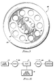
- Figure 1 is a plan view of the top side of the valve of the present invention;
- Figure 2 is a cross-sectional view of the valve along the line 2-2 in Figure 1 illustrating the configuration of the valve;
- Figure 3 is a plan view of the bottom side of the valve shown in Figures 1 and 2;
- Figure 4 is a view of the valve shown in Figures 1 to 3 installed between first and second housing portions, with the valve in the closed position;
- Figure 5 is a view of the valve of Figures 1 to 3 installed as shown in Figure 4 between the first and second housing portions, with the valve in an open position;
- Figure 6 is a schematic block diagram of the operation of a pump using two of the valves of the present invention;
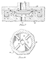
- Figure 7 is a cross-sectional view of an alternative embodiment using valve stop ribs on the floor of the lower housing portion to prevent over travel by the valve disc rather than using bumps on the bottom side of the valve disc; and
- Figure 8 is a cross-sectional view of the top side of the lower housing portion along the line 8-8 in Figure 7.
- A possible configuration for an infusion pump using two of the valves of the present invention is illustrated schematically in Figure 6. Medication contained in a fluid source 10 is to be provided to a patient via a catheter 12, which is of standard design and well known in the art. The fluid driver may be generically described as a pump 14, which may be any of a number of different arrangements, the most common of which is a variable displacement piston and cylinder arrangement.
- The pump 14 is driven by a
pump driving mechanism 16, which may also be any of a number of different arrangements which are known for controlling an infusion pump. Two one-way valves 18A, 18B are used to control the pumping force generated by the pump 14. The first one-way valve 18A is located in the fluid path between the fluid source 10 and the pump 14, and will only allow fluid to pass from the fluid source 10 to the pump 14. The second one-way valve 18B is located between the pump 14 and the catheter 12, and will only allow fluid to pass from the pump 14 to the catheter 12. - When the displacement of the pump 14 is increasing, fluid will be drawn into the pump 14. Since the second valve 18B will not allow fluid to flow into the pump 14, fluid will be drawn from the fluid source 10 through the
first valve 18A into the pump 14. Likewise, when the displacement of the pump 14 is decreasing, fluid will be forced out from the pump 14. Since thefirst valve 18A will not allow fluid to flow out from the pump 14, fluid will be forced out from the pump 14 through the second valve 18B into the catheter. - For a disposable pump, the two
valves 18A and 18B, and the pump 14 would be the disposable components (presumably together with the associated tubing, the catheter, and the empty fluid source). The present invention focuses on the construction of thevalves 18A and 18B, which are usually identical. It will be appreciated by one skilled in the art that the present invention may be adapted to have application in virtually any infusion pump conceivable. - Referring now to Figures 1 to 3, a
valve 20 is illustrated which is constructed according to the teachings of the present invention. Basically, thevalve 20 consists of three elements, the first of which is arigid valve disc 22 which includes sealing means and which functions as the actual valve element. The second element of thevalve 20 is astatic seal ring 24 which acts both as a seal between upper and lower housing elements (not shown in Figures 1 and 2) and as a rigid support structure from which thevalve disc 22 may be suspended. The third element is athin support web 26 extending between the inner diameter of thestatic seal ring 24 and the outer diameter of thevalve disc 22. The support web is used both to support thevalve disc 22 in the proper operating location within housing elements and to bias thevalve disc 22 to a closed position which a preselected force in the proper direction may be overcome to open thevalve 20. - The
valve 20 is quite small, typically having a diameter of approximately 0.20 - 0.75 inches (5.1 - 19.1mm). In the preferred embodiment shown, avalve 20 will be described herein by way of example which has a diameter of 0.33 inches (8.4mm). It will be recognised by those skilled in the art that the teachings of the present invention are equally applicable to valves of differing sizes for use in such medical devices. - The
valve disc 22 is relatively thick to prevent it from exhibiting a significant amount of flexure, particularly under situations when a high pressure in the direction opposite to normal flow would otherwise tend to cause a deflection. It will be appreciated by those skilled in the art that infusion pumps have a relatively small pump displacement, and therefore even a small amount of flexure by thevalve disc 22 during pumping would result in both a significant reduction in volumetric efficiency and in an imprecise amount of medication being delivered, making the pump unsuitable for the medical use for which is is intended. In the example used herein, thevalve disc 22 has a diameter of 0.12 inches (3.0mm) and a thickness of 0.025 inches (0.635mm) - As used throughout this disclosure, the term "top" of the
valve 20 shall be used to mean the side from which fluid originates, and the term "bottom" of thevalve 20 shall mean the side of thevalve 20 from which fluid leaves as it passes through thevalve 20. The side shown in the plan view of Figure 1 is the top side of thevalve 20, and the side shown in the plan view of Figure 3 is the bottom side of thevalve 20. The top side is shown in Figure 2 at the top of the figure when viewed in the conventional manner, and the bottom is likewise shown at the bottom of the figure. - The
valve 20 has on its bottom side four protruding circular ridges or bumps 28, as shown best in Figure 3. The fourbumps 28 are mounted around and extended from the periphery of thevalve disc 22 on the bottom side of thevalve disc 22. They are evenly distributed around the bottom of thevalve disc 22, at ninety degree intervals. The purpose of thebumps 28 is to prevent thevalve disc 22 from bottoming out and closing off the fluid path as will be discussed later in this specification. - The
valve disc 22 has on the top side of thevalve 20 from which fluid originates adynamic sealing ridge 30, shown best in Figures 1 and 2. Thedynamic sealing ridge 30 is generally cylindrical and extends upwards from the outside edge of thevalve disc 22. Thedynamic sealing ridge 30 extends 0.01 inches (2.54mm) above the surface of thevalve disc 22 in the valve shown, and has a rounded top surface for enhanced sealing characteristics. - It will of course be appreciated by those skilled in the art that the shape of the
valve disc 22 may be other than circular as shown herein. Additionally, the configurations of thebumps 28 or the sealingridge 30 may be different, the designs discussed above merely representing the preferred embodiment. - The
static seal ring 24 is located concentrically around thevalve disc 22, and functions to support and locate thevalve disc 22 in position. The static seal ring also functions as a gasket or an 0-ring to seal the space between the two housing portions, as will become more evident below in conjuction with the discussion of Figures 3 and 4. It is important to note that while the cross-sectional configuration of thestatic seal ring 24 shown in Figure 2 is the preferred embodiment, other configurations are possible. The static seal ring must present both a convenient sealing design and a structurally sound base from which thevalve disc 22 is supported. The U-shaped cross-sectionstatic seal ring 24 shown in Figure 2 accomplishes both objectives admirably. - The
thin support web 26 is used to support thevalve disc 22 from thestatic seal ring 24, with the valve disc being capable of movement in essentially one direction only ie up and down. Since theentire valve 20 is constructed of elastomeric material, it will be appreciated that theweb 26 will tend to bias thevalve disc 22 to the position shown in Figure 2 when no outside forces are applied to thevalve 20. In this position the top surface of thestatic seal ring 24 and thesupport web 26 are entirely planar, with the dynamic sealing ridge and a portion of thevalve disc 22 protruding above this plane. - By manufacturing the
valve 20 with uniform dimensions, the force, and hence the fluid pressure, required to displace thevalve disc 22 will be highly repeatable. Since the fluid pressure required to supply this force is to be very small, ie on the order of 0.1 PSI (70.3kg/m2) it will be appreciated that the support web must be very thin. - An additional factor is the use in the
valve 20 of the present invention of a plurality ofapertures 32 through the support web, theapertures 32 being arranged uniformly around the circumference of thevalve disc 22. In the preferred embodiment shown there are 10apertures 32 in thesupport web 26, eachaperture 32 having a diameter of 0.042 inches (1.07mm). Since the outer diameter of thesupport web 26 where it is connected to thestatic seal ring 24 is 0.25 inches (6.35mm) in the preferred embodiment, the apertures remove a substantial portion of thesupport web 26, thereby diminishing the force and the fluid pressure necessary to displace the valve disc. The practical effect of theapertures 32 is that thesupport web 26 may be made thicker, which in the manufacturing sense makes thevalve 20 both easier and more inexpensive to fabricate. of course, theapertures 32 also serve the purpose of allowing passage of the fluid entering thevalve 20 when thevalve disc 22 is open. - It will be appreciated that the
valve 20 may be manufactured by moulding procedures well known in the art, such as but not limited to injection moulding or transfer moulding, with thevalve 20 illustrated being manufactured as a one piece construction. The valve is typically moulded of a medical grade elastomer such as silicone rubber. A critical design criterium is the hardness of the elastomer, which is a compromise between conflicting design considerations. - The
static seal ring 24 must have a low stress relaxation characteristic in order to form a good seal after an extended shelf life. A durometer hardness of 30 to 70 on the Shore A scale encompasses the outer limit's on hardness of the material used for thevalve 20, with the hardness in the preferred embodiment being between 40 and 50 on the Shore A scale. - With the construction of the
valve 20 being accomplished in sufficient detail, the installation of avalve 20 in the two housing portions is illustrated in Figure 4. Thestatic seal ring 24 of thevalve 20 is inserted into a circularseal retaining slot 40 in alower housing portion 42. The retainingslot 40 is of sufficient depth to accept the portion of thestatic seal ring 24 in a sealing manner. - An
upper housing portion 44 is then lowered into position over thevalve 20 and thelower housing portion 44, and secured in position by any of number of techniques well known in the art, such as by snapping theupper housing portion 44 onto thelower housing portion 42. The installation of theupper housing portion 44 onto the lower housing portion will also compress thestatic seal ring 24 to form an excellent seal between theupper housing portion 44 and thelower housing portion 42 at the location of thestatic seal ring 24. - Also illustrated in Figure 4 is an optional circular
protruding ridge 45, which may be formed on the upper housing portion in a manner whereby the circular protrudingridge 45 will be located over a central portion of the top of thestatic seal ring 24 to ensure an even better seal. It should be noted that with the possible exception of the protrudingridge 45, the side of theupper housing portion 44 facing thevalve 20 is flat, thereby accomplishing one of the objects of the present invention. - Centrally located above the
valve disc 22 and within thedynamic sealing ridge 30 is aninlet aperture 46, through which fluid may be admitted to the valve. Since the side of theupper housing portion 44 facing thevalve 20 is flat, it will be appreciated that the installation of theupper housing portion 44 over thevalve 20 causes thedynamic sealing ridge 30 and thevalve disc 22 to be moved downwardly, thereby prestressing thesupport web 26 and preloading thevalve 20 in a closed position. The pressure differential must reach the threshold value in order to open thevalve 20 by forcing thevalve disc 22 and thedynamic sealing ridge 30 away from theupper housing portion 44. In the preferred embodiment described herein, the preload requires only a minimal break pressure to open the valve, typically about 0.1 PSI (70.3kg/m2). It is important that the material of thevalve 20 should have characteristics such that this prestressing of thevalve 20 does not result in stress relaxation by the material, as discussed above. - It will be noted that the design of the
valve 20 on the inlet side requires and allows only a very small volume of fluid to be stored in the cavity formed between the top of thevalve disc 22, the interior of thedynamic sealing ridge 30, and the side of theupper housing portion 44 facing thevalve 20. It is important to minimise the volume contained within this area on the inlet side of thevalve 20 when thevalve 20 is used as the valve 18B at the outlet side of the pump 14 shown in Figure 6. - The design of the
valve 20 also allows this volume to be minimised on the outlet side of thevalve 20. Referring again to Figure 4, aweb support 48 is integrally fashioned in the lower housing portion radially inside theseal retaining slot 40, with the web support forming the interior side of theseal retaining slot 40. As its name implies, the web support also extends inwardly from the seal retaining slot slightly to support a small portion of thesupport web 26, in the process slightly increasing the force required to open thevalve 20. - An additional function of the
web support 48 is to minimise the volume in the chamber outside of thedynamic sealing ridge 30 and between theupper housing portion 44 and thelower housing portion 42, this chamber being on the outlet side of thevalve 20. Thevalve chamber floor 50 is located beneath thevalve disc 22 and anoutlet aperture 52 is located in thevalve chamber floor 50. The web support may be larger than depicted in Figure 4 so long as it does not obstruct thevalve disc 22 or the flow of fluid through theapertures 32 and around thevalve discs 22. Theweb support 48 therefore minimised the volume contained on the outlet side of thevalve 20, which is important when thevalve 20 is used as thevalve 18A at the inlet side of the pump 14 shown in Figure 6. - Since the force needed to open the
valve 20 is very small, it is important to prevent a situation where a high inlet pressure could force thevalve disc 22 to thevalve chamber floor 50, thereby obstructing theoutlet aperture 52 and the flow through thevalve 20. The four protrudingcircular bumps 28, discussed above in conjuction with Figures 2 and 3, extend away from the bottom side of thevalve disc 22 to prevent thevalve disc 22 from blocking theoutlet aperture 52 even under the conditions described above. The spaces between thebumps 28 and the facing surfaces of thevalve disc 22 and thefloor 50 of thelower housing portion 42 thereby provide a fluid path even when thevalve disc 22 is forced downwards by excessive force. - Alternatively, rather than having the
bumps 28 moulded into the bottom of thevalve disc 22, apparatus for preventing thevalve disc 22 from blocking theoutlet aperture 52 under the conditions described above could be located on thefloor 50 of thelower housing portion 42. The bottom side of thevalve disc 22 would not have the protruding bumps 28 but rather would be essentially flat with a rounded bottom edge. As shown in Figures 7 and 8, one or more valve stopribs 54 which protrude from thefloor 50 of thelower support portion 42 prevent thevalve disc 22 from bottoming out and obstructing theoutlet aperture 52. The space between thevalve stop ribs 54 would thereby provide a fluid path when thevalve disc 22 is against thevalve stop ribs 54. - The spring action of the
support web 26 will maintain thedynamic sealing ridge 30 of thevalve disc 26 against theupper housing portion 44 as shown in Figure 4 when there is no fluid pressure, when the pressure differential across the valve is less than the break pressure, and when the pressure on the outlet side of thevalve 20 is greater than the pressure on the inlet side of thevalve 20. When the pressure on the inlet side of thevalve 20 is greater than the pressure on the outlet side of thevalve 20 by a value at least that of the break pressure, thevalve 20 will open as shown in Figure 5, allowing fluid to flow in theinlet aperture 46, around thedynamic sealing ridge 30, through theapertures 32 in thesupport web 26, and out theoutlet aperture 52. - The
support web 26 will act to return thevalve 20 to a closed position when the pressure across thevalve 20 drops below the break pressure. Thevalve 20 is highly resistant to reverse flow since thevalve disc 22 is relatively thick to prevent substantial deflection, thereby maintaining thedynamic sealing ridge 30 tightly against theupper housing portion 44. - It is therefore apparent that the design of the
valve 20 to have a desired break pressure is determined by three factors. First, the thicker the support web, the higher the spring rate and the greater the break pressure of thevalve 20. Secondly, theapertures 32 in the support web act to reduce the spring rate and the break pressure of the valve 200 as the number and size of the apertures increase. Finally, the height by which thedynamic sealing ridge 30 projects above thesupport web 26 provides an offset which determines the preload of the valve disc 33 and thedynamic sealing ridge 30 against theupper housing portion 44. - The
valve 20 of the present invention is highly precise, and may be economically manufactured. It is suitable for use in medical devices since it is precise, has good shelf and operating lives, and is made of medical grade materials. Thevalve 20 has a very small break pressure, yet it seals tightly when this break pressure is not met. It may be used in conjunction with a flat top surface (the upper housing portion 44), thereby making construction of a more economical infusion pump possible and making practical an inexpensive disposable pump with positive valve operation. The present invention thereby represents a valuable and highly desirable improvement in the art, while affording no relative disadvantages.
Claims (11)
Applications Claiming Priority (2)
| Application Number | Priority Date | Filing Date | Title |
|---|---|---|---|
| US06/867,824 US4712583A (en) | 1986-05-27 | 1986-05-27 | Precision passive flat-top valve for medication infusion system |
| US867824 | 1986-05-27 |
Publications (4)
| Publication Number | Publication Date |
|---|---|
| EP0247824A2 EP0247824A2 (en) | 1987-12-02 |
| EP0247824A3 EP0247824A3 (en) | 1990-11-22 |
| EP0247824B1 true EP0247824B1 (en) | 1995-05-24 |
| EP0247824B2 EP0247824B2 (en) | 1998-03-04 |
Family
ID=25350527
Family Applications (1)
| Application Number | Title | Priority Date | Filing Date |
|---|---|---|---|
| EP19870304641 Expired - Lifetime EP0247824B2 (en) | 1986-05-27 | 1987-05-26 | Valve for medication infusion system |
Country Status (3)
| Country | Link |
|---|---|
| US (1) | US4712583A (en) |
| EP (1) | EP0247824B2 (en) |
| DE (1) | DE3751314T3 (en) |
Cited By (1)
| Publication number | Priority date | Publication date | Assignee | Title |
|---|---|---|---|---|
| US7316662B2 (en) | 2002-07-09 | 2008-01-08 | Gambro Lundia Ab | Infusion device for medical use |
Families Citing this family (132)
| Publication number | Priority date | Publication date | Assignee | Title |
|---|---|---|---|---|
| DE8432064U1 (en) * | 1984-11-02 | 1985-05-02 | Codan Medizinische Geräte GmbH & Co KG, 2432 Lensahn | DEVICE FOR REGULATING FLOW IN GRAVITY INFUSION AND TRANSFUSION |
| FR2618874B1 (en) * | 1987-07-28 | 1989-12-08 | Abx Sa | AUTOMATIC MEMBRANE BLEEDING DEVICE FOR PNEUMATIC CIRCUITS |
| NL8800020A (en) * | 1988-01-06 | 1989-08-01 | Henk Schram | INFLATABLE BODY WITH A VALVE, AND PACKAGING WITH SUCH A BODY. |
| US4915351A (en) * | 1989-06-30 | 1990-04-10 | Hoffman Albert R | Hose coupling valve |
| US5093047A (en) * | 1990-01-18 | 1992-03-03 | Roediger Pittsburgh, Inc. | Gas diffuser |
| US4986310A (en) * | 1990-01-22 | 1991-01-22 | Vernay Laboratories, Inc. | Low pressure check valve |
| US5103854A (en) * | 1990-01-22 | 1992-04-14 | Vernay Laboratories, Inc. | Low pressure check valve for artificial respiration devices |
| US5025829A (en) * | 1990-01-29 | 1991-06-25 | Harmac Medical Products, Inc. | Parenteral check valve |
| US5554117A (en) * | 1990-03-01 | 1996-09-10 | Michigan Transtech Corporation | Implantable access devices |
| US5053013A (en) * | 1990-03-01 | 1991-10-01 | The Regents Of The University Of Michigan | Implantable infusion device |
| US5350360A (en) * | 1990-03-01 | 1994-09-27 | Michigan Transtech Corporation | Implantable access devices |
| US5281199A (en) * | 1990-03-01 | 1994-01-25 | Michigan Transtech Corporation | Implantable access devices |
| US5226879A (en) * | 1990-03-01 | 1993-07-13 | William D. Ensminger | Implantable access device |
| US5263930A (en) * | 1990-03-01 | 1993-11-23 | William D. Ensminger | Implantable access devices |
| US5356381A (en) * | 1990-03-01 | 1994-10-18 | Ensminger William D | Implantable access devices |
| US5180365A (en) * | 1990-03-01 | 1993-01-19 | Ensminger William D | Implantable infusion device |
| US5057084A (en) * | 1990-03-01 | 1991-10-15 | The Regents Of The University Of Michigan | Implantable infusion device |
| US5352204A (en) * | 1990-03-01 | 1994-10-04 | Ensminger William D | Implantable access devices |
| US5176176A (en) * | 1991-11-14 | 1993-01-05 | Graco Inc. | Non-degrading back pressure regulator |
| US5226886A (en) * | 1991-12-06 | 1993-07-13 | Baxter International, Inc. | Ambulatory tubing set with anti-siphon valve |
| US5215538A (en) * | 1992-02-05 | 1993-06-01 | Abbott Laboratories | Connector-activated in-line valve |
| US5348179A (en) * | 1992-05-11 | 1994-09-20 | Walker Stainless Equipment Company, Inc. | Venting cap assembly |
| DE4304949C2 (en) * | 1993-02-18 | 1996-07-18 | Filtertek Sa | Check valve for medical applications in fluid technology |
| US5408704A (en) * | 1993-09-09 | 1995-04-25 | Sealand Technology, Inc. | Low volume vacuum toilet assembly |
| WO1995009987A1 (en) * | 1993-10-04 | 1995-04-13 | Research International, Inc. | Micromachined fluid flow regulators |
| FR2721216A1 (en) * | 1994-06-21 | 1995-12-22 | Bruno Chene | Drainage implant for treating hydrocephalus |
| GB2295095B (en) * | 1994-11-19 | 1998-07-15 | Smiths Industries Plc | Humidifier system with valved water supply |
| DE4446170A1 (en) * | 1994-12-23 | 1996-06-27 | Bosch Gmbh Robert | Pump locking valve arrangement for IC engine fuel evaporation prevention system |
| US5727594A (en) * | 1995-02-09 | 1998-03-17 | Choksi; Pradip | Low actuation pressure unidirectional flow valve |
| WO1997002059A1 (en) * | 1995-07-06 | 1997-01-23 | Disetronic Licensing Ag | Disposable cassette for connection to a liquid drug infusion pump |
| GB2308424B (en) * | 1995-12-19 | 1999-09-29 | Mangar International Ltd | Pressure control valve |
| US5728078A (en) * | 1996-03-19 | 1998-03-17 | Powers Dental & Medical Technologies Inc. | Medical suctioning bacteria valve and related method |
| US6883778B1 (en) | 1996-11-18 | 2005-04-26 | Nypro Inc. | Apparatus for reducing fluid drawback through a medical valve |
| KR100457361B1 (en) * | 1996-11-18 | 2004-11-16 | 나이프로 인크. | Swabbable luer-coned valve |
| US7789864B2 (en) | 1996-11-18 | 2010-09-07 | Nypro Inc. | Luer-activated valve |
| US6290682B1 (en) | 1997-02-13 | 2001-09-18 | Filterek Inc. | Infusion set |
| US5848605A (en) * | 1997-11-12 | 1998-12-15 | Cybor Corporation | Check valve |
| US6162206A (en) * | 1997-12-23 | 2000-12-19 | Baxter International Inc. | Resealable access site |
| IL123227A0 (en) | 1998-02-08 | 1998-09-24 | 3By Ltd | Check valve |
| US6021961A (en) * | 1998-03-06 | 2000-02-08 | Flexible Products Company | Crossover-resistant plural component mixing nozzle |
| US5992462A (en) * | 1998-10-28 | 1999-11-30 | Vernay Laboratories, Inc. | Disc type check valve |
| US6027097A (en) * | 1998-12-03 | 2000-02-22 | Lakeshore Automatic Products, Inc. | Water stop hose connector |
| IT1311348B1 (en) * | 1999-11-12 | 2002-03-12 | Borla Ind | CHECK VALVE FOR MEDICAL INFUSION LINES AND SIMILAR. |
| IT1311347B1 (en) * | 1999-11-12 | 2002-03-12 | Borla Ind | CHECK VALVE FOR MEDICAL INFUSION LINES AND SIMILAR. |
| US6540262B1 (en) | 2000-01-10 | 2003-04-01 | James W. Humphreys | Ferrule-free hose fittings |
| US6334761B1 (en) * | 2000-03-02 | 2002-01-01 | California Institute Of Technology | Check-valved silicon diaphragm pump and method of fabricating the same |
| WO2002004046A2 (en) * | 2000-07-07 | 2002-01-17 | Fluidsense Corporation | Infusion pump cassette |
| US6539987B1 (en) | 2000-08-10 | 2003-04-01 | Louis Dischler | Method of pressure processing enclosures having bi-stable valves |
| US6345649B1 (en) * | 2000-08-10 | 2002-02-12 | Louis Dischler | Bi-stable valve especially useful for pressurizing pen refills |
| AU2002220268A1 (en) | 2000-10-23 | 2002-05-06 | Nypro Inc. | Anti-drawback medical valve |
| JP2005500142A (en) | 2001-08-22 | 2005-01-06 | ナイプロ・インク | Medical valve with expansion member |
| GB0123054D0 (en) * | 2001-09-25 | 2001-11-14 | Randox Lab Ltd | Passive microvalve |
| US6892998B2 (en) * | 2001-10-09 | 2005-05-17 | Nypro, Inc. | Medical valve and method of assembling the same |
| US20070161970A1 (en) * | 2004-04-16 | 2007-07-12 | Medrad, Inc. | Fluid Delivery System, Fluid Path Set, and Pressure Isolation Mechanism with Hemodynamic Pressure Dampening Correction |
| US20080154214A1 (en) | 2006-12-22 | 2008-06-26 | Medrad, Inc. | Flow Based Pressure Isolation and Fluid Delivery System Including Flow Based Pressure Isolation |
| US6869426B2 (en) | 2001-11-13 | 2005-03-22 | Nypro Inc. | Anti-drawback medical valve |
| US7753892B2 (en) | 2001-11-13 | 2010-07-13 | Nypro Inc. | Anti-drawback medical valve |
| US7837658B2 (en) | 2001-11-13 | 2010-11-23 | Nypro Inc. | Anti-drawback medical valve |
| JP2003211028A (en) * | 2001-11-14 | 2003-07-29 | Asmo Co Ltd | Washer nozzle with check valve and hose joint with check valve |
| JP3780224B2 (en) * | 2002-04-30 | 2006-05-31 | Smc株式会社 | Check valve device |
| DE10219994B4 (en) * | 2002-05-03 | 2005-09-29 | Filtertek B.V. | One-way valve means |
| JP2004083013A (en) * | 2002-06-26 | 2004-03-18 | Katsutoshi Masuda | Valve mechanism |
| US6886929B2 (en) * | 2002-10-25 | 2005-05-03 | Hewlett-Packard Development Company, L.P. | Techniques for improving pressure sensor shock robustness in fluid containment devices |
| US7465040B2 (en) * | 2002-10-25 | 2008-12-16 | Hewlett-Packard Development Company, L.P. | Labyrinth seal structure with redundant fluid flow paths |
| US7357792B2 (en) | 2002-10-29 | 2008-04-15 | Nypro Inc. | Positive push medical valve with internal seal |
| US7287545B2 (en) * | 2003-06-10 | 2007-10-30 | Larry Saul Zelson | Sanitary check valve |
| WO2005010363A2 (en) * | 2003-07-23 | 2005-02-03 | Hargraves Technology Corporation | Pump valve with controlled stroke |
| US7914502B2 (en) | 2003-07-31 | 2011-03-29 | Nypro Inc. | Anti-drawback medical valve |
| JP2007537399A (en) * | 2004-05-11 | 2007-12-20 | オキュペイショナル・アンド・メディカル・イノベイションズ・リミテッド | One-way valve that uses fluid pressure for opening and closing |
| DE102004027734A1 (en) | 2004-06-07 | 2005-12-22 | Filtertek B.V., Newcastle West | Device for connecting a ventilator with the patient |
| US7673653B2 (en) * | 2004-06-17 | 2010-03-09 | Filtertek Inc. | Check valve |
| US7971804B2 (en) * | 2004-10-26 | 2011-07-05 | Roberts James C | Channeled shaft check valve assemblies |
| DE202005010459U1 (en) | 2004-11-22 | 2005-10-13 | Filtertek B.V., Newcastle West | Device for introducing air into containers used in artificial nutrition |
| US7887519B2 (en) | 2005-01-14 | 2011-02-15 | Nypro Inc. | Valve with internal lifter |
| EP1748235A1 (en) * | 2005-07-27 | 2007-01-31 | Pres-Block S.P.A. | Improved valve assembly |
| EP1996848A4 (en) * | 2006-03-02 | 2012-10-17 | Global Valve Technology Ltd | Dual seal valve |
| US8925579B2 (en) | 2006-03-02 | 2015-01-06 | Pacific Bag, Inc. | Pressure relief valve |
| US8968261B2 (en) | 2006-04-11 | 2015-03-03 | Np Medical Inc. | Medical valve with resilient biasing member |
| CA2660838A1 (en) | 2006-08-11 | 2008-02-21 | Nypro Inc. | Medical valve with expandable member |
| DE102006050161A1 (en) * | 2006-10-25 | 2008-04-30 | Robert Bosch Gmbh | Fuel tank reservoir for vehicle, has opening in base for filling reservoir, and bearing mounted in edge area of opening by using bar that is designed in linear shape such that flexible expansion compensation is achieved |
| EP2407191B1 (en) | 2006-10-30 | 2012-12-12 | Gambro Lundia AB | Air separator extracorporeal fluid treatment sets |
| US7540301B2 (en) * | 2006-12-27 | 2009-06-02 | Walter Tuymer | Compressor valve |
| US20080172006A1 (en) * | 2007-01-15 | 2008-07-17 | Medrad, Inc. | Patency Check Compatible Check Valve And Fluid Delivery System Including The Patency Check Compatible Check Valve |
| DE202007011811U1 (en) * | 2007-08-23 | 2007-11-08 | Filtertek B.V., Newcastle West | Check valve, in particular for medical applications |
| US8728020B2 (en) | 2007-10-04 | 2014-05-20 | Gambro Lundia Ab | Infusion apparatus |
| US7721763B2 (en) * | 2008-01-08 | 2010-05-25 | Pradip Choksi | Adjustable pressure relief valve |
| US7883198B2 (en) * | 2008-05-01 | 2011-02-08 | Xerox Corporation | Rapid response one-way valve for high speed solid ink delivery |
| CN103695530B (en) | 2008-07-07 | 2016-05-25 | 牛津纳米孔技术有限公司 | Enzyme-hole construct |
| US8627852B2 (en) * | 2009-01-22 | 2014-01-14 | Aptargroup, Inc. | Apertured flow control element and housing structure therefor |
| US8663538B2 (en) | 2009-02-12 | 2014-03-04 | Picolife Technologies, Llc | Method of making a membrane for use with a flow control system for a micropump |
| US8372046B2 (en) * | 2009-02-20 | 2013-02-12 | University Of Southern California | Drug delivery device with in-plane bandpass regulation check valve in heat-shrink packaging |
| US9222819B2 (en) | 2009-02-20 | 2015-12-29 | University Of Southern California | Tracking and controlling fluid delivery from chamber |
| US8579885B2 (en) * | 2009-02-20 | 2013-11-12 | University Of Southern California | MEMS electrochemical bellows actuator |
| JP5493961B2 (en) * | 2009-02-24 | 2014-05-14 | 株式会社村田製作所 | Check valve, fluid device and pump |
| EP3421063B1 (en) * | 2009-04-23 | 2021-03-17 | Fresenius Medical Care Deutschland GmbH | External functional device and treatment device |
| ES2696987T3 (en) | 2009-06-22 | 2019-01-21 | Np Medical Inc | Medical valve with improved backpressure seal |
| EP2448628B1 (en) * | 2009-06-29 | 2018-09-19 | Cook Medical Technologies LLC | Haemostatic valve device |
| US9138572B2 (en) | 2010-06-24 | 2015-09-22 | Np Medical Inc. | Medical valve with fluid volume alteration |
| JP5565464B2 (en) * | 2010-08-20 | 2014-08-06 | 株式会社村田製作所 | Stop valve, fuel cell system |
| US9593370B2 (en) | 2010-10-01 | 2017-03-14 | Oxford Nanopore Technologies Ltd. | Biochemical analysis apparatus and rotary valve |
| WO2012061869A1 (en) * | 2010-11-11 | 2012-05-18 | Chimden Medical Pty. Ltd. | A valve to prevent air entering an intravenous circuit |
| EP2704767A1 (en) * | 2011-05-06 | 2014-03-12 | Sanofi-Aventis Deutschland GmbH | Flexible valve geometry for the use of rigid materials |
| GB2492955A (en) | 2011-07-13 | 2013-01-23 | Oxford Nanopore Tech Ltd | One way valve |
| CN102910357B (en) * | 2011-08-02 | 2016-06-01 | 萧兆维 | Check valve and liquid container |
| CN103748361B (en) * | 2011-08-24 | 2016-03-09 | 松下电器产业株式会社 | Control valve unit and the hermetic type compressor possessing this control valve unit of compressor |
| CN103930144A (en) | 2011-09-15 | 2014-07-16 | 牛津纳米孔技术有限公司 | Piston seal |
| US8771229B2 (en) | 2011-12-01 | 2014-07-08 | Picolife Technologies, Llc | Cartridge system for delivery of medicament |
| US8790307B2 (en) | 2011-12-01 | 2014-07-29 | Picolife Technologies, Llc | Drug delivery device and methods therefor |
| US20130146166A1 (en) * | 2011-12-07 | 2013-06-13 | Serge Campeau | Auto shutoff device |
| US10130759B2 (en) | 2012-03-09 | 2018-11-20 | Picolife Technologies, Llc | Multi-ported drug delivery device having multi-reservoir cartridge system |
| US9883834B2 (en) | 2012-04-16 | 2018-02-06 | Farid Amirouche | Medication delivery device with multi-reservoir cartridge system and related methods of use |
| JP5881530B2 (en) * | 2012-05-22 | 2016-03-09 | 日立オートモティブシステムズ株式会社 | Pump device |
| US10245420B2 (en) | 2012-06-26 | 2019-04-02 | PicoLife Technologies | Medicament distribution systems and related methods of use |
| CA2886292A1 (en) * | 2012-09-28 | 2014-04-03 | Kimree Hi-Tech Inc. | Electronic cigarette and electronic cigarette device thereof |
| GB2510093A (en) | 2012-10-04 | 2014-07-30 | Owen Mumford Ltd | Pen injector with a mechanism for expelling therapeutic material by negative pressure |
| US9144672B2 (en) | 2013-03-13 | 2015-09-29 | Carefusion 303, Inc. | Needleless connector with compressible valve |
| US9089682B2 (en) * | 2013-03-14 | 2015-07-28 | Carefusion 303, Inc. | Needleless connector with support member |
| CA2809504C (en) * | 2013-03-15 | 2014-07-22 | Westport Power Inc. | Check valve with improved response time |
| JP6316294B2 (en) * | 2013-07-31 | 2018-04-25 | テルモ株式会社 | Connector and infusion set |
| WO2015024081A1 (en) * | 2013-10-18 | 2015-02-26 | Zammi Instrumental Ltda | Flow-control valve arrangements and improvements |
| DE102014210231A1 (en) | 2014-05-28 | 2015-12-03 | Robert Bosch Gmbh | Pressure compensation element with a membrane, housing, battery cell module and motor vehicle |
| GB2531991B (en) * | 2014-09-10 | 2020-07-22 | Mayborn Uk Ltd | Valve Assembly |
| US9423063B2 (en) * | 2014-11-07 | 2016-08-23 | Plum Industrial Co., Ltd | Oil pipe female coupler |
| EP3021018A1 (en) * | 2014-11-11 | 2016-05-18 | Kao Germany GmbH | Valve, container for receiving and/or mixing fluids, use of a container and method for receiving and/or mixing fluids |
| KR102367255B1 (en) * | 2015-03-25 | 2022-02-23 | 가부시끼가이샤 타쿠미나 | Non-return valve and valve body |
| EP3342449A1 (en) * | 2017-01-02 | 2018-07-04 | Fresenius Kabi Deutschland GmbH | Port device for injecting a medical fluid into a medical line |
| US11607489B2 (en) | 2017-05-26 | 2023-03-21 | Bayer Healthcare Llc | Injector state logic with hemodynamic monitoring |
| EP3652471B1 (en) * | 2017-07-11 | 2021-06-09 | Microfab Service GmbH | Micro check valve and system with multiple micro check valves and method for the production thereof |
| DE102017121334A1 (en) * | 2017-09-14 | 2019-03-14 | Danfoss Power Solution GmbH & Co OHG | Control disc with increased rigidity and method for producing such a control disc |
| US11441702B1 (en) * | 2019-05-09 | 2022-09-13 | Facebook Technologies, Llc | Fluidic valve |
| WO2021016450A1 (en) | 2019-07-24 | 2021-01-28 | Quest Medical, Inc. | Filtered vacuum relief vent valve |
| US11187333B1 (en) * | 2020-09-29 | 2021-11-30 | Carefusion 303, Inc. | Color changing and pressure sensing check valves |
Family Cites Families (10)
| Publication number | Priority date | Publication date | Assignee | Title |
|---|---|---|---|---|
| US2462189A (en) * | 1944-05-25 | 1949-02-22 | Trico Products Corp | Valve for windshield cleaners |
| US2497906A (en) * | 1944-10-20 | 1950-02-21 | Peters & Russell Inc | Valved hose connection |
| US2467189A (en) * | 1947-03-03 | 1949-04-12 | Cohen Milton | Float operated switch |
| US2758609A (en) * | 1953-05-06 | 1956-08-14 | Henry Flow Control Company | Check valve |
| US3190496A (en) * | 1963-10-14 | 1965-06-22 | Western Metal Specialty Divisi | Valve means for pressurized gas fuel |
| US4143853A (en) * | 1977-07-14 | 1979-03-13 | Metatech Corporation | Valve for use with a catheter or the like |
| US4405316A (en) * | 1978-04-03 | 1983-09-20 | Baxter Travenol Laboratories, Inc. | Injection site with check valve inlet |
| EP0031988A1 (en) * | 1980-01-04 | 1981-07-15 | Bruce De Lorenzo | Valve mechanism |
| US4355639A (en) * | 1980-05-21 | 1982-10-26 | Sis-Ter S.P.A. | Apparatus for the parenteral administration of liquids at a constant, adjustable flow rate |
| US4493339A (en) * | 1982-05-05 | 1985-01-15 | Porter Instrument Company, Inc. | Air valve for a breathing system |
-
1986
- 1986-05-27 US US06/867,824 patent/US4712583A/en not_active Expired - Lifetime
-
1987
- 1987-05-26 EP EP19870304641 patent/EP0247824B2/en not_active Expired - Lifetime
- 1987-05-26 DE DE19873751314 patent/DE3751314T3/en not_active Expired - Lifetime
Cited By (1)
| Publication number | Priority date | Publication date | Assignee | Title |
|---|---|---|---|---|
| US7316662B2 (en) | 2002-07-09 | 2008-01-08 | Gambro Lundia Ab | Infusion device for medical use |
Also Published As
| Publication number | Publication date |
|---|---|
| EP0247824A2 (en) | 1987-12-02 |
| DE3751314D1 (en) | 1995-06-29 |
| EP0247824B2 (en) | 1998-03-04 |
| EP0247824A3 (en) | 1990-11-22 |
| DE3751314T3 (en) | 1998-08-20 |
| DE3751314T2 (en) | 1996-04-11 |
| US4712583A (en) | 1987-12-15 |
Similar Documents
| Publication | Publication Date | Title |
|---|---|---|
| EP0247824B1 (en) | Valve for medication infusion system | |
| US6089272A (en) | Check valve | |
| US5025829A (en) | Parenteral check valve | |
| US5431634A (en) | Ambulatory pump | |
| EP0288716B1 (en) | Cassette for an infusion system | |
| CA1152823A (en) | Implantable drug infusion regulator | |
| US4898584A (en) | Implantable patient-activated fluid delivery device | |
| US4946448A (en) | Check valve for use with intravenous pump | |
| US4141379A (en) | Check valve | |
| US4381005A (en) | Intravenous pump chamber | |
| US4898585A (en) | Implantable patient-activated fluid delivery device with bolus injection port | |
| US5433710A (en) | Medication infusion pump with fluoropolymer valve seat | |
| US5988211A (en) | I.V. flow controller | |
| US4354492A (en) | Medical administration set with backflow check valve | |
| US5305795A (en) | Nonreturn valve, in particular for medical infusion appliances | |
| US4548607A (en) | Implantable manually actuated medication dispensing system | |
| EP1476209B1 (en) | Device for administering of medication in fluid form | |
| US4152098A (en) | Micropump | |
| CA1176933A (en) | Diaphragm type blood pump for medical use | |
| US7819838B2 (en) | Cassette for use in a medication delivery flow sensor assembly and method of making the same | |
| RU2645362C2 (en) | One way valve | |
| US20020004015A1 (en) | Cassette | |
| JPS59111765A (en) | Injection pump apparatus | |
| US4827973A (en) | One way flow valve | |
| GB2037949A (en) | Valve |
Legal Events
| Date | Code | Title | Description |
|---|---|---|---|
| PUAI | Public reference made under article 153(3) epc to a published international application that has entered the european phase |
Free format text: ORIGINAL CODE: 0009012 |
|
| AK | Designated contracting states |
Kind code of ref document: A2 Designated state(s): DE FR GB IT NL SE |
|
| PUAL | Search report despatched |
Free format text: ORIGINAL CODE: 0009013 |
|
| AK | Designated contracting states |
Kind code of ref document: A3 Designated state(s): DE FR GB IT NL SE |
|
| 17P | Request for examination filed |
Effective date: 19910502 |
|
| 17Q | First examination report despatched |
Effective date: 19921127 |
|
| RAP1 | Party data changed (applicant data changed or rights of an application transferred) |
Owner name: IVAC CORPORATION |
|
| GRAA | (expected) grant |
Free format text: ORIGINAL CODE: 0009210 |
|
| AK | Designated contracting states |
Kind code of ref document: B1 Designated state(s): DE FR GB IT NL SE |
|
| ITF | It: translation for a ep patent filed |
Owner name: BARZANO' E ZANARDO ROMA S.P.A. |
|
| REF | Corresponds to: |
Ref document number: 3751314 Country of ref document: DE Date of ref document: 19950629 |
|
| ET | Fr: translation filed | ||
| PLBQ | Unpublished change to opponent data |
Free format text: ORIGINAL CODE: EPIDOS OPPO |
|
| PLBI | Opposition filed |
Free format text: ORIGINAL CODE: 0009260 |
|
| PLBF | Reply of patent proprietor to notice(s) of opposition |
Free format text: ORIGINAL CODE: EPIDOS OBSO |
|
| 26 | Opposition filed |
Opponent name: DISETRONIC MEDICAL SYSTEMS AG Effective date: 19960214 |
|
| NLR1 | Nl: opposition has been filed with the epo |
Opponent name: DISETRONIC MEDICAL SYSTEMS AG |
|
| RAP2 | Party data changed (patent owner data changed or rights of a patent transferred) |
Owner name: IVAC MEDICAL SYSTEMS, INC. |
|
| PLBF | Reply of patent proprietor to notice(s) of opposition |
Free format text: ORIGINAL CODE: EPIDOS OBSO |
|
| PLBF | Reply of patent proprietor to notice(s) of opposition |
Free format text: ORIGINAL CODE: EPIDOS OBSO |
|
| RAP2 | Party data changed (patent owner data changed or rights of a patent transferred) |
Owner name: IVAC MEDICAL SYSTEMS, INC. |
|
| NLT2 | Nl: modifications (of names), taken from the european patent patent bulletin |
Owner name: IVAC MEDICAL SYSTEMS, INC. |
|
| NLT2 | Nl: modifications (of names), taken from the european patent patent bulletin |
Owner name: IVAC MEDICAL SYSTEMS, INC. |
|
| NLT1 | Nl: modifications of names registered in virtue of documents presented to the patent office pursuant to art. 16 a, paragraph 1 |
Owner name: IVAC MEDICAL SYSTEMS, INC. |
|
| REG | Reference to a national code |
Ref country code: FR Ref legal event code: CD Ref country code: FR Ref legal event code: CA |
|
| PLAW | Interlocutory decision in opposition |
Free format text: ORIGINAL CODE: EPIDOS IDOP |
|
| PLAW | Interlocutory decision in opposition |
Free format text: ORIGINAL CODE: EPIDOS IDOP |
|
| PUAH | Patent maintained in amended form |
Free format text: ORIGINAL CODE: 0009272 |
|
| STAA | Information on the status of an ep patent application or granted ep patent |
Free format text: STATUS: PATENT MAINTAINED AS AMENDED |
|
| 27A | Patent maintained in amended form |
Effective date: 19980304 |
|
| AK | Designated contracting states |
Kind code of ref document: B2 Designated state(s): DE FR GB IT NL SE |
|
| ITF | It: translation for a ep patent filed |
Owner name: BARZANO' E ZANARDO ROMA S.P.A. |
|
| NLR2 | Nl: decision of opposition | ||
| ET3 | Fr: translation filed ** decision concerning opposition | ||
| NLR3 | Nl: receipt of modified translations in the netherlands language after an opposition procedure | ||
| NLS | Nl: assignments of ep-patents |
Owner name: IVAC HOLDING, INC. |
|
| NLT1 | Nl: modifications of names registered in virtue of documents presented to the patent office pursuant to art. 16 a, paragraph 1 |
Owner name: ALARIS MEDICAL SYSTEMS, INC. |
|
| REG | Reference to a national code |
Ref country code: FR Ref legal event code: TP Ref country code: FR Ref legal event code: CD |
|
| REG | Reference to a national code |
Ref country code: GB Ref legal event code: IF02 |
|
| REG | Reference to a national code |
Ref country code: GB Ref legal event code: 732E |
|
| REG | Reference to a national code |
Ref country code: FR Ref legal event code: CD |
|
| PGFP | Annual fee paid to national office [announced via postgrant information from national office to epo] |
Ref country code: FR Payment date: 20060517 Year of fee payment: 20 |
|
| PGFP | Annual fee paid to national office [announced via postgrant information from national office to epo] |
Ref country code: NL Payment date: 20060524 Year of fee payment: 20 |
|
| PGFP | Annual fee paid to national office [announced via postgrant information from national office to epo] |
Ref country code: GB Payment date: 20060525 Year of fee payment: 20 |
|
| PGFP | Annual fee paid to national office [announced via postgrant information from national office to epo] |
Ref country code: SE Payment date: 20060530 Year of fee payment: 20 |
|
| PGFP | Annual fee paid to national office [announced via postgrant information from national office to epo] |
Ref country code: IT Payment date: 20060531 Year of fee payment: 20 |
|
| REG | Reference to a national code |
Ref country code: GB Ref legal event code: 732E |
|
| PGFP | Annual fee paid to national office [announced via postgrant information from national office to epo] |
Ref country code: DE Payment date: 20060630 Year of fee payment: 20 |
|
| NLS | Nl: assignments of ep-patents |
Owner name: CARDINAL HEALTH 303, INC. Effective date: 20060405 |
|
| PG25 | Lapsed in a contracting state [announced via postgrant information from national office to epo] |
Ref country code: NL Free format text: LAPSE BECAUSE OF EXPIRATION OF PROTECTION Effective date: 20070526 |
|
| REG | Reference to a national code |
Ref country code: GB Ref legal event code: PE20 |
|
| EUG | Se: european patent has lapsed | ||
| NLV7 | Nl: ceased due to reaching the maximum lifetime of a patent |
Effective date: 20070526 |
|
| PG25 | Lapsed in a contracting state [announced via postgrant information from national office to epo] |
Ref country code: GB Free format text: LAPSE BECAUSE OF EXPIRATION OF PROTECTION Effective date: 20070525 |