EP0255407A2 - Method and apparatus for removing pseudo-sync and/or automatic gain control pulses from a video signal - Google Patents
Method and apparatus for removing pseudo-sync and/or automatic gain control pulses from a video signal Download PDFInfo
- Publication number
- EP0255407A2 EP0255407A2 EP87308207A EP87308207A EP0255407A2 EP 0255407 A2 EP0255407 A2 EP 0255407A2 EP 87308207 A EP87308207 A EP 87308207A EP 87308207 A EP87308207 A EP 87308207A EP 0255407 A2 EP0255407 A2 EP 0255407A2
- Authority
- EP
- European Patent Office
- Prior art keywords
- video signal
- pulses
- sync
- sync pulses
- pseudo
- Prior art date
- Legal status (The legal status is an assumption and is not a legal conclusion. Google has not performed a legal analysis and makes no representation as to the accuracy of the status listed.)
- Granted
Links
Images

Classifications
-
- H—ELECTRICITY
- H04—ELECTRIC COMMUNICATION TECHNIQUE
- H04N—PICTORIAL COMMUNICATION, e.g. TELEVISION
- H04N5/00—Details of television systems
- H04N5/76—Television signal recording
- H04N5/91—Television signal processing therefor
- H04N5/913—Television signal processing therefor for scrambling ; for copy protection
-
- H—ELECTRICITY
- H04—ELECTRIC COMMUNICATION TECHNIQUE
- H04N—PICTORIAL COMMUNICATION, e.g. TELEVISION
- H04N7/00—Television systems
- H04N7/16—Analogue secrecy systems; Analogue subscription systems
- H04N7/167—Systems rendering the television signal unintelligible and subsequently intelligible
- H04N7/169—Systems operating in the time domain of the television signal
-
- H—ELECTRICITY
- H04—ELECTRIC COMMUNICATION TECHNIQUE
- H04N—PICTORIAL COMMUNICATION, e.g. TELEVISION
- H04N7/00—Television systems
- H04N7/16—Analogue secrecy systems; Analogue subscription systems
- H04N7/167—Systems rendering the television signal unintelligible and subsequently intelligible
- H04N7/171—Systems operating in the amplitude domain of the television signal
-
- H—ELECTRICITY
- H04—ELECTRIC COMMUNICATION TECHNIQUE
- H04N—PICTORIAL COMMUNICATION, e.g. TELEVISION
- H04N5/00—Details of television systems
- H04N5/76—Television signal recording
- H04N5/91—Television signal processing therefor
- H04N5/913—Television signal processing therefor for scrambling ; for copy protection
- H04N2005/91307—Television signal processing therefor for scrambling ; for copy protection by adding a copy protection signal to the video signal
- H04N2005/91314—Television signal processing therefor for scrambling ; for copy protection by adding a copy protection signal to the video signal the copy protection signal being a pulse signal inserted in blanking intervals of the video signal, e.g. pseudo-AGC pulses, pseudo-sync pulses
Definitions
- the present invention pertains to a method and apparatus for removing added pulses from a video signal to render copiable the video signal. More particularly, the present invention pertains to such a method and process for removing pseudo-sync pulses which have been added to a video signal, or AGC (positive) pulses added to a video signal for the purpose of inhibiting copying of the video signal.
- the present method and apparatus are also useful with various combinations of the added pulses stated above.
- Applicant's United States Patent 4,631,603 issued December 23, 1986 entitled METHOD AND APPARATUS FOR PROCESSING A VIDEO SIGNAL SO AS TO INHIBIT THE MAKING OF ACCEPTABLE VIDEO TAPE RECORDINGS discloses how a video signal can be modified so that a television set produces normal video pictures from the modified signal, but a videotape recording made from the modified signal produces generally unacceptable pictures.
- the foregoing "inhibit" invention relies on the addition .of high level positive pulses (hereinafter referred to as AGC pulses) to the video signal, following the trailing edges of some percentage of the sync pulses.
- AGC pulses high level positive pulses
- This pulse addition occurs during the back porch region of the video signal, i.e., within the blanking interval.
- These added pulses cause the video signal level automatic gain control system in a videotape recorder to make an erroneous assessment of video signal level, thereby leading to an unacceptable or bad recording of the video signal.
- the sync pulses referred to can be either the normal sync pulses of the video signal (including both equalizing and broad pulses) or the pseudo-sync pulses added to the video signal.
- the pseudo-sync signals which extend from the blanking signal level of the video signal to the normal sync tip level, are added to the video signal during some of the lines of the vertical blanking interval.
- blanking interval lines may be added immediately preceding and/or following this normal vertical blanking interval. These added lines would then be especially blanked for the "inhibit" feature purpose.
- each of the pseudo-sync pulses will be followed respectively by an AGC pulse (i.e., positive pulse), whereas only a fraction of the normal sync pulses in a video signal would be expected to be followed by an AGC pulse.
- AGC pulse i.e., positive pulse
- This invention concerns a method and apparatus for removing from a video signal pseudo-sync and/or AGC pulses which have been added to inhibit recording of the video signal, in any format .
- the added pulses may be present in a given modified video signal.
- Such removal thereby allows the video signal to be recorded normally.
- one object of this invention is to provide a method and apparatus for removing pseudo-sync and AGC pulses from a modified video signal so that a videotape recording may be normally made of the "cleaned-up" video signal.
- the present invention enables normal video recordings to be made of any modified video signals which have pseudo-sync pulses and/or AGC pulses added for the purpose of inhibiting recording of the modified video signal.
- added AGC pulses are removed from the video signal by selective blanking of the video signal during predetermined time periods following the occurrence of sync pulses.
- removal of added pseudo-sync pulses is accomplished by selective clipping of the negative-going pseudo-sync pulses based on sensing of the sync pulses, along with generation of a line frequency square wave.
- the present invention encompasses both method and apparatus for achieving removal of any one of the foregoing types of pulses added for defeating recording, or any combination of such "inhibit" pulses.
- the buffer amplifier 10 may be a unity-gain amplifier which passes the video signal with its added pulses to a sync tip clamp 12.
- Clamp 12 causes the negative voltage sync tips of both the normally-occurring sync pulses and the added pseudo-sync pulses to be held at a constant negative voltage despite any variation in the average picture signal level, the amplifier gain levels, or other sources of bias.
- the clamping voltage of the sync tip claim 12 is chosen so that the blanking-level voltage of the video signal at this point is 0 volts, or very close thereto. This fact requires that the overall video signal level be fixed and known.
- FIG. 1 merely utilizes a sync tip clamp, as is known to one of ordinary skill in the art.
- Other elemental devices which are readily recognized and understood by one of ordinary skill in the art, such as the sync separator and the monostable multivibrators, are shown diagramatically only.
- FIGURE 2a illustrates a video signal modified as discussed to inhibit its being recorded, and as output by the sync tip clamp 12.
- Reference character 16 shows a normal sync pulse
- reference characters 18 illustrate pseudo-sync pulses in accordance with the "inhibiting" modifications made to a video signal.
- Reference characters 20 of FIGURES 2a, g, h and i show color burst information included in the normal video signal having color formation. The teachings of the present invention are, of course, equally applicable to a "non-color" video signal.
- the dotted box 22 of FIGURE 1 represents a bandpass filter which is resonant at the color subcarrier frequency of the color burst information 20, and which has a Q-factor of about unity.
- bandpass filter separates the color burst information from the AGC pulses by literally. filtering out the AGC pulses in preference for the bandpass frequency color burst information, and the filter then applies the color burst to a second input of switch 14.
- Waveform 2g illustrates the waveform input to switch 14 from bandpass filter 22.
- the bandpass filter could, of course, be eliminated for monochrome applications of the present invention.
- the bandpass filter may be comprised of any known configuration, for example, as shown in FIGURE 1, including resistor 24, variable inductance 26 and capacitor 28 to constitute an RLC tuned circuit.
- FIGURE 2g clearly illustrates that the bandpass filter 22 outputs a signal level of 0 volts at all times other than the occurrence of color burst information. This "blanking" signal level is useful with switch 14 in regenerating an AGC-pulse-free video signal by the appropriate selection of the switch 14 input. This will be discussed more fully below.
- the modified input video signal from buffer amplifier 10 also drives the sync separator 30.
- Sync separator 30 thus necessarily outputs signals indicative of both the normal sync pulses 16 and the pseudo-sync pulses 18, as shown in FIGURE 2a.
- the leading edge of each such sync pulse (of either type: normal or pseudo) triggers the monostable multivibrator 32.
- the FIGURE 1 embodiment shows a monostable multivibrator as being a 1 microsecond monostable; however, other time periods may be practiced in accordance with the present invention, as is true for virtually all the time periods herein disclosed in the exemplary embodiment.
- monostable multivibrator 32 is illustrated by the waveform of FIGURE 2b,.which shows clearly by comparison with FIGURE 2a that the leading edges of both normal sync pulses 16 and pseudo-sync pulses 18 trigger the monostable 32.
- the 1 microsecond output pulses from monostable 32 drive the sync tip clamp 12 so that the sync tips are clamped at a given voltage, as discussed above.
- Triggering based on the trailing edge of each sync pulse is used in conjunction with monostable multivibrator 34, shown in the exemplary embodiment of FIGURE 1 as a 5 microsecond monostable multivibrator.
- FIGURE 2c illustrates the output of monostable multivibrator 34, and clearly shows that the indicated pulse output of monostable 34 is based on the trailing edge of the sync pulses of FIGURE 2a.
- These 5 microsecond monostable pulses of monostable 34 are used to drive the electrically- controlled switch 14.
- Switch 14 is arranged such that the output of bandpass filter 32 is connected to the output of switch 14 whenever the pulses of monostable 34 are high.
- the output of sync tip clamp 12 is connected to the output of switch 14 whenever the pulses from monostable 34 are low.
- the AGC pulses (or positive pulses) occur only following sync pulses.
- the AGC pulses can occur only during the 5 microsecond intervals immediately following sync or pseudo-sync pulses. Therefore, selection of the bandpass filter 22 output during the 5 microsecond intervals immediately following sync pulses causes the output of switch 14 to be blanked so as to thereby remove the AGC pulses 36 of FIGURE 2(a) from the video signal.
- the output of switch 14 is illustrated by the waveform FIGURE 2h, which shows that the AGC pulses 36 are removed at this point, but that the pseudo-sync pulses 18 are still in place.
- color burst information 20 is output by switch 14 (as shown in FIGURE 2h) since this color burst information is output by bandpass filter 22, and since it occurs during the follow-on 5 microsecond intervals during which switch 14 is connected to the bandpass filter 22 output.
- FIGURE 1 discloses an apparatus which could be used in isolation apart from the remaining circuitry of FIGURE 1 to remove AGC pulses from a video signal, if that were all that was necessary to enable acceptable video recording of the video signal.
- the output of switch 14, appropriately buffered could be used as the video output of the FIGURE 1 apparatus, to be input to a . video recorder, if removal of only the AGC pulses was deemed adequate.
- the remaining circuitry of exemplary embodiment FIGURE 1 is used primarily in removing pseudo-sync pulses from the modified video signal input to buffer amplifier 10.
- switch 14 could be held in its lower position (sync tip clamp input position) at all times to constitute circuitry which only removes pseudo-sync pulses.
- the exemplary embodiment of FIGURE 1 removes only pseudo-sync pulses if those are the only sort of pulses added to a video signal.
- the FIGURE 1 apparatus removes only AGC pulses if only AGC pulses are added to a normal video signal. The whole of the FIGURE 1 apparatus, however, removes both added pseudo-sync pulses and added AGC pulses where both are present.
- the video signal from buffer amplifier 10 is ultimately processed through switch 14 (via either sync tip clamp 12 or bandpass filter 22) and is additionally processed by negative-peak clipper 38.
- the clipping level of clipper 38 may be variably set, and is determined by the voltage level applied to the non-inverting input of operational amplifier 40.
- Diode 42 and resistor 44 form a part of a well known clipping configuration for operational amplifier 40, and resistors 46 and 48 form a voltage divider network with voltage level input -V to complete the circuit 38.
- the clipping level of clipper circuit 38 is variably established by particular selection of the voltage level which is presented to the non-inverting input of operational amplifier 40.
- Digital signals along lead line 50 are used to control the variable setting of negative voltage clipping for operational amplifier 40. Generation of a switch control signal on lead line 50 is discussed further below.
- Clipper 38 functions as follows. Operational amplifier 40 will not transmit signal voltage excursions more negative than the voltage at its non-inverting terminal. Therefore, if the voltage at this non-inverting terminal is set to 0 volts, then all sync pulses (e.g., normal sync pulses) and other negative excursions (e.g., pseudo-sync pulses) are removed from the video signal. If, however, this voltage is set to approximately -0.5 volts, then the video signal passes through clipper 38 without modification since no components of the video signal at the output of switch 14 are more negative than -0.3 volts. Refer to the voltage levels indicated in FIGURE 2a. Operation of sync tip clamp 12 enables this precise negative voltage limit setting. Resistors 46 and 48 constitute a divider circuit which along with the bias voltage -V functions to convert the high/low logic voltage signal levels present on lead line 50 to 0 and -0.5 volts, respectively.
- Resistors 46 and 48 constitute a divider circuit which along with the bias voltage -V functions
- clipper 38 actually functions as a negative-peak clipper circuit only when the signal level on lead line 50 is high.
- a "high" signal on lead line 50 is converted by resistors 46 and 48 and bias voltage -V to a 0 volt input to the non-inverting terminal of operational amplifier 40.
- all voltages which extend negatively below 0 volts are truncated or clipped from the output of clipper 38.
- the remaining circuitry illustrated in the lower half of FIGURE 1 is concerned with generating an appropriate pulse train on lead line 50 so as to cause clipper 38 to remove all negative excursions from the video signal except those which are attributable to normal sync pulses.
- the resulting output of clipper 38 when operated with such an appropriate pulse train therefore, is a video signal which has had all added pseudo-sync pulse and AGC pulse pairs (or individual pulses) removed to permit acceptable video recording of the resulting output.
- voltage controlled oscillator 52 operates at twice the line frequency of the video signal (i.e., 31.468 kilohertz). This oscillator is phase locked by phase detector and filter 54 with the leading edges of the normal sync pulses output by sync separator 30. Divider 56 and 4 microsecond monostable 58 function with phase detector and filter 54 in a known fashion to provide the phase lockup for voltage controlled oscillator 52.
- FIGURE 2d illustrates the line frequency square wave which is output by the voltage controlled oscillator 52 through the divider 56. In other words, FIGURE 2d illustrates the waveform output by divider 56.
- FIGURE 2e illustrates the waveform which is output by the 4 microsecond monostable 58.
- These pulses shown in FIGURE 2e sample the leading edges of the sync pulses from sync separator 30 in the phase detector and filter 54. Transfer characteristics of this phase detector and filter and voltage controlled oscillator are chosen so that the oscillator 52 locks up in the phase relation shown with the various waveforms of FIGURE 2.
- the detailed design of this phase locked loop is considered well known to one of ordinary skill in the art, and need not therefore be discussed in detail at this point. It should be noted, however, that the phase detection system including monostable 58 and phase detector and filter 54 prevents the phase locked loop from being disturbed by the occurrence of the pseudo-sync pulses 18.
- FIGURE 3a illustrates the timing sequence of various lines in a given video signal field.
- FIGURE 3b then illustrates a train of normal synchronizing pulses in the vertical sync region of a picture transmission.
- FIGURE 3g illustrates that waveform needed on lead line 50 of FIGURE 1 to permit the pulses illustrated in FIGURE 3b to pass without being clipped by clipper circuit 38.
- generation of the waveform illustrated in FIGURE 3g is a particular feature of the present invention, and is derived in one exemplary fashion as follows. Of course, any other circuitry which also generates the waveform shown in FIGURE 3g is included within the spirit and scope of the broader teachings of this invention.
- the pulses from voltage controlled oscillator 52 having a frequency twice that of line frequency are counted up by the ten-bit counter 58.
- Counter 58 is reset to 0 by an output from field pulse generator 60.
- Field pulse generator 60 receives its input from sync separator 30, and effectively flags the completion of each field of the video signal. See FIGURE 3h which shows a single pulse occurring at the beginning video signal line, designated as line segment 0 in FIGURE 3a.
- the data lines from counter 58 are connected to the address inputs of a read only memory device (ROM) 62, which essentially functions as a state detector in the present apparatus.
- ROM read only memory device
- read only memory 62 is organized as a 1024 by 2 array, and programmed to provide certain signals at its two respective outputs on lead lines 64 and 66, respectively, which signals selectively correspond to the occurrence of particular video signal lines (i.e., states). These first and second respective outputs are illustrated in waveform in FIGURES 3e and 3f, respectively. The signals illustrated by the waveforms of FIGURES 3e and 3f are used with the remaining logic elements of FIGURE 1 to produce the necessary control signal on lead line 50, as shown in FIGURE 3g and discussed above, to achieve proper function of clipper circuit 38.
- the time intervals shown in FIGURE 3a are related with the address states in the vertical sync region, and as designated in conjunction with the state detector (ROM) 62. It should be noted that state 0 of the FIGURE 3a intervals corresponds to the field reset pulse of FIGURE 3h.
- Ten microsecond monostable multivibrator 68 is serially connected in line between the output of voltage controlled oscillator 54 and one input of OR gate 70.
- OR gate 70 has as its other input, the output of AND gate 72.
- the two inputs of AND gate 72 are derived from the output of divider 56 (the waveform of FIGURE 2d) and the first output on lead line 64 of state detector 62 (the waveform of FIGURE 3e).
- the output of OR gate 70 is then used as one of the inputs for AND gate 74, with the second output on lead line 66 of state detector 62 (the waveform of FIGURE 3f) serving as the other input thereof.
- FIGURE 3g output may be made by one of ordinary skill in the art by comparison inspection of the following four waveforms: FIGURE 2d (which illustrates the output waveform of divider 56); FIGURE 3e (which illustrates the first output of state detector 62 as present on lead line 64); FIGURE 3c (which illustrates the output of monostable multivibrator 68 which is input to OR gate 70) and FIGURES 3f and 4(b) (which illustrate ' on two respective time scales the second output of state detector 62 as present on lead line 66).
- FIGURE 2d which illustrates the output waveform of divider 56
- FIGURE 3e which illustrates the first output of state detector 62 as present on lead line 64
- FIGURE 3c which illustrates the output of monostable multivibrator 68 which is input to OR gate 70
- FIGURES 3f and 4(b) which illustrate ' on two respective time scales the second output of state detector 62 as present on lead line 66.
- FIGURES 3e and 3f are reproduced on a broader time scale in the waveforms of FIGURES 4a and 4b.
- the entire time frame of the FIGURE 2 contents includes the equivalent of one video signal line (or 63.55 microseconds).
- FIGURE 3 discloses a number of "half-lines" 515 through 10.
- FIGURE 4 marks in dotted lines the vertical blanking interval of twenty lines (or forty half-lines or "states"), and also shows in other dotted lines the time limit boundaries of the FIGURE 3 illustration.
- clipper circuit 38 is disabled for most of the active field except for a few lines on either side of the vertical blanking interval where pseudo-sync pulses may be used. This prevents clipping of normal chroma information which can extend below the blanking level.
- the clipper circuit 38 is also disabled during the three lines of the vertical blanking interval during which the normal broad sync pulses occur.
- buffer amplifier 76 which output shows retention of the normal sync pulse 16 and color burst information 20, but removal of the pseudo-sync pulses 18 and AGC pulses 36 to thereby permit the making of an acceptable videotape recording of the figure 2i video signal.
- a functional embodiment of this invention might reduce the amplitude of some of the added pulses (e.g., reduce the amplitude of the AGC pulses by 70 percent) as opposed to removing them entirely. All such modifications and variations are intended to fall within the scope and spirit of the present invention, which is further set forth in the appended claims.
Abstract
Description
- The present invention pertains to a method and apparatus for removing added pulses from a video signal to render copiable the video signal. More particularly, the present invention pertains to such a method and process for removing pseudo-sync pulses which have been added to a video signal, or AGC (positive) pulses added to a video signal for the purpose of inhibiting copying of the video signal. The present method and apparatus are also useful with various combinations of the added pulses stated above.
- Applicant's United States Patent 4,631,603 issued December 23, 1986 entitled METHOD AND APPARATUS FOR PROCESSING A VIDEO SIGNAL SO AS TO INHIBIT THE MAKING OF ACCEPTABLE VIDEO TAPE RECORDINGS discloses how a video signal can be modified so that a television set produces normal video pictures from the modified signal, but a videotape recording made from the modified signal produces generally unacceptable pictures.
- The foregoing "inhibit" invention relies on the addition .of high level positive pulses (hereinafter referred to as AGC pulses) to the video signal, following the trailing edges of some percentage of the sync pulses. This pulse addition occurs during the back porch region of the video signal, i.e., within the blanking interval. These added pulses cause the video signal level automatic gain control system in a videotape recorder to make an erroneous assessment of video signal level, thereby leading to an unacceptable or bad recording of the video signal.
- According to the invention above, the sync pulses referred to can be either the normal sync pulses of the video signal (including both equalizing and broad pulses) or the pseudo-sync pulses added to the video signal. The pseudo-sync signals, which extend from the blanking signal level of the video signal to the normal sync tip level, are added to the video signal during some of the lines of the vertical blanking interval. Alternatively, blanking interval lines may be added immediately preceding and/or following this normal vertical blanking interval. These added lines would then be especially blanked for the "inhibit" feature purpose. According to the method of the invention, each of the pseudo-sync pulses will be followed respectively by an AGC pulse (i.e., positive pulse), whereas only a fraction of the normal sync pulses in a video signal would be expected to be followed by an AGC pulse.
- This invention concerns a method and apparatus for removing from a video signal pseudo-sync and/or AGC pulses which have been added to inhibit recording of the video signal, in any format . the added pulses may be present in a given modified video signal. Such removal thereby allows the video signal to be recorded normally. Hence, one object of this invention is to provide a method and apparatus for removing pseudo-sync and AGC pulses from a modified video signal so that a videotape recording may be normally made of the "cleaned-up" video signal.
- The broader teachings of the present method and apparatus may take the form of different embodiments dependent upon a given modified video signal. However, in general, the present invention enables normal video recordings to be made of any modified video signals which have pseudo-sync pulses and/or AGC pulses added for the purpose of inhibiting recording of the modified video signal.
- Briefly, in accordance with one form of the present invention, added AGC pulses are removed from the video signal by selective blanking of the video signal during predetermined time periods following the occurrence of sync pulses. Similarly, removal of added pseudo-sync pulses is accomplished by selective clipping of the negative-going pseudo-sync pulses based on sensing of the sync pulses, along with generation of a line frequency square wave.
- The present invention encompasses both method and apparatus for achieving removal of any one of the foregoing types of pulses added for defeating recording, or any combination of such "inhibit" pulses.
- Other objects and advantages of the present invention will appear from the following detailed description taken in conjunction with the accompanying drawings.
-
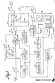
- FIGURE 1 is a block diagram of an exemplary embodiment of an apparatus in accordance with one embodiment of the present invention; and
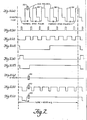
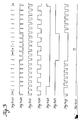
- FIGURES 2a-2i, 3a-3h and 4a and 4b illustrate various waveforms and timing periods associated with operation of the FIGURE 1 apparatus.
- Referring now to the block diagram of FIGURE 1, the video signal which is input to
buffer amplifier 10 is modified with the pseudo-sync pulses or the AGC pulses as discussed above. Thebuffer amplifier 10 may be a unity-gain amplifier which passes the video signal with its added pulses to a sync tip clamp 12. Clamp 12 causes the negative voltage sync tips of both the normally-occurring sync pulses and the added pseudo-sync pulses to be held at a constant negative voltage despite any variation in the average picture signal level, the amplifier gain levels, or other sources of bias. The clamping voltage of the sync tip claim 12 is chosen so that the blanking-level voltage of the video signal at this point is 0 volts, or very close thereto. This fact requires that the overall video signal level be fixed and known. - One of ordinary skill in the art might recognize that a clamp which is activated during the back porch blanking interval appears preferable to a sync tip clamp. This is due to the fact that the overall video level would not need to be known in order to ensure that the blanking level is at 0 volts. Such an alternative clamping mechanism may be used as a feature of the present invention, provided that it is activated only during those back porch intervals which are free of AGC pulses. This added complexity might outweigh the advantages of such an alternative clamp. Hence, the embodiment of present FIGURE 1 merely utilizes a sync tip clamp, as is known to one of ordinary skill in the art. Other elemental devices which are readily recognized and understood by one of ordinary skill in the art, such as the sync separator and the monostable multivibrators, are shown diagramatically only.
- The output of sync tip clamp 12 is fed directly to one of the inputs of electrically- controlled
switch 14. The output selection ofswitch 14 is controlled in accordance with the present invention to blank the positive AGC pulses from the video signal. A complete explanation of this feature is included below. FIGURE 2a illustrates a video signal modified as discussed to inhibit its being recorded, and as output by the sync tip clamp 12.Reference character 16 shows a normal sync pulse, whilereference characters 18 illustrate pseudo-sync pulses in accordance with the "inhibiting" modifications made to a video signal.Reference characters 20 of FIGURES 2a, g, h and i show color burst information included in the normal video signal having color formation. The teachings of the present invention are, of course, equally applicable to a "non-color" video signal. - The dotted box 22 of FIGURE 1 represents a bandpass filter which is resonant at the color subcarrier frequency of the
color burst information 20, and which has a Q-factor of about unity. This, bandpass filter separates the color burst information from the AGC pulses by literally. filtering out the AGC pulses in preference for the bandpass frequency color burst information, and the filter then applies the color burst to a second input ofswitch 14. Waveform 2g illustrates the waveform input to switch 14 from bandpass filter 22. The bandpass filter could, of course, be eliminated for monochrome applications of the present invention. The bandpass filter may be comprised of any known configuration, for example, as shown in FIGURE 1, includingresistor 24,variable inductance 26 andcapacitor 28 to constitute an RLC tuned circuit. - It should be noted that FIGURE 2g clearly illustrates that the bandpass filter 22 outputs a signal level of 0 volts at all times other than the occurrence of color burst information. This "blanking" signal level is useful with
switch 14 in regenerating an AGC-pulse-free video signal by the appropriate selection of theswitch 14 input. This will be discussed more fully below. - The modified input video signal from
buffer amplifier 10 also drives thesync separator 30.Sync separator 30 thus necessarily outputs signals indicative of both thenormal sync pulses 16 and thepseudo-sync pulses 18, as shown in FIGURE 2a. The leading edge of each such sync pulse (of either type: normal or pseudo) triggers themonostable multivibrator 32. The FIGURE 1 embodiment shows a monostable multivibrator as being a 1 microsecond monostable; however, other time periods may be practiced in accordance with the present invention, as is true for virtually all the time periods herein disclosed in the exemplary embodiment. - The output of
monostable multivibrator 32 is illustrated by the waveform of FIGURE 2b,.which shows clearly by comparison with FIGURE 2a that the leading edges of bothnormal sync pulses 16 andpseudo-sync pulses 18 trigger the monostable 32. - As seen in FIGURE 1, the 1 microsecond output pulses from monostable 32 drive the sync tip clamp 12 so that the sync tips are clamped at a given voltage, as discussed above.
- Triggering based on the trailing edge of each sync pulse is used in conjunction with
monostable multivibrator 34, shown in the exemplary embodiment of FIGURE 1 as a 5 microsecond monostable multivibrator. FIGURE 2c illustrates the output ofmonostable multivibrator 34, and clearly shows that the indicated pulse output of monostable 34 is based on the trailing edge of the sync pulses of FIGURE 2a. These 5 microsecond monostable pulses of monostable 34 are used to drive the electrically- controlledswitch 14.Switch 14 is arranged such that the output ofbandpass filter 32 is connected to the output ofswitch 14 whenever the pulses of monostable 34 are high. Conversely, the output of sync tip clamp 12 is connected to the output ofswitch 14 whenever the pulses from monostable 34 are low. - As discussed in the present introduction, the AGC pulses (or positive pulses) occur only following sync pulses. Moreover, as used in the copending applications, the AGC pulses can occur only during the 5 microsecond intervals immediately following sync or pseudo-sync pulses. Therefore, selection of the bandpass filter 22 output during the 5 microsecond intervals immediately following sync pulses causes the output of
switch 14 to be blanked so as to thereby remove theAGC pulses 36 of FIGURE 2(a) from the video signal. The output ofswitch 14 is illustrated by the waveform FIGURE 2h, which shows that theAGC pulses 36 are removed at this point, but that thepseudo-sync pulses 18 are still in place. It should also be noted that the color burstinformation 20 is output by switch 14 (as shown in FIGURE 2h) since this color burst information is output by bandpass filter 22, and since it occurs during the follow-on 5 microsecond intervals during which switch 14 is connected to the bandpass filter 22 output. - The foregoing discussion of a selected portion of FIGURE 1 discloses an apparatus which could be used in isolation apart from the remaining circuitry of FIGURE 1 to remove AGC pulses from a video signal, if that were all that was necessary to enable acceptable video recording of the video signal. In other words, the output of
switch 14, appropriately buffered, could be used as the video output of the FIGURE 1 apparatus, to be input to a . video recorder, if removal of only the AGC pulses was deemed adequate. - The remaining circuitry of exemplary embodiment FIGURE 1 is used primarily in removing pseudo-sync pulses from the modified video signal input to buffer
amplifier 10. Hence, if a video signal modified with the addition of pseudo-sync pulses only (and no added AGC pulses) were processed, switch 14 could be held in its lower position (sync tip clamp input position) at all times to constitute circuitry which only removes pseudo-sync pulses. Of course, the exemplary embodiment of FIGURE 1 removes only pseudo-sync pulses if those are the only sort of pulses added to a video signal. Likewise, the FIGURE 1 apparatus removes only AGC pulses if only AGC pulses are added to a normal video signal. The whole of the FIGURE 1 apparatus, however, removes both added pseudo-sync pulses and added AGC pulses where both are present. - To accomplish the removal of
pseudo-sync pulses 18 from a modified video signal, the video signal frombuffer amplifier 10 is ultimately processed through switch 14 (via either sync tip clamp 12 or bandpass filter 22) and is additionally processed by negative-peak clipper 38. The clipping level ofclipper 38 may be variably set, and is determined by the voltage level applied to the non-inverting input ofoperational amplifier 40.Diode 42 andresistor 44 form a part of a well known clipping configuration foroperational amplifier 40, andresistors circuit 38. - The clipping level of
clipper circuit 38 is variably established by particular selection of the voltage level which is presented to the non-inverting input ofoperational amplifier 40. Digital signals along lead line 50 (or, alternatively, analog signals of appropriate high and low level) are used to control the variable setting of negative voltage clipping foroperational amplifier 40. Generation of a switch control signal onlead line 50 is discussed further below. -
Clipper 38 functions as follows.Operational amplifier 40 will not transmit signal voltage excursions more negative than the voltage at its non-inverting terminal. Therefore, if the voltage at this non-inverting terminal is set to 0 volts, then all sync pulses (e.g., normal sync pulses) and other negative excursions (e.g., pseudo-sync pulses) are removed from the video signal. If, however, this voltage is set to approximately -0.5 volts, then the video signal passes throughclipper 38 without modification since no components of the video signal at the output ofswitch 14 are more negative than -0.3 volts. Refer to the voltage levels indicated in FIGURE 2a. Operation of sync tip clamp 12 enables this precise negative voltage limit setting.Resistors lead line 50 to 0 and -0.5 volts, respectively. - Therefore,
clipper 38 actually functions as a negative-peak clipper circuit only when the signal level onlead line 50 is high. In other words, a "high" signal onlead line 50 is converted byresistors operational amplifier 40. During such an input, all voltages which extend negatively below 0 volts are truncated or clipped from the output ofclipper 38. - The remaining circuitry illustrated in the lower half of FIGURE 1 is concerned with generating an appropriate pulse train on
lead line 50 so as to causeclipper 38 to remove all negative excursions from the video signal except those which are attributable to normal sync pulses. The resulting output ofclipper 38 when operated with such an appropriate pulse train, therefore, is a video signal which has had all added pseudo-sync pulse and AGC pulse pairs (or individual pulses) removed to permit acceptable video recording of the resulting output. - Referring again to FIGURE 1, voltage controlled
oscillator 52 operates at twice the line frequency of the video signal (i.e., 31.468 kilohertz). This oscillator is phase locked by phase detector and filter 54 with the leading edges of the normal sync pulses output bysync separator 30.Divider microsecond monostable 58 function with phase detector and filter 54 in a known fashion to provide the phase lockup for voltage controlledoscillator 52. FIGURE 2d illustrates the line frequency square wave which is output by the voltage controlledoscillator 52 through thedivider 56. In other words, FIGURE 2d illustrates the waveform output bydivider 56. - The negative-going edges of the waveform of FIGURE 2d trigger the pulse outputs of 4
microsecond monostable 58. FIGURE 2e illustrates the waveform which is output by the 4microsecond monostable 58. These pulses shown in FIGURE 2e sample the leading edges of the sync pulses fromsync separator 30 in the phase detector andfilter 54. Transfer characteristics of this phase detector and filter and voltage controlled oscillator are chosen so that theoscillator 52 locks up in the phase relation shown with the various waveforms of FIGURE 2. The detailed design of this phase locked loop is considered well known to one of ordinary skill in the art, and need not therefore be discussed in detail at this point. It should be noted, however, that the phase detectionsystem including monostable 58 and phase detector andfilter 54 prevents the phase locked loop from being disturbed by the occurrence of thepseudo-sync pulses 18. - FIGURE 3a illustrates the timing sequence of various lines in a given video signal field. FIGURE 3b then illustrates a train of normal synchronizing pulses in the vertical sync region of a picture transmission. FIGURE 3g illustrates that waveform needed on
lead line 50 of FIGURE 1 to permit the pulses illustrated in FIGURE 3b to pass without being clipped byclipper circuit 38. Hence, generation of the waveform illustrated in FIGURE 3g is a particular feature of the present invention, and is derived in one exemplary fashion as follows. Of course, any other circuitry which also generates the waveform shown in FIGURE 3g is included within the spirit and scope of the broader teachings of this invention. - The pulses from voltage controlled
oscillator 52 having a frequency twice that of line frequency are counted up by the ten-bit counter 58.Counter 58 is reset to 0 by an output fromfield pulse generator 60.Field pulse generator 60 receives its input fromsync separator 30, and effectively flags the completion of each field of the video signal. See FIGURE 3h which shows a single pulse occurring at the beginning video signal line, designated as line segment 0 in FIGURE 3a. The data lines fromcounter 58 are connected to the address inputs of a read only memory device (ROM) 62, which essentially functions as a state detector in the present apparatus. In other words, read only memory 62 is organized as a 1024 by 2 array, and programmed to provide certain signals at its two respective outputs onlead lines lead line 50, as shown in FIGURE 3g and discussed above, to achieve proper function ofclipper circuit 38. - The time intervals shown in FIGURE 3a are related with the address states in the vertical sync region, and as designated in conjunction with the state detector (ROM) 62. It should be noted that state 0 of the FIGURE 3a intervals corresponds to the field reset pulse of FIGURE 3h.
- Ten microsecond
monostable multivibrator 68 is serially connected in line between the output of voltage controlledoscillator 54 and one input ofOR gate 70. ORgate 70 has as its other input, the output of ANDgate 72. The two inputs of ANDgate 72 are derived from the output of divider 56 (the waveform of FIGURE 2d) and the first output onlead line 64 of state detector 62 (the waveform of FIGURE 3e). The output ofOR gate 70 is then used as one of the inputs for ANDgate 74, with the second output onlead line 66 of state detector 62 (the waveform of FIGURE 3f) serving as the other input thereof. These two signals are "anded" together in ANDgate 74 to obtain onlead line 50 the desired waveform as illustrated in FIGURE 3g. Confirmation of this FIGURE 3g output may be made by one of ordinary skill in the art by comparison inspection of the following four waveforms: FIGURE 2d (which illustrates the output waveform of divider 56); FIGURE 3e (which illustrates the first output of state detector 62 as present on lead line 64); FIGURE 3c (which illustrates the output ofmonostable multivibrator 68 which is input to OR gate 70) and FIGURES 3f and 4(b) (which illustrate ' on two respective time scales the second output of state detector 62 as present on lead line 66). Using these four basic waveforms, and performing the designated operations of ANDgates OR gate 70, the appropriate FIGURE 3g waveform is obtained for proper control ofoperational amplifier 40 to enable deletion of the negative-going pseudo-sync pulses. - The waveforms of FIGURES 3e and 3f, respectively, are reproduced on a broader time scale in the waveforms of FIGURES 4a and 4b. As seen at the bottom of FIGURE 2, the entire time frame of the FIGURE 2 contents includes the equivalent of one video signal line (or 63.55 microseconds). FIGURE 3 discloses a number of "half-lines" 515 through 10. FIGURE 4 marks in dotted lines the vertical blanking interval of twenty lines (or forty half-lines or "states"), and also shows in other dotted lines the time limit boundaries of the FIGURE 3 illustration.
- From FIGURE 4, it may be readily seen that the clipping action of
clipper circuit 38 is disabled for most of the active field except for a few lines on either side of the vertical blanking interval where pseudo-sync pulses may be used. This prevents clipping of normal chroma information which can extend below the blanking level. Theclipper circuit 38 is also disabled during the three lines of the vertical blanking interval during which the normal broad sync pulses occur. - Referring finally to FIGURE 21, the output of
buffer amplifier 76 is illustrated, which output shows retention of thenormal sync pulse 16 and color burstinformation 20, but removal of thepseudo-sync pulses 18 andAGC pulses 36 to thereby permit the making of an acceptable videotape recording of the figure 2i video signal. - As alluded to above, in practice it may be sufficient to remove most of the AGC pulses without the necessity of removing all AGC pulses. Alternatively, and depending on precisely how the original video signal was modified, it may be sufficient to simply remove most of the pseudo-sync pulses. For that reason, the foregoing disclosure explains the several few minor modifications to the FIGURE 1 embodiment which permit the selective removal of either the pseudo-sync pulses or the AGC pulses, as well as any combinations thereof. Likewise, one of ordinary skill in the art will readily appreciate and understand those minor modifications to FIGURE 1 which might be necessary and desirable to cause elimination of some percentage of the AGC pulses or pseudo-sync pulses without the necessity of removing all such pulses. Also, a functional embodiment of this invention might reduce the amplitude of some of the added pulses (e.g., reduce the amplitude of the AGC pulses by 70 percent) as opposed to removing them entirely. All such modifications and variations are intended to fall within the scope and spirit of the present invention, which is further set forth in the appended claims.
Claims (31)
Priority Applications (8)
| Application Number | Priority Date | Filing Date | Title |
|---|---|---|---|
| US06/836,019 US4695901A (en) | 1986-03-04 | 1986-03-04 | Method and apparatus for removing pseudo-sync and/or agc pulses from a video signal |
| GB08721751A GB2195510B (en) | 1986-03-04 | 1987-09-16 | Method and apparatus for removing pseudo-sync and/or agc pulses from a video signal |
| EP87308207A EP0255407B2 (en) | 1986-03-04 | 1987-09-16 | Method and apparatus for removing pseudo-sync and/or automatic gain control pulses from a video signal |
| ES87308207T ES2012486T5 (en) | 1986-03-04 | 1987-09-16 | METHOD AND APPARATUS TO ELIMINATE A PULSE VIDEO SIGNAL OF PSEUDOSINCRONISM AND / OR AUTOMATIC GAIN CONTROL. |
| AT87308207T ATE48356T1 (en) | 1986-03-04 | 1987-09-16 | METHOD AND DEVICE FOR REMOVING PULSE FOR PSEUDOSYNCHRONIZATION AND/OR A.V.R. FROM A VIDEO SIGNAL. |
| DE8787308207T DE3761073D1 (en) | 1986-03-04 | 1987-09-16 | METHOD AND DEVICE FOR REMOVING IMPULSES FOR PSEUDOSYNCHRONIZATION AND / OR A.V.R. FROM A VIDEO SIGNAL. |
| AU78688/87A AU600522B2 (en) | 1986-03-04 | 1987-09-21 | Method and apparatus for removing pseudo-sync and/or AGC pulses from a video signal |
| GR90400086T GR3000351T3 (en) | 1986-03-04 | 1990-02-15 | Method and apparatus for removing pseudo-sync and/or automatic gain control pulses from a video signal |
Applications Claiming Priority (4)
| Application Number | Priority Date | Filing Date | Title |
|---|---|---|---|
| US06/836,019 US4695901A (en) | 1986-03-04 | 1986-03-04 | Method and apparatus for removing pseudo-sync and/or agc pulses from a video signal |
| GB08721751A GB2195510B (en) | 1986-03-04 | 1987-09-16 | Method and apparatus for removing pseudo-sync and/or agc pulses from a video signal |
| EP87308207A EP0255407B2 (en) | 1986-03-04 | 1987-09-16 | Method and apparatus for removing pseudo-sync and/or automatic gain control pulses from a video signal |
| AU78688/87A AU600522B2 (en) | 1986-03-04 | 1987-09-21 | Method and apparatus for removing pseudo-sync and/or AGC pulses from a video signal |
Publications (4)
| Publication Number | Publication Date |
|---|---|
| EP0255407A2 true EP0255407A2 (en) | 1988-02-03 |
| EP0255407A3 EP0255407A3 (en) | 1988-08-10 |
| EP0255407B1 EP0255407B1 (en) | 1989-11-29 |
| EP0255407B2 EP0255407B2 (en) | 1995-03-22 |
Family
ID=39917146
Family Applications (1)
| Application Number | Title | Priority Date | Filing Date |
|---|---|---|---|
| EP87308207A Expired - Lifetime EP0255407B2 (en) | 1986-03-04 | 1987-09-16 | Method and apparatus for removing pseudo-sync and/or automatic gain control pulses from a video signal |
Country Status (8)
| Country | Link |
|---|---|
| US (1) | US4695901A (en) |
| EP (1) | EP0255407B2 (en) |
| AT (1) | ATE48356T1 (en) |
| AU (1) | AU600522B2 (en) |
| DE (1) | DE3761073D1 (en) |
| ES (1) | ES2012486T5 (en) |
| GB (1) | GB2195510B (en) |
| GR (1) | GR3000351T3 (en) |
Cited By (2)
| Publication number | Priority date | Publication date | Assignee | Title |
|---|---|---|---|---|
| SG85602A1 (en) * | 1990-11-13 | 2002-01-15 | Macrovision Corp | Method and apparatus for disabling anti-copy protection system in video signals |
| EP0923240B1 (en) * | 1993-05-17 | 2012-11-14 | Rovi Solutions Corporation | Method and apparatus for defeating a video copy protection |
Families Citing this family (49)
| Publication number | Priority date | Publication date | Assignee | Title |
|---|---|---|---|---|
| USRE40689E1 (en) * | 1983-11-23 | 2009-03-31 | Macrovision Corporation | Method and apparatus for disabling anti-copy protection system in video signals |
| US5130810A (en) * | 1983-11-23 | 1992-07-14 | Macrovision Corporation | Method and apparatus for processing a video signal so as to prohibit the making of acceptable videotape recordings |
| US4790011A (en) * | 1986-10-17 | 1988-12-06 | Zenith Electronics Corporation | Auto clamp for modulator for suppressed sync signals |
| US4803552A (en) * | 1986-12-03 | 1989-02-07 | Xantech Corporation | Vertical blanking interval standardizer circuit |
| US4777648A (en) * | 1986-12-15 | 1988-10-11 | Trw Inc. | Line tilt compensation method and apparatus |
| CA1337496C (en) * | 1987-07-29 | 1995-10-31 | Yasunori Takahashi | Copy protected pre-recorded videotape |
| US5220426A (en) * | 1988-02-05 | 1993-06-15 | Karlock James A | Circuitry for removing information from, or modifying information in, the vertical interval of a television signal |
| US4914694A (en) * | 1988-04-11 | 1990-04-03 | Eidak Corporation | Modifying a television signal to inhibit recording/reproduction |
| US5142575A (en) * | 1988-04-29 | 1992-08-25 | Scientific-Atlanta, Inc. | Method and apparatus for improving video scrambling and employing split sync pulses |
| US4924498A (en) * | 1988-04-29 | 1990-05-08 | Scientific Atlanta, Inc. | Method and apparatus for improving video scrambling and employing split snyc pulses |
| US4912691A (en) * | 1988-08-01 | 1990-03-27 | Raymond Jones | Video stabilizer |
| DE8812594U1 (en) * | 1988-10-04 | 1988-11-24 | Ellerbrok, Ingrid, 1000 Berlin, De | |
| US5177787A (en) * | 1989-05-01 | 1993-01-05 | Scientific-Atlanta, Inc | Scrambler with self-calibration |
| GB2233184B (en) * | 1989-05-26 | 1993-05-19 | Pioneer Electronic Corp | Catv terminal unit having an improved descrambling operation |
| US5003590A (en) * | 1989-12-18 | 1991-03-26 | Eidak Corporation | Encoding an optical video disc to inhibit video tape recording |
| JPH03125576U (en) * | 1990-03-29 | 1991-12-18 | ||
| NL9000951A (en) * | 1990-04-20 | 1991-11-18 | Copyguard Enterprises | METHOD AND APPARATUS FOR PREVENTING UNLAWFUL TRANSMISSION OF IMAGE SIGNALS |
| EP0473293B1 (en) * | 1990-08-03 | 1996-09-25 | Canon Kabushiki Kaisha | Synchronous signal detection circuit and synchronous signal detection apparatus having the same |
| JPH04115790A (en) * | 1990-09-05 | 1992-04-16 | Sharp Corp | Synchronizing circuit |
| US5155767A (en) * | 1991-11-12 | 1992-10-13 | Noller Robert R | Method and apparatus for manufacturing pre-recorded videotape programs |
| US5410364A (en) * | 1992-01-15 | 1995-04-25 | Karlock; James A. | Method and apparatus for removing AGC pulses and other undesirable signals from a video signal |
| KR940008492B1 (en) * | 1992-03-23 | 1994-09-15 | 삼성전자 주식회사 | Error action preventing circuit of character producing circuit |
| US5394470A (en) * | 1992-08-24 | 1995-02-28 | Eidak Corporation | Horizontal pulse augmentation of a video signal |
| JP3319141B2 (en) * | 1994-03-27 | 2002-08-26 | ソニー株式会社 | Image signal processing device |
| JPH07307900A (en) * | 1994-05-12 | 1995-11-21 | Funai Electric Co Ltd | External input signal processing circuit in television receiver with integrated vtr |
| US5737417A (en) * | 1995-04-24 | 1998-04-07 | Technicolor Videocassette, Inc. | Videotape anti-copying encryption scheme |
| US7065211B1 (en) * | 1995-07-21 | 2006-06-20 | Sony Corporation | Signal reproducing/recording/transmitting method and apparatus and signal recording medium |
| KR100489145B1 (en) * | 1995-10-17 | 2005-09-14 | 매크로비젼 코포레이션 | Method and apparatus for digitally removing the effects of video anti-copy signals from video signals |
| US5978480A (en) * | 1996-08-30 | 1999-11-02 | Vtech Communications, Ltd. | System for scrambling and descrambling video signals by altering synchronization patterns |
| US6058191A (en) * | 1997-02-04 | 2000-05-02 | Macrovision Corp | Method and apparatus for modifying the envelope of a RF carrier signal to remove copy protection signals therefrom |
| US6836549B1 (en) * | 1998-09-02 | 2004-12-28 | Macrovision Corporation | Method and apparatus for synthesizing and reducing the effects of video copy protection signals |
| US6191725B1 (en) * | 1999-08-30 | 2001-02-20 | Her Majesty The Queen In Right Of Canada, As Represented By Minister Of National Defence Of Her Majesty's Canadian Government | Automatic gain control for digital radar intercept receivers |
| US6826352B1 (en) | 2000-03-29 | 2004-11-30 | Macrovision Corporation | Dynamic video copy protection system |
| US6865337B1 (en) | 2000-08-08 | 2005-03-08 | Conexant Systems, Inc. | System and method for detecting modifications of video signals designed to prevent copying by traditional video tape recorders |
| US7110042B1 (en) * | 2001-11-07 | 2006-09-19 | Pixelworks, Inc. | Synchronization signal decoder and associated method |
| US20050111661A1 (en) * | 2002-02-01 | 2005-05-26 | Arie Wijnen | Anti-copy protection for a video signal |
| GB2390247B (en) | 2002-06-28 | 2006-04-12 | Dwight Cavendish Systems Ltd | An improved method and apparatus for providing an anti-copy video signal |
| US7376337B2 (en) * | 2002-09-30 | 2008-05-20 | Matsushita Electric Industrial Co., Ltd. | Video signal recording apparatus for copyrighted works |
| GB0312985D0 (en) * | 2003-06-05 | 2003-07-09 | Dwight Cavendish Systems Ltd | Digital processing disruption systems |
| JP4424929B2 (en) * | 2003-07-15 | 2010-03-03 | パイオニア株式会社 | Information recording medium, information reproducing apparatus and information reproducing method |
| GB2419220B (en) | 2004-10-13 | 2009-06-03 | Dwight Cavendish Systems Ltd | Audio copy protection system |
| CA2763846A1 (en) * | 2004-10-28 | 2006-05-11 | Rovi Solutions Corporation | Content management for high definition television |
| US7792293B2 (en) * | 2005-05-06 | 2010-09-07 | Rovi Solutions Corporation | Method and apparatus for modifying a subsequently generated control command in a content control system |
| US8144250B2 (en) * | 2006-12-26 | 2012-03-27 | John Louis Kotos | Microcontroller-based multi-format video AGC/sync loop regulator |
| US8428258B2 (en) * | 2007-05-02 | 2013-04-23 | Rovi Technologies Corporation | Method and apparatus for providing content control via detection of modifications to a signal |
| US20080309816A1 (en) * | 2007-06-15 | 2008-12-18 | Macrovision Corporation | Television content control system and method with cross-platform capability |
| US8280049B2 (en) * | 2008-08-27 | 2012-10-02 | Rovi Solutions Corporation | Method and apparatus for synthesizing copy protection for reducing/defeating the effectiveness or capability of a circumvention device |
| US8374490B2 (en) * | 2010-02-24 | 2013-02-12 | Rovi Technologies Corporation | Method and apparatus for receiving metadata, EPG, or IPG signals in an integrated circuit for control purposes |
| US8306403B2 (en) * | 2010-03-29 | 2012-11-06 | Rovi Technologies Corporation | Content control via guide data and/or metadata |
Citations (7)
| Publication number | Priority date | Publication date | Assignee | Title |
|---|---|---|---|---|
| US3081376A (en) * | 1959-03-23 | 1963-03-12 | Zenith Radio Corp | Subscription television system |
| US3439113A (en) * | 1963-11-15 | 1969-04-15 | Teleglobe Pay Tv System Inc | Subscription television communication system |
| US3478166A (en) * | 1963-09-09 | 1969-11-11 | Intern Telemeter Corp | Cryptographic subscription television system with grey sync and dual mode augmenting signals |
| US3530232A (en) * | 1966-06-17 | 1970-09-22 | Intern Telemeter Corp | Subscription television system |
| US4319273A (en) * | 1979-10-26 | 1982-03-09 | Rca Corporation | Television signal with encoded synchronizing signals |
| US4390898A (en) * | 1981-03-19 | 1983-06-28 | Northern Telecom Limited | Scrambling and unscrambling video signals in a pay TV system |
| EP0199553A2 (en) * | 1985-04-17 | 1986-10-29 | Macrovision Corporation | Method and apparatus for processing a video signal so as to prohibit the making of acceptable video tape recordings thereof |
Family Cites Families (25)
| Publication number | Priority date | Publication date | Assignee | Title |
|---|---|---|---|---|
| US3029306A (en) * | 1958-05-19 | 1962-04-10 | Ampex | Video recording system and method and processing amplifier network |
| US3197559A (en) * | 1960-10-25 | 1965-07-27 | Sony Corp | Magnetic recording and reproducing system with mechanical generation of synchronizing information |
| GB1068881A (en) * | 1964-04-07 | 1967-05-17 | R & R Res Ltd | Improvements in and relating to television apparatus |
| CA935915A (en) * | 1964-08-01 | 1973-10-23 | Sony Corporation | Video magnetic recording and reproducing system |
| GB1114977A (en) * | 1965-01-23 | 1968-05-22 | Sony Corp | Magnetic recording and playback system |
| US3446914A (en) * | 1965-10-12 | 1969-05-27 | Minnesota Mining & Mfg | Audio and video recording with phase modulated audio pulse on horizontal back porch |
| US3470315A (en) * | 1965-11-18 | 1969-09-30 | Sony Corp | Skip field recording and reproducing system with modified vertical sync signal |
| US3470316A (en) * | 1965-11-18 | 1969-09-30 | Sony Corp | Skip field recording and reproducing system with vertical sync signal generation |
| US3488433A (en) * | 1965-12-03 | 1970-01-06 | Akai Electric | Video tape recorder employing a delay of the horizontal sync signals to facilitate separation from the video signal |
| GB1128591A (en) * | 1965-12-11 | 1968-09-25 | ||
| GB1149626A (en) * | 1966-02-08 | 1969-04-23 | Akai Electric | Magnetic recording and reproducing system |
| US3504116A (en) * | 1966-02-25 | 1970-03-31 | Akai Electric | Magnetic recording system with a disabled bias oscillator during the vertical synchronization interval |
| US3517127A (en) * | 1966-03-21 | 1970-06-23 | Fowler Allan R | Sync generator and recording system including same |
| JPS6052625B2 (en) * | 1976-03-22 | 1985-11-20 | ソニー株式会社 | Recorded recording medium and its production method |
| JPS52114313A (en) * | 1976-03-23 | 1977-09-26 | Sony Corp | Recorded medium and production method therefor |
| US4121242A (en) * | 1976-04-20 | 1978-10-17 | Janko Mike A | Video processor providing sync stripping and reinsertion |
| JPS5389715A (en) * | 1977-01-19 | 1978-08-07 | Sony Corp | Transmitting method for luminance signal |
| US4213149A (en) * | 1978-12-26 | 1980-07-15 | Janko Mike A | Apparatus for preventing video tape duplication |
| GB2055501A (en) * | 1979-08-03 | 1981-03-04 | Ivs Uk Ltd | Video tape recording apparatus |
| JPS57200811A (en) * | 1981-06-04 | 1982-12-09 | Fuji Heavy Ind Ltd | Crank angle detecting device |
| US4571642A (en) * | 1981-08-24 | 1986-02-18 | Hofstein Steven R | Method of and apparatus for modifying a video signal to prevent the unauthorized recording and reproduction thereof |
| JPS58123289A (en) * | 1982-01-18 | 1983-07-22 | Shinano Kikaku:Kk | Recording method for duplication-protected video- recorded magnetic tape |
| US4467358A (en) * | 1982-02-09 | 1984-08-21 | Switsen Henry N | Video tape recorder signal processor |
| AU2494384A (en) * | 1983-02-09 | 1984-08-30 | Societe Internationale De Service A L'Exportation Dite Sisex & Specialites Electro Physiques Sep & Recherches Integrees Au Marketing Rim | Device for the protection of magnetic tapes, or other recording media, or television or radio broadcasting against an authorized reading and/or reproduction |
| WO1985002293A1 (en) * | 1983-11-21 | 1985-05-23 | Haute Securite Video Hsv S.A. | Antipiracy device and method for cinematographic and video carriers |
-
1986
- 1986-03-04 US US06/836,019 patent/US4695901A/en not_active Expired - Lifetime
-
1987
- 1987-09-16 DE DE8787308207T patent/DE3761073D1/en not_active Expired - Lifetime
- 1987-09-16 EP EP87308207A patent/EP0255407B2/en not_active Expired - Lifetime
- 1987-09-16 AT AT87308207T patent/ATE48356T1/en not_active IP Right Cessation
- 1987-09-16 GB GB08721751A patent/GB2195510B/en not_active Expired
- 1987-09-16 ES ES87308207T patent/ES2012486T5/en not_active Expired - Lifetime
- 1987-09-21 AU AU78688/87A patent/AU600522B2/en not_active Expired
-
1990
- 1990-02-15 GR GR90400086T patent/GR3000351T3/en unknown
Patent Citations (7)
| Publication number | Priority date | Publication date | Assignee | Title |
|---|---|---|---|---|
| US3081376A (en) * | 1959-03-23 | 1963-03-12 | Zenith Radio Corp | Subscription television system |
| US3478166A (en) * | 1963-09-09 | 1969-11-11 | Intern Telemeter Corp | Cryptographic subscription television system with grey sync and dual mode augmenting signals |
| US3439113A (en) * | 1963-11-15 | 1969-04-15 | Teleglobe Pay Tv System Inc | Subscription television communication system |
| US3530232A (en) * | 1966-06-17 | 1970-09-22 | Intern Telemeter Corp | Subscription television system |
| US4319273A (en) * | 1979-10-26 | 1982-03-09 | Rca Corporation | Television signal with encoded synchronizing signals |
| US4390898A (en) * | 1981-03-19 | 1983-06-28 | Northern Telecom Limited | Scrambling and unscrambling video signals in a pay TV system |
| EP0199553A2 (en) * | 1985-04-17 | 1986-10-29 | Macrovision Corporation | Method and apparatus for processing a video signal so as to prohibit the making of acceptable video tape recordings thereof |
Cited By (2)
| Publication number | Priority date | Publication date | Assignee | Title |
|---|---|---|---|---|
| SG85602A1 (en) * | 1990-11-13 | 2002-01-15 | Macrovision Corp | Method and apparatus for disabling anti-copy protection system in video signals |
| EP0923240B1 (en) * | 1993-05-17 | 2012-11-14 | Rovi Solutions Corporation | Method and apparatus for defeating a video copy protection |
Also Published As
| Publication number | Publication date |
|---|---|
| AU600522B2 (en) | 1990-08-16 |
| US4695901B1 (en) | 1990-10-02 |
| ATE48356T1 (en) | 1989-12-15 |
| DE3761073D1 (en) | 1990-01-04 |
| GB2195510B (en) | 1988-12-07 |
| EP0255407B2 (en) | 1995-03-22 |
| ES2012486T5 (en) | 1995-08-16 |
| AU7868887A (en) | 1989-03-23 |
| EP0255407B1 (en) | 1989-11-29 |
| ES2012486B3 (en) | 1990-04-01 |
| GB2195510A (en) | 1988-04-07 |
| GR3000351T3 (en) | 1991-06-07 |
| US4695901A (en) | 1987-09-22 |
| EP0255407A3 (en) | 1988-08-10 |
| GB8721751D0 (en) | 1987-10-21 |
Similar Documents
| Publication | Publication Date | Title |
|---|---|---|
| EP0255407B1 (en) | Method and apparatus for removing pseudo-sync and/or automatic gain control pulses from a video signal | |
| CA1256558A (en) | Method and apparatus for processing a video signal so as to prohibit the making of acceptable video tape recordings thereof | |
| BG63587B1 (en) | Method and device for removing the effects of colour package of a videosignal modifications | |
| KR880001922B1 (en) | Non-copiable video tape recording system | |
| US6600873B1 (en) | Method and apparatus for detecting modified color burst signals to prevent the copying of a video program | |
| US5661801A (en) | Method and apparatus for stabilizing and brightening prerecorded TV signals encoded with copy protection | |
| US3408457A (en) | Clamped video dropout compensator | |
| US3863022A (en) | Television signal clocked delay line for delay by an integer number of horizontal scanning lines driven by a pilot signal | |
| US4580166A (en) | Synchronizing signal separator network | |
| CA1292566C (en) | Method and apparatus for removing pseudo-sync and/or agc pulses from a video signal | |
| GB1509336A (en) | Colour video reproducing apparatus | |
| DE4104773C2 (en) | Time difference correction circuit for brightness and chrominance signals | |
| DE3942204C1 (en) | ||
| DE3926481C2 (en) | ||
| US4709268A (en) | Automatic frequency pulling circuit | |
| DE2908501C2 (en) | ||
| JP3092938B2 (en) | Digital synchronization circuit for image display | |
| JP2512008B2 (en) | Method and apparatus for removing pseudo sync pulses and / or AGC pulses from a video signal | |
| US5034815A (en) | Separation circuit for imposing detection timings of a synchronous signal used in a video apparatus | |
| NZ221818A (en) | Removing pseudo-sync pulses from video signal | |
| EP0525028A1 (en) | A method and an apparatus for preventing unauthorized copying of video signals on tape | |
| DE4018956C2 (en) | video | |
| DE4227175A1 (en) | CIRCUIT ARRANGEMENT FOR AUTOMATIC SWITCHING TO RECORDING OPERATION FOR AN IMAGE RECORDING AND / OR REPLAYING DEVICE | |
| US4400733A (en) | Synchronizing pulse separator | |
| JPH0411434Y2 (en) |
Legal Events
| Date | Code | Title | Description |
|---|---|---|---|
| PUAI | Public reference made under article 153(3) epc to a published international application that has entered the european phase |
Free format text: ORIGINAL CODE: 0009012 |
|
| AK | Designated contracting states |
Kind code of ref document: A2 Designated state(s): AT BE CH DE ES FR GB GR IT LI LU NL SE |
|
| PUAL | Search report despatched |
Free format text: ORIGINAL CODE: 0009013 |
|
| AK | Designated contracting states |
Kind code of ref document: A3 Designated state(s): AT BE CH DE ES FR GB GR IT LI LU NL SE |
|
| 17P | Request for examination filed |
Effective date: 19880919 |
|
| 17Q | First examination report despatched |
Effective date: 19890208 |
|
| GRAA | (expected) grant |
Free format text: ORIGINAL CODE: 0009210 |
|
| AK | Designated contracting states |
Kind code of ref document: B1 Designated state(s): AT BE CH DE ES FR GR IT LI LU NL SE |
|
| REF | Corresponds to: |
Ref document number: 48356 Country of ref document: AT Date of ref document: 19891215 Kind code of ref document: T |
|
| ITF | It: translation for a ep patent filed |
Owner name: BARZANO' E ZANARDO MILANO S.P.A. |
|
| REF | Corresponds to: |
Ref document number: 3761073 Country of ref document: DE Date of ref document: 19900104 |
|
| ET | Fr: translation filed | ||
| PLBI | Opposition filed |
Free format text: ORIGINAL CODE: 0009260 |
|
| PLBI | Opposition filed |
Free format text: ORIGINAL CODE: 0009260 |
|
| REG | Reference to a national code |
Ref country code: GR Ref legal event code: FG4A Free format text: 3000351 |
|
| 26 | Opposition filed |
Opponent name: MACROVISION CORPORATION Effective date: 19900821 |
|
| 26 | Opposition filed |
Opponent name: MACROVISION CORPORATION Effective date: 19900821 Opponent name: VSA LTD Effective date: 19900824 |
|
| NLR1 | Nl: opposition has been filed with the epo |
Opponent name: MACROVISION CORPORATION. |
|
| NLR1 | Nl: opposition has been filed with the epo |
Opponent name: VSA LTD. |
|
| ITTA | It: last paid annual fee | ||
| EPTA | Lu: last paid annual fee | ||
| ITF | It: translation for a ep patent filed |
Owner name: BARZANO' E ZANARDO MILANO S.P.A. |
|
| PGFP | Annual fee paid to national office [announced via postgrant information from national office to epo] |
Ref country code: LU Payment date: 19940901 Year of fee payment: 8 |
|
| EAL | Se: european patent in force in sweden |
Ref document number: 87308207.7 |
|
| PUAH | Patent maintained in amended form |
Free format text: ORIGINAL CODE: 0009272 |
|
| STAA | Information on the status of an ep patent application or granted ep patent |
Free format text: STATUS: PATENT MAINTAINED AS AMENDED |
|
| 27A | Patent maintained in amended form |
Effective date: 19950322 |
|
| AK | Designated contracting states |
Kind code of ref document: B2 Designated state(s): AT BE CH DE ES FR GR IT LI LU NL SE |
|
| REG | Reference to a national code |
Ref country code: CH Ref legal event code: AEN |
|
| NLR2 | Nl: decision of opposition | ||
| PG25 | Lapsed in a contracting state [announced via postgrant information from national office to epo] |
Ref country code: GR Free format text: THE PATENT HAS BEEN ANNULLED BY A DECISION OF A NATIONAL AUTHORITY Effective date: 19950614 |
|
| ET3 | Fr: translation filed ** decision concerning opposition | ||
| REG | Reference to a national code |
Ref country code: ES Ref legal event code: DC2A Kind code of ref document: T5 Effective date: 19950816 |
|
| REG | Reference to a national code |
Ref country code: GR Ref legal event code: FG4A Free format text: 3016430 |
|
| NLR3 | Nl: receipt of modified translations in the netherlands language after an opposition procedure | ||
| PG25 | Lapsed in a contracting state [announced via postgrant information from national office to epo] |
Ref country code: LU Free format text: LAPSE BECAUSE OF NON-PAYMENT OF DUE FEES Effective date: 19950916 |
|
| REG | Reference to a national code |
Ref country code: CH Ref legal event code: PFA Owner name: MACROVISION CORPORATION Free format text: MACROVISION CORPORATION#1035 SARATOGA-SUNNYVALE ROAD#SAN JOSE/CA (US) -TRANSFER TO- MACROVISION CORPORATION#2830 DE LA CRUZ BOULEVARD#SANTA CLARA, CA 95050 (US) |
|
| REG | Reference to a national code |
Ref country code: FR Ref legal event code: CA |
|
| PGFP | Annual fee paid to national office [announced via postgrant information from national office to epo] |
Ref country code: GR Payment date: 20060822 Year of fee payment: 20 |
|
| PGFP | Annual fee paid to national office [announced via postgrant information from national office to epo] |
Ref country code: NL Payment date: 20060903 Year of fee payment: 20 |
|
| PGFP | Annual fee paid to national office [announced via postgrant information from national office to epo] |
Ref country code: FR Payment date: 20060908 Year of fee payment: 20 |
|
| PGFP | Annual fee paid to national office [announced via postgrant information from national office to epo] |
Ref country code: CH Payment date: 20060913 Year of fee payment: 20 Ref country code: AT Payment date: 20060913 Year of fee payment: 20 |
|
| PGFP | Annual fee paid to national office [announced via postgrant information from national office to epo] |
Ref country code: DE Payment date: 20060914 Year of fee payment: 20 |
|
| PGFP | Annual fee paid to national office [announced via postgrant information from national office to epo] |
Ref country code: IT Payment date: 20060930 Year of fee payment: 20 |
|
| PGFP | Annual fee paid to national office [announced via postgrant information from national office to epo] |
Ref country code: ES Payment date: 20061023 Year of fee payment: 20 |
|
| PGFP | Annual fee paid to national office [announced via postgrant information from national office to epo] |
Ref country code: BE Payment date: 20061110 Year of fee payment: 20 |
|
| REG | Reference to a national code |
Ref country code: CH Ref legal event code: PL |
|
| NLV7 | Nl: ceased due to reaching the maximum lifetime of a patent |
Effective date: 20070916 |
|
| EUG | Se: european patent has lapsed | ||
| REG | Reference to a national code |
Ref country code: ES Ref legal event code: FD2A Effective date: 20070917 |
|
| BE20 | Be: patent expired |
Owner name: *MACROVISION CORP. Effective date: 20070916 |
|
| PG25 | Lapsed in a contracting state [announced via postgrant information from national office to epo] |
Ref country code: NL Free format text: LAPSE BECAUSE OF EXPIRATION OF PROTECTION Effective date: 20070916 Ref country code: ES Free format text: LAPSE BECAUSE OF EXPIRATION OF PROTECTION Effective date: 20070917 |
|
| PGFP | Annual fee paid to national office [announced via postgrant information from national office to epo] |
Ref country code: SE Payment date: 20060906 Year of fee payment: 20 |