EP0256710A2 - Fiber optic cable preparation tool and method of preparing fiber optic cable for termination with a fiber optic connector - Google Patents
Fiber optic cable preparation tool and method of preparing fiber optic cable for termination with a fiber optic connector Download PDFInfo
- Publication number
- EP0256710A2 EP0256710A2 EP87306712A EP87306712A EP0256710A2 EP 0256710 A2 EP0256710 A2 EP 0256710A2 EP 87306712 A EP87306712 A EP 87306712A EP 87306712 A EP87306712 A EP 87306712A EP 0256710 A2 EP0256710 A2 EP 0256710A2
- Authority
- EP
- European Patent Office
- Prior art keywords
- fiber
- fiber optic
- cable
- tool
- buffer
- Prior art date
- Legal status (The legal status is an assumption and is not a legal conclusion. Google has not performed a legal analysis and makes no representation as to the accuracy of the status listed.)
- Withdrawn
Links
Images


Classifications
-
- G—PHYSICS
- G02—OPTICS
- G02B—OPTICAL ELEMENTS, SYSTEMS OR APPARATUS
- G02B6/00—Light guides; Structural details of arrangements comprising light guides and other optical elements, e.g. couplings
- G02B6/44—Mechanical structures for providing tensile strength and external protection for fibres, e.g. optical transmission cables
- G02B6/4479—Manufacturing methods of optical cables
-
- G—PHYSICS
- G02—OPTICS
- G02B—OPTICAL ELEMENTS, SYSTEMS OR APPARATUS
- G02B6/00—Light guides; Structural details of arrangements comprising light guides and other optical elements, e.g. couplings
- G02B6/24—Coupling light guides
- G02B6/36—Mechanical coupling means
- G02B6/38—Mechanical coupling means having fibre to fibre mating means
- G02B6/3807—Dismountable connectors, i.e. comprising plugs
- G02B6/3887—Anchoring optical cables to connector housings, e.g. strain relief features
- G02B6/3888—Protection from over-extension or over-compression
-
- Y—GENERAL TAGGING OF NEW TECHNOLOGICAL DEVELOPMENTS; GENERAL TAGGING OF CROSS-SECTIONAL TECHNOLOGIES SPANNING OVER SEVERAL SECTIONS OF THE IPC; TECHNICAL SUBJECTS COVERED BY FORMER USPC CROSS-REFERENCE ART COLLECTIONS [XRACs] AND DIGESTS
- Y10—TECHNICAL SUBJECTS COVERED BY FORMER USPC
- Y10T—TECHNICAL SUBJECTS COVERED BY FORMER US CLASSIFICATION
- Y10T29/00—Metal working
- Y10T29/49—Method of mechanical manufacture
- Y10T29/49002—Electrical device making
- Y10T29/49117—Conductor or circuit manufacturing
- Y10T29/49169—Assembling electrical component directly to terminal or elongated conductor
Definitions
- This invention relates to a tool for use in preparing a fiber optic cable for termination with a fiber optic connector.
- the invention also relates to the method of preparing the fiber optic cable to permit simple and easy termination with a fiber optic connector.
- a typical fiber optic cable generally consists of a centrally located optical fiber which is covered by a buffer layer, typically of silicone or some other like material. This buffered fiber is in turn covered by a layer of high tensile strength fibers which serve to protect the optical fiber. Typically these high tensile strength fibers are those commerically available under the trade name KevlarTM. The strength fiber covered optical fiber is in turn surrounded by a plastic jacket.
- the jacket In order to terminate the fiber optic cable with a fiber optic connector it is necessary to strip the jacket to a specific length to expose the strength fibers and the buffered fiber.
- the buffered fiber is stripped of buffer material to accomodate attachment of the optical fiber to the mating end of the connector.
- the strength fibers are prepared for attachment in a crimping arrangement to structural parts of the connector. As can be appreciated this involves the use of many tools and many steps resulting in a considerable waste of time and motion on the part of the worker.
- a fiber optic cable is connected to the rear end of a fiber optic connector by inserting a metal sleeve as a support or base for a terminated portion of the strength layer and outer sheath.
- the metal sleeve is received between the buffer covered fiber and the strength layer with the cable then being inserted into the connector and an outer crimp sleeve being crimped onto the outer sheath of the cable thereby holding the outer sheath and strength layers between the metal sleeve support and the outer crimp sleeve.
- a tool for preparing a fiber optic cable for termination with a fiber optic connector is provided.
- the fiber optic cable is a cable of the type having, in a concentric arrangement, from the exterior to the center thereof, an outer protective cover, a layer of strength members and a buffer layer covered fiber.
- the tool comprises an elongate first member which has a longitudinal passage extending therethrough.
- the member has one end which is of clampable construction and another end whose exterior surface is of frusto-conical shape.
- Clamp means are provided for clamping the one end of the first member onto a fiber optic cable to be received within the longitudinal passage thereof and held by said first member.
- a second clamp member having a longitudinal passage therethrough is provided and is of such a size that the second clamp member can be received on the exterior of the frusto-conical end of the first member in a manner for holding strength members of a fiber optic cable securely against the outer surface of the frusto-conical end of the first member.
- Sleeve press means cooperates with the above described elements and includes a longitudinal passage extending therethrough of a size sufficient to permit a buffer covered fiber of a fiber optic cable to pass therethrough.
- a recess is provided at one end of the sleeve press means, which recess is of predetermined depth for receiving the above discussed inner crimp sleeve, which is mounted surrounding the buffered cover optical fiber, in abutment against the one end of the sleeve press means in the recess in a manner such that the inner crimp sleeve can be forced into the cable between strength layer and the buffer layer to provide a support for an outer crimp sleeve of a connector with which the fiber optic cable is to be terminated.
- a method of preparing the fiber optic cable once the fiber optic cable is mounted in the first member, the sheath extending from the frusto-conical end thereof is stripped off. The strength members are then folded back over the frusto-conical outer surface and the second member is employed to clamp such strength members thereon. An inner crimp sleeve is then received over the buffered cover fiber and the sleeve press means is employed to force the inner sleeve into the region between the buffered cover fiber and the strength members.
- sleeve press means is engaged by an O-ring arrangement of the second member and is of predetermined length to define the desired length of the buffered cover fiber to be received within a connector.
- the buffer is then stripped leaving only the exposed fiber which is to be mounted at the mating end of the connector. Thereafter, the sleeve press means is removed from the combined tool arrangement and the strength fibers are cut at the point at which they are folded back. After this step the entire tool is disassembled and the cable removed therefrom resulting in a cable which has been prepared for quick and easy termination with a fiber optic connector.
- the cable preparation tool 1 includes a first body or member 3 which has a rear portion 5 and a front portion 13.
- the rear portion consists of a split section having a longitudinal passage 9 therethrough which split portion can have the various parts 7 thereof compressible together by a slidable clamp member 11.
- a grip region 17 of conventional construction as will be readily apparent to those of ordinary skill in the art is provided.
- the front portion of the rear body 3 includes a frusto-conical outer surface 13 terminating at an end 15 at which the longitudinal opening 9 opens to the exterior.
- a second, front body or member 19 is also provided having a passage 25 therethrough which corresponds is size and shape to the frusto-conical shaped front portion 13.
- This front body 19 includes a gripping region 27 as well as a forward extension 21 constructed for receiving an O-ring 23 thereon.
- the front body 19 is receivable over the front surface 13 in a manner such as to clamp strength members of a fiber optic cable between the inner walls of the passage 25 and the outer surface of the frusto-conical front portion 13.
- a third body or member 29, in this case a press body member 29 includes a longitudinal passage 33 extending therethrough which is of a size sufficient to permit a buffer covered fiber to extend through the body 29 and out an opening at the front face 31 thereof.
- a recess 35 is of sufficient size to fit over the front end 21 of body 19 and is held thereon by means of O-ring 23.
- the length A of body or member 29 is such that it corresponds to a predetermined size section of fiber which is to be left covered with the buffer layer in a connector and all fiber extending beyond the front end 31 of said body 29 is to be stripped of the buffer layer for later termination within a fiber optic connector.
- a fiber optic cable 37 having an outer sheath 39 is inserted from the rear into the rear body 3.
- the clamp member 11 is slid rearwardly to cause the individual split portions 7 to clamp the cable 37 therein.
- the front of the cable extends beyond the front end 15 of the rear body and the outer sheath 39 is cut at the very front end 15 of said front body with the strength members 41 of a cable extending therefrom.
- these strength members 41 are folded rearwardly over the frusto-conical surface 13 and the front body 19 is slid thereover to clamp said strength members 41 onto said frusto-conical surface 13.
- the buffer covered fiber extends from the front.
- an inner sleeve 45 is then received over the buffer covered fiber 43 and moved in the direction C by means of the press body 29 which is moved in the direction B which is coincident with the direction C.
- This press body 29 serves to force the sleeve 45 into the region between the strength members 41 and the buffer cover fiber 43.
- this front press body 29 is received on the front end of body 19 and held thereon so that from the front end 31 of the press body, the buffer can be stripped from the buffer covered fiber 43.
- the front body 29 is removed and the strength fibers 41 are cut at said front end 15 of the rear body and the entire assembly is then disassembled and the cable has thus been prepared for termination, for example, with the connector of said copending application previously referenced.
- this tool is made of a metal, for example, stainless steel or other conventional material well known to those of ordinary skill in the art.
Abstract
Description
- This invention relates to a tool for use in preparing a fiber optic cable for termination with a fiber optic connector. The invention also relates to the method of preparing the fiber optic cable to permit simple and easy termination with a fiber optic connector.
- A typical fiber optic cable generally consists of a centrally located optical fiber which is covered by a buffer layer, typically of silicone or some other like material. This buffered fiber is in turn covered by a layer of high tensile strength fibers which serve to protect the optical fiber. Typically these high tensile strength fibers are those commerically available under the trade name Kevlar™. The strength fiber covered optical fiber is in turn surrounded by a plastic jacket.
- In order to terminate the fiber optic cable with a fiber optic connector it is necessary to strip the jacket to a specific length to expose the strength fibers and the buffered fiber. The buffered fiber is stripped of buffer material to accomodate attachment of the optical fiber to the mating end of the connector. Furthermore, the strength fibers are prepared for attachment in a crimping arrangement to structural parts of the connector. As can be appreciated this involves the use of many tools and many steps resulting in a considerable waste of time and motion on the part of the worker.
- In one specific arrangement such as disclosed in our European Patent Application No.86108829.2 filed 28 June 1986, and which disclosure is specifically incorporated by reference herein, a fiber optic cable is connected to the rear end of a fiber optic connector by inserting a metal sleeve as a support or base for a terminated portion of the strength layer and outer sheath. The metal sleeve is received between the buffer covered fiber and the strength layer with the cable then being inserted into the connector and an outer crimp sleeve being crimped onto the outer sheath of the cable thereby holding the outer sheath and strength layers between the metal sleeve support and the outer crimp sleeve. In preparing a cable for this particular type of arrangement, this becomes a rather tedious and difficult operation because generally the strength layer and the buffer layer are in very tight engagement and thus, insertion of the inner sleeve becomes difficult. Moreover, there is no precise way to ensure uniformity of distribution of the strength layer fibers about the inner sleeve and thus, often times when attached to a connector, the cable is not securely attached due to the fact that there are no strength layers located at one or another portion of the outer surface of the inner sleeve for crimping against the inner sleeve.
- In the practice of the present invention, the above-identified problems are overcome by providing a tool which simplifies the preparation operation in a fool-proof manner and further ensures that the preparation of the cable is always done on a repeatable basis. Accordingly, by the use of such a tool a method of preparing such a fiber optic cable is also provided.
- In accordance with the invention a tool for preparing a fiber optic cable for termination with a fiber optic connector is provided. The fiber optic cable is a cable of the type having, in a concentric arrangement, from the exterior to the center thereof, an outer protective cover, a layer of strength members and a buffer layer covered fiber. The tool comprises an elongate first member which has a longitudinal passage extending therethrough. The member has one end which is of clampable construction and another end whose exterior surface is of frusto-conical shape. Clamp means are provided for clamping the one end of the first member onto a fiber optic cable to be received within the longitudinal passage thereof and held by said first member. A second clamp member having a longitudinal passage therethrough is provided and is of such a size that the second clamp member can be received on the exterior of the frusto-conical end of the first member in a manner for holding strength members of a fiber optic cable securely against the outer surface of the frusto-conical end of the first member. Sleeve press means cooperates with the above described elements and includes a longitudinal passage extending therethrough of a size sufficient to permit a buffer covered fiber of a fiber optic cable to pass therethrough. A recess is provided at one end of the sleeve press means, which recess is of predetermined depth for receiving the above discussed inner crimp sleeve, which is mounted surrounding the buffered cover optical fiber, in abutment against the one end of the sleeve press means in the recess in a manner such that the inner crimp sleeve can be forced into the cable between strength layer and the buffer layer to provide a support for an outer crimp sleeve of a connector with which the fiber optic cable is to be terminated.
- In a method of preparing the fiber optic cable, once the fiber optic cable is mounted in the first member, the sheath extending from the frusto-conical end thereof is stripped off. The strength members are then folded back over the frusto-conical outer surface and the second member is employed to clamp such strength members thereon. An inner crimp sleeve is then received over the buffered cover fiber and the sleeve press means is employed to force the inner sleeve into the region between the buffered cover fiber and the strength members. In this regard, it is noted that sleeve press means is engaged by an O-ring arrangement of the second member and is of predetermined length to define the desired length of the buffered cover fiber to be received within a connector. When the entire tool is assembled, from the end of the sleeve press means, the buffer is then stripped leaving only the exposed fiber which is to be mounted at the mating end of the connector. Thereafter, the sleeve press means is removed from the combined tool arrangement and the strength fibers are cut at the point at which they are folded back. After this step the entire tool is disassembled and the cable removed therefrom resulting in a cable which has been prepared for quick and easy termination with a fiber optic connector.
- Having briefly described the invention, the same will become better understood from the following detailed discussion of the invention made with reference to the attached drawings wherein:
- Figure 1 is an assembled side partial cross-sectional view of the tool of the invention, shown without a fiber optic cable mounted therein;
- Figure 2 is an exploded view as in Figure 1 of the various elements of the invention;
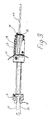
- Figure 3 is a side, partial cross-sectional view of two elements of the tool of the invention, shown with a cable mounted therein in condition for being finally prepared for ultimate termination with a connector; and
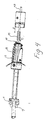
- Figure 4 is a view as in Figure 3 but showing still an additional element of the device of the invention shown in position for final preparation of the cable.
- In Figures 1 and 2 are shown two separate views, in assembled as well as disassembled condition, of the
cable preparation tool 1 in accordance with the invention. More specifically, thecable preparation tool 1 includes a first body or member 3 which has arear portion 5 and afront portion 13. The rear portion consists of a split section having a longitudinal passage 9 therethrough which split portion can have thevarious parts 7 thereof compressible together by a slidable clamp member 11. To facilitate holding of the rear body 3 by the user of the tool, agrip region 17 of conventional construction as will be readily apparent to those of ordinary skill in the art is provided. The front portion of the rear body 3 includes a frusto-conicalouter surface 13 terminating at anend 15 at which the longitudinal opening 9 opens to the exterior. A second, front body ormember 19 is also provided having apassage 25 therethrough which corresponds is size and shape to the frusto-conicalshaped front portion 13. Thisfront body 19 includes agripping region 27 as well as a forward extension 21 constructed for receiving an O-ring 23 thereon. Thefront body 19 is receivable over thefront surface 13 in a manner such as to clamp strength members of a fiber optic cable between the inner walls of thepassage 25 and the outer surface of the frusto-conical front portion 13. - A third body or
member 29, in this case apress body member 29 includes alongitudinal passage 33 extending therethrough which is of a size sufficient to permit a buffer covered fiber to extend through thebody 29 and out an opening at thefront face 31 thereof. Arecess 35 is of sufficient size to fit over the front end 21 ofbody 19 and is held thereon by means of O-ring 23. The length A of body ormember 29 is such that it corresponds to a predetermined size section of fiber which is to be left covered with the buffer layer in a connector and all fiber extending beyond thefront end 31 ofsaid body 29 is to be stripped of the buffer layer for later termination within a fiber optic connector. - In use as shown in Figures 3 and 4, a fiber
optic cable 37 having anouter sheath 39 is inserted from the rear into the rear body 3. The clamp member 11 is slid rearwardly to cause theindividual split portions 7 to clamp thecable 37 therein. The front of the cable extends beyond thefront end 15 of the rear body and theouter sheath 39 is cut at the veryfront end 15 of said front body with thestrength members 41 of a cable extending therefrom. As shown clearly in Figure 3, thesestrength members 41 are folded rearwardly over the frusto-conical surface 13 and thefront body 19 is slid thereover to clamp saidstrength members 41 onto said frusto-conical surface 13. As can be seen from Figure 3, the buffer covered fiber extends from the front. As further shown in Figure 4, aninner sleeve 45 is then received over the buffer coveredfiber 43 and moved in the direction C by means of thepress body 29 which is moved in the direction B which is coincident with the direction C. Thispress body 29 serves to force thesleeve 45 into the region between thestrength members 41 and thebuffer cover fiber 43. As is clearly evident from Figure 4, thisfront press body 29 is received on the front end ofbody 19 and held thereon so that from thefront end 31 of the press body, the buffer can be stripped from the buffer coveredfiber 43. - Thereafter, the
front body 29 is removed and thestrength fibers 41 are cut atsaid front end 15 of the rear body and the entire assembly is then disassembled and the cable has thus been prepared for termination, for example, with the connector of said copending application previously referenced. - Although specific materials for the device have not been elaborated on, preferably this tool is made of a metal, for example, stainless steel or other conventional material well known to those of ordinary skill in the art.
- It is of course to be understood that the embodiment of the present invention herein above discussed is merely illustrative of an even wider variety of embodiments useful in practicing the invention. In all cases the scope of the invention is to be interpreted as defined by the appended claims.
Claims (7)
an elongate first member having a longitudinal passage extending therethrough, said member having one end of clampable construction and another end whose exterior surface is of frusto-conical shape, and further comprising clamp means for clamping said one end onto a fiber optical cable to be received within said longitudinal passage and held by said first member;
second clamp member having a longitudinal passage therethrough of a size such that said second clamp member can be received on the exterior of said other end of said first member in a manner for holding strength members of a fiber optic cable securely against the outer surface of said other end; and
sleeve press means having a longitudinal passage extending therethrough of a size sufficient to permit a buffer covered fiber of a fiber optic cable to pass therethrough, and a recess at one end of predetermined depth for receiving an inner crimp sleeve, which is mountable surrounding said buffer covered optical fiber, in a abutment against the one end of said sleeve press means a manner such that said inner crimp sleeve can be forced into said cable between said strength layer and said buffer layer to provide a support to an outer crimp sleeve of a connector with which the fiber optical cable is to be terminated.
Applications Claiming Priority (2)
| Application Number | Priority Date | Filing Date | Title |
|---|---|---|---|
| US06/892,986 US4715251A (en) | 1986-08-04 | 1986-08-04 | Fiber optic cable preparation tool and method of preparing fiber optic cable for termination with a fiber optic connector |
| US892986 | 1986-08-04 |
Publications (2)
| Publication Number | Publication Date |
|---|---|
| EP0256710A2 true EP0256710A2 (en) | 1988-02-24 |
| EP0256710A3 EP0256710A3 (en) | 1988-07-06 |
Family
ID=25400836
Family Applications (1)
| Application Number | Title | Priority Date | Filing Date |
|---|---|---|---|
| EP87306712A Withdrawn EP0256710A3 (en) | 1986-08-04 | 1987-07-29 | Fiber optic cable preparation tool and method of preparing fiber optic cable for termination with a fiber optic connector |
Country Status (4)
| Country | Link |
|---|---|
| US (1) | US4715251A (en) |
| EP (1) | EP0256710A3 (en) |
| JP (1) | JPS63106611A (en) |
| AU (1) | AU7639787A (en) |
Cited By (3)
| Publication number | Priority date | Publication date | Assignee | Title |
|---|---|---|---|---|
| WO2005047947A1 (en) * | 2003-11-06 | 2005-05-26 | 3M Innovative Properties Company | Anchor for fiber optic cable |
| US6939056B2 (en) | 2003-11-06 | 2005-09-06 | 3M Innovative Properties Company | Anchor for fiber optic cable |
| US7093984B2 (en) | 2003-11-06 | 2006-08-22 | 3M Innovative Properties Company | Anchor for fiber optic cable |
Families Citing this family (9)
| Publication number | Priority date | Publication date | Assignee | Title |
|---|---|---|---|---|
| IT1217347B (en) * | 1988-03-21 | 1990-03-22 | Face Standard Ind | Optical cable joint |
| US5274903A (en) * | 1991-11-08 | 1994-01-04 | Molex Incorporated | Crimping tool system for optical fiber cables |
| CH683655A5 (en) * | 1991-11-12 | 1994-04-15 | Jiri Stepan | Method and device for severing a cable jacket of fibers. |
| US5896787A (en) * | 1996-02-05 | 1999-04-27 | Lucent Technologies, Inc. | Optical fiber stripper |
| US6766096B1 (en) * | 2002-12-31 | 2004-07-20 | Lance P. Thomas | Kit for converting optical fiber retaining clip |
| WO2010098844A2 (en) | 2009-02-24 | 2010-09-02 | Adc Telecommunications, Inc. | Fiber optic cable pass-thru fitting |
| US9116310B2 (en) | 2009-03-06 | 2015-08-25 | Adc Telecommunications, Inc. | Fiber optic cable pass-thru fitting with a cable retention member for routing strength members |
| WO2010117656A2 (en) * | 2009-04-06 | 2010-10-14 | Adc Telecommunications, Inc. | Drop cable pass-thru fitting |
| US8677861B2 (en) | 2011-03-31 | 2014-03-25 | Corning Cable Systems Llc | Bladeless stripping device |
Citations (2)
| Publication number | Priority date | Publication date | Assignee | Title |
|---|---|---|---|---|
| GB2144070A (en) * | 1983-06-28 | 1985-02-27 | Wesley Durham Nicholls | Optical fibre cable preparation tool |
| US4576437A (en) * | 1981-03-06 | 1986-03-18 | Allied Corporation | Connector for fibre optic cable |
Family Cites Families (3)
| Publication number | Priority date | Publication date | Assignee | Title |
|---|---|---|---|---|
| FR2448238A1 (en) * | 1979-01-31 | 1980-08-29 | Radiall Sa | PROCESS FOR PREPARING THE END OF A VERY HIGH FREQUENCY FLEXIBLE COAXIAL CABLE FOR THE PLACEMENT OF A CONNECTOR ELEMENT |
| US4459746A (en) * | 1982-03-03 | 1984-07-17 | Optelecom, Incorporated | Tool for cleaning the exposed end of an optical fiber |
| DE3406915A1 (en) * | 1984-02-25 | 1985-09-05 | Philips Patentverwaltung Gmbh, 2000 Hamburg | Method and device for stripping off the coating of glass fibres |
-
1986
- 1986-08-04 US US06/892,986 patent/US4715251A/en not_active Expired - Fee Related
-
1987
- 1987-07-29 EP EP87306712A patent/EP0256710A3/en not_active Withdrawn
- 1987-08-03 JP JP62192745A patent/JPS63106611A/en active Pending
- 1987-08-03 AU AU76397/87A patent/AU7639787A/en not_active Abandoned
Patent Citations (2)
| Publication number | Priority date | Publication date | Assignee | Title |
|---|---|---|---|---|
| US4576437A (en) * | 1981-03-06 | 1986-03-18 | Allied Corporation | Connector for fibre optic cable |
| GB2144070A (en) * | 1983-06-28 | 1985-02-27 | Wesley Durham Nicholls | Optical fibre cable preparation tool |
Cited By (4)
| Publication number | Priority date | Publication date | Assignee | Title |
|---|---|---|---|---|
| WO2005047947A1 (en) * | 2003-11-06 | 2005-05-26 | 3M Innovative Properties Company | Anchor for fiber optic cable |
| US6939056B2 (en) | 2003-11-06 | 2005-09-06 | 3M Innovative Properties Company | Anchor for fiber optic cable |
| US6953287B2 (en) | 2003-11-06 | 2005-10-11 | 3M Innovative Properties Company | Anchor for fiber optic cable |
| US7093984B2 (en) | 2003-11-06 | 2006-08-22 | 3M Innovative Properties Company | Anchor for fiber optic cable |
Also Published As
| Publication number | Publication date |
|---|---|
| EP0256710A3 (en) | 1988-07-06 |
| JPS63106611A (en) | 1988-05-11 |
| US4715251A (en) | 1987-12-29 |
| AU7639787A (en) | 1988-02-11 |
Similar Documents
| Publication | Publication Date | Title |
|---|---|---|
| US4447120A (en) | Fiber optic cable clamp | |
| CA1201314A (en) | Connector for fiber optic member | |
| US4648688A (en) | Connector for fiber optic member including polishing fixture and method of terminating same | |
| US5559917A (en) | Connector for terminated fiber optic cable | |
| US4715251A (en) | Fiber optic cable preparation tool and method of preparing fiber optic cable for termination with a fiber optic connector | |
| US4773725A (en) | Termination of a fiber optic transmission member and method therefore | |
| DE60125292T2 (en) | A field mountable fiber optic ribbon cable connector and installation tool | |
| US5140662A (en) | Method of assembling connector and cable | |
| EP0664467A1 (en) | Force transfer system for an optical fiber connector | |
| EP0563995A1 (en) | Optical fiber connector | |
| EP0484996A1 (en) | Optical fibre connector | |
| EP0462845A2 (en) | Optical connector and a method for assembling the same | |
| EP0131283A2 (en) | Method and apparatus for anchoring optical cables to optical connectors | |
| CA1177234A (en) | Device for positioning optical fibers in a terminal connector for splicing two optical-fiber transmission cables | |
| EP1148364A3 (en) | Strain relief clamping mechanism for an optical fiber connector | |
| EP0061243B1 (en) | Optical waveguide connector | |
| JP2005114860A (en) | Ferrule for optical connector and method for assembling optical connector | |
| NZ207072A (en) | Cleaving fiber optic cable core flush with mating end of connector | |
| EP0720752B1 (en) | Fiber optic connector with strain relief means | |
| JP2003529094A (en) | Adapter holding method and pull protector for optical fiber cable | |
| EP0467156B1 (en) | Strain relief connector for optical fiber | |
| EP0481339B1 (en) | Tool to facilitate loading an optical fiber in a connector component | |
| EP0095281A2 (en) | Connector for fiber optic member | |
| EP0608627B1 (en) | Method of forming an optical fibre connector | |
| US4639068A (en) | Holder for coupling assembly |
Legal Events
| Date | Code | Title | Description |
|---|---|---|---|
| PUAI | Public reference made under article 153(3) epc to a published international application that has entered the european phase |
Free format text: ORIGINAL CODE: 0009012 |
|
| AK | Designated contracting states |
Kind code of ref document: A2 Designated state(s): DE FR GB IT SE |
|
| PUAL | Search report despatched |
Free format text: ORIGINAL CODE: 0009013 |
|
| AK | Designated contracting states |
Kind code of ref document: A3 Designated state(s): DE FR GB IT SE |
|
| STAA | Information on the status of an ep patent application or granted ep patent |
Free format text: STATUS: THE APPLICATION IS DEEMED TO BE WITHDRAWN |
|
| 18D | Application deemed to be withdrawn |
Effective date: 19890109 |
|
| RIN1 | Information on inventor provided before grant (corrected) |
Inventor name: MARGOLIN, MARK Inventor name: GROIS, IGOR Inventor name: MOORE, JAMES ELTON |