EP0272969A1 - Method and programmable apparatus for transcribing strings of characters - Google Patents
Method and programmable apparatus for transcribing strings of characters Download PDFInfo
- Publication number
- EP0272969A1 EP0272969A1 EP87402737A EP87402737A EP0272969A1 EP 0272969 A1 EP0272969 A1 EP 0272969A1 EP 87402737 A EP87402737 A EP 87402737A EP 87402737 A EP87402737 A EP 87402737A EP 0272969 A1 EP0272969 A1 EP 0272969A1
- Authority
- EP
- European Patent Office
- Prior art keywords
- transcoding
- message
- incoming
- transcoded
- word
- Prior art date
- Legal status (The legal status is an assumption and is not a legal conclusion. Google has not performed a legal analysis and makes no representation as to the accuracy of the status listed.)
- Granted
Links
Images

Classifications
-
- H—ELECTRICITY
- H03—ELECTRONIC CIRCUITRY
- H03M—CODING; DECODING; CODE CONVERSION IN GENERAL
- H03M7/00—Conversion of a code where information is represented by a given sequence or number of digits to a code where the same, similar or subset of information is represented by a different sequence or number of digits
Definitions
- the present invention relates, in general, to problems of incompatibility of character encoding and of instruction messages which may arise between two different data processing systems when these must communicate with each other.
- one of the systems is a microcomputer or a terminal knowing a given alphabet of characters and a message structure
- the other system is a central electronic system knowing different alphabets and message structure.
- Equipment which must be by nature compatible and adaptable is very often, in fact, incompatible, such as terminals equipped for the most part with a keyboard having keys determining program functions to which are assigned coding combinations arbitrarily fixed by the manufacturer. .
- Some terminals use specific order codes, respectively for their internal management and for the management of peripherals connected to them.
- Such terminals connected to a central electronic system which do not know the same order codes exhibit incomplete operation.
- the constant evolution of computer techniques contributes to the appearance of different types of terminals, in particular color display terminals, making the problems of incompatibility more delicate.
- the existing standardization provides standardized exchange protocols, such as ANSI, VT52, VT100, or the videotex standard. These protocols have the advantage of making the materials adaptable for certain types of exchanges but Often reduce the field of use of more efficient equipment.
- the present invention aims to provide a method and apparatuses for transcoding to solve the incompatibility problems mentioned above.
- a message to be transcoded transmitted by a first digital data processing system to a second digital data processing system can be composed of one or more binary words representing respectively, in a first alphabet associated with said first system, a character or a character string to which a specific entity or a specific meaning generally correspond.
- the transmitted message to be transcoded may have no equivalent or meaning for the second system, in which case no message will be delivered to the second system.
- the transmitted message to be transcoded may correspond to one or more binary words representing respectively in a second alphabet associated with the second system, a character or a character string.
- a transcoding apparatus for implementing the method according to the invention is as defined in claim 4.
- the invention also aims to provide programmable transcoding devices so that the same device is adaptable and usable for solving different types of coding incompatibility.
- a programmable transcoding device comprises means for initializing processing means during a phase prior to transcoding, by loading said RAM processing means into a random access memory.
- transcoding tables and other tables including one or more transcoded message tables.
- the method according to the invention has the following main advantages: - it is not necessary that the character strings to be transcoded include "delimiting characters" signaling the beginning and the end of the string. - the transcoding processing time is negligible. Indeed, due to the use of transcoding tables containing precalculated values, the transcoding operations are simple and boil down to offsets, comparisons, and reads and writes in the tables.
- a unidirectional transcoding to be carried out between a first digital data processing system S1 transmitting messages and a second digital data processing system S2 waiting for these messages.
- a person skilled in the art can produce a bidirectional transcoding device, by doubling transcoding tables and ensuring time-sharing processing for the two directions of transmission and the overall flow control of the device.
- the first and second systems S1 and S2 respectively use first and second alphabets composed of characters which are for the most part editable and of commands to which correspond binary words having a number of bits B determined, all the possible binary combinations of B bits can be used by the first and second alphabets.
- the commands are, for example, utility commands such as "buzzer action”, “carriage return”, and “line feed” noted respectively “BEL”, "CR”, and "LF” in most standard alphabets existing. Subsequently in the description the term character is used, as is customary, either for an editable character or for an order.
- the system S1 transmits incoming messages ME to the programmable transcoding device AT via a unidirectional data transmission link 111.
- An incoming message consists of a single incoming word (CE) or of a sequence of N incoming binary words [(CE1), (CE2), ... (CE n ), ... (CE N )], N being a variable integer which can vary from 1 to a predetermined maximum integer Nmax and representing the length of the incoming message.
- Each of the incoming words of a series of words corresponds to a rank n, n being an integer between 1 and N, representative of its chronological order of arrival in the transcoding apparatus AT with respect to the first recognized word (CE1) of the incoming suite.
- the incoming words (CE) and (CE1), (CE2), ... (CE n ), ... (CE N ) correspond in the system alphabet S1 of the characters CE and CE1, CE2, ... CE n , ... CE N respectively.
- Each incoming word is received in the transcoding device AT by an input interface 1 via the transmission link 111.
- a dialogue link 111a is provided between the system S1 and the interface 1 so that the latter can invite the S1 system, if necessary, to suspend the transmission.
- This dialogue link 111a can be suppressed by the use of control characters, which can be characters, "XON” and "XOFF", to authorize and suspend the transmission respectively.
- the control characters, "XON” and "XOFF” are then transmitted to the system S1 via the transmission link 111, which in this case is bidirectional.
- the interface 1 comprises an input adapter 11 and a queue 12.
- the input adapter 11 serves to adapt the data transmission link 111, which can be of the serial or parallel type, to internal buses of the AT transcoding device.
- the adapter 111 can be a specialized circuit for this type of transmission, such as a UART (Universal Asynchronous Receiver Transmitter), or more simply a serial register.
- UART Universal Asynchronous Receiver Transmitter
- - parallel in the case of a parallel transmission link 111, input buffer memories, called “buffers”, may be suitable.
- the queue 12 receives the incoming words delivered by the adapter 11 in parallel format through a bus 112.
- the queue 12 is a storage register of FIFO (First in, First out) type.
- the adapter 11 For each incoming word (CE) received, the adapter 11 delivers a word detection signal to a unit via a link 32. exchange management 3. The incoming word (CE) is then presented as an output on the bus 112 connected to the entry to the queue 12. The management unit 3 being notified of the arrival of a word through the link 32, a storage control signal is applied to the queue 12, by a link 33, to memorize in the queue 12 the incoming word (CE) present in the bus 112.
- Processing and control means are included in the transcoding apparatus AT in the form of a central unit 4.
- the unit 4 contains a read-only memory 42 of the PROM type containing micro-instructions for executing a transcoding algorithm and to control the exchange management unit 3.
- the central unit 4 delivers control words to the management unit 3 via a control bus 41.
- the central unit 4 is constantly informed of the state of the transcoding device by a status word delivered by the exchange management unit 3 in a status bus 36.
- the central unit 4 is ready to read an incoming word (CE) stored in the queue wait 12, in order to carry out transcoding processing, it transmits to the exchange management unit 3 a control word by the control bus 41.
- CE incoming word
- the management unit 3 decodes this control word, generates a signal by the link 33 to signify to the queue 12 to present on an output bus 122 connected to an input 51 a referral device 5, the first incoming word (CE) in chronological order of arrival.
- the word (CE) being present on the bus 122, the management unit then supplies the signaling device 5 with a signal via a link 35, to control the connection of the input 51 to an input / output 52 of the switching device 5.
- the input / output 52 is connected to the central unit 4 by a data bus 521.
- the central unit 4 reads the incoming word (CE) presented on the bus 521.
- the incoming word (CE) is identified in the central unit 4 using transcoding tables contained in a random access memory 43 of the RAM type.
- the incoming word (CE) can be identified as having no corresponding transcoded outgoing message, in which case it is not taken into account.
- the central unit 4 then controls the reading of the next incoming word in the queue 12 in the manner which comes to be described, by transmitting a command word to the exchange management unit 3 via the bus 41.
- the incoming word (CE) can be identified as the first word (CE1) of a series of N incoming words known by the central unit 4.
- the central unit 4 then reads and identifies the following words of the incoming sequence.
- the incoming word (CE) or following N incoming words [(CE1), (CE2), ... (CE n ), ... (CE N )] constituting an incoming message ME can correspond to an outgoing transcoded message MS composed of an outgoing word (CS) or of a sequence of M outgoing transcoded words [(CS1), (CS2), ... (CS m ), ... (CS M )] where m is an integer understood between 1 and M, and M is a variable integer, generally different from the integer N, which can vary from 0 to a predetermined maximum number Mmax and representing the length of the outgoing message MS.
- the central unit 4 supplies the exchange management unit 3 with another word control by the bus 41 in order to control the routing of each of the outgoing words of the message MS to an output interface 2 transmitting transcoded outgoing words (CS), via a transmission link 211, to the second system S2.
- the management unit 3 On receipt of the command word, the management unit 3 causes the input / output 52 of the switching device 5 to be connected with an output 53 of the same device 5, by activating the control link 35.
- the output 53 is connected by a bus 222 to the input of a queue 22, similar to the queue 12, included in the output interface 2.
- Each of the transferred outgoing words is stored, in response to a control signal delivered by the management unit 3 via a control link 38, in the queue 22, with transcoded outgoing words to be transmitted to the system S2.
- the output interface 2 comprises, in addition to the queue 22, an output adapter 21 connected as an output to the second system S2 by the transmission link 211 and a dialog link 211a.
- the link 211a can, similarly, as the dialogue link 111a, be suppressed by the use of the already mentioned command characters "XON" and "XOFF".
- the function of adapter 21 is, as is the input adapter 11, to adapt the internal buses of the transcoding device to the unidirectional transmission link 211, which can be, like the link 111, of the serial or parallel type.
- a link bus 221 provides transcoded outgoing words from the queue 22 at the input of the adapter 21.
- the adapter 21 When the adapter 21 is ready to transmit an outgoing word (CS) stored in the queue 22, it signals this to the exchange management unit 3 via a link 39.
- the management unit 3 then orders, via the link 38, the queue 22 to present an outgoing word as an output on the bus 221 (CS).
- the outgoing word (CS) is read by the adapter 21 which transmits it via the link 211 to the system S2.
- the exchange management unit 3 performs the management and control of the signals exchanged between the different circuits of the transcoding apparatus as well as between the transcoding apparatus and the systems S1 and S2.
- the management unit 3 receives from the central unit 4 a control word relating to the exchanges of data inside the transcoding apparatus from which various control signals are sent sent to the interfaces 1 and 2 by the links. 31, 33, 38, and 40, as well as to the switching device 5 by the link 35.
- a status word is provided by the exchange management unit 3 to the central unit 4, through the bus 36 to inform it of any change in communication with the S1 or S2 system.
- the exchange management unit 3 are provided in a known manner, two write and read counters and a comparator associated with each of the two queues in order to determine the respective filling level of each of the queues. and to compare said levels with high and low filling thresholds defined so as to regulate the bit rates, on the one hand between the system S1 and the transcoding device AT and on the other hand between the transcoding device AT and the S2 system, which in general are different.
- the high and low thresholds make it possible, for each queue, to manage a flow control according to a hysteresis cycle intended to avoid a deterioration of the performance of the device during oscillation around a threshold single filling. So when a queue, 12 or 22, reaches a filling level at least equal to the high threshold, a detection is made by the associated comparator and the exchange management unit 3 suspends the filling of the queue concerned by stopping the transmission and the writing of words in the file. The exchange management unit 3 again authorizes the writing of words in the queue, when the filling level of the queue becomes less than or equal to the low threshold.
- a filling indicator for a queue can take two states, a "filling suspension” state and a "normal operation” state. An indicator comes to the "filling suspension” state when the exchange management unit 3 detects a filling level equal to or greater than the high threshold for the corresponding queue. An indicator comes to the "normal operation” state when the exchange management unit 3 detects a filling level equal to or less than the low threshold of the corresponding queue.
- Exceeding the high threshold in the queue 22 causes the transmission of a status word intended for the central unit 4, via the status bus 36.
- the unit 4 then suspends writing of outgoing words in the queue 22 and any request to read, via the bus 41, the word contained in the queue 12.
- a high threshold exceeded in the queue 12 results in activation of the link 111a to the S1 system so as to stop the transmission of incoming words.
- the exchange management unit 3 is connected to the adapter 11, by the control link 31.
- a filling level of the queue 22 less than or equal to the low threshold causes, if the filling indicator associated with the queue 22 was set to the "filling suspension" state, the transmission of a status word intended for the central unit 4, via the status bus 36. The unit 4 then resumes the writing of outgoing words in the queue 22 and the requests to read the queue waiting 12.
- a filling level of the queue 12 lower than or equal to the low threshold causes, if the filling indicator associated with the queue 12 was set to the state "suspension of filling", the transmission of a command on the link 31 intended to deactivate the link 111a.
- the link 211a between the system S2 and the adapter 21 is provided so that the system S2 requests to suspend, that is to say to stop or delay, a transmission of outgoing words, for example, following d 'a failure or a filling of buffers in the S2 system.
- the request for suspension is transmitted by the adapter 21 to the exchange management unit 3, which validates it by delivering to the adapter 21, via the link 40, a command to stop transmission to the system S2.
- the transcoding device continues to operate with the system S1 until a possible stop caused by an overshoot of the high threshold in the queue 12.
- the adapter 21 informs the unit 3, which takes this new state into account and delivers to the adapter 21, via the link 40, an authorization to transmit to the system S2 .
- the transcoding tables are downloaded into random access memory 43 in the central unit 4 during a preliminary initialization phase, prior to the putting into operation of the transcoding device.
- a connection 61 is provided between the central unit 4 and a microcomputer 6 having served for the preparation of the tables on the basis of an analysis of the alphabets of characters of the systems S1 and S2, of the various possibilities of communication between system S1 and system S2, as well as possible conflicts that may arise between the two systems.
- the microcomputer can also be used for viewing data transmitted by the central unit 4 during the transcoding operations, likely to interest an operator.
- the central unit 4 proceeds to address the different transcoding tables, according to addressing modes known as relative addressing mode and indexed addressing mode.
- the relative addressing mode consists in supplying to a processor, an address word representing an offset to be generally carried out with respect to the value of a program counter in order to obtain an effective address in a memory area.
- the address word is supplied to the processor with the address of a so-called index register containing a value to be added to the address word to obtain an effective address.
- the index is located in RAM and can be modified during the program, which allows great flexibility of addressing.
- Relative and indexed addressing modes are in frequent use for addressing tables, because they simply make it possible to convert data into an address in a table that can be installed in any memory area.
- the transcoding tables include input tables TE1 to TE Nmax , a message table TM, an ITE index table for addressing the input tables, and an ITM index table for addressing the message table.
- the TE1 to TE Nmax input tables support a logical tree structure for identifying incoming messages. This tree structure includes different tracking possibilities leading to the identification of isolated incoming words or a series of incoming words known by the transcoding device.
- Each of the input tables TE1, TE2, ... TE n , ... TE N , ... TE Nmax is located in random access memory by a table start address (TE1), (TE2), ... (TE n ), ... (TE N ), ... (TE Nmax ) respectively.
- the transcoding in succession of N incoming words uses the input tables TE1 to TE N.
- the incoming words (CE1), (CE2), ... (CE n ), ... (CE N ) address in the TE1 input tables, TE2, ... TE n , ... TE N , with respect to the start addresses (TE1), (TE2), ... (TE n ), ... (TE N ), transcoding words Mt1, Mt2, ... Mt n , ... Mt N respectively.
- the input tables TE2 to TE Nmax are only used for transcoding incoming messages to which more than one outgoing word can correspond, their function being different from that of the input table TE1 they can also be called "tables of referral ".
- Each of the input tables comprises as many transcoding words as different incoming words that can be delivered by the system S1, that is 2 B-1 transcoding words, assuming that each incoming word comprises B bits, typically 8 bits divided into two half-bytes in hexadecimal digital base.
- An incoming word having the value noted “00 H " in hexadecimal numerical base corresponds to a character, noted "NULL" in most standard alphabets.
- the character NHL although it can be treated like any other character, is used in the input tables, or reference tables, TE2 to TE Nmax to take into account incoming messages of greater length.
- Each of the transcoding words Mt n comprises B + 1 bits and is divided into first and second fields ch1 and ch2.
- the first field ch1 is an identification indicator; it is made up of the most significant bit, known as the most significant bit MSB.
- the second field ch2 is composed of the remaining B bits of the transcoding word Mt n .
- the field ch2 is generally an address used by the central unit to continue the transcoding processing; it can also, in the entry table TE1, be an outgoing transcoded word (CS).
- the message table TM is located in RAM by a table start address (TM). Transcoded outgoing messages made up of outgoing words each having B bits are stored in the table TM. A transcoded outgoing message MS is preceded in the table TM by the number M of outgoing words contained in this message.
- the number M and the outgoing words (CS1), (CS2), ... (CS m ), ... (CS M ) of a message MS are respectively stored at addresses AM and AM + 1, AM + 2 , ... AM + m, ... AM + M relative to the address (TM).
- the ITE index table is an intermediate table used by the central unit to address a transcoding word Mt n in an input table TE n ; it contains the table start addresses (TE1) to (TE Nmax ) of the input tables TE1 to TE Nmax .
- the ITE table is stored in memory at a start address (ITE).
- Each of the table start addresses (TE1) to (TE Nmax ) is located in the ITE index table by an address, A1 to A Nmax respectively.
- the ITM index table is an intermediate table used by the central unit to address outgoing transcoded messages MS 'in the message table (TM) from transcoding words Mt' from the input table TE1.
- the ITM table is located in RAM by the start address (ITM).
- Fig. 2 shows the use of the transcoding tables by the central unit for three typical cases of transcoding processing.
- an incoming message consisting of a single incoming word (CE) corresponds to a transcoded message composed of a single outgoing transcoded word (CS).
- the incoming word (CE) addresses in the table TE1, with respect to the table start address (TE1), a transcoding word Mt.
- the field ch1 of the word Mt in the binary state "0" indicates to the central unit that the second field ch2 of the word Mt is the outgoing transcoded word (CS).
- an incoming message consisting of a single incoming word (CE ') corresponds to an outgoing transcoded message MS' of length M 'different from 1.
- the fields ch1 and ch2 of a transcoding word Mt' selected by the word (CE ') are then respectively in the binary state "1", unlike the previous case CAS1, and equal to the incoming word (CE').
- the central unit uses the word (CE ') to address an address word AM' in the index table ITM.
- the word AM 'read by the central unit is, in the message table TM, the address of the message MS 'corresponding to the word (CE').
- an incoming message consisting of a series of N incoming words [(CE1), (CE2), ... (CE n ), ... (CE N )] corresponds to an outgoing transcoded message MS comprising a sequence of M outgoing words [(CS1), (CS2), ... (CS m ), ... (CS M )].
- the first incoming word (CE1) selects in the input table TE1 a transcoding word Mt1 having a first field ch1 in the binary state "1".
- the second field ch2 of the word Mt1 is different from the incoming word (CE1), unlike the previous case CAS 2, which allows the central unit to recognize the word (CE1) as being the first word in a known word sequence .
- the field ch2 of the word Mt1 is equal to the address A2 locating the start address (TE2) in the ITE index table.
- a second incoming word (CE2) selects from the table TE2, relative to the start address (TE2) read from the index table ITE, a second transcoding word Mt2 having a first field ch1 in binary state "1 ".
- the field ch1 of the word Mt2 in the binary state "1" confirms the identification path followed and indicates to the central unit that a third incoming word (CE3) is expected.
- the field ch2 of the word Mt2 is the address A3 located in the ITE table, the start address (TE3) of the input table TE3.
- the incoming word (CE3) is used analogously to the word (CE2) to select from the TE3 input table a transcoding word Mt3 whose field ch1 in binary state "1" indicates to the central unit to continue the same process, up to the incoming word (CE N ).
- the incoming word (CE N ) selects in the table TE N a transcoding word Mt N whose field ch1 in binary state "0" allows the central unit to recognize the word (CE N ) as being the last word subsequently known.
- the field ch2 then equal to an address AM of the message table TM is read by the central unit in order to address in the table TM the outgoing transcoded message MS corresponding.
- the number M of words of the message MS stored at the address AM is between 0 and Mmax. For a corresponding MS message, having a single word, the number M is equal to 1.
- a single outgoing word (CS1) is thus read, at the address AM + 1.
- the case CAS3 which has just been described relates to a path in the input tables TE1 to TE Nmax leading directly to the identification of a series of incoming words as being an incoming message to be transcoded known by the central unit.
- an incoming word (CE n ) identified as the n th incoming word of a known sequence of words
- an incoming word (CE n + 1 ) may occur which is not the (n + 1) th expected word from the known sequence of incoming words.
- the incoming word (CE n + 1 ) addresses in the input table TE n + 1 a transcoding word Mt n + 1 having a determined value, for example "00 H ".
- the value "00 H " thus determined is for the central unit a failure code indicating to it, taking into account the last incoming word (CE n + 1 ), either a failure in the transcoding or the existence of a known message longer in length.
- the central unit then initializes the transcoding words Mt1 to Mt n + 1 with new values contained in a table associated with the input tables.
- a new transcoding test is undertaken from the incoming words (CE1) to (CE n + 1 ) previously saved in an incoming word table.
- the table associated with the input tables contains the different possible transcoding words at the same address in an input table; these different words correspond to different possibilities of pathways. Different tracking possibilities can be tried by the central unit before transcoding the words (CE1) to (CE p ), where p is an integer greater than or equal to 1, by one or more transcoded outgoing messages.
- transcoding tables are possible so as to adapt a transcoding to be carried out to addressing possibilities of the central unit necessarily limited and to allow great flexibility in the choice of the values assigned to address words, with respect to the different possible values of the incoming words.
- the size of the input tables TE2 to TE Nmax described above can be significantly reduced by the use of index tables.
- an incoming word (CE p ) addressing an input table TE p where p is an integer between 2 and Nmax, and successfully identified, that is to say identified as being the p th word entering the expected word sequence, is generally between a minimum incoming word (CE p ) minimum and a maximum incoming word (CE p ) maximum leading to success in the identification by the table TE p .
- An ITE p index table associated with the TE p table containing the words (CE p ) mini and (CE p ) max and used for addressing the TE p table makes it possible to limit the size of the input table TE p the number of words between (CE p ) minimum and (CE p ) max .
- the position of the ITE p index table associated with the TE p table is preferably contiguous to the TE p table and precedes the latter in the RAM memory area of the device.
- the words (CE p ) mini and (CE p ) max are thus addressed by making an offset of -2 and -1 respectively with respect to the table start address (TE p ) of the TE p table.
- An incoming word (CE p ) read by the central unit is first compared to the words (CE p ) minimum and (CE p ) maximum . If the incoming word (CE p ) is not included in the range defined by the words (CE p ) minimum and (CE p ) maximum , the central unit directly deduces a failure of the transcoding test in progress.
- the corresponding transcoding word MT p is addressed in the input table TE p from the address of start (TE p ) with the word (CE p ) - (CE p ) mini representing the numerical difference between the words (CE p ) and (CE p ) mini .
- the message table TM can be replaced by Nmax message tables TM1 to TM Nmax respectively associated with the input tables TE1 to TE Nmax .
- an input table TE q where q is an integer between 1 and Nmax, address in the message table TM q associated with it, an outgoing message MS "using respective index tables, IM1 q and IM2 q .
- the IM1 q index table is located by its start address (IM1 q ) and is made up of 3 B-bit words, Mt qmini , Mt qmaxi , and L q .
- the index table IM2 q includes L q words of B bits. Each of the words in the index table IM2 q is an address of an outgoing message in the corresponding message table TM q , relative to a start address (TM q ) of the message table.
- a TM q message table is located by the table start address (TM q ).
- An outgoing message MS "from the message table is addressed in the message table TM q by an address word AM" stored in the index table IM2 q .
- the central unit after checking that the word Mt q is understood between the words Mt qmini and Mt qmaxi , read the address word AM "in the index table IM2 q by addressing it from the start address (IM2 q ) by the numerical difference of the words Mt q and Mt qmini , let Mt q -Mt qmini .
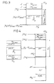
- the tables IM1 q , IM2 q , and TM q are contics in the RAM memory area of the device, as shown in Fig.4.
- the central unit can then deduce the addresses of the start of tables (IM2 q ) and (TM q ) from the address (IM1 q ), from the invariable size of the table IM1 q fixed at 3 words, and of the word L q representing the size of the table IM2 q , and thereby reduces the number of read operations necessary for the addressing of outgoing messages.
- the transcoding device can undergo various modifications to adapt it to different operating modes or to minimize its cost.
- the exchange management unit 3 in the embodiment which has just been described, can be carried out in wired logic using decoders, flip-flops and logic gates, or included in the central unit ensuring exchange management from a firmware contained in read-only memory.
- the exchange management unit in a more sophisticated embodiment, in particular for a bidirectional transcoding apparatus, can be implemented using a microprocessor microcontroller, slave of the central unit and managing communications autonomously.
- the central unit can contain, in read-only memory, software for generating transcoding tables.
- the microcomputer 6 can then be replaced by a simple dialogue terminal, or a hexadecimal keyboard provided with displays, to introduce into the transcoding apparatus various parameters and data to be entered relating to the systems S1 and S2 and to the operating mode. longed for.
- the terminal or the microcomputer 6 may be connected to the transcoding device only during the prior initialization phase, the connection of the terminal to the device which can then be carried out via interface 1 or 2.
Abstract
Appareil programmable de transcodage (AT) dans lequel des suites de mots binaires de longueurs variables correspondant à des chaînes de caractères dans un premier alphabet sont transcodés en d'autres suites de mots binaires intelligibles dans un second alphabet. L'appareil est relié à des systèmes numériques (S1, S2) échangeant des suites de mots par des interfaces (1, 2) munies de files d'attente (12, 22). Une unité centrale (4) connectée aux interfaces à travers un dispositif d'aiguillage (5) reçoit les suites entrantes et délivre des suites de mots binaires transcodés/ Une unité de gestion d'échange (3) assure le contrôle des transferts de données dans l'appareil ainsi que la régulation des débits de mots entre l'appareil et les systèmes numériques. Un terminal ou un micro-ordinateur peut également équiper l'appareil pour l'élaboration de tables de transcodage à télécharger dans une mémoire vive (43) de l'unité centrale.Programmable transcoding apparatus (AT) in which strings of binary words of variable lengths corresponding to strings of characters in a first alphabet are transcoded into other strings of intelligible binary words in a second alphabet. The device is connected to digital systems (S1, S2) exchanging word sequences by interfaces (1, 2) provided with queues (12, 22). A central unit (4) connected to the interfaces through a switching device (5) receives the incoming suites and delivers suites of transcoded binary words / An exchange management unit (3) ensures the control of data transfers in the device as well as the regulation of the word rates between the device and the digital systems. A terminal or a microcomputer can also equip the apparatus for the preparation of transcoding tables to be downloaded into a random access memory (43) of the central unit.
Description
La présente invention concerne, d'une manière générale, des problèmes d'incompatibilité de codage de caractères et de messages d'instruction pouvant se poser entre deux systèmes différents de traitement de données lorsque ceux-ci doivent communiquer entre eux. Par exemple, l'un des systèmes est un micro-ordinateur ou un terminal connaissant un alphabet de caractères et une structure de message donnés, et l'autre système est un système électronique central connaissant des alphabet et structure de message différents.The present invention relates, in general, to problems of incompatibility of character encoding and of instruction messages which may arise between two different data processing systems when these must communicate with each other. For example, one of the systems is a microcomputer or a terminal knowing a given alphabet of characters and a message structure, and the other system is a central electronic system knowing different alphabets and message structure.
Il existe actuellement un large éventail de terminaux, de micro-ordinateurs, et de systèmes électroniques n'utilisant pas toujours le même alphabet de caractères, le même protocole d'échanges en transmission et réception, ou la même structure de message. Cette incompatibilité entre ces différents matériels rend souvent impossible leurs interconnexions pour la réalisation d'équipements ou de systèmes plus évolués.There is currently a wide range of terminals, microcomputers, and electronic systems which do not always use the same alphabet of characters, the same protocol of exchanges in transmission and reception, or the same structure of message. This incompatibility between these different materials often makes their interconnections impossible for the realization of more advanced equipment or systems.
Des matériels devant être par nature compatibles et adaptables sont bien souvent, en fait, incompatibles, tels que les terminaux équipés pour la plupart d'un clavier ayant des touches déterminant des fonctions-programmes auxquelles sont attribuées des combinaisons de codage fixées arbitrairement par le constructeur. Certains terminaux font appel à des codes d'ordres spécifiques, respectivement pour leur gestion interne et une gestion de périphériques qui leurs sont raccordés. De tels terminaux raccordés à un système électronique central ne connaissant pas les mêmes codes d'ordres présentent un fonctionnement incomplet. De plus, l'évolution constante des techniques informatiques contribue à l'apparition de différents types de terminaux, notamment des terminaux à visualisation en couleurs, rendant plus délicat les problèmes d'incompatibilité.Equipment which must be by nature compatible and adaptable is very often, in fact, incompatible, such as terminals equipped for the most part with a keyboard having keys determining program functions to which are assigned coding combinations arbitrarily fixed by the manufacturer. . Some terminals use specific order codes, respectively for their internal management and for the management of peripherals connected to them. Such terminals connected to a central electronic system which do not know the same order codes exhibit incomplete operation. In addition, the constant evolution of computer techniques contributes to the appearance of different types of terminals, in particular color display terminals, making the problems of incompatibility more delicate.
La normalisation existante permet de disposer de protocoles d'échanges normalisés, tels que l'ANSI, le VT52, le VT100, ou le standard vidéotex. Ces protocoles ont l'avantage de rendre adaptables les matériels pour certains types d'échanges mais réduisent bien souvent le champ d'utilisation de matériels plus performants.The existing standardization provides standardized exchange protocols, such as ANSI, VT52, VT100, or the videotex standard. These protocols have the advantage of making the materials adaptable for certain types of exchanges but Often reduce the field of use of more efficient equipment.
Par ailleurs, la gamme des alphabets normalisés existants est en perpétuelle évolution pour répondre aux différents besoins nationaux et s'adapter aux nouvelles possibilités technologiques. Ainsi à un même caractère peut correspondre des combinaisons binaires de codage différentes suivant l'alphabet normalisé qui est utilisé.In addition, the range of existing standardized alphabets is constantly evolving to meet different national needs and adapt to new technological possibilities. Thus, the same character can correspond to different coding binary combinations according to the standardized alphabet which is used.
La présente invention vise à fournir un procédé et des appareils de transcodage pour résoudre les problèmes d'incompatibilité évoqués ci-dessus.The present invention aims to provide a method and apparatuses for transcoding to solve the incompatibility problems mentioned above.
A cette fin, le procédé selon l'invention est tel que défini dans la revendication 1.To this end, the method according to the invention is as defined in
Selon le procédé de l'invention, un message à transcoder transmis par un premier système numérique de traitement de données vers un second système numérique de traitement de données peut être composé d'un ou plusieurs mots binaires représentant respectivement, dans un premier alphabet associé audit premier système, un caractère ou une chaîne de caractères auxquels correspondent généralement une entité déterminée ou une signification déterminée. Le message à transcoder transmis peut ne pas avoir d'équivalent ou de signification pour le second système, auquel cas aucun message ne sera délivré au second système. Au message à transcoder transmis peut correspondre un ou plusieurs mots binaires représentant respectivement dans un second alphabet associé au second système, un caractère ou une chaîne de caractères.According to the method of the invention, a message to be transcoded transmitted by a first digital data processing system to a second digital data processing system can be composed of one or more binary words representing respectively, in a first alphabet associated with said first system, a character or a character string to which a specific entity or a specific meaning generally correspond. The transmitted message to be transcoded may have no equivalent or meaning for the second system, in which case no message will be delivered to the second system. The transmitted message to be transcoded may correspond to one or more binary words representing respectively in a second alphabet associated with the second system, a character or a character string.
Un appareil de transcodage pour la mise en oeuvre du procédé selon l'invention est tel que défini dans la revendication 4.A transcoding apparatus for implementing the method according to the invention is as defined in
L'invention vise également à fournir des appareils de transcodage programmables afin qu'un même appareil soit adaptable et utilisable pour résoudre différents types d'incompatibilité de codage.The invention also aims to provide programmable transcoding devices so that the same device is adaptable and usable for solving different types of coding incompatibility.
A cette fin, un appareil programmable de transcodage selon l'invention comprend des moyens pour initialiser des moyens de traitement lors d'une phase préalable au transcodage, par le chargement dans une mémoire vive desdits moyens de traitement de tables de transcodage et d'autres tables dont une ou des tables de messages transcodés.To this end, a programmable transcoding device according to the invention comprises means for initializing processing means during a phase prior to transcoding, by loading said RAM processing means into a random access memory. transcoding tables and other tables including one or more transcoded message tables.
Le procédé selon l'invention présente les principaux avantages suivants :
- il n'est pas nécessaire que les chaînes de caractères à transcoder comprennent des "caractères délimiteurs" signalant le début et la fin de la chaîne.
- le temps de traitement du transcodage est négligeable. En effet, du fait de l'utilisation de tables de transcodage contenant des valeurs précalculées, les opérations de transcodage sont simples et se résument à des décalages, des comparaisons, et des lectures et écritures dans les tables. Cette simplicité des opérations de transcodage résultent également d'un traitement en mode caractère, c'est-à-dire chaque caractère introduit dans l'appareil de transcodage fait progresser le traitement d'un pas, contrairement au traitement en mode bloc de caractères ;
- l'utilisation de modes d'adressage relatif ou indexé contribue à optimiser l'espace mémoire nécessaire au traitement, ce qui rend dans la plupart des cas l'utilisation d'un microprocesseur à 8 bits possible ;
- il est possible d'identifier des caractères ou des chaînes de caractères imbriqués dans des chaînes de caractères de tailles supérieures ; et
- l'augmentation des performances, quant à la quantité des caractères, ou de chaînes de caractères, différents transcodables par un appareil de transcodage selon l'invention dépend uniquement de l'espace mémoire disponible dans ledit appareil de transcodage.The method according to the invention has the following main advantages:
- it is not necessary that the character strings to be transcoded include "delimiting characters" signaling the beginning and the end of the string.
- the transcoding processing time is negligible. Indeed, due to the use of transcoding tables containing precalculated values, the transcoding operations are simple and boil down to offsets, comparisons, and reads and writes in the tables. This simplicity of the transcoding operations also results from a processing in character mode, that is to say each character introduced into the transcoding apparatus advances the processing by one step, unlike the processing in block of characters mode;
- the use of relative or indexed addressing modes contributes to optimizing the memory space necessary for processing, which in most cases makes the use of an 8-bit microprocessor possible;
- it is possible to identify characters or strings nested in strings of larger sizes; and
the increase in performance, as regards the quantity of characters, or of character strings, which are different transcodable by a transcoding device according to the invention depends solely on the memory space available in said transcoding device.
Les deux derniers avantages cités permettant, en outre, d'envisager l'utilisation de l'invention à des fins cryptographiques.The last two advantages mentioned also make it possible to envisage the use of the invention for cryptographic purposes.
D'autres avantages et caractéristiques de l'invention apparaîtront plus clairement à la lecture de la description suivante de plusieurs réalisations de l'invention en référence aux dessins annexés correspondants dans lesquels :
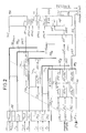
- - la Fig.1 est un bloc-diagramme fonctionnel d'un appareil programmable de transcodage unidirectionnel selon l'invention ;
- - la Fig.2 montre une organisation simplifiée de tables de transcodage incluses dans un appareil de transcodage pour la mise en oeuvre du procédé selon l'invention ;
- - la Fig.3 montre l'utilisation d'une table d'index pour réduire la taille des tables de transcodage utilisées pour l'identification de messages ; et
- - la Fig.4 montre une variante préférée de l'organisation de tables de transcodage mémorisant les messages transcodés.
- - Fig.1 is a functional block diagram of a programmable unidirectional transcoding device according to the invention;
- - Fig.2 shows a simplified organization of transcoding tables included in a transcoding device for the implementation of the method according to the invention;
- - Fig.3 shows the use of an index table to reduce the size of the transcoding tables used for message identification; and
- - Fig.4 shows a preferred variant of the organization of transcoding tables storing the transcoded messages.
Dans la description de la structure et du fonctionnement d'un appareil programmable de transcodage unidirectionnel AT suivant l'invention, on considère, à titre d'exemple, un transcodage unidirectionnel à réaliser entre un premier système numérique de traitement de données S1 transmettant des messages et un second système numérique de traitement de données S2 en attente de ces messages. A partir d'un appareil de transcodage unidirectionnel, l'homme du métier peut réaliser un appareil de transcodage bidirectionnel, en doublant des tables de transcodage et en assurant un traitement en temps partagé pour les deux sens de transmission et le contrôle de flux global de l'appareil.In the description of the structure and operation of a programmable unidirectional AT transcoding device according to the invention, we consider, by way of example, a unidirectional transcoding to be carried out between a first digital data processing system S1 transmitting messages and a second digital data processing system S2 waiting for these messages. From a unidirectional transcoding device, a person skilled in the art can produce a bidirectional transcoding device, by doubling transcoding tables and ensuring time-sharing processing for the two directions of transmission and the overall flow control of the device.
Les premier et second systèmes S1 et S2 utilisent respectivement des premier et second alphabets composés de caractères éditables pour la plupart et de commandes auxquels correspondent des mots binaires ayant un nombre de bits B déterminé, toutes les combinaisons binaires possibles de B bits pouvant être utilisées par les premier et second alphabets.The first and second systems S1 and S2 respectively use first and second alphabets composed of characters which are for the most part editable and of commands to which correspond binary words having a number of bits B determined, all the possible binary combinations of B bits can be used by the first and second alphabets.
Les commandes sont, par exemple, des commandes utilitaires telles, que "action du buzzer", "retour chariot", et "saut de ligne" notées respectivement "BEL", "CR", et "LF" dans la plupart des alphabets normalisés existants. Par la suite dans la description le terme de caractère est utilisé, comme il est d'usage, indifféremment pour un caractère éditable ou pour une commande.The commands are, for example, utility commands such as "buzzer action", "carriage return", and "line feed" noted respectively "BEL", "CR", and "LF" in most standard alphabets existing. Subsequently in the description the term character is used, as is customary, either for an editable character or for an order.
En référence à la Fig.1, le système S1 transmet à l'appareil programmable de transcodage AT des messages entrants ME à travers une liaison de transmission de données unidirectionnelles 111. Un message entrant est constitué d'un unique mot entrant (CE) ou d'une suite de N mots binaires entrants [(CE₁), (CE₂),... (CEn),... (CEN)], N étant un entier variable pouvant varier de 1 à un nombre entier maximum prédéterminé Nmax et représentant la longueur du message entrant. A chacun des mots entrants d'une suite de mots correspond un rang n, n étant un entier compris entre 1 et N, représentatif de son ordre chronologique d'arrivée dans l'appareil de transcodage AT par rapport au premier mot reconnu (CE₁) de la suite entrante. Aux mots entrants (CE) et (CE₁), (CE₂),... (CEn),... (CEN) correspondent dans l'alphabet du système S1 des caractères CE et CE₁, CE₂,... CEn,... CEN respectivement.With reference to FIG. 1, the system S1 transmits incoming messages ME to the programmable transcoding device AT via a unidirectional
Chaque mot entrant est reçu dans l'appareil de transcodage AT par une interface d'entrée 1 via la liaison de transmission 111. Une liaison de dialogue 111a est prévue entre le système S1 et l'interface 1 afin que celle-ci puisse inviter le système S1, en cas de nécessité, à suspendre la transmission. Cette liaison de dialogue 111a peut être supprimée par l'utilisation de caractères de commande, lesquels peuvent être des caractères, "XON" et "XOFF", pour autorisier et suspendre la transmission respectivement. Les caractères de commande, "XON" et "XOFF", sont alors transmis au système S1 via la liaison de transmission 111, qui dans ce cas est bidirectionnelle.Each incoming word is received in the transcoding device AT by an
L'interface 1 comprend un adaptateur d'entrée 11 et une file d'attente 12. L'adaptateur d'entrée 11 sert à adapter la liaison de transmission de données 111, qui peut être de type série ou de type parallèle, à des bus internes de l'appareil de transcodage AT. Par exemple, dans le cas d'une liaison de transmission 111 de type série, l'adaptateur 111 peut être un circuit spécialisé pour ce type de transmission, tel qu'un UART (Universal Asynchronous Receiver Transmitter), ou plus simplement un registre série-parallèle ; dans le cas d'une liaison de transmission 111 parallèle, des mémoires tampons d'entrée, dites "buffers", peuvent convenir.The
La file d'attente 12 reçoit les mots entrants délivrés par l'adaptateur 11 en format parallèle à travers un bus 112. La file d'attente 12 est un registre de stockage de type FIFO (First in, First out).The
Pour chaque mot entrant (CE) reçu, l'adaptateur 11 délivre à travers une liaison 32 un signal de détection de mot vers une unité de gestion d'échange 3. Le mot entrant (CE) est ensuite présenté en sortie sur le bus 112 relié à l'entrée de la file d'attente 12. L'unité de gestion 3 étant avisée de l'arrivée d'un mot à travers la liaison 32, un signal de commande de stockage est appliqué à la file d'attente 12, par une liaison 33, pour mémoriser dans la file 12 le mot entrant (CE) présent dans le bus 112.For each incoming word (CE) received, the
Des moyens de traitement et de commande sont inclus dans l'appareil de transcodage AT sous la forme d'une unité centrale 4. L'unité 4 contient une mémoire morte 42 du type PROM contenant des micro-instructions pour exécuter un algorithme de transcodage et pour commander l'unité de gestion d'échange 3. L'unité centrale 4 délivre des mots de commande à l'unité de gestion 3 par un bus de commande 41. L'unité centrale 4 est constamment informée de l'état de l'appareil de transcodage par un mot d'état délivré par l'unité de gestion d'échange 3 dans un bus d'état 36. L'unité centrale 4 étant prête à lire un mot entrant (CE) stocké dans la file d'attente 12, afin de procéder à un traitement de transcodage, elle transmet à destination de l'unité de gestion d'échange 3 un mot de commande par le bus de commande 41. L'unité de gestion 3 décode ce mot de commande, génère un signal par la liaison 33 pour signifier à la file d'attente 12 de présenter sur un bus de sortie 122 connecté à une entrée 51 d'un dispositif d'aiguillage 5, le premier mot entrant (CE) par ordre chronologique d'arrivée. Le mot (CE) étant présent dans le bus 122, l'unité de gestion fournit alors, au dispositif d'aiguillage 5, un signal par une liaison 35, pour commander la connexion de l'entrée 51 sur une entrée/sortie 52 du dispositif d'aiguillage 5. L'entrée/sortie 52 est reliée à l'unité centrale 4 par un bus de données 521. L'unité centrale 4 lit le mot entrant (CE) présenté sur le bus 521.Processing and control means are included in the transcoding apparatus AT in the form of a
Le mot entrant (CE) est identifié dans l'unité centrale 4 à l'aide de tables de transcodage contenues dans une mémoire vive 43 du type RAM.The incoming word (CE) is identified in the
Le mot entrant (CE) peut être identifié comme n'ayant pas de message sortant transcodé correspondant, anquel cas, il n'est pas pris en compte. L'unité centrale 4 commande alors la lecture du mot entrant suivant dans la file d'attente 12 de la manière qui vient d'être décrite, en transmettant un mot de commande à l'unité de gestion d'échange 3 par le bus 41.The incoming word (CE) can be identified as having no corresponding transcoded outgoing message, in which case it is not taken into account. The
Le mot entrant (CE) peut être identifié comme étant le premier mot (CE₁) d'une suite de N mots entrants connue par l'unité centrale 4. L'unité centrale 4 procède alors, à la lecture et à l'identification des mots suivants de la suite entrante.The incoming word (CE) can be identified as the first word (CE₁) of a series of N incoming words known by the
Au mot entrant (CE) ou à la suite de N mots entrants [(CE₁), (CE₂),... (CEn),... (CEN)] constituant un message entrant ME peut correspondre un message sortant transcodé MS composé d'un mot sortant (CS) ou d'une suite de M mots sortants transcodés [(CS₁), (CS₂),... (CSm), ...(CSM)] où m est entier compris entre 1 et M, et M est un entier variable, en général différent de l'entier N, pouvant varier de 0 à un nombre maximum prédéterminé Mmax et représentant la longueur du message sortant MS.The incoming word (CE) or following N incoming words [(CE₁), (CE₂), ... (CE n ), ... (CE N )] constituting an incoming message ME can correspond to an outgoing transcoded message MS composed of an outgoing word (CS) or of a sequence of M outgoing transcoded words [(CS₁), (CS₂), ... (CS m ), ... (CS M )] where m is an integer understood between 1 and M, and M is a variable integer, generally different from the integer N, which can vary from 0 to a predetermined maximum number Mmax and representing the length of the outgoing message MS.
Dans le cas où, au message entrant ME constitué du mot entrant (CE) ou de la suite de N mots entrants correspond un message sortant transcodé MS, l'unité centrale 4 fournit à l'unité de gestion d'échange 3 un autre mot de commande par le bus 41 afin de commander l'aiguillage de chacun des mots sortants du message MS vers une interface de sortie 2 transmettant des mots sortants transcodés (CS), par une liaison de transmission 211, vers le second système S2. A la réception du mot de commande, l'unité de gestion 3 provoque la connexion de l'entrée/sortie 52 du dispositif d'aiguillage 5 avec une sortie 53 du même dispositif 5, par activation de la liaison de commande 35. La sortie 53 est reliée par un bus 222 à l'entrée d'une file d'attente 22, analogue à la file d'attente 12, incluse dans l'interface de sortie 2. Chacun des mots sortants transféré est stocké, en réponse à un signal de commande délivré par l'unité de gestion 3 via une liaison de commande 38, dans la file d'attente 22, avec des mots sortants transcodés à transmettre vers le système S2.If the incoming message ME consisting of the incoming word (CE) or the sequence of N incoming words corresponds to an outgoing transcoded message MS, the
L'interface de sortie 2 comprend, outre la file d'attente 22, un adaptateur de sortie 21 connecté en sortie au second système S2 par la liaison de transmission 211 et une liaison de dialogue 211a. La liaison 211a peut, de même, que la liaison de dialogue 111a, être supprimée par l'utilisation des caractères de commande déjà cités "XON" et "XOFF". L'adaptateur 21 a pour fonction, de même que l'adaptateur d'entrée 11, d'adapter les bus internes de l'appareil de transcodage à la liaison de transmission unidirectionnelle 211, qui peut être, de même que la liaison 111, de type série ou parallèle.The
Un bus de liaison 221 fournit des mots sortants transcodés issus de la file d'attente 22 en entrée de l'adaptateur 21. Lorsque l'adaptateur 21 est prêt à transmettre un mot sortant (CS) stocké dans la file d'attente 22, il le signale à l'unité de gestion d'échange 3 par une liaison 39. L'unité de gestion 3 ordonne alors, par la liaison 38, à la file d'attente 22 de présenter en sortie sur le bus 221 un mot sortant (CS). Le mot sortant (CS) est lu par l'adaptateur 21 qui le transmet via la liaison 211 au système S2.A
L'unité de gestion d'échange 3 effectue la gestion et le contrôle des signaux échangés entre les différents circuits de l'appareil de transcodage ainsi qu'entre l'appareil de transcodage et les systèmes S1 et S2. L'unité de gestion 3 reçoit de l'unité centrale 4 un mot de commande relatif aux échanges de données à l'intérieur de l'appareil de transcodage à partir duquel sont créés différents signaux de commande envoyés aux interfaces 1 et 2 par les liaisons 31, 33, 38, et 40, ainsi qu'au dispositif d'aiguillage 5 par la liaison 35. Un mot d'état est fourni par l'unité de gestion d'échange 3 à l'unité centrale 4, à travers le bus 36 pour l'informer de tout changement intervenant dans la communication avec le système S1 ou S2.The
Dans l'unité de gestion d'échange 3 sont prévus d'une manière connue, deux compteurs d'écriture et de lecture et un comparateur associés à chacune des deux files d'attente afin de déterminer le niveau de remplissage respectif de chacune des files et de comparer lesdits niveaux à des seuils de remplissage haut et bas définis de manière à réguler les débits, d'une part entre le système S1 et l'appareil de transcodage AT et d'autre part entre l'appareil de transcodage AT et le système S2, qui, en général, sont différents.In the
Les seuils haut et bas permettent, pour chacune des files d'attente, de gérer un contrôle de flux en fonction d'un cycle d'hystérésis destiné à éviter une dégradation des performances de l'appareil lors d'oscillation autour d'un seuil unique de remplissage. Ainsi, lorsqu' une file d'attente, 12 ou 22, atteint un niveau de remplissage au moins égal au seuil haut, une détection est faite par le comparateur associé et l'unité de gestion d'échange 3 suspend le remplissage de la file concernée par arrêt de la transmission et de l'écriture de mots dans la file. L'unité de gestion d'échange 3 autorise à nouveau l'écriture de mots dans la file d'attente, lorsque le niveau de remplissage de la file d'attente devient inférieur ou égal au seuil bas. La gestion des cycles d'hystérésis par l'unité de gestion d'échange 3 est réalisée à l'aide de deux indicateurs de remplissage, un pour chacune des files d'attente, inclus dans l'unité de gestion d'échange. Un indicateur de remplissage l'une file d'attente peut prendre deux états, un état "suspension de remplissage" et un état "fonctionnement normal". Un indicateur vient à l'état "suspension de remplissage" lorsque l'unité de gestion d'échange 3 détecte un niveau de remplissage égal ou supérieur au seuil haut pour la file d'attente correspondante. Un indicateur vient à l'état "fonctionnement normal" lorsque l'unité de gestion d'échange 3 détecte un niveau de remplissage égal ou inférieur au seuil bas de la file d'attente correspondante.The high and low thresholds make it possible, for each queue, to manage a flow control according to a hysteresis cycle intended to avoid a deterioration of the performance of the device during oscillation around a threshold single filling. So when a queue, 12 or 22, reaches a filling level at least equal to the high threshold, a detection is made by the associated comparator and the
Un dépassement du seuil haut dans la file d'attente 22 provoque la transmission d'un mot d'état à destination de l'unité centrale 4, via le bus d'état 36. L'unité 4 suspend alors des écritures de mots sortants dans la file d'attente 22 et toute demande de lecture, via le bus 41, de mot contenu dans la file d'attente 12. Un dépassement de seuil haut dans la file d'attente 12 entraîne une activation de la liaison 111a vers le système S1 de manière à arrêter la transmission de mots entrants. A cet effet, l'unité de gestion d'échange 3 est reliée à l'adaptateur 11, par la liaison de commande 31.Exceeding the high threshold in the queue 22 causes the transmission of a status word intended for the
Un niveau de remplissage de la file d'attente 22 inférieur ou égal au seuil bas provoque, si l'indicateur de remplissage associé à la file d'attente 22 était positionné à l'état "suspension de remplissage", la transmission d'un mot d'état à destination de l'unité centrale 4, via le bus d'état 36. L'unité 4 reprend alors l'écriture de mots sortants dans la file d'attente 22 et les demandes de lecture de la file d'attente 12.A filling level of the queue 22 less than or equal to the low threshold causes, if the filling indicator associated with the queue 22 was set to the "filling suspension" state, the transmission of a status word intended for the
Un niveau de remplissage de la file d'attente 12 inférieur ou égal au seuil bas provoque, si l'indicateur de remplissage associé à la file d'attente 12 était positionné à l'état "suspension du remplissage", la transmission d'une commande sur la liaison 31 destinée à désactiver la liaison 111a.A filling level of the
La liaison 211a entre le système S2 et l'adaptateur 21 est prévue afin que le système S2 demande de suspendre, c'est-à-dire d'arrêter ou de différer, une transmission de mots sortants, par exemple, à la suite d' une défaillance ou d 'un remplissage de mémoires tampons dans le système S2. La demande de suspension est transmise par l'adaptateur 21 à l'unité de gestion d' échange 3, qui la valide en délivrant à l'adaptateur 21, via la liaison 40, une commande d'arrêt de transmission vers le système S2. L'appareil de transcodage continue à opérer avec le système S1 jusqu'à un éventuel arrêt causé par un dépassement de seuil haut dans la file d'attente 12.The
Lorsque la demande de suspension disparaît sur la liaison 211a, l'adapteur 21 en informe l'unité 3, qui prend en compte ce nouvel état et délivre à l'adaptateur 21, via la liaison 40, une autorisation de transmission vers le système S2.When the request for suspension disappears on the
Le fonctionnement des moyens relatifs au contrôle des flux décrit dans les paragraphes précédents correspond à une transmission unidirectionnelle sans mode écho. Dans le cas d'une transmission plus complexe les mécanismes nécessaires au contrôle des flux sont plus développés, toutefois la gestion d'hystérésis ainsi que les différents moyens décrits sont conservés.The operation of the means relating to the flow control described in the preceding paragraphs corresponds to a unidirectional transmission without echo mode. In the case of a more complex transmission, the mechanisms necessary for controlling the flows are more developed, however the management of hysteresis as well as the various means described are retained.
Les tables de transcodage sont téléchargées en mémoire vive 43 dans l'unité centrale 4 lors d'une phase préalable d'initialisation, antérieurement à la mise en opération de l'appareil de transcodage. A cet effet, une liaison 61 est prévue entre l'unité centrale 4 et un micro-ordinateur 6 ayant servi à l'élaboration des tables à partir d'une analyse des alphabets de caractères des système S1 et S2, des différentes possibilités de communication entre le système S1 et le système S2, ainsi que des éventuels conflits pouvant survenir entre les deux systèmes. Le micro-ordinateur peut, en outre, servir à la visualisation de données transmises par l'unité centrale 4 pendant les opérations de transcodage, susceptibles d'intéresser un opérateur.The transcoding tables are downloaded into
Dans les paragraphes suivants, en relation avec la Fig.2, est décrite une organisation simplifiée des tables de transcodage.In the following paragraphs, in relation to FIG. 2, a simplified organization of the transcoding tables is described.
De manière générale, l'unité centrale 4 procède pour adresser les différentes tables de transcodage, suivant des modes d'adressage dits mode d'adressage relatif et mode d'adressage indexé. Le mode d'adressage relatif consiste à fournir à un processeur, un mot d'adresse représentant un décalage à réaliser généralement par rapport à la valeur d'un compteur programme afin d'obtenir une adresse effective dans une zone mémoire. Dans le mode d'adressage indexé, le mot d'adresse est fourni au processeur avec l'adresse d'un registre dit index contenant une valeur à ajouter au mot d'adresse pour obtenir une adresse effective. L'index est situé en mémoire vive et est modifiable en cours de programme, ce qui autorise une grande souplesse d'adressage. Les modes d'adressage relatif et indexé sont d'un usage fréquent pour l'adressage de tables, car ils permettant simplement de convertir une donnée en une adresse dans une table pouvant être implantée indifféremment dans une zone mémoire.In general, the
Les tables de transcodage comprennent des tables d'entrée TE₁ à TENmax, une table de messages TM, une table index ITE pour l'adressage des tables d'entrée, et une table index ITM pour l'adressage de la table de messages.The transcoding tables include input tables TE₁ to TE Nmax , a message table TM, an ITE index table for addressing the input tables, and an ITM index table for addressing the message table.
Les tables d'entrée TE₁ à TENmax supportent une arborescence logique d'identification des messages entrants. Cette arborescence comprend différentes possibilités de cheminement aboutissant à l'identification de mots entrants isolés ou de suite de mots entrants connus par l'appareil de transcodage.The TE₁ to TE Nmax input tables support a logical tree structure for identifying incoming messages. This tree structure includes different tracking possibilities leading to the identification of isolated incoming words or a series of incoming words known by the transcoding device.
Chacune des tables d'entrée TE₁, TE₂,... TEn, ... TEN,... TENmax est localisée en mémoire vive par une adresse de début de table (TE₁), (TE₂),... (TEn),... (TEN),... (TENmax) respectivement.Each of the input tables TE₁, TE₂, ... TE n , ... TE N , ... TE Nmax is located in random access memory by a table start address (TE₁), (TE₂), ... (TE n ), ... (TE N ), ... (TE Nmax ) respectively.
Seule la table d'entrée TE₁ parmi la totalité des tables d'entrée est utilisée pour le transcodage d'un mot entrant isolé (CE) ou (CE'). Le transcodage de suite de N mots entrants fait appel aux tables d'entrée TE₁ à TEN. Les mots entrants (CE₁), (CE₂),... (CEn),... (CEN) adressent dans les tables d'entrée TE₁, TE₂,... TEn,... TEN, par rapport aux adresses de début (TE₁), (TE₂),... (TEn),... (TEN), des mots de transcodage Mt₁, Mt₂,... Mtn,... MtN respectivement. Les tables d'entrée TE₂ à TENmax ne sont utilisées que pour le transcodage des messages entrants auxquels peuvent correspondre plus d'un mot sortant, leur fonction étant différente de celle de la table d'entrée TE₁ elles peuvent également être appelées "tables de renvoi".Only the entry table TE₁ among all the entry tables is used for transcoding an isolated incoming word (CE) or (CE '). The transcoding in succession of N incoming words uses the input tables TE₁ to TE N. The incoming words (CE₁), (CE₂), ... (CE n ), ... (CE N ) address in the TE₁ input tables, TE₂, ... TE n , ... TE N , with respect to the start addresses (TE₁), (TE₂), ... (TE n ), ... (TE N ), transcoding words Mt₁, Mt₂, ... Mt n , ... Mt N respectively. The input tables TE₂ to TE Nmax are only used for transcoding incoming messages to which more than one outgoing word can correspond, their function being different from that of the input table TE₁ they can also be called "tables of referral ".
Chacune des tables d'entrée comprend autant de mots de transcodage que de mots entrants différents pouvant être délivrés par le système S1, soit 2B-1 mots de transcodage, en supposant que chaque mot entrant comprend B bits, typiquement 8 bits répartis en deux demi-octets en base numérique hexadécimale. A un mot entrant ayant la valeur notée "00H" en base numérique hexadécimale correspond un caractère, noté "NUL" dans la plupart des alphabets normalisés. Le caractère NHL, bien que pouvant être traité comme tout autre caractère, est utilisé dans les tables d'entrée, ou tables de renvoi, TE₂ à TE Nmax pour prendre en compte des messages entrants de longueur supérieure.Each of the input tables comprises as many transcoding words as different incoming words that can be delivered by the system S1, that is 2 B-1 transcoding words, assuming that each incoming word comprises B bits, typically 8 bits divided into two half-bytes in hexadecimal digital base. An incoming word having the value noted "00 H " in hexadecimal numerical base corresponds to a character, noted "NULL" in most standard alphabets. The character NHL, although it can be treated like any other character, is used in the input tables, or reference tables, TE₂ to TE Nmax to take into account incoming messages of greater length.
Chacun des mots de transcodage Mtn comprend B+1 bits et est divisé en des premier et second champs ch1 et ch2. Le premier champ ch1 est un indicateur d'indentification ; il est composé du bit de poids fort, dit le bit le plus significatif MSB. Le second champ ch2 est composé des B bits restants du mot de transcodage Mtn. Le champ ch2 est généralement une adresse utilisée par l'unité centrale pour poursuivre le traitement de transcodage ; il peut également, dans la table d'entrée TE₁, être un mot sortant transcodé (CS).Each of the transcoding words Mt n comprises B + 1 bits and is divided into first and second fields ch1 and ch2. The first field ch1 is an identification indicator; it is made up of the most significant bit, known as the most significant bit MSB. The second field ch2 is composed of the remaining B bits of the transcoding word Mt n . The field ch2 is generally an address used by the central unit to continue the transcoding processing; it can also, in the entry table TE₁, be an outgoing transcoded word (CS).
La table de messages TM est localisée en mémoire vive par une adresse de début de table (TM). Dans la table TM sont mémorisés des messages sortants transcodés constitués de mots sortants ayant chacun B bits. Un message sortant transcodé MS est précédé dans la table TM par le nombre M de mots sortants contenus dans ce message. Le nombre M et les mots sortants (CS₁), (CS₂),... (CSm),... (CSM) d'un message MS sont respectivement mémorisés à des adresses AM et AM + 1, AM + 2, ... AM + m, ... AM+M par rapport à l'adresse (TM).The message table TM is located in RAM by a table start address (TM). Transcoded outgoing messages made up of outgoing words each having B bits are stored in the table TM. A transcoded outgoing message MS is preceded in the table TM by the number M of outgoing words contained in this message. The number M and the outgoing words (CS₁), (CS₂), ... (CS m ), ... (CS M ) of a message MS are respectively stored at addresses AM and AM + 1, AM + 2 , ... AM + m, ... AM + M relative to the address (TM).
Pour une lecture d'un message sortant MS, seule l'adresse AM est fournie à l'unité centrale ; celle-ci lit le nombre M afin de déduire l'adresse AM + M de fin de message. Les mots sortants sont ensuite lus successivement à partir de l'adresse AM + 1 de début de message jusqu'à l'adresse AM + M de fin de message. Si le nombre M est égal à 0, aucun message sortant ne correspond au message entrant.For reading an outgoing message MS, only the address AM is supplied to the central unit; this reads the number M in order to deduce the address AM + M at the end of the message. The outgoing words are then read successively from the address AM + 1 at the start of the message to the address AM + M at the end of the message. If the number M is equal to 0, no outgoing message corresponds to the incoming message.
La table index ITE est une table intermédiaire utilisée par l'unité centrale pour adresser un mot de transcodage Mtn dans une table d'entrée TEn ; elle contient les adresses de début de table (TE₁) à (TENmax) des tables d'entrée TE₁ à TENmax. La table ITE se trouve en mémoire à une adresse de début (ITE). Chacune des adresses de début de table (TE₁) à (TENmax)est localisée dans la table index ITE par une adresse, A₁ à ANmax respectivement.The ITE index table is an intermediate table used by the central unit to address a transcoding word Mt n in an input table TE n ; it contains the table start addresses (TE₁) to (TE Nmax ) of the input tables TE₁ to TE Nmax . The ITE table is stored in memory at a start address (ITE). Each of the table start addresses (TE₁) to (TE Nmax ) is located in the ITE index table by an address, A₁ to A Nmax respectively.
La table index ITM est une table intermédiaire utilisée par l'unité centrale pour adresser des messages sortants transcodés MS' dans la table de message (TM) à partir de mots de transcodage Mt' de la table d'entrée TE₁. La table ITM est localisée en mémoire vive par l'adresse de début (ITM).The ITM index table is an intermediate table used by the central unit to address outgoing transcoded messages MS 'in the message table (TM) from transcoding words Mt' from the input table TE₁. The ITM table is located in RAM by the start address (ITM).
La Fig.2 montre l'utilisation des tables de transcodage par l'unité centrale pour trois cas typiques de traitement de transcodage.Fig. 2 shows the use of the transcoding tables by the central unit for three typical cases of transcoding processing.
Selon un premier cas typique CAS1, à un message entrant constitué d'un unique mot entrant (CE) correspond un message transcodé composé d'un unique mot sortant transcodé (CS). Le mot entrant (CE) adresse dans la table TE₁, par rapport à l'adresse de début de table (TE₁), un mot de transcodage Mt. Le champ ch1 du mot Mt à l'état binaire "0" indique à l'unité centrale que le second champ ch2 du mot Mt est le mot sortant transcodé (CS).According to a first typical case CAS1, an incoming message consisting of a single incoming word (CE) corresponds to a transcoded message composed of a single outgoing transcoded word (CS). The incoming word (CE) addresses in the table TE₁, with respect to the table start address (TE₁), a transcoding word Mt. The field ch1 of the word Mt in the binary state "0" indicates to the central unit that the second field ch2 of the word Mt is the outgoing transcoded word (CS).
Selon un second cas typique CAS2, à un message entrant constitué d'un unique mot entrant (CE') correspond un message sortant transcodé MS' de longueur M' différente de 1. Les champs ch1 et ch2 d'un mot de transcodage Mt' sélectionné par le mot (CE') sont alors respectivement à l'état binaire "1", contrairement au cas précédent CAS1, et égal au mot entrant (CE'). L'unité centrale utilise le mot (CE') pour adresser dans la table index ITM un mot d'adresse AM'. Le mot AM' lu par l'unité centrale est, dans la table de message TM, l'adresse du message MS' correspondant au mot (CE').According to a second typical case CAS2, an incoming message consisting of a single incoming word (CE ') corresponds to an outgoing transcoded message MS' of length M 'different from 1. The fields ch1 and ch2 of a transcoding word Mt' selected by the word (CE ') are then respectively in the binary state "1", unlike the previous case CAS1, and equal to the incoming word (CE'). The central unit uses the word (CE ') to address an address word AM' in the index table ITM. The word AM 'read by the central unit is, in the message table TM, the address of the message MS 'corresponding to the word (CE').
Selon un troisième cas typique CAS3, à un message entrant constitué d'une suite de N mots entrants [(CE₁), (CE₂),... (CEn),... (CEN)] correspond un message sortant transcodé MS comprenant une suite de M mots sortants [(CS₁), (CS₂),... (CSm),... (CSM)].According to a third typical case CAS3, an incoming message consisting of a series of N incoming words [(CE₁), (CE₂), ... (CE n ), ... (CE N )] corresponds to an outgoing transcoded message MS comprising a sequence of M outgoing words [(CS₁), (CS₂), ... (CS m ), ... (CS M )].
Le premier mot entrant (CE₁) sélectionne dans la table d'entrée TE₁ un mot de transcodage Mt₁ ayant un premier champ ch1 à l'état binaire "1". Le second champ ch2 du mot Mt₁ est différent du mot entrant (CE₁), contrairement au cas précédent CAS 2, ce qui permet à l'unité centrale de reconnaître le mot (CE₁) comme étant le premier mot d'une suite de mots connue. Le champ ch2 du mot Mt₁ est égal à l'adresse A₂ situant l'adresse de début (TE₂) dans la table d'index ITE. Un second mot entrant (CE₂) sélectionne alors dans la table TE₂, par rapport à l'adresse de début (TE₂) lue dans la table index ITE, un second mot de transcodage Mt₂ ayant un premier champ ch1 à l'état binaire "1". Le champ ch1 du mot Mt₂ à l'état binaire "1" confirme le cheminement d'identification suivi et indique à l'unité centrale qu'un troisième mot entrant (CE₃) est attendu. Le champ ch2 du mot Mt₂ est l'adresse A₃ situant dans la table ITE, l'adresse de début (TE₃) de la table d'entrée TE₃.The first incoming word (CE₁) selects in the input table TE₁ a transcoding word Mt₁ having a first field ch1 in the binary state "1". The second field ch2 of the word Mt₁ is different from the incoming word (CE₁), unlike the
Le mot entrant (CE₃) est utilisé de manière analogue au mot (CE₂) pour sélectionner dans la table d'entrée TE₃ un mot de transcodage Mt₃ dont le champ ch1 à l'état binaire "1" indique à l'unité centrale de poursuivre un même processus, jusqu'au mot entrant (CEN). Le mot entrant (CEN) sélectionne dans la table TEN un mot de transcodage MtN dont le champ ch1 à l'état binaire "0" permet à l'unité centrale de reconnaître le mot (CEN) comme étant le dernier mot de la suite connue. Le champ ch2 égal alors à une adresse AM de la table de messages TM est lu par l'unité centrale afin d'adresser dans la table TM le message sortant transcodé MS correspondant. Le nombre M de mots du message MS mémorisé à l'adresse AM est compris entre 0 et Mmax. Pour un message MS correspondant, ayant un seul mot, le nombre M est égal à 1. Un mot unique sortant (CS₁) est ainsi lu, à l'adresse AM+1.The incoming word (CE₃) is used analogously to the word (CE₂) to select from the TE₃ input table a transcoding word Mt₃ whose field ch1 in binary state "1" indicates to the central unit to continue the same process, up to the incoming word (CE N ). The incoming word (CE N ) selects in the table TE N a transcoding word Mt N whose field ch1 in binary state "0" allows the central unit to recognize the word (CE N ) as being the last word subsequently known. The field ch2 then equal to an address AM of the message table TM is read by the central unit in order to address in the table TM the outgoing transcoded message MS corresponding. The number M of words of the message MS stored at the address AM is between 0 and Mmax. For a corresponding MS message, having a single word, the number M is equal to 1. A single outgoing word (CS₁) is thus read, at the address AM + 1.
Un mot entrant suivant le mot (CEN) adresse à nouveau la table d'entrée TE₁.An incoming word following the word (CE N ) again addresses the entry table TE₁.
Le cas CAS3 qui vient d'être décrit, concerne un cheminement dans les tables d'entrée TE₁ à TENmax aboutissant directement à l'identification d'une suite de mots entrants comme étant un message entrant à transcoder connu par l'unité centrale. Toutefois après un mot entrant (CEn) identifié comme le nième mot entrant d'une suite de mots connue, peut se présenter un mot entrant (CEn+1) qui n'est pas le (n+1)ième mot attendu de la suite de mots entrants connue. Le mot entrant (CEn+1) adresse alors dans la table d'entrée TEn+1 un mot de transcodage Mtn+1 ayant une valeur déterminée, par exemple "00H".The case CAS3 which has just been described relates to a path in the input tables TE₁ to TE Nmax leading directly to the identification of a series of incoming words as being an incoming message to be transcoded known by the central unit. However after an incoming word (CE n ) identified as the n th incoming word of a known sequence of words, an incoming word (CE n + 1 ) may occur which is not the (n + 1) th expected word from the known sequence of incoming words. The incoming word (CE n + 1 ) then addresses in the input table TE n + 1 a transcoding word Mt n + 1 having a determined value, for example "00 H ".
La valeur "00H" ainsi déterminée est pour l'unité centrale un code d'échec lui indiquant, compte tenu du dernier mot entrant (CEn+1), soit un échec dans le transcodage soit l'existence d'un message connu de longueur supérieure. L'unité centrale initialise alors les mots de transcodage Mt₁ à Mtn+1 avec de nouvelles valeurs contenues dans une table associée aux tables d'entrée. Un nouvel essai de transcodage est entrepris à partir des mots entrants (CE₁) à (CEn+1) préalablement sauvegardés dans une table de mots entrants. La table associée aux tables d'entrée contient les différents mots de transcodage possibles à une même adresse dans une table d'entrée ; ces différents mots correspondent à différentes possibilités de cheminements. Différentes possibilités de cheminement peuvent être essayées par l'unité centrale avant d'aboutir au transcodage des mots (CE₁) à (CEp), où p est un entier supérieur ou égal à 1, par un ou des messages sortants transcodés.The value "00 H " thus determined is for the central unit a failure code indicating to it, taking into account the last incoming word (CE n + 1 ), either a failure in the transcoding or the existence of a known message longer in length. The central unit then initializes the transcoding words Mt₁ to Mt n + 1 with new values contained in a table associated with the input tables. A new transcoding test is undertaken from the incoming words (CE₁) to (CE n + 1 ) previously saved in an incoming word table. The table associated with the input tables contains the different possible transcoding words at the same address in an input table; these different words correspond to different possibilities of pathways. Different tracking possibilities can be tried by the central unit before transcoding the words (CE₁) to (CE p ), where p is an integer greater than or equal to 1, by one or more transcoded outgoing messages.
D'autres organisations des tables de transcodage sont possibles de manière à adapter un transcodage à réaliser à des possibilités d'adressage de l'unité centrale forcément limitées et pour autoriser une grande souplesse dans le choix des valeurs affectées à des mots d'adresse, par rapport aux différentes valeurs possibles des mots entrants.Other organizations of the transcoding tables are possible so as to adapt a transcoding to be carried out to addressing possibilities of the central unit necessarily limited and to allow great flexibility in the choice of the values assigned to address words, with respect to the different possible values of the incoming words.
La taille des tables d'entrée TE₂ à TENmax décrites précédemment peut être sensiblement réduite par l'utilisation de tables d'index.The size of the input tables TE₂ to TE Nmax described above can be significantly reduced by the use of index tables.
En effet, un mot entrant (CEp) adressant une table d'entrée TEp, où p est un entier compris entre 2 et Nmax, et identifié avec succès, c'est-à-dire identifié comme étant bien le pième mot entrant de la suite de mot attendu, est généralement compris entre un mot entrant minimum (CEp)mini et un mot entrant maximum (CEp)maxi conduisant à des succès dans l'identification par la table TEp. Un table d'index ITEpassociée à la table TEp contenant les mots (CEp)mini et (CEp)maxi et utilisée pour l'adressage de la table TEp permet de limiter la taille de la table d'entrée TEp au nombre de mots compris entre (CEp)mini et (CEp)maxi.Indeed, an incoming word (CE p ) addressing an input table TE p , where p is an integer between 2 and Nmax, and successfully identified, that is to say identified as being the p th word entering the expected word sequence, is generally between a minimum incoming word (CE p ) minimum and a maximum incoming word (CE p ) maximum leading to success in the identification by the table TE p . An ITE p index table associated with the TE p table containing the words (CE p ) mini and (CE p ) max and used for addressing the TE p table makes it possible to limit the size of the input table TE p the number of words between (CE p ) minimum and (CE p ) max .
Comme montré à la Fig.2, la position de la table d'index ITEp associée à la table TEp est de préférence contiguë à la table TEp et prédède celle-ci dans la zone mémoire RAM de l'appareil. Les mots (CEp)mini et (CEp)maxi sont ainsi adressés en effectuant respectivement un décalage de -2 et -1 par rapport à l'adresse de début de table (TEp) de la table TEp.As shown in Fig.2, the position of the ITE p index table associated with the TE p table is preferably contiguous to the TE p table and precedes the latter in the RAM memory area of the device. The words (CE p ) mini and (CE p ) max are thus addressed by making an offset of -2 and -1 respectively with respect to the table start address (TE p ) of the TE p table.
Un mot entrant (CEp) lu par l'unité centrale est d'abord comparé aux mots (CEp)mini et (CEp)maxi. Si le mot entrant (CEp) n'est pas compris dans la fourchette définie par les mots (CEp)mini et (CEp)maxi, l'unité centrale en déduit directement un échec de l'essai de transcodage en cours. Si le mot entrant (CEp) est bien compris entre les mots (CEp)mini et (CEp)maxi, le mot de transcodage MTp correspondant est adressé dans la table d'entrée TEp à partir de l'adresse de début (TEp) par le mot (CEp)-(CEp)mini représentant la différence numérique entre les mots (CEp) et (CEp)mini.An incoming word (CE p ) read by the central unit is first compared to the words (CE p ) minimum and (CE p ) maximum . If the incoming word (CE p ) is not included in the range defined by the words (CE p ) minimum and (CE p ) maximum , the central unit directly deduces a failure of the transcoding test in progress. If the incoming word (CE p ) is well between the words (CE p ) minimum and (CE p ) maximum , the corresponding transcoding word MT p is addressed in the input table TE p from the address of start (TE p ) with the word (CE p ) - (CE p ) mini representing the numerical difference between the words (CE p ) and (CE p ) mini .
La table de message TM peut être remplacée par Nmax tables de messages TM₁ à TMNmax respectivement associées aux tables d'entrée TE₁ à TENmax.The message table TM can be replaced by Nmax message tables TM₁ to TM Nmax respectively associated with the input tables TE₁ to TE Nmax .
En référence à la Fig.4, une table d'entrée TEq, où q est un entier compris entre 1 et Nmax, adresse dans la table de message TMq qui lui est associée, un message sortant MS" à l'aide de tables d'index respectives, IM1q et IM2q.Referring to Fig.4, an input table TE q , where q is an integer between 1 and Nmax, address in the message table TM q associated with it, an outgoing message MS "using respective index tables, IM1 q and IM2 q .
La table d'index IM1q est localisée par son adresse de début (IM1q) et est composée de 3 mots de B bits, Mtqmini, Mtqmaxi, et Lq. Le mot Mtqmini est placé à l'adresse de début de table (IM1q) et est égal à un mot de transcodage minimum de la table d'entrée TEq ayant un indicateur ch1 = "0" et auquel correspond un message sortant dans la table de messages TMq. Le mot Mtqmaxi est placé à l'adresse suivante (IM1q)+1 et est égal à un mot de transcodage maximum de la table d'entrée TEq ayant un indicateur ch1 = "0' et auquel correspond un message sortant dans la table de messages TMq ; il est essentiellement utilisé pendant la phase de génération et d'initialisation des tables pour des vérifications ou des modifications de tables.The IM1 q index table is located by its start address (IM1 q ) and is made up of 3 B-bit words, Mt qmini , Mt qmaxi , and L q . The word Mt qmini is placed at the table start address (IM1 q ) and is equal to a minimum transcoding word from the input table TE q having an indicator ch1 = "0" and to which corresponds an outgoing message in the message table TM q . The word Mt qmaxi is placed at the following address (IM1 q ) +1 and is equal to a maximum transcoding word from the input table TE q having an indicator ch1 = "0 'and to which corresponds an outgoing message in the message table TM q ; it is mainly used during the phase of generation and initialization of tables for verifications or modifications of tables.
La table d'index IM2q comprend Lq mots de B bits. Chacun des mots de la table d'index IM2q est une adresse d'un message sortant dans la table de messages correspondante TMq, par rapport à une adresse de début (TMq) de la table de messages.The index table IM2 q includes L q words of B bits. Each of the words in the index table IM2 q is an address of an outgoing message in the corresponding message table TM q , relative to a start address (TM q ) of the message table.
Une table de messages TMq est localisée par l'adresse de début de table (TMq). Un message sortant MS" de la table de message est adressé dans la table de messages TMq par un mot d'adresse AM" mémorisé dans la table index IM2q.A TM q message table is located by the table start address (TM q ). An outgoing message MS "from the message table is addressed in the message table TM q by an address word AM" stored in the index table IM2 q .
Un mot de transcodage MTq de la table d'entrée TEq auquel correspond un message sortant MS" est compris entre les mots Mtqmini et Mtqmaxi. L'unité centrale après avoir vérifié que le mot Mtq est bien compris entre les mots Mtqmini et Mtqmaxi, lit le mot d'adresse AM" dans la table d'index IM2q en l'adressant à partir de l'adresse de début (IM2q) par la différence numérique des mots Mtq et Mtqmini, soit Mtq-Mtqmini.A transcoding word MT q from the input table TE q to which corresponds an outgoing message MS "is included between the words Mt qmini and Mt qmaxi . The central unit after checking that the word Mt q is understood between the words Mt qmini and Mt qmaxi , read the address word AM "in the index table IM2 q by addressing it from the start address (IM2 q ) by the numerical difference of the words Mt q and Mt qmini , let Mt q -Mt qmini .
De préférence les tables IM1q, IM2q, et TMq, sont contiquës dans la zone mémoire RAM de l'appareil, comme montré à la Fig.4. En effet, l'unité centrale peut alors déduire les adresses de débuts de tables (IM2q) et (TMq) à partir de l'adresse (IM1q), de la taille invariable de la table IM1q fixée à 3 mots, et du mot Lq représentant la taille de la table IM2q, et réduit de ce fait le nombre d'opération de lecture nécessaire pour l'adressage des messages sortants.Preferably the tables IM1 q , IM2 q , and TM q , are contics in the RAM memory area of the device, as shown in Fig.4. Indeed, the central unit can then deduce the addresses of the start of tables (IM2 q ) and (TM q ) from the address (IM1 q ), from the invariable size of the table IM1 q fixed at 3 words, and of the word L q representing the size of the table IM2 q , and thereby reduces the number of read operations necessary for the addressing of outgoing messages.
L'appareil de transcodage selon l'invention peut subir diverses modifications pour l'adapter à différents modes de fonctionnement ou pour minimiser son coût. L'unité de gestion d'échange 3, dans la réalisation qui vient d'être décrite, peut être réalisée en logique câblée à l'aide de décodeurs, bascules et portes logiques, ou incluse dans l'unité centrale assurant la gestion d'échange à partir d'un microprogramme contenu en mémoire morte. Dans une réalisation plus perfectionnée, notamment pour un appareil de transcodage bidirectionnel, l'unité de gestion d'échange peut être réalisée à l'aide d'un microcontrôleur à microprocesseur, esclave de l'unité centrale et gérant les communications de manière autonome.The transcoding device according to the invention can undergo various modifications to adapt it to different operating modes or to minimize its cost. The
Pour certaines réalisations ne nécessitant qu'une zone de mémoire réduite pour le traitement de transcodage, l'unité centrale peut contenir, en mémoire morte, un logiciel de génération des tables de transcodage. Le micro-ordinateur 6 peut alors être remplacé par un simple terminal de dialogue, ou un clavier hexadécimal muni d'afficheurs, pour introduire dans l'appareil de transcodage différents paramètres et données à saisir relatifs aux systèmes S1 et S2 et au mode de fonctionnement désiré.For certain embodiments requiring only a reduced memory area for transcoding processing, the central unit can contain, in read-only memory, software for generating transcoding tables. The
De plus, si aucun moyen pour visualiser et surveiller des opérations de transcodage en cours n'est nécessaire, le terminal ou le micro-ordinateur 6 peut n'être connecté à l'appareil de transcodage que pendant la phase d'initialisation préalable, la connexion du terminal à l'appareil pouvant alors être effectuée par l'intermédiaire de l'interface 1 ou 2.In addition, if no means for viewing and monitoring transcoding operations in progress is necessary, the terminal or the
Claims (10)
des premier et second moyens d'interfaçage (1, 2) pour relier l'appareil à des premier et second systèmes numériques incompatibles ayant à communiquer entre eux (S1, S2), à travers des liaisons (111, 211) par lesquelles transitent les messages entrants et les messages sortants transcodés,
des moyens de traitement (4) comprenant les tables de transcodage (TE, TM, ITE, ITM) et un algorithme programmé pour identifier les messages entrants et pour délivrer consécutivement les messages sortants transcodés correspondants,
des moyens de commutation (5) pour connecter alternativement les premier et second moyens d'interfaçage (1, 2) aux moyens de traitement (4) afin que les moyens de traitement (4) reçoivent les messages entrants délivrés par les moyens d'interfaçage (1, 2) et transmettent en réponse les messages sortants transcodés correspondants aux moyens d'interfaçage (1, 2), et
des moyens de gestion d'échange (3) pour gérer les moyens d'interfaçage (1, 2) et les moyens de commutation (5) en fonction d'un mot binaire de commande délivré par les moyens de traitement (4) et pour réguler le débit des messages échangés entre l'appareil et lesdits systèmes (S1, S2) en fonction d'informations fournies par les moyens d'interfaçage (1, 2).4 - transcoding apparatus for implementing the method according to any one of claims 1 to 3, characterized in that it comprises:
first and second interfacing means (1, 2) for connecting the apparatus to first and second incompatible digital systems having to communicate with each other (S1, S2), through links (111, 211) through which the incoming messages and transcoded outgoing messages,
processing means (4) comprising the transcoding tables (TE, TM, ITE, ITM) and an algorithm programmed to identify the incoming messages and to deliver the corresponding transcoded outgoing messages consecutively,
switching means (5) for alternately connecting the first and second interfacing means (1, 2) to the processing means (4) so that the processing means (4) receive the incoming messages delivered by the interfacing means (1, 2) and transmit in response the transcoded outgoing messages corresponding to the interfacing means (1, 2), and
exchange management means (3) for managing the interfacing means (1, 2) and the switching means (5) as a function of a binary command word delivered by the processing means (4) and for regulate the rate of messages exchanged between the device and said systems (S1, S2) according to information provided by the interfacing means (1, 2).
Applications Claiming Priority (2)
| Application Number | Priority Date | Filing Date | Title |
|---|---|---|---|
| FR8618099A FR2608806B1 (en) | 1986-12-23 | 1986-12-23 | PROGRAMMABLE METHOD AND APPARATUS FOR TRANSCODING CHARACTER STRINGS |
| FR8618099 | 1986-12-23 |
Publications (2)
| Publication Number | Publication Date |
|---|---|
| EP0272969A1 true EP0272969A1 (en) | 1988-06-29 |
| EP0272969B1 EP0272969B1 (en) | 1992-05-20 |
Family
ID=9342251
Family Applications (1)
| Application Number | Title | Priority Date | Filing Date |
|---|---|---|---|
| EP87402737A Expired - Lifetime EP0272969B1 (en) | 1986-12-23 | 1987-12-02 | Method and programmable apparatus for transcribing strings of characters |
Country Status (4)
| Country | Link |
|---|---|
| US (1) | US4866445A (en) |
| EP (1) | EP0272969B1 (en) |
| DE (1) | DE3779278D1 (en) |
| FR (1) | FR2608806B1 (en) |
Cited By (1)
| Publication number | Priority date | Publication date | Assignee | Title |
|---|---|---|---|---|
| EP0644660A1 (en) * | 1993-09-14 | 1995-03-22 | Matsushita Electric Industrial Co., Ltd. | Variable length coder |
Families Citing this family (26)
| Publication number | Priority date | Publication date | Assignee | Title |
|---|---|---|---|---|
| US5231599A (en) * | 1988-12-01 | 1993-07-27 | Bull Hn Information Systems Inc. | Semantic interpreter for an incoming data stream |
| US5006849A (en) * | 1989-07-26 | 1991-04-09 | Astro, Inc. | Apparatus and method for effecting data compression |
| US5050121A (en) * | 1990-01-22 | 1991-09-17 | Vaughan H W | Communication system which uses characters that represent binary-coded decimal numbers |
| JP2639169B2 (en) * | 1990-04-09 | 1997-08-06 | 三菱電機株式会社 | Numerical control unit |
| DE69123660T2 (en) * | 1990-08-13 | 1997-04-17 | Fujitsu Ltd | Data compression method and device |
| JPH0495878A (en) * | 1990-08-14 | 1992-03-27 | Sony Corp | Peak value detection circuit |
| US5794144A (en) * | 1994-03-11 | 1998-08-11 | Bellsouth Corporation | Methods and apparatus for communicating data via a cellular mobile radiotelephone system |
| US5572207A (en) * | 1994-09-23 | 1996-11-05 | International Business Machines Corporation | Method and apparatus for numeric-to-string conversion |
| JP3495122B2 (en) * | 1995-01-11 | 2004-02-09 | 富士通株式会社 | Portable terminal device |
| US5793869A (en) * | 1996-10-11 | 1998-08-11 | Claflin, Jr.; Raymond E. | Method and apparatus for encoding and data compressing text information |
| US6311056B1 (en) * | 1998-05-21 | 2001-10-30 | Cellemetry Llc | Method and system for expanding the data capacity of a cellular network control channel |
| US6311060B1 (en) | 1998-05-21 | 2001-10-30 | Cellemetry Llc | Method and system for registering the location of a mobile cellular communications device |
| US6738647B1 (en) | 1999-04-23 | 2004-05-18 | Numerex Corporation | Method and system for expanding the data payload of data messages transported via a cellular network control channel |
| US6401132B1 (en) | 1999-08-03 | 2002-06-04 | International Business Machines Corporation | Subchaining transcoders in a transcoding framework |
| US6718177B1 (en) | 1999-09-20 | 2004-04-06 | Cellemetry, Llc | System for communicating messages via a forward overhead control channel for a programmable logic control device |
| US7783508B2 (en) | 1999-09-20 | 2010-08-24 | Numerex Corp. | Method and system for refining vending operations based on wireless data |
| US6856808B1 (en) | 1999-10-29 | 2005-02-15 | Cellmetry, Llc | Interconnect system and method for multiple protocol short message services |
| US6313768B1 (en) * | 2000-03-31 | 2001-11-06 | Siemens Information And And Communications Networks, Inc. | System and method for trace diagnostics of telecommunications systems |
| US6388589B1 (en) * | 2000-07-17 | 2002-05-14 | Trw Inc. | Programmable video interface |
| US7245928B2 (en) | 2000-10-27 | 2007-07-17 | Cellemetry, Llc | Method and system for improved short message services |
| US6718237B1 (en) | 2002-03-28 | 2004-04-06 | Numerex Investment Corp. | Method for reducing capacity demands for conveying geographic location information over capacity constrained wireless systems |
| US7323970B1 (en) | 2004-01-21 | 2008-01-29 | Numerex Corporation | Method and system for remote interaction with a vehicle via wireless communication |
| WO2007136723A2 (en) | 2006-05-17 | 2007-11-29 | Numerex Corp. | System and method for prolonging wireless data product's life |
| EP2118858A4 (en) | 2007-02-06 | 2010-03-31 | Numerex Corp | Service escrowed transportable wireless event reporting system |
| US8583626B2 (en) | 2012-03-08 | 2013-11-12 | International Business Machines Corporation | Method to detect reference data tables in ETL processes |
| US8954376B2 (en) * | 2012-03-08 | 2015-02-10 | International Business Machines Corporation | Detecting transcoding tables in extract-transform-load processes |
Citations (3)
| Publication number | Priority date | Publication date | Assignee | Title |
|---|---|---|---|---|
| US3082406A (en) * | 1957-08-08 | 1963-03-19 | Ibm | Decoding device |
| US4425626A (en) * | 1979-11-29 | 1984-01-10 | Honeywell Information Systems Inc. | Apparatus for translation of character codes for application to a data processing system |
| EP0196191A2 (en) * | 1985-03-20 | 1986-10-01 | Sony Corporation | Method and apparatus for transforming prestel codes to naplps codes |
Family Cites Families (3)
| Publication number | Priority date | Publication date | Assignee | Title |
|---|---|---|---|---|
| US3701111A (en) * | 1971-02-08 | 1972-10-24 | Ibm | Method of and apparatus for decoding variable-length codes having length-indicating prefixes |
| US3925780A (en) * | 1973-12-26 | 1975-12-09 | Ibm | Apparatus for data compression encoding and decoding |
| US4644545A (en) * | 1983-05-16 | 1987-02-17 | Data General Corporation | Digital encoding and decoding apparatus |
-
1986
- 1986-12-23 FR FR8618099A patent/FR2608806B1/en not_active Expired
-
1987
- 1987-12-02 DE DE8787402737T patent/DE3779278D1/en not_active Expired - Lifetime
- 1987-12-02 EP EP87402737A patent/EP0272969B1/en not_active Expired - Lifetime
- 1987-12-23 US US07/137,141 patent/US4866445A/en not_active Expired - Fee Related
Patent Citations (3)
| Publication number | Priority date | Publication date | Assignee | Title |
|---|---|---|---|---|
| US3082406A (en) * | 1957-08-08 | 1963-03-19 | Ibm | Decoding device |
| US4425626A (en) * | 1979-11-29 | 1984-01-10 | Honeywell Information Systems Inc. | Apparatus for translation of character codes for application to a data processing system |
| EP0196191A2 (en) * | 1985-03-20 | 1986-10-01 | Sony Corporation | Method and apparatus for transforming prestel codes to naplps codes |
Non-Patent Citations (1)
| Title |
|---|
| IBM TECHNICAL DISCLOSURE BULLETIN, vol. 19, no. 6, novembre 1976, pages 1963-1964, New York, US; J.L. GAUDET et al.: "Code translation algorithm" * |
Cited By (2)
| Publication number | Priority date | Publication date | Assignee | Title |
|---|---|---|---|---|
| EP0644660A1 (en) * | 1993-09-14 | 1995-03-22 | Matsushita Electric Industrial Co., Ltd. | Variable length coder |
| US5638067A (en) * | 1993-09-14 | 1997-06-10 | Matsushita Electric Industrial Co., Ltd. | Variable length coder |
Also Published As
| Publication number | Publication date |
|---|---|
| DE3779278D1 (en) | 1992-06-25 |
| FR2608806B1 (en) | 1989-03-17 |
| FR2608806A1 (en) | 1988-06-24 |
| EP0272969B1 (en) | 1992-05-20 |
| US4866445A (en) | 1989-09-12 |
Similar Documents
| Publication | Publication Date | Title |
|---|---|---|
| EP0272969B1 (en) | Method and programmable apparatus for transcribing strings of characters | |
| FR2480460A1 (en) | DEVICE FOR TRANSFERRING INFORMATION BETWEEN MAIN UNITS OF A DATA PROCESSING SYSTEM AND A CENTRAL SUBSYSTEM | |
| EP0349413A1 (en) | Accounting system for portable data carriers | |
| US8320401B2 (en) | System and method to access and address high-speed interface converter devices | |
| FR2617304A1 (en) | PROGRAMMABLE INPUT / OUTPUT SEQUENCER FOR INPUT / OUTPUT PROCESSOR | |
| FR2737029A1 (en) | INTERFACE DEVICE BETWEEN A COMPUTER WITH REDUNDANT ARCHITECTURE AND A COMMUNICATION MEANS | |
| EP0889429B1 (en) | IC card reader using fast transmission protocol | |
| EP0089440B1 (en) | Method and device for the exchange of information between terminals and a central control unit | |
| FR2908002A1 (en) | SYSTEM AND METHOD FOR DYNAMIC CHANGE OF PROTOCOL ADAPTERS | |
| EP0837396B1 (en) | Atomic operation on a remote memory and device for performing this operation | |
| US20190163443A1 (en) | Hierarchical sort/merge structure using a request pipe | |
| EP0027851A1 (en) | System for controlling the duration of the time interval between data blocks in a computer-to-computer transmission system | |
| US20190163444A1 (en) | Sorting using pipelined compare units | |
| EP0632622A1 (en) | Method of temporally spacing cell transmissions belonging to messages and apparatus for carrying out the method | |
| FR2520956A1 (en) | ASYNCHRONOUS TRANSMISSION SYSTEM, IN PARTICULAR FOR INTERACTIVE VIDEOTEX SYSTEM | |
| EP1426843B1 (en) | Local, industrial or domestic network | |
| EP0561699B1 (en) | Communication method for a programmable industrial controller and interface for carrying out this method | |
| EP1051693B1 (en) | Asynchronous memory card | |
| EP0191999B1 (en) | Method of addressing in a communication network between a message-sending station and at least one receiving station, and apparatus for carrying out the method | |
| FR2651345A1 (en) | ALLOCATION SYSTEM WITH PRIORITY ORIENTATION OF A BUS. | |
| EP0507685A1 (en) | Ring coupling method for information processor | |
| EP1679608A2 (en) | Design procedure for a DMA-compatible peripheral device | |
| EP0246119A1 (en) | Optional system for protecting access to a computer | |
| EP0431683B1 (en) | Serial bus clock device | |
| EP0077864A1 (en) | Scanning device for communication lines comprising an address generator |
Legal Events
| Date | Code | Title | Description |
|---|---|---|---|
| PUAI | Public reference made under article 153(3) epc to a published international application that has entered the european phase |
Free format text: ORIGINAL CODE: 0009012 |
|
| AK | Designated contracting states |
Kind code of ref document: A1 Designated state(s): DE GB |
|
| 17P | Request for examination filed |
Effective date: 19881213 |
|
| 17Q | First examination report despatched |
Effective date: 19910709 |
|
| GRAA | (expected) grant |
Free format text: ORIGINAL CODE: 0009210 |
|
| AK | Designated contracting states |
Kind code of ref document: B1 Designated state(s): DE GB |
|
| PG25 | Lapsed in a contracting state [announced via postgrant information from national office to epo] |
Ref country code: GB Effective date: 19920520 |
|
| REF | Corresponds to: |
Ref document number: 3779278 Country of ref document: DE Date of ref document: 19920625 |
|
| GBV | Gb: ep patent (uk) treated as always having been void in accordance with gb section 77(7)/1977 [no translation filed] | ||
| PLBE | No opposition filed within time limit |
Free format text: ORIGINAL CODE: 0009261 |
|
| STAA | Information on the status of an ep patent application or granted ep patent |
Free format text: STATUS: NO OPPOSITION FILED WITHIN TIME LIMIT |
|
| 26N | No opposition filed | ||
| PG25 | Lapsed in a contracting state [announced via postgrant information from national office to epo] |
Ref country code: DE Effective date: 19931001 |