EP0274773A1 - Magnetic resonance imaging apparatus comprising a quadrature coil system - Google Patents
Magnetic resonance imaging apparatus comprising a quadrature coil system Download PDFInfo
- Publication number
- EP0274773A1 EP0274773A1 EP87202300A EP87202300A EP0274773A1 EP 0274773 A1 EP0274773 A1 EP 0274773A1 EP 87202300 A EP87202300 A EP 87202300A EP 87202300 A EP87202300 A EP 87202300A EP 0274773 A1 EP0274773 A1 EP 0274773A1
- Authority
- EP
- European Patent Office
- Prior art keywords
- coil
- imaging apparatus
- magnetic resonance
- resonance imaging
- coils
- Prior art date
- Legal status (The legal status is an assumption and is not a legal conclusion. Google has not performed a legal analysis and makes no representation as to the accuracy of the status listed.)
- Granted
Links
Images
Classifications
-
- G—PHYSICS
- G01—MEASURING; TESTING
- G01N—INVESTIGATING OR ANALYSING MATERIALS BY DETERMINING THEIR CHEMICAL OR PHYSICAL PROPERTIES
- G01N24/00—Investigating or analyzing materials by the use of nuclear magnetic resonance, electron paramagnetic resonance or other spin effects
-
- G—PHYSICS
- G01—MEASURING; TESTING
- G01R—MEASURING ELECTRIC VARIABLES; MEASURING MAGNETIC VARIABLES
- G01R33/00—Arrangements or instruments for measuring magnetic variables
- G01R33/20—Arrangements or instruments for measuring magnetic variables involving magnetic resonance
- G01R33/28—Details of apparatus provided for in groups G01R33/44 - G01R33/64
- G01R33/32—Excitation or detection systems, e.g. using radio frequency signals
- G01R33/36—Electrical details, e.g. matching or coupling of the coil to the receiver
- G01R33/3678—Electrical details, e.g. matching or coupling of the coil to the receiver involving quadrature drive or detection, e.g. a circularly polarized RF magnetic field
-
- G—PHYSICS
- G01—MEASURING; TESTING
- G01R—MEASURING ELECTRIC VARIABLES; MEASURING MAGNETIC VARIABLES
- G01R33/00—Arrangements or instruments for measuring magnetic variables
- G01R33/20—Arrangements or instruments for measuring magnetic variables involving magnetic resonance
- G01R33/28—Details of apparatus provided for in groups G01R33/44 - G01R33/64
- G01R33/32—Excitation or detection systems, e.g. using radio frequency signals
- G01R33/34—Constructional details, e.g. resonators, specially adapted to MR
- G01R33/341—Constructional details, e.g. resonators, specially adapted to MR comprising surface coils
Definitions
- the invention relates to a magnetic resonance imaging apparatus, comprising a magnet system for generating a steady magnetic field, a magnet system for generating magnetic gradient fields, an rf transmitter coil and an rf quadrature surface coil system for detecting magnetic resonance signals generated in an object.
- a magnetic resonance imaging apparatus of the kind set forth in accordance with the invention is characterized in that the quadrature rf coil system comprises a stack of two flat coils with locally a mutually perpendicular magnetic field direction as well as with a reciprocal magnetic flux which is self-compensating for each of the coils.
- a preferred embodiment utilizes a stack consisting of a butterfly coil and an ordinary coil. Use is then made of the fact that the magnetic field of a butterfly coil is directed perpendicularly to the direction of the magnetic is field of a single surface coil when both coils are situated in one and the same plane.
- butterfly coils For a more detailed description of butterfly coils, reference is made to PHN 11500, EP 218290.
- butterfly coils which are situated in a flat plane and which are geometrically rigid and suitably oriented in the transmission field, an additional advantage is obtained in that, in the case of a uniform transmission field, these coils do not require uncoupling against influencing by the transmitter coil, so that the uncoupling system will be comparatively simple. If these conditions are not adequately satisfied, uncoupling can take place in a conventional manner, for example as described in EP 164164 (PHN 11042).
- any desired coil shape can be used, for example also a rectangular butterfly coil and a round or elliptical single flat coil or a roof-shaped butterfly coil and a suitably adapted second coil. In the latter case part of the flexibility of the coil system will be lost, but a specific shape will be achieved for the system.
- a further preferred embodiment utilizes, in addition to a single flat coil, a butterfly coil whichis uncoupled by a capacitance.
- a butterfly coil whichis uncoupled by a capacitance.
- Such a coil can also be constructed as a flat flexible coil and be used as such in a quadrature coil stack in accordance with the invention.
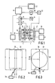
- a magnetic resonance imaging apparatus as shown in Figure 1 comprises a magnet system 2 for generating a steady, uniform magnetic field, a magnet system 4 for generating magnetic gradient fields, and power supply sources 6 and 8 for the magnet system 2 and the magnet system 4, respectively.
- a magnet coil 10 serves to generate an rf magnetic alternating field and is connected to an rf source 12.
- a surface coil system 13 For detection of magnetic resonance signals generated in an object to be examined by the rf transmission field there is included a surface coil system 13.
- the system 13 is connected to a signal amplifier 14.
- the signal amplifier 14 is connected to a phase-sensitive rectifier 16 which is connected to a central control device 18.
- the central control device 18 also controls a modulator 20 for the rf source 12, the supply source 8 for the gradient coils, and a monitor 22 for display.
- An rf oscillator 24 controls the modulator 20 as well as the phase-sensitive rectifier 16 which processes the measurement signals. Cooling can be provided by a cooling device 26 comprising cooling ducts 27.
- a cooling device of this kind may be constructed as a water cooling system for resistance coils or as a liquid helium dewar system for superconducting coils.
- the transmitter coil 10, arranged within the magnet systems 2 and 4, encloses a measurement space 28 which offers sufficient room so as to accommodate patients in medical diagnostic apparatus.
- a steady magnetic field, gradient fields for position selection of slices to be imaged, and a spatially uniform rf alternating field can be generated in the measurement space 28.
- the measurement space is shielded against interference fields by a Faraday cage 29.
- Detection coil systems composed of surface coils are not very suitable for use as transmitter coils for generating magnetic resonance signals.
- the dual function used for other types of coil, therefore, is less suitable for these coils, even though it is not precluded for specific measurements in practice.
- Figure 2 shows a quadrature surface coil system which is composed of a butterfly coil 30 and a second coil 32. Due to the geometry, the butterfly coil 30 is uncoupled for the transmission field to be used but, because uncoupling does not exist for the second coil 32, an uncoupling circuit 34 is added thereto.
- the circumferential shape of the coils can be chosen at random and may also be, for example substantially circular or elliptical.
- the single flat coil 32 is constructed so as to be circular and is again connected to an uncoupling mechanism 34.
- the composite coil 30 in this case comprises two conductors 36 and 38, having the same inductance, and a conductor 40 which is arranged symmetrically therebetween.
- the conductor 40 includes a capacitance 42 so that the coil is uncoupled in respect of transmission fields which load both coil halves to the same extent.
- the surface of the single flat coil 32 is preferably distributed exactly between the two halves of the composite coil 30.
- the surface coil as well as the second coil may be truly flat coils, which means that the conductors need not have a given dimension in a direction perpendicular to the coil surface for the sake of correct operation. Therefore, for the conductors use can be made of thin metal strips which result in an extremely well deformable coil system when they are provided with an uncoupling circuit and arranged together on a flexible support.
- coils can also be arranged in any orientation and in any location in the measurement space, regardless of the direction of a spatially uniform transmission field.
- a coil system comprising two coil stacks which are arranged opposite one another on both sides of the object to be examined.
- Coil stacks of this kind can also be used to form cascade systems in order to extend the region to be measured in an object while maintaining a comparatively good signal-to-noise ratio.
- the coil system in accordance with the invention may be included, for example in a flexible band which is locally arranged on the object to be examined.
Abstract
Description
- The invention relates to a magnetic resonance imaging apparatus, comprising a magnet system for generating a steady magnetic field, a magnet system for generating magnetic gradient fields, an rf transmitter coil and an rf quadrature surface coil system for detecting magnetic resonance signals generated in an object.
- An apparatus of this kind is known from EP 196134 (PHN 11329) which describes a method of reducing undesirable crosstalk between coils of the quadrature coil system. This increases the field of application for such a system in comparison with the previously known solution where a strictly orthogonal configuration must be maintained. The repeated detuning of a section of the coil system, however, is found to be objectionable, the more so because electronic circuits are also added to the coils for uncoupling the transmitter coil and the measuring coil device.
- It is the object of the invention to mitigate the above restrictions and to avoid the drawbacks of exact uncoupling; to achieve this, a magnetic resonance imaging apparatus of the kind set forth in accordance with the invention is characterized in that the quadrature rf coil system comprises a stack of two flat coils with locally a mutually perpendicular magnetic field direction as well as with a reciprocal magnetic flux which is self-compensating for each of the coils.
- Because in an apparatus in accordance with the invention each time two coils with mutually perpendicularly directed B fields are combined, measurement can be performed in two mutually perpendicular directions and crosstalk between the coils can be avoided by correct orientation of the coils with respect to one another. A coil system of this kind can be arranged in the measurement space with a high degree of freedom, because correct mutual orientation will now be automatically retained.
- It is to be noted that a system of this kind, be it in the form of essentially non-flat coils, is known from the Book of Abstracts of the Society of Magnetic Resonance in Medicine, Fifth Annual Meeting, August 19-22, 1986, Montreal, pages 187 and 188. In addition to their low requirements as regards space, the major advantage of flat coils consists in their high dregree of flexibility so that, for example curved coil systems are also feasible.
- A preferred embodiment utilizes a stack consisting of a butterfly coil and an ordinary coil. Use is then made of the fact that the magnetic field of a butterfly coil is directed perpendicularly to the direction of the magnetic is field of a single surface coil when both coils are situated in one and the same plane. For a more detailed description of butterfly coils, reference is made to PHN 11500, EP 218290. When use is made of butterfly coils which are situated in a flat plane and which are geometrically rigid and suitably oriented in the transmission field, an additional advantage is obtained in that, in the case of a uniform transmission field, these coils do not require uncoupling against influencing by the transmitter coil, so that the uncoupling system will be comparatively simple. If these conditions are not adequately satisfied, uncoupling can take place in a conventional manner, for example as described in EP 164164 (PHN 11042).
- The criterion of the invention will be satisfied for as long as the direction of the B field is suitably defined for each of the constituent coils and the coils can be stacked so that both magnetic fields are directed so as to be mutually perpendicular and no effective reciprocal magnetic flux is induced through the coils. Within this range of possibilities, any desired coil shape can be used, for example also a rectangular butterfly coil and a round or elliptical single flat coil or a roof-shaped butterfly coil and a suitably adapted second coil. In the latter case part of the flexibility of the coil system will be lost, but a specific shape will be achieved for the system.
- A further preferred embodiment utilizes, in addition to a single flat coil, a butterfly coil whichis uncoupled by a capacitance. Such a coil can also be constructed as a flat flexible coil and be used as such in a quadrature coil stack in accordance with the invention.
- Some preferred embodiments in accordance with the invention will be described in detail hereinafter with reference to the drawing. Therein:
- Figure 1 shows a magnetic resonance imaging apparatus comprising a stacked coil system in accordance with the invention, and
- Figures 2 and 3 show preferred embodiments of stacked coil systems for such an apparatus.
- A magnetic resonance imaging apparatus as shown in Figure 1 comprises a
magnet system 2 for generating a steady, uniform magnetic field, a magnet system 4 for generating magnetic gradient fields, andpower supply sources magnet system 2 and the magnet system 4, respectively. Amagnet coil 10 serves to generate an rf magnetic alternating field and is connected to anrf source 12. For detection of magnetic resonance signals generated in an object to be examined by the rf transmission field there is included asurface coil system 13. For reading purposes, thesystem 13 is connected to asignal amplifier 14. Thesignal amplifier 14 is connected to a phase-sensitive rectifier 16 which is connected to acentral control device 18. Thecentral control device 18 also controls amodulator 20 for therf source 12, thesupply source 8 for the gradient coils, and amonitor 22 for display. Anrf oscillator 24 controls themodulator 20 as well as the phase-sensitive rectifier 16 which processes the measurement signals. Cooling can be provided by acooling device 26 comprisingcooling ducts 27. A cooling device of this kind may be constructed as a water cooling system for resistance coils or as a liquid helium dewar system for superconducting coils. Thetransmitter coil 10, arranged within themagnet systems 2 and 4, encloses ameasurement space 28 which offers sufficient room so as to accommodate patients in medical diagnostic apparatus. Thus, a steady magnetic field, gradient fields for position selection of slices to be imaged, and a spatially uniform rf alternating field can be generated in themeasurement space 28. The measurement space is shielded against interference fields by a Faradaycage 29. - Detection coil systems composed of surface coils are not very suitable for use as transmitter coils for generating magnetic resonance signals. The dual function used for other types of coil, therefore, is less suitable for these coils, even though it is not precluded for specific measurements in practice.
- Figure 2 shows a quadrature surface coil system which is composed of a
butterfly coil 30 and asecond coil 32. Due to the geometry, thebutterfly coil 30 is uncoupled for the transmission field to be used but, because uncoupling does not exist for thesecond coil 32, anuncoupling circuit 34 is added thereto. The circumferential shape of the coils can be chosen at random and may also be, for example substantially circular or elliptical. In an embodiment as shown in Figure 3, the singleflat coil 32 is constructed so as to be circular and is again connected to anuncoupling mechanism 34. Thecomposite coil 30 in this case comprises twoconductors 36 and 38, having the same inductance, and aconductor 40 which is arranged symmetrically therebetween. Theconductor 40 includes acapacitance 42 so that the coil is uncoupled in respect of transmission fields which load both coil halves to the same extent. From a point of view of symmetry, and hence a smaller risk of residual coupling between the coils themselves, the surface of the singleflat coil 32 is preferably distributed exactly between the two halves of thecomposite coil 30. The surface coil as well as the second coil may be truly flat coils, which means that the conductors need not have a given dimension in a direction perpendicular to the coil surface for the sake of correct operation. Therefore, for the conductors use can be made of thin metal strips which result in an extremely well deformable coil system when they are provided with an uncoupling circuit and arranged together on a flexible support. These coils can also be arranged in any orientation and in any location in the measurement space, regardless of the direction of a spatially uniform transmission field. For suitable detection of, for example regions which are situated deeper within the object, use can be made of such a coil system comprising two coil stacks which are arranged opposite one another on both sides of the object to be examined. Coil stacks of this kind can also be used to form cascade systems in order to extend the region to be measured in an object while maintaining a comparatively good signal-to-noise ratio. For a more detailed description of the cascade systems, reference is made to the Application PHN 11935 filed by Applicant simultaneously with the present Application. For customary measurements utilizing surface coils, the coil system in accordance with the invention may be included, for example in a flexible band which is locally arranged on the object to be examined.
Claims (9)
Applications Claiming Priority (2)
| Application Number | Priority Date | Filing Date | Title |
|---|---|---|---|
| NL8603005 | 1986-11-27 | ||
| NL8603005A NL8603005A (en) | 1986-11-27 | 1986-11-27 | MAGNETIC RESONANCE DEVICE WITH FLEXIBLE QUADRATURE RINSE SYSTEM. |
Publications (2)
| Publication Number | Publication Date |
|---|---|
| EP0274773A1 true EP0274773A1 (en) | 1988-07-20 |
| EP0274773B1 EP0274773B1 (en) | 1991-05-08 |
Family
ID=19848889
Family Applications (1)
| Application Number | Title | Priority Date | Filing Date |
|---|---|---|---|
| EP87202300A Expired - Lifetime EP0274773B1 (en) | 1986-11-27 | 1987-11-24 | Magnetic resonance imaging apparatus comprising a quadrature coil system |
Country Status (8)
| Country | Link |
|---|---|
| US (1) | US4816765A (en) |
| EP (1) | EP0274773B1 (en) |
| JP (1) | JP2588550B2 (en) |
| KR (1) | KR880006539A (en) |
| CN (1) | CN87108043A (en) |
| DE (1) | DE3769956D1 (en) |
| FI (1) | FI875182A (en) |
| NL (1) | NL8603005A (en) |
Cited By (10)
| Publication number | Priority date | Publication date | Assignee | Title |
|---|---|---|---|---|
| EP0097529A2 (en) * | 1982-06-23 | 1984-01-04 | Kabushiki Kaisha Ishida Koki Seisakusho | Combinatorial weighing methods and apparatus |
| GB2219861A (en) * | 1988-06-15 | 1989-12-20 | Nat Res Dev | Surface coil structures for nmr imaging and spectroscopy |
| WO1990002342A1 (en) * | 1988-08-19 | 1990-03-08 | Picker International Inc. | Quadrature surface coils for magnetic resonance imaging |
| EP0400733A2 (en) * | 1989-05-31 | 1990-12-05 | Philips Patentverwaltung GmbH | Coils for volume selective NMR spectroscopy |
| GB2237883A (en) * | 1989-11-08 | 1991-05-15 | Bruker Analytische Messtechnik | Nuclear magnetic resonance imaging spectrometer |
| EP0443677A2 (en) * | 1990-02-20 | 1991-08-28 | Koninklijke Philips Electronics N.V. | Quadrature surface coil construction for magnetic resonance imaging apparatus |
| EP0454251A1 (en) * | 1990-04-26 | 1991-10-30 | Koninklijke Philips Electronics N.V. | Quadrature coil construction |
| DE4343932A1 (en) * | 1993-12-22 | 1995-08-31 | Siemens Ag | Local antenna for magnetic resonance device |
| WO2004113945A2 (en) * | 2003-06-24 | 2004-12-29 | Koninklijke Philips Electronics N.V. | Mri rf surface coil with reduced sensitivity in proximity of conductors |
| US10379180B2 (en) | 2013-11-13 | 2019-08-13 | Siemens Aktiengesellschaft | Transmission antenna apparatus and magnetic resonance imaging device |
Families Citing this family (56)
| Publication number | Priority date | Publication date | Assignee | Title |
|---|---|---|---|---|
| US4943775A (en) * | 1986-11-27 | 1990-07-24 | U.S. Philips Corporation | Magnetic resonance apparatus with uncoupled rf coils |
| JPH01207044A (en) * | 1988-02-15 | 1989-08-21 | Yokogawa Medical Syst Ltd | Receiving device of nuclear magnetic resonance image diagnostic apparatus |
| IL85786A (en) * | 1988-03-18 | 1991-06-10 | Elscint Ltd | Hybrid surface coil |
| IL85785A (en) * | 1988-03-18 | 1991-07-18 | Elscint Ltd | Quadrature surface coil for resonance spectroscopy or imaging system |
| NL8801077A (en) * | 1988-04-26 | 1989-11-16 | Philips Nv | MAGNETIC RESONANCE DEVICE WITH DISCONNECTED RF COILS. |
| GB8816071D0 (en) * | 1988-07-06 | 1988-08-10 | Picker Int Ltd | Magnetic resonance methods & apparatus |
| US4973908A (en) * | 1989-06-23 | 1990-11-27 | General Electric Company | NMR probe with multiple isolated coplanar surface coils |
| DE4024598A1 (en) * | 1989-08-16 | 1991-02-21 | Siemens Ag | Circular polarised surface resonator for NMR tomography - has two coils in parallel of one current direction having antiparallel coil at right angles with opposed current directions |
| IL91805A (en) * | 1989-09-27 | 1996-12-05 | Elscint Ltd | Quadrature surface coil |
| DE4038106C2 (en) * | 1989-12-12 | 2002-04-18 | Siemens Ag | Surface resonator for an MRI scanner |
| US5075624A (en) * | 1990-05-29 | 1991-12-24 | North American Philips Corporation | Radio frequency quadrature coil construction for magnetic resonance imaging (mri) apparatus |
| US5168230A (en) * | 1990-08-17 | 1992-12-01 | General Electric | Dual frequency nmr surface coil pair with interleaved lobe areas |
| JP2641808B2 (en) * | 1991-01-31 | 1997-08-20 | 株式会社島津製作所 | MRI antenna coil |
| US5196796A (en) * | 1991-08-06 | 1993-03-23 | Medrad, Inc. | Anatomically conformal quadrature mri surface coil |
| US5302901A (en) * | 1991-08-26 | 1994-04-12 | U.S. Philips Corporation | Magnetic resonance apparatus comprising decoupled receiver coils |
| DE4128323C2 (en) * | 1991-08-27 | 1995-08-24 | Siemens Ag | Circularly polarizing local antenna for a magnetic resonance imaging device |
| US5296813A (en) * | 1992-03-05 | 1994-03-22 | Picker International, Inc. | Magnetic resonance scanner with improved packaging for circuitry within the magnetic field |
| US5491415A (en) * | 1992-03-05 | 1996-02-13 | Picker International, Inc. | Magnetic resonance scanner with improved packaging for circuitry within the magnetic field |
| EP0565178B1 (en) * | 1992-04-09 | 1997-08-06 | Koninklijke Philips Electronics N.V. | Quadrature coil system for use in a magnetic resonance apparatus |
| US5285160A (en) * | 1992-08-06 | 1994-02-08 | U.S. Philips Corporation | Magnetic resonance apparatus comprising adjacently arranged RF coils systems |
| DE4226814A1 (en) * | 1992-08-13 | 1994-02-17 | Philips Patentverwaltung | Coil arrangement for MR examinations of the breast |
| US5387868A (en) * | 1992-09-29 | 1995-02-07 | U.S. Philips Corporation | Magnetic resonance apparatus |
| DE4232827B4 (en) * | 1992-09-30 | 2004-08-05 | Siemens Ag | Circularly polarized local antenna arrangement for a magnetic resonance imaging device |
| US5517120A (en) * | 1993-11-24 | 1996-05-14 | Medrad, Inc. | Quadrature coil for neurovascular imaging and spectroscopy of the human anatomy |
| US5370118A (en) * | 1993-12-23 | 1994-12-06 | Medical Advances, Inc. | Opposed loop-pair quadrature NMR coil |
| US5610520A (en) * | 1994-02-24 | 1997-03-11 | Medrad Inc. | Automatic orthogonality adjustment device for a quadrature surface coil for magnetic resonance imaging or spectroscopy |
| US5548218A (en) * | 1995-10-19 | 1996-08-20 | North Shore University Hospital Research Corporation | Flexible RF coils for MRI system |
| DE19712911C2 (en) * | 1997-03-27 | 2001-09-13 | Ford Global Tech Inc | Magnetic field sensor for keyless entry system, particularly in motor vehicles, and use of the magnetic field sensor in a circuit of a motor vehicle |
| US5898306A (en) * | 1997-04-09 | 1999-04-27 | Regents Of The University Of Minnesota | Single circuit ladder resonator quadrature surface RF coil |
| US7127802B1 (en) | 1997-11-21 | 2006-10-31 | Fonar Corporation | Method of fabricating a composite plate |
| US6404199B1 (en) | 1998-11-25 | 2002-06-11 | Philips Medical Systems (Cleveland), Inc. | Quadrature RF coil for vertical field MRI systems |
| US6169401B1 (en) | 1998-11-25 | 2001-01-02 | Picker International, Inc. | Flexible open quadrature highpass ladder structure RF surface coil in magnetic resonance imaging |
| DE19928452A1 (en) | 1999-06-23 | 2000-12-28 | Siemens Ag | Reception antenna system for magnetic resonance signal |
| GB9926923D0 (en) * | 1999-11-15 | 2000-01-12 | Marconi Electronic Syst Ltd | Magnetic resonance imaging |
| US6441615B1 (en) | 1999-12-28 | 2002-08-27 | Koninklijke Philips Electronics, Nv | Crossed-ladder RF coils for vertical field MRI systems |
| US6534983B1 (en) | 2000-12-29 | 2003-03-18 | Ge Medical Systems Global Technology Company, Llc | Multi-channel phased array coils having minimum mutual inductance for magnetic resonance systems |
| JP3884243B2 (en) * | 2001-06-21 | 2007-02-21 | ジーイー・メディカル・システムズ・グローバル・テクノロジー・カンパニー・エルエルシー | External magnetic field measurement method, static magnetic field correction method, external magnetic field measurement apparatus, and MRI apparatus |
| US7701209B1 (en) | 2001-10-05 | 2010-04-20 | Fonar Corporation | Coils for horizontal field magnetic resonance imaging |
| US7906966B1 (en) | 2001-10-05 | 2011-03-15 | Fonar Corporation | Quadrature foot coil antenna for magnetic resonance imaging |
| DE10221644A1 (en) * | 2002-05-15 | 2003-12-11 | Siemens Ag | Magnetic resonance local coil arrangement for prostrate and cervical carcinoma examinations comprises a trouser like support for the coil arrangement so that the coil is simply positioned by pulling the trousers on |
| EP1625414A1 (en) * | 2003-05-08 | 2006-02-15 | Koninklijke Philips Electronics N.V. | Rf surface coil for use in mri with reduced sensitivity close to the conductors |
| US8401615B1 (en) | 2004-11-12 | 2013-03-19 | Fonar Corporation | Planar coil flexion fixture for magnetic resonance imaging and use thereof |
| US9386939B1 (en) | 2007-05-10 | 2016-07-12 | Fonar Corporation | Magnetic resonance imaging of the spine to detect scoliosis |
| US8599215B1 (en) | 2008-05-07 | 2013-12-03 | Fonar Corporation | Method, apparatus and system for joining image volume data |
| EP2347288A4 (en) * | 2008-11-12 | 2013-11-06 | Medrad Inc | Quadrature endorectal coils and interface devices therefor |
| US8610435B2 (en) * | 2009-11-24 | 2013-12-17 | Medrad, Inc. | Focus coil array and interface devices therefor |
| KR20130045889A (en) | 2010-07-01 | 2013-05-06 | 메드라드, 인크. | Multi-channel endorectal coils and interface devices therefor |
| US9519037B2 (en) * | 2011-11-10 | 2016-12-13 | Mayo Foundation For Medical Education And Research | Spatially coincident MRI receiver coils and method for manufacturing |
| JP5967989B2 (en) * | 2012-03-14 | 2016-08-10 | ソニー株式会社 | Detecting device, power receiving device, power transmitting device, and non-contact power feeding system |
| CN107370249B (en) | 2012-03-14 | 2020-06-09 | 索尼公司 | Power transmitting device and non-contact power supply system |
| US8779768B2 (en) | 2012-06-12 | 2014-07-15 | The Florida State University Research Foundation, Inc. | NMR RF probe coil exhibiting double resonance |
| US9766310B1 (en) | 2013-03-13 | 2017-09-19 | Fonar Corporation | Method and apparatus for magnetic resonance imaging of the cranio-cervical junction |
| WO2015102434A1 (en) * | 2014-01-03 | 2015-07-09 | 삼성전자 주식회사 | Rf coil |
| US10145976B2 (en) | 2016-05-27 | 2018-12-04 | Baker Hughes, A Ge Company, Llc | Arrays of receive antennas for magnetic resonance measurements |
| US10436018B2 (en) * | 2016-10-07 | 2019-10-08 | Baker Hughes, A Ge Company, Llc | Downhole electromagnetic acoustic transducer sensors |
| KR101806198B1 (en) * | 2016-12-30 | 2017-12-08 | 연세대학교 산학협력단 | Radiofrequency coil and medicla imaging apparatus using the same |
Citations (7)
| Publication number | Priority date | Publication date | Assignee | Title |
|---|---|---|---|---|
| EP0071896A1 (en) * | 1981-08-12 | 1983-02-16 | Siemens Aktiengesellschaft | High frequency coil system for a nuclear resonance imaging apparatus |
| EP0133364A2 (en) * | 1983-08-08 | 1985-02-20 | National Research Development Corporation | Magnetic coils |
| EP0133382A1 (en) * | 1983-08-08 | 1985-02-20 | Basic Medical Imaging Limited | Radiofrequency coil |
| EP0175129A2 (en) * | 1984-08-16 | 1986-03-26 | General Electric Company | Nuclear magnetic resonance imaging antenna subsystem having a plurality of non-orthogonal surface coils |
| US4594566A (en) * | 1984-08-30 | 1986-06-10 | Advanced Nmr Systems, Inc. | High frequency rf coil for NMR device |
| EP0196134A1 (en) * | 1985-03-22 | 1986-10-01 | Koninklijke Philips Electronics N.V. | Magnetic resonance imaging apparatus including two orthogonal r.f. coils |
| EP0218290A1 (en) * | 1985-09-25 | 1987-04-15 | Koninklijke Philips Electronics N.V. | A magnetic resonance apparatus with a decoupling detection surface coil |
Family Cites Families (5)
| Publication number | Priority date | Publication date | Assignee | Title |
|---|---|---|---|---|
| US4685468A (en) * | 1983-03-18 | 1987-08-11 | Albert Macovski | NMR imaging system using field compensation |
| JPS6024831A (en) * | 1983-07-20 | 1985-02-07 | 横河メデイカルシステム株式会社 | Nuclear magnetic resonance detector |
| US4636730A (en) * | 1984-08-16 | 1987-01-13 | General Electric Company | NMR spectroscopy body probes with at least one surface coil |
| US4648405A (en) * | 1985-04-30 | 1987-03-10 | Elscint, Ltd. | Body probes |
| US4721913A (en) * | 1985-05-08 | 1988-01-26 | Mcw Research Foundation, Inc. | NMR local coil network |
-
1986
- 1986-11-27 NL NL8603005A patent/NL8603005A/en not_active Application Discontinuation
-
1987
- 1987-11-04 US US07/117,118 patent/US4816765A/en not_active Expired - Lifetime
- 1987-11-24 CN CN198787108043A patent/CN87108043A/en active Pending
- 1987-11-24 JP JP62294275A patent/JP2588550B2/en not_active Expired - Lifetime
- 1987-11-24 DE DE8787202300T patent/DE3769956D1/en not_active Expired - Lifetime
- 1987-11-24 FI FI875182A patent/FI875182A/en not_active IP Right Cessation
- 1987-11-24 EP EP87202300A patent/EP0274773B1/en not_active Expired - Lifetime
- 1987-11-26 KR KR870013329A patent/KR880006539A/en not_active Application Discontinuation
Patent Citations (7)
| Publication number | Priority date | Publication date | Assignee | Title |
|---|---|---|---|---|
| EP0071896A1 (en) * | 1981-08-12 | 1983-02-16 | Siemens Aktiengesellschaft | High frequency coil system for a nuclear resonance imaging apparatus |
| EP0133364A2 (en) * | 1983-08-08 | 1985-02-20 | National Research Development Corporation | Magnetic coils |
| EP0133382A1 (en) * | 1983-08-08 | 1985-02-20 | Basic Medical Imaging Limited | Radiofrequency coil |
| EP0175129A2 (en) * | 1984-08-16 | 1986-03-26 | General Electric Company | Nuclear magnetic resonance imaging antenna subsystem having a plurality of non-orthogonal surface coils |
| US4594566A (en) * | 1984-08-30 | 1986-06-10 | Advanced Nmr Systems, Inc. | High frequency rf coil for NMR device |
| EP0196134A1 (en) * | 1985-03-22 | 1986-10-01 | Koninklijke Philips Electronics N.V. | Magnetic resonance imaging apparatus including two orthogonal r.f. coils |
| EP0218290A1 (en) * | 1985-09-25 | 1987-04-15 | Koninklijke Philips Electronics N.V. | A magnetic resonance apparatus with a decoupling detection surface coil |
Cited By (19)
| Publication number | Priority date | Publication date | Assignee | Title |
|---|---|---|---|---|
| EP0097529B1 (en) * | 1982-06-23 | 1988-09-07 | Kabushiki Kaisha Ishida Koki Seisakusho | Combinatorial weighing methods and apparatus |
| EP0097529A2 (en) * | 1982-06-23 | 1984-01-04 | Kabushiki Kaisha Ishida Koki Seisakusho | Combinatorial weighing methods and apparatus |
| US5143688A (en) * | 1988-06-15 | 1992-09-01 | National Research Development Corporation | Surface electrical coil structures |
| GB2219861A (en) * | 1988-06-15 | 1989-12-20 | Nat Res Dev | Surface coil structures for nmr imaging and spectroscopy |
| GB2219861B (en) * | 1988-06-15 | 1993-05-12 | Nat Res Dev | Improvements in or relating to surface electrical coil structures |
| WO1990002342A1 (en) * | 1988-08-19 | 1990-03-08 | Picker International Inc. | Quadrature surface coils for magnetic resonance imaging |
| EP0400733A2 (en) * | 1989-05-31 | 1990-12-05 | Philips Patentverwaltung GmbH | Coils for volume selective NMR spectroscopy |
| EP0400733A3 (en) * | 1989-05-31 | 1991-06-12 | Philips Patentverwaltung GmbH | Coils for volume selective nmr spectroscopy |
| US5173661A (en) * | 1989-11-08 | 1992-12-22 | Bruker Analytische Mebtechnik Gmbh | Nuclear magnetic resonance spectrometer |
| GB2237883A (en) * | 1989-11-08 | 1991-05-15 | Bruker Analytische Messtechnik | Nuclear magnetic resonance imaging spectrometer |
| GB2237883B (en) * | 1989-11-08 | 1994-07-13 | Bruker Analytische Messtechnik | Nuclear magnetic resonance spectrometer |
| EP0443677A2 (en) * | 1990-02-20 | 1991-08-28 | Koninklijke Philips Electronics N.V. | Quadrature surface coil construction for magnetic resonance imaging apparatus |
| EP0443677A3 (en) * | 1990-02-20 | 1991-12-04 | N.V. Philips' Gloeilampenfabrieken | Quadrature surface coil construction for magnetic resonance imaging apparatus |
| EP0454251A1 (en) * | 1990-04-26 | 1991-10-30 | Koninklijke Philips Electronics N.V. | Quadrature coil construction |
| DE4343932A1 (en) * | 1993-12-22 | 1995-08-31 | Siemens Ag | Local antenna for magnetic resonance device |
| WO2004113945A2 (en) * | 2003-06-24 | 2004-12-29 | Koninklijke Philips Electronics N.V. | Mri rf surface coil with reduced sensitivity in proximity of conductors |
| WO2004113945A3 (en) * | 2003-06-24 | 2005-02-17 | Koninkl Philips Electronics Nv | Mri rf surface coil with reduced sensitivity in proximity of conductors |
| US7279898B2 (en) | 2003-06-24 | 2007-10-09 | Koninklijke Philips Electronics N.V. | MRI RF surface coil with reduced sensitivity in proximity of conductors |
| US10379180B2 (en) | 2013-11-13 | 2019-08-13 | Siemens Aktiengesellschaft | Transmission antenna apparatus and magnetic resonance imaging device |
Also Published As
| Publication number | Publication date |
|---|---|
| KR880006539A (en) | 1988-07-23 |
| DE3769956D1 (en) | 1991-06-13 |
| CN87108043A (en) | 1988-06-08 |
| EP0274773B1 (en) | 1991-05-08 |
| JP2588550B2 (en) | 1997-03-05 |
| NL8603005A (en) | 1988-06-16 |
| JPS63143046A (en) | 1988-06-15 |
| US4816765A (en) | 1989-03-28 |
| FI875182A0 (en) | 1987-11-24 |
| FI875182A (en) | 1988-05-28 |
Similar Documents
| Publication | Publication Date | Title |
|---|---|---|
| US4816765A (en) | Magnetic resonance imaging apparatus comprising a quadrature coil system | |
| US4839595A (en) | Magnetic resonance apparatus with a decoupling detection surface coil | |
| US5394087A (en) | Multiple quadrature surface coil system for simultaneous imaging in magnetic resonance systems | |
| US4943775A (en) | Magnetic resonance apparatus with uncoupled rf coils | |
| US4918388A (en) | Quadrature surface coils for magnetic resonance imaging | |
| EP0273484B1 (en) | Magnetic resonance imaging apparatus comprising a stacked surface coil system | |
| US5610521A (en) | Gradient and RF coil system without RF shield | |
| US4665368A (en) | NMR imaging apparatus | |
| US4320342A (en) | Magnet coil arrangement for generating linear magnetic gradient fields | |
| EP0443677A2 (en) | Quadrature surface coil construction for magnetic resonance imaging apparatus | |
| EP0107238A1 (en) | Nuclear magnetic resonance tomography apparatus | |
| US4831330A (en) | Probe for magnetic resonance imaging system | |
| US5302901A (en) | Magnetic resonance apparatus comprising decoupled receiver coils | |
| US5293126A (en) | Local transverse gradient coil | |
| EP0167243A2 (en) | Magnetic structure | |
| EP0304127B1 (en) | Magnetic resonance apparatus comprising a low noise gradient coil | |
| US5012192A (en) | Gradient coil system for a nuclear resonance tomography apparatus | |
| EP0338624A1 (en) | Magnetic resonance apparatus with uncoupled rf coils | |
| JPS63286143A (en) | Passive decoupling type receiving antenna especially for nuclear magnetic resonance imaging apparatus | |
| WO1997026548A1 (en) | Combination circuit for an rf measuring coil system for detection of magnetic resonance signals | |
| JPH03188829A (en) | Resonator for nuclear magnetic resonance tomogrphic equipment | |
| US5381093A (en) | Magnetic resonance imaging apparatus | |
| US4635017A (en) | Magnetic apparatus of a system for nuclear spin tomography with a shielding device | |
| JPS60171439A (en) | Coil for nmr image diagnosing apparatus | |
| JP2603921B2 (en) | Receiving coil for magnetic resonance diagnostic equipment |
Legal Events
| Date | Code | Title | Description |
|---|---|---|---|
| PUAI | Public reference made under article 153(3) epc to a published international application that has entered the european phase |
Free format text: ORIGINAL CODE: 0009012 |
|
| AK | Designated contracting states |
Kind code of ref document: A1 Designated state(s): DE FR GB IT NL |
|
| 17P | Request for examination filed |
Effective date: 19890117 |
|
| 17Q | First examination report despatched |
Effective date: 19900606 |
|
| GRAA | (expected) grant |
Free format text: ORIGINAL CODE: 0009210 |
|
| AK | Designated contracting states |
Kind code of ref document: B1 Designated state(s): DE FR GB IT NL |
|
| PG25 | Lapsed in a contracting state [announced via postgrant information from national office to epo] |
Ref country code: IT Free format text: LAPSE BECAUSE OF FAILURE TO SUBMIT A TRANSLATION OF THE DESCRIPTION OR TO PAY THE FEE WITHIN THE PRESCRIBED TIME-LIMIT;WARNING: LAPSES OF ITALIAN PATENTS WITH EFFECTIVE DATE BEFORE 2007 MAY HAVE OCCURRED AT ANY TIME BEFORE 2007. THE CORRECT EFFECTIVE DATE MAY BE DIFFERENT FROM THE ONE RECORDED. Effective date: 19910508 Ref country code: NL Effective date: 19910508 |
|
| REF | Corresponds to: |
Ref document number: 3769956 Country of ref document: DE Date of ref document: 19910613 |
|
| ET | Fr: translation filed | ||
| NLV1 | Nl: lapsed or annulled due to failure to fulfill the requirements of art. 29p and 29m of the patents act | ||
| PLBE | No opposition filed within time limit |
Free format text: ORIGINAL CODE: 0009261 |
|
| STAA | Information on the status of an ep patent application or granted ep patent |
Free format text: STATUS: NO OPPOSITION FILED WITHIN TIME LIMIT |
|
| 26N | No opposition filed | ||
| ITF | It: translation for a ep patent filed |
Owner name: ING. C. GREGORJ S.P.A. |
|
| REG | Reference to a national code |
Ref country code: FR Ref legal event code: CD |
|
| REG | Reference to a national code |
Ref country code: FR Ref legal event code: CD |
|
| REG | Reference to a national code |
Ref country code: GB Ref legal event code: IF02 |
|
| PGFP | Annual fee paid to national office [announced via postgrant information from national office to epo] |
Ref country code: GB Payment date: 20061127 Year of fee payment: 20 |
|
| PGFP | Annual fee paid to national office [announced via postgrant information from national office to epo] |
Ref country code: FR Payment date: 20061129 Year of fee payment: 20 |
|
| PGFP | Annual fee paid to national office [announced via postgrant information from national office to epo] |
Ref country code: DE Payment date: 20070110 Year of fee payment: 20 |
|
| REG | Reference to a national code |
Ref country code: GB Ref legal event code: PE20 |
|
| PG25 | Lapsed in a contracting state [announced via postgrant information from national office to epo] |
Ref country code: GB Free format text: LAPSE BECAUSE OF EXPIRATION OF PROTECTION Effective date: 20071123 |