EP0275213A2 - Medication infusion system - Google Patents
Medication infusion system Download PDFInfo
- Publication number
- EP0275213A2 EP0275213A2 EP88300340A EP88300340A EP0275213A2 EP 0275213 A2 EP0275213 A2 EP 0275213A2 EP 88300340 A EP88300340 A EP 88300340A EP 88300340 A EP88300340 A EP 88300340A EP 0275213 A2 EP0275213 A2 EP 0275213A2
- Authority
- EP
- European Patent Office
- Prior art keywords
- battery
- cassette
- fluid
- pump
- disposable
- Prior art date
- Legal status (The legal status is an assumption and is not a legal conclusion. Google has not performed a legal analysis and makes no representation as to the accuracy of the status listed.)
- Granted
Links
Images
Classifications
-
- A—HUMAN NECESSITIES
- A61—MEDICAL OR VETERINARY SCIENCE; HYGIENE
- A61M—DEVICES FOR INTRODUCING MEDIA INTO, OR ONTO, THE BODY; DEVICES FOR TRANSDUCING BODY MEDIA OR FOR TAKING MEDIA FROM THE BODY; DEVICES FOR PRODUCING OR ENDING SLEEP OR STUPOR
- A61M5/00—Devices for bringing media into the body in a subcutaneous, intra-vascular or intramuscular way; Accessories therefor, e.g. filling or cleaning devices, arm-rests
- A61M5/14—Infusion devices, e.g. infusing by gravity; Blood infusion; Accessories therefor
- A61M5/1413—Modular systems comprising interconnecting elements
-
- A—HUMAN NECESSITIES
- A61—MEDICAL OR VETERINARY SCIENCE; HYGIENE
- A61B—DIAGNOSIS; SURGERY; IDENTIFICATION
- A61B90/00—Instruments, implements or accessories specially adapted for surgery or diagnosis and not covered by any of the groups A61B1/00 - A61B50/00, e.g. for luxation treatment or for protecting wound edges
- A61B90/08—Accessories or related features not otherwise provided for
- A61B2090/0814—Preventing re-use
-
- A—HUMAN NECESSITIES
- A61—MEDICAL OR VETERINARY SCIENCE; HYGIENE
- A61M—DEVICES FOR INTRODUCING MEDIA INTO, OR ONTO, THE BODY; DEVICES FOR TRANSDUCING BODY MEDIA OR FOR TAKING MEDIA FROM THE BODY; DEVICES FOR PRODUCING OR ENDING SLEEP OR STUPOR
- A61M5/00—Devices for bringing media into the body in a subcutaneous, intra-vascular or intramuscular way; Accessories therefor, e.g. filling or cleaning devices, arm-rests
- A61M5/14—Infusion devices, e.g. infusing by gravity; Blood infusion; Accessories therefor
- A61M5/142—Pressure infusion, e.g. using pumps
- A61M5/14244—Pressure infusion, e.g. using pumps adapted to be carried by the patient, e.g. portable on the body
-
- A—HUMAN NECESSITIES
- A61—MEDICAL OR VETERINARY SCIENCE; HYGIENE
- A61M—DEVICES FOR INTRODUCING MEDIA INTO, OR ONTO, THE BODY; DEVICES FOR TRANSDUCING BODY MEDIA OR FOR TAKING MEDIA FROM THE BODY; DEVICES FOR PRODUCING OR ENDING SLEEP OR STUPOR
- A61M5/00—Devices for bringing media into the body in a subcutaneous, intra-vascular or intramuscular way; Accessories therefor, e.g. filling or cleaning devices, arm-rests
- A61M5/50—Devices for bringing media into the body in a subcutaneous, intra-vascular or intramuscular way; Accessories therefor, e.g. filling or cleaning devices, arm-rests having means for preventing re-use, or for indicating if defective, used, tampered with or unsterile
-
- Y—GENERAL TAGGING OF NEW TECHNOLOGICAL DEVELOPMENTS; GENERAL TAGGING OF CROSS-SECTIONAL TECHNOLOGIES SPANNING OVER SEVERAL SECTIONS OF THE IPC; TECHNICAL SUBJECTS COVERED BY FORMER USPC CROSS-REFERENCE ART COLLECTIONS [XRACs] AND DIGESTS
- Y10—TECHNICAL SUBJECTS COVERED BY FORMER USPC
- Y10S—TECHNICAL SUBJECTS COVERED BY FORMER USPC CROSS-REFERENCE ART COLLECTIONS [XRACs] AND DIGESTS
- Y10S128/00—Surgery
- Y10S128/12—Pressure infusion
Definitions
- the present invention relates generally to an electromechanical system for continuously infusing medication into a patient, and more particularly to such a system comprising a fluid pump having an inlet to which the fluid is supplied from a source, and an outlet from which the fluid is pumped, a prime mover for driving the fluid pump and a battery for powering the system.
- a medication infusion system for infusing fluid into a living body, comprising: a fluid pump having an inlet to which the fluid is supplied from a source, and an outlet from which the fluid is pumped, a prime mover for diving the fluid pump, and a battery for powering the system, characterised in that an electronic controller controls the operation of the prime mover to cause the fluid pump to pump precisely metered amounts of fluid at preselected times, the battery powers the prime mover and/or the electronic controller and the battery is attached to and is disposable with the fluid pump.
- the system may include means for limiting the use of the system in response to the occurrence of specific circumstances, the limiting means comprising, for example means for limiting the time the system will operate after the installation of a new disposable cassette without the replacement of the that cassette, thereby shutting the system down if the disposable cassette is not replaced within a preset maximum time period, or means for preventing further use of the system if the fluid pump has not operated to pump the fluid for a predetermined maximum period of time.
- the system may also include means for monitoring the battery in the disposable cassette and means responsive to the monitoring means arranged to provide an alarm if the level of the battery falls below a first predetermined level, and optionally arranged to cause the system to cease pumping fluid if the level of the battery falls below a second predetermined level which is lower than the first predetermined level.
- the device has an obvious advantage over systems requiring the system to be plugged in to recharge a non-removable battery, in that it is always portable due to the replaceable battery design. Furthermore, the time spent in recharging batteries is also eliminated, resulting in one less step in operating the device, an attractive prospect for use by medical professionals.
- the present invention therefore represents a solution to the problems discussed above in that a battery is packaged integrally with the disposable fluid pump.
- a fresh battery is always present when a new cassette is installed, and the cassette and battery are usable only once, therefore preventing the reuse of a cassette which may be contaminated and a battery which may be less than fresh. Tying the battery and fluid pump together also has the benefit of making periodic replacement of the pump mandatory.
- Such a system preferably also includes means to ensure that the disposable cassette is not reused after detachment from the main pump unit.
- the invention also extends to methods of providing a flow of medical fluid to a living body which comprises providing and operating the components of the systems described above.
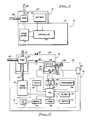
- the infusion system schematically illustrated in Figure 1 has two main components- a main pump unit 10 and a disposable cassette 12.
- the main pump unit 10 includes a prime mover 14 which functions to provide motive power, and a controller portion 16, both of which are mounted in a main pump housing 18.
- the cassette 12 has a pump 20 and a battery 22 mounted within a cassette housing 24.
- the pumping capacity of the pump 20 may vary, according to the rate requirements of the pump 20 for a particular fluid to be pumped. Different cassettes 12 may be manufactured with different capacity pumps 20 for use with a variety of therapeutic fluids.
- a different size battery 22 for different capacity pumps 20 it may be desirable to use a different size battery 22 for different capacity pumps 20. If large quantities of fluid are to be pumped, a larger battery 22 may be required.
- the battery 22 for a high capacity pump 20 may be larger than that shown in the drawings, and the battery 22 could extend down one side of the main pump unit 19, since the cassette 12 is installed at the edge of the main pump unit 10.
- the prime mover 14 may be any of a number of drive mechanisms, including but not limited to an electric motor, a stepper motor, a solenoid apparatus, or a hydraulic motor providing a variable pressure or vacuum.
- the pump 20 will be adapted to be driven by the prime mover 14, as those skilled in the art will appreciate.
- the specific type of prime mover 14 and pump 20 used is not particularly pertinent to the present invention, inasmuch as the present invention may work equally well with any drive/pump scheme.
- the controller 16 operates the prime mover 14 according to programmed instructions, thereby causing the pump 20 to pump specific amounts of therapeutic fluid at specific times. It will be apparent that the present invention as so far described has particular advantages over the art, due to the fact that the pump 20 and the battery 22 are contained in a single disposable cassette 12; a new pump 20 may not be installed without simultaneously installing a new battery 22. This eliminates the possibility of system failure due to medical personnel changing a disposable pump but failing to install new batteries in the device.
- the cassette has the pump 20 at one end and the battery 22 at the other end, with the portions of the cassette 12 in which the pump 20 and the battery 22 are contained fitting into recesses in the main pump unit 10 to help provide a strong attachment between the cassette 12 and the main pump unit 10.
- the cassette 12 may be removably held in place by a connecting screw 30 having a knob 32 at the end of the screw 30 extending from the cassette 12. After placing cassette 12 into position on the main pump unit 10, the screw 30 is turned to fasten the cassette 12 securely to the main pump unit 10.
- cassette 12 may be removably secured to the main pump unit 10.
- plastic clips made as an integral part of the cassette housing 24 may be used, with the plastic clips fitting into mating surfaces (not shown) in the main pump housing 18.
- mating surfaces not shown
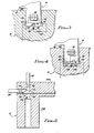
- Pump 20 is illustrated in Figure 5, which has various components mounted between two halves of the cassette housing 24A and 24B.
- the pump 20 illustrated in Figure 5 is one which would be driven by a pneumatic or hydraulic motor (not shown), which would supply alternating air pressure and vacuum.
- Two chambers separated by a diaphragm 42 located between the two halves of the cassette housing 24A and 24B form the working part of the pump 20.
- An upper or pumping chamber 44 in one of the cassette housing halves 24A is the chamber in which the therapeutic fluid will be present.
- the therapeutic fluid enters the pumping chamber 44 through a one-way inlet valve 46 which is supplied with the therapeutic fluid from the inlet 26.
- the one-way inlet valve 46 permits fluid flow only from the inlet 26 into the pumping chamber 44.
- the therapeutic fluid leaves the pumping chamber 44 through a one-way outlet valve 48 which communicates with the outlet 28, through which it will be supplied to a patient.
- the one-way outlet valve 48 likewise permits fluid flow in one direction only, from the pumping chamber 44 to the outlet 28.
- a lower or drive chamber 50 is located in the other half of the cassette housing 24B, on the opposite side of the diaphragm 42 from the pumping chamber 44.
- the drive chamber 50 is supplied with pressure and vacuum from the hydraulic motor (not shown) contained in the main pump unit 10 ( Figure 2).
- An O-ring 52 is located about a channel 54 in the other half of the cassette housing 24B, the O-ring providing a seal between portions of the mechanical drive connection 40 ( Figure 2) connected to the channel 54.
- pump 20 By alternately supplying pressure to the drive chamber 50, fluid will be pumped by the pumping chamber 44 from the inlet 26 to the outlet 28.
- the description of the pump 20 is given by way of example only, and is not intended as a limitation of any kind on the present invention. In fact, a number of different types of pump 30 could be used equally well, such as piston type pumps, rotary pumps, cam actuated pumps, and double acting pumps.
- the electrical connection of the disposable battery 22 contained in the cassette 12 to the controller 16 located in the main pump unit 10 is illustrated.
- the two poles of the battery 22 are connected inside the cassette 12 to two battery terminals 56,58 which are mounted on the outside of the cassette housing 24, on portions of the cassette housing 24 contacting or closely adjacent to the main pump housing 18.
- the battery terminals 56,58 are mounted on a portion of the cassette housing 24 extending into a recess in the main pump unit 10.
- Two corresponding electrical contacts 60,62 are mounted on the exterior of the main pump housing 18, which contacts 60 ,62 will be in electrical communication with the battery terminals 56,58 respectively, when the cassette 12 is mounted onto the main pump unit 10.
- the battery terminals 56, 58 protrude from the cassette housing 24, and the electrical contacts 60,62 are essentially flush with the surface of the main pump housing 18.
- other designs may be used and one variation would be to have a snap type fit or spring loading between the battery terminals 56, 58 and the electrical contacts 60,62 with the snap fit being used to help retain the cassette 12 in position on the main pump unit 10.
- An auxiliary battery 77 typically a long life lithium or similar battery, is used to sustain the memory 74 and the CPU 66 during times when a new cassette 12 is being installed and no main power source is present.
- a low-leakage, high value capacitor may be used instead of the auxiliary battery 77, with such a capacitor being capable of powering the memory 74 for at least a week or so.
- the battery 22 is used to recharge the low-leakage high value capacitor.
- the battery 22 could also be used to recharge the auxiliary battery 77.
- a timer 78 supplies information indicative of various elapsed times to the CPU 66.
- the timer 78 may be started upon installation of the cassette 12 and a fresh battery 22, with a specific time interval embodied in the device as a maximum operating time interval without a cassette change. For example, three days could be set as the maximum operational period without a new cassette 12 being installed. This time period would always include a substantial margin of safety, with the system being assumed to be operating at a maximum operational power draw for the time period. After this time period is reached, the system could be shut down, with no further power being supplied to drive the prime mover 14. At this time, a visual indication could be presented on the display 70, and an audible alarm could be emitted from the alarm 72. Alternatively, the system could drive a display and/or alarm at a central nursing station in a hospital environment.
- the preferred embodiment shown in Figure 2 uses a flip-flop 80 and a three-way switch 82 to perform this function.
- the switch 82 When no cassette 12 is installed, the switch 82 will toggle the reset of the flip-flop 80, to indicate the CPU 66 that the cassette 12 has been removed.
- the switch 82 When a cassette 12 is installed the switch 82 will toggle the set of the flip-flop 80, to cause the timer 78 to begin the three day sequence. It will be realised by those skilled in the art that many alternatives to the described use of the flip-flop 80 exist, all of which are within the scope of the present invention.
- FIGs 3 and 4 Alternative embodiments using an electrical interlock are illustrated in Figures 3 and 4.
- Figure 3 on the bottom of the portion of the cassette 12 containing the battery 22 there is a small, readily breakable link 92 covering a small recess 94.
- a spring 96 which is made of conductive material, is mounted in the portion of the main pump unit 10 receiving the portion of the cassette 12 containing the battery 22 will act to break the link 92, which is made of nonconductive material.
- the link 92 will be forced against the top of the recess 94, insulating the spring from a contact 98 contained in the top of the recess 94.
- FIG 4 Another electrical interlock is illustrated in Figure 4, which again has a breakable link 102 disposed on the bottom of the portion of the cassette 12 containing the battery 22, with the link 102 covering a recess 104. This time, however, the link 102 is made of a conductive material.
- a spring 106 similar to the spring 96 of Figure 3 is again used, with the spring 106 being made of nonconductive or insulated material.
- Two contacts 110, 112 are located in the top of the recess 104, with the contact 110 being attached to the battery 22 and the contact 112 being attached to the battery terminal 58. (The battery terminal 58 is no longer directly connected to the battery 22.)
- the link 102 will close the circuit and operate the system when the cassette 12 is attached to the main pump unit for the first time. When the cassette 12 is removed, the link 102 will no longer be in the recess 104, and the non conductive spring 106 will not complete the circuit. The system will thus not receive any power if the cassette 12 is installed more than once.
- the present invention presents a system having a disposable cassette containing both a pump and a battery.
- the system has an interlock preventing a cassette which is removed from being reinstalled.
- the system further requires that the cassette be changed periodically, otherwise the system is shut down and an alarm is given.
- the result of the integration of the pump and the battery is that both must be periodically changed, and the system thus prevents too long a use of both the disposable pump and the battery, thereby eliminating problems resulting from the use of either for too long.
Abstract
Description
- The present invention relates generally to an electromechanical system for continuously infusing medication into a patient, and more particularly to such a system comprising a fluid pump having an inlet to which the fluid is supplied from a source, and an outlet from which the fluid is pumped, a prime mover for driving the fluid pump and a battery for powering the system.
- In the past there have been two techniques used to deliver drugs which may not be orally ingested to a patient. The first such technique is through an injection, or shot, which delivers a large dosage at relatively infrequent intervals to the patient. This technique is not always satisfactory, particularly when the drug being administered is potentially lethal or has negative side effects when delivered in a large dosage. This problem results in smaller injections being given at more frequent intervals.
- Alternatively, the second technique involves administering a continuous flow of medication to the patient through an IV bottle. Medication may also be delivered through an IV system with an injection being made into a complex maze of IV tubes, hoses, and other paraphernalia. As an alternative to these two techniques of administering medication to a patient, the recent addition of medication infusion pumps has come as a welcome improvement.
- Infusion pumps are used to administer drugs to a patient in small, metered doses at frequent intervals or, alternatively, in the case of some devices, at a slow but essentially continuous rate. Infusion pump therapy may be electronically controlled to deliver precise, metered doses at exactly determined intervals, thereby providing a beneficial gradual infusion of medication to the patient. In this manner, the infusion pump is able to mimic the natural process whereby chemical balances are maintained precisely by operating on a continuous time basis.
- Such infusion pumps typically use as a power source a battery, which is contained inside the housing of the device. Most battery-powered infusion pumps use the battery as the power source for the electrical or electronic components used to control the infusion system in addition to using the battery to power the motor or other apparatus used to pump the medication being infused. It may be desirable to include an auxiliary battery such as a small lithium battery to power memory circuits during times when the main battery is being changed, thereby maintaining operating information stored in the solid state memory of the device.
- In a battery operated infusion pump it may be appreciated that the state of charge of the battery is critical to ensure the continued operation of the device. In a hospital environment a nurse would have to remember to recharge or change the battery in the device periodically, making continued operation of the device absolutely dependent on changing the battery. Since a dead battery would result in the interruption of medication supplied to the patient, most infusion pumps have included some type of alarm to indicate when the battery must be changed. Since safety and reliability of medication infusion pumps are of primary importance, it is essential to have adequate safeguards in the design and operation of the device, and to avoid failure, even for relatively short periods of time.
- An additional requirement has been imposed by the important design consideration of disposability. Since the portion of the device through which medication is pumped must be sterile, in most applications of the infusion equipment some portions of the equipment are used only once and then disposed of, typically at regular intervals such as once daily. It is therefore desirable that the fluid pump portion of the infusion pump device be disposable, and one suitable design might be a fluid pump designed as an attachable cassette which is of inexpensive design, and which is easily installable onto the main pump unit. Any change in pump design must take this disposable nature of the pump portion into account.
- It is an object of the present invention to provide an infusion pump system which is simple in construction and which allows the pump to be readily disposable.
- According to the invention, there is provided a medication infusion system for infusing fluid into a living body, comprising: a fluid pump having an inlet to which the fluid is supplied from a source, and an outlet from which the fluid is pumped, a prime mover for diving the fluid pump, and a battery for powering the system, characterised in that an electronic controller controls the operation of the prime mover to cause the fluid pump to pump precisely metered amounts of fluid at preselected times, the battery powers the prime mover and/or the electronic controller and the battery is attached to and is disposable with the fluid pump.
- There may also be provided means for coupling an output of the prime mover to drive the fluid pump.
- Preferably, the system includes a main pump housing containing the prime mover and the electronic controller in an assembly defining a main pump unit; and a cassette housing containing the disposable fluid pump and battery in an integral package defining a disposable cassette, the disposable cassette being removably attachable to the main pump unit. The cassette housing may be a rigid portion cast or moulded around the battery and pump.
- It is desirable to ensure that the battery used to provide the primary power source for the infusion system be replaced at regular intervals, specifically at the same time the disposable pump cassette is replaced. Attaching the battery to the pump ensures the simultaneous replacement of the pump cassette and the battery and this is a primary advantage of the present invention. The present invention also retains the aseptic nature of the disposable pump cassette while providing for the use of a fresh battery each time a new pump cassette is installed.
- An incidental advantage obtained in tying the replacement of the battery is that the disposal of the pump cassette will therefore be inevitable with the installation of a replacement battery, thereby obviating the possibility of a disposable pump cassette being used beyond the period for which it was designed. The maximum period of use for the pump cassette will therefore be the period defined by the life of the battery. The installation of the pump cassette should therefore preferably involve the use of means to prevent the pump cassette from being reused following its removal from the body of the infusion system after a single use of the cassette.
- The present invention also retains a simple design to minimise the cost of construction of the disposable cassette, and accomplishes all the above objects in a manner which will retain all of the advantages of reliability, durability, and safety of operation. All the advantages of the present invention will result in superior medication infusion system having a number of advantages making the system a highly desirable alternative to systems presently available.
- The system preferably includes connecting means comprising electrical battery terminals located on the disposable cassette and electrical contacts located on the main pump housing arranged to contact the battery terminals when the disposable cassette is attached to the main pump unit. There may be a sliding contact between the battery terminals and the electrical contacts and preferably, the connecting means is usable only once, to prevent reuse of the disposable cassette.
- Preferably, therefore the system includes means for preventing reuse of the disposable cassette after initial detachment from the main pump unit. The means for preventing may comprise a spring loaded switch having a pin biased to extend out of the main pump housing, a notch in a lower corner of the cassette housing; a sloped link which extends at an angle across the notch and which permits the disposable cassette to be inserted past the pin, the angled surface of the sloped link sliding the pin back into the switch; and a bumper protruding from the main pump housing and being arranged to fit within the notch when the disposable cassette is attached to the main pump unit after the pin is slid back into the switch, the bumper either breaking off the sloped link, or bending it back so as to deform it permanently, thereby preventing reinsertion of the disposable cassette, since the pin will hang up in the notch upon reinsertion of the disposable cassette because the sloped link is either broken off or bent back. Preferably, the switch is arranged to detect the presence of the disposable cassette and to cause the system to be reset, and preferably, the preventing means includes means for discharging the battery upon attempted reuse of the disposable cassette in order to disable the system.
- The system may include means for limiting the use of the system in response to the occurrence of specific circumstances, the limiting means comprising, for example means for limiting the time the system will operate after the installation of a new disposable cassette without the replacement of the that cassette, thereby shutting the system down if the disposable cassette is not replaced within a preset maximum time period, or means for preventing further use of the system if the fluid pump has not operated to pump the fluid for a predetermined maximum period of time.
- Preferably, the electronic controller comprises: a CPU for controlling the application of power to the prime mover to cause the fluid to be pumped by the fluid pump; a programmer for setting the various parameters of operation of the system, which parameters are supplied to the CPU; a display for providing a visual indication of information entered through the programmer and for providing information on the operation of the system; a memory for storing information which may be accessed by the CPU; and a long life power source for sustaining the memory and the CPU during times when a new disposable cassette is being installed and no main power source is present.
- The long life power source may be a battery or a low-leakage long life capacitor.
- The system may also include means for monitoring the battery in the disposable cassette and means responsive to the monitoring means arranged to provide an alarm if the level of the battery falls below a first predetermined level, and optionally arranged to cause the system to cease pumping fluid if the level of the battery falls below a second predetermined level which is lower than the first predetermined level.
- Thus, the disadvantages and limitations of the background art discussed above can be overcome by the present invention. With this invention, the disposable pump cassette is constructed integrally with the battery which will furnish the primary power supply for operation of the infusion system. This invention imposes the advantageous requirement that the battery and the fluid pump be simultaneously and periodically replaced. The period of replacement of the pump cassette will be dictated by the life of the battery contained in the cassette, with the cassette being replaced at an interval determined by the life of the battery, the operation of the device, and a substantial margin of safety. The chances of error are reduced since a nurse or other person need no longer remember to change the battery periodically. In addition, the device has an obvious advantage over systems requiring the system to be plugged in to recharge a non-removable battery, in that it is always portable due to the replaceable battery design. Furthermore, the time spent in recharging batteries is also eliminated, resulting in one less step in operating the device, an attractive prospect for use by medical professionals.
- In the preferred embodiment, the fluid pump is mounted in one end of a plastic cassette housing, with the battery being mounted at the other end of the cassette housing. The cassette is snapped into place on the main pump housing, bringing the output of the prime mover into operational contact with the fluid pump. The prime mover may be any of a number of devices, such as a motor having a shaft output, a solenoid, or a hydraulic motor supplying varying pressure or vacuum.
- Snapping the cassette into place may also bring two contacts on exterior of the cassette housing which are connected to the battery into contact with a pair of receiving contacts mounted on the main pump housing, thereby supplying power to the prime mover and associated electronics contained in the main pump housing. Snapping the cassette into place may also cause a safety interlock mechanism to be operated, which will allow a cassette to be inserted into the pump housing only once. This interlock may be of, for example, a mechanical or electrical nature.
- The preferred embodiment also includes a timer feature which is used to ensure that the cassette is replaced prior to battery failure. The device may be disabled after a preset period of time following installation of a new cassette. Another approach of the preferred embodiment is to provide additional checks which are used to disable operation of the device unless a new cassette is installed. If the prime mover does not operate for an extended period, or if battery voltage falls off, the device is disabled. Appropriate alarms or signals may be used to indicate the occurrence of such conditions.
- The present invention therefore represents a solution to the problems discussed above in that a battery is packaged integrally with the disposable fluid pump. A fresh battery is always present when a new cassette is installed, and the cassette and battery are usable only once, therefore preventing the reuse of a cassette which may be contaminated and a battery which may be less than fresh. Tying the battery and fluid pump together also has the benefit of making periodic replacement of the pump mandatory.
- Built-in safeguards prevent the cassette from being used beyond a period in which an acceptable battery level is assured, and also ensure that the device will not be usable after an extended period of disuse. The present invention therefore represents a highly desirably improvement in the art, encompassing the advantages enumerated above with substantially no relative disadvantages.
- According to another aspect of the invention, there is provided a medication infusion system, comprising: a fluid pump having an input to which the fluid is supplied from a source, and an outlet from which the fluid is pumped; a battery for providing electrical power for the system; cassette housing means for containing the fluid pump and battery in an integral package defining a disposable cassette, arranged for removable attachment to a main pump unit, the disposable cassette being disposable after one use; a prime mover for providing a mechanical output to drive the fluid pump; an electronic controller for driving the prime mover; and main pump housing means for containing the prime mover and electronic controller in an assembly defining the main pump unit.
- Such a system preferably also includes means to ensure that the disposable cassette is not reused after detachment from the main pump unit.
- In a preferred form, the invention may comprise a medication infusion system, comprising: a prime mover for providing a mechanical output; an electronic controller for driving the prime mover; main pump housing means for containing the prime mover and the electronic controller in an assembly defining a main pump unit; a disposable fluid pump having an input to which the fluid is supplied from a source, and an outlet from which the fluid is pumped in precisely metered amounts at preselected times; means for coupling the mechanical output of the prime mover to drive the fluid pump: a disposable battery providing electrical power for the prime mover and the controller; cassette housing means for containing the disposable fluid pump and the disposable battery in an integral package defining a disposable cassette, the disposable cassette being arranged for removable attachment to the main pump unit, and being disposable after one use; and means to ensure that the disposable cassette is not reused after initial detachment from the main pump unit.
- The invention also extends to methods of providing a flow of medical fluid to a living body which comprises providing and operating the components of the systems described above.
- The invention may be carried into practice in various ways and some embodiments will now be described by way of example with reference to the accompanying drawings in which:
- Figure 1 is a highly schematic diagram of an infusion system embodying the present invention and illustrating the pump and battery contained in a single disposable cassette;
- Figure 2 is a schematic representation of an implementation of the infusion system of Figure 1 using a mechanical interlock to prevent reuse of the cassette;
- Figure 3 is an alternative embodiment to the mechanical interlock of Figure 2 in which an electrical interlock is used;
- Figure 4 is a further alternative embodiment illustrating a second configuration for an electrical interlock; and
- Figure 5 is a cutaway view of a simple pump driven by pressure or vacuum.
- The infusion system schematically illustrated in Figure 1, has two main components- a
main pump unit 10 and adisposable cassette 12. Themain pump unit 10 includes a prime mover 14 which functions to provide motive power, and acontroller portion 16, both of which are mounted in amain pump housing 18. Thecassette 12 has apump 20 and abattery 22 mounted within acassette housing 24. The pumping capacity of thepump 20 may vary, according to the rate requirements of thepump 20 for a particular fluid to be pumped.Different cassettes 12 may be manufactured with different capacity pumps 20 for use with a variety of therapeutic fluids. - Likewise, it may be desirable to use a
different size battery 22 for different capacity pumps 20. If large quantities of fluid are to be pumped, alarger battery 22 may be required. Thebattery 22 for ahigh capacity pump 20 may be larger than that shown in the drawings, and thebattery 22 could extend down one side of the main pump unit 19, since thecassette 12 is installed at the edge of themain pump unit 10. - When the
cassette 12 is attached to themain pump unit 10, thebattery 22 is connected to furnish electrical power to thecontroller 16 and the prime mover 14, and thepump 20 is placed in position to be driven by the prime mover 14. Thepump 20 has aninlet 26 which is used to supply thepump 20 with a therapeutic fluid from a fluid source (not shown). Likewise, thepump 20 has anoutlet 28 through which the therapeutic fluid is pumped in precisely metered quantities, with fluid leaving thepump 20 through theoutlet 28 being directed eventually to a patient (not shown). - The prime mover 14 may be any of a number of drive mechanisms, including but not limited to an electric motor, a stepper motor, a solenoid apparatus, or a hydraulic motor providing a variable pressure or vacuum. The
pump 20 will be adapted to be driven by the prime mover 14, as those skilled in the art will appreciate. The specific type of prime mover 14 and pump 20 used is not particularly pertinent to the present invention, inasmuch as the present invention may work equally well with any drive/pump scheme. - The
controller 16 operates the prime mover 14 according to programmed instructions, thereby causing thepump 20 to pump specific amounts of therapeutic fluid at specific times. It will be apparent that the present invention as so far described has particular advantages over the art, due to the fact that thepump 20 and thebattery 22 are contained in a singledisposable cassette 12; anew pump 20 may not be installed without simultaneously installing anew battery 22. This eliminates the possibility of system failure due to medical personnel changing a disposable pump but failing to install new batteries in the device. - The use of a
new battery 22 also necessitates the use of anew pump 20, which is an incidental advantage obtained by the system of the present invention. Since thebattery 22 has a relatively well defined lifetime and must be periodically replaced in order for the system to operate, thepump 20 will therefore also be periodically replaced. Other features, and embodiments of the present invention require a more detailed consideration than that carried out with reference to Figure 1 to this point. - Referring now to Figure 2, an example of one possible configuration using the present invention is shown. The cassette has the
pump 20 at one end and thebattery 22 at the other end, with the portions of thecassette 12 in which thepump 20 and thebattery 22 are contained fitting into recesses in themain pump unit 10 to help provide a strong attachment between thecassette 12 and themain pump unit 10. Thecassette 12 may be removably held in place by a connectingscrew 30 having aknob 32 at the end of thescrew 30 extending from thecassette 12. After placingcassette 12 into position on themain pump unit 10, thescrew 30 is turned to fasten thecassette 12 securely to themain pump unit 10. - Of course, those skilled in the art will immediately realise that there are a number of different ways in which the
cassette 12 may be removably secured to themain pump unit 10. For example, plastic clips (not shown) made as an integral part of thecassette housing 24 may be used, with the plastic clips fitting into mating surfaces (not shown) in themain pump housing 18. There are numerous other suitable alternatives. - The
cassette housing 24 holds thepump 20 and thebattery 22 in an integral package, and may do so in various ways. Thecassette housing 24 may be two or more pieces of moulded plastics material, for example, or it may be a rigid portion cast or moulded around thebattery 22 and thepump 20. In nay event, thepump 20 and thebattery 22 are contained in thecassette housing 24 so that thecassette 12 must be removed and disposed of as a unit, thereby making the simultaneous replacement of thepump 20 and the battery 22 a necessity. - This requirement ensures that the
pump 20 and associated portions having contact with the therapeutic fluid will be replaced and afresh battery 22 will be provided each time thecassette 12 is replaced. Both the reliability and the aseptic nature of the infusion system are therefore enhanced. As is apparent, thebattery 22 is a non-rechargeable battery, since thecassette 12 is not to be reused. Since under usual operating circumstances thepump 20 would require replacement before thebattery 22 is exhausted, it is apparent that a reserve of energy representing a substantial margin of safety exists. - In Figure 2, the prime mover 14 is schematically shown to be connected to the
pump 20 by amechanical drive connection 40. These components are shown in a highly schematic form since any of a number of different drive, pump, and connection means may be used without affecting the nature of the present invention. Various drive schemes are well known in the art, and any of these schemes could be adapted for use with the present invention. - One possible type of
pump 20 is illustrated in Figure 5, which has various components mounted between two halves of the cassette housing 24A and 24B. Thepump 20 illustrated in Figure 5 is one which would be driven by a pneumatic or hydraulic motor (not shown), which would supply alternating air pressure and vacuum. Two chambers separated by a diaphragm 42 located between the two halves of the cassette housing 24A and 24B form the working part of thepump 20. - An upper or pumping
chamber 44 in one of the cassette housing halves 24A is the chamber in which the therapeutic fluid will be present. The therapeutic fluid enters the pumpingchamber 44 through a one-way inlet valve 46 which is supplied with the therapeutic fluid from theinlet 26. The one-way inlet valve 46 permits fluid flow only from theinlet 26 into the pumpingchamber 44. The therapeutic fluid leaves the pumpingchamber 44 through a one-way outlet valve 48 which communicates with theoutlet 28, through which it will be supplied to a patient. The one-way outlet valve 48 likewise permits fluid flow in one direction only, from the pumpingchamber 44 to theoutlet 28. - A lower or drive
chamber 50 is located in the other half of the cassette housing 24B, on the opposite side of the diaphragm 42 from the pumpingchamber 44. Thedrive chamber 50 is supplied with pressure and vacuum from the hydraulic motor (not shown) contained in the main pump unit 10 (Figure 2). An O-ring 52 is located about achannel 54 in the other half of the cassette housing 24B, the O-ring providing a seal between portions of the mechanical drive connection 40 (Figure 2) connected to thechannel 54. - By alternately supplying pressure to the
drive chamber 50, fluid will be pumped by the pumpingchamber 44 from theinlet 26 to theoutlet 28. The description of thepump 20 is given by way of example only, and is not intended as a limitation of any kind on the present invention. In fact, a number of different types ofpump 30 could be used equally well, such as piston type pumps, rotary pumps, cam actuated pumps, and double acting pumps. - Referring again to Figure 2, the electrical connection of the
disposable battery 22 contained in thecassette 12 to thecontroller 16 located in themain pump unit 10 is illustrated. The two poles of thebattery 22 are connected inside thecassette 12 to twobattery terminals cassette housing 24, on portions of thecassette housing 24 contacting or closely adjacent to themain pump housing 18. In the embodiment illustrated in Figure 2, thebattery terminals cassette housing 24 extending into a recess in themain pump unit 10. - Two corresponding
electrical contacts main pump housing 18, whichcontacts battery terminals cassette 12 is mounted onto themain pump unit 10. In the preferred embodiment illustrated in Figure 2, thebattery terminals cassette housing 24, and theelectrical contacts main pump housing 18. Of course other designs may be used and one variation would be to have a snap type fit or spring loading between thebattery terminals electrical contacts cassette 12 in position on themain pump unit 10. - Electrical power is thus supplied from the
battery 22 to thecontroller 16, with aswitch 64 typically being included in the electrical path between thebattery 22 and thecontroller 16. Thecontroller 16 has several components which are likely to be included and which are illustrated schematically in Figure 2, with a central processing unit (CPU) 66 representing the heart of any electronic design for thecontroller 16. TheCPU 66 will control the application of power to the prime mover 14 to cause the therapeutic fluid to be pumped at specific selected rates or in specific amounts and at specific selected times. - A
programmer 68 is used to set or enter the various parameters of operation of the system, which parameters are supplied to theCPU 66. Theprogrammer 68 may be a keyboard or other manual input device, or may include, either alternatively or in addition to the manual input device, receiving facilities for obtaining programming information from an external programming unit (not shown). Typical information entered through the programmer may include various times for various operations to take Place, the rate of operations (which would set pump rate, and the lengths of such operations. - A
display 70 which receives output signals from theCPU 66 may be provided to provide a visual indication of information entered through theprogrammer 68. Thedisplay 70 may also be used to provide information on the operation of the system during operation, in which case thedisplay 70 would be of a low power type, such as an LCD display. Anaudible alarm 72 may also be used to indicate successful entry of information, errors in entering the information, etc. TheCPU 66 is able to store and access information from amemory 74, and is supplied with signals from aclock 76. Thememory 74 may also be reset through theprogrammer 68 for use with a new patient, but will be preserved for the same patient even when the device is reprogrammed for different medications, rates, or times. - An auxiliary battery 77, typically a long life lithium or similar battery, is used to sustain the
memory 74 and theCPU 66 during times when anew cassette 12 is being installed and no main power source is present. Alternately, a low-leakage, high value capacitor may be used instead of the auxiliary battery 77, with such a capacitor being capable of powering thememory 74 for at least a week or so. In this case, thebattery 22 is used to recharge the low-leakage high value capacitor. Thebattery 22 could also be used to recharge the auxiliary battery 77. Atimer 78 supplies information indicative of various elapsed times to theCPU 66. - The
timer 78 may be started upon installation of thecassette 12 and afresh battery 22, with a specific time interval embodied in the device as a maximum operating time interval without a cassette change. For example, three days could be set as the maximum operational period without anew cassette 12 being installed. This time period would always include a substantial margin of safety, with the system being assumed to be operating at a maximum operational power draw for the time period. After this time period is reached, the system could be shut down, with no further power being supplied to drive the prime mover 14. At this time, a visual indication could be presented on thedisplay 70, and an audible alarm could be emitted from thealarm 72. Alternatively, the system could drive a display and/or alarm at a central nursing station in a hospital environment. - Another approach to the shutdown of the system when the
battery 22 is not replaced is the monitoring of the voltage produced by thebattery 22. When thebattery 22 voltage falls to a predetermined level, thealarm 72 is sounded. When thebattery 22 voltage falls to a second lower predetermined level, the system is show down, with thebattery 22 being used only to help maintain thememory 74. - An additional feature which may be included in the system is the incorporation of a system shutdown for other reasons, such as a system failure or the absence of operation of the prime mover 14 over a shorter period of time, such as a two day period. Under such circumstances, the
controller 16 would be disabled until anew cassette 12 is installed. - While the timing operations could be controlled by the use of an initial startup sequence at which time the
timer 78 is reset and started, the preferred embodiment shown in Figure 2 uses a flip-flop 80 and a three-way switch 82 to perform this function. When nocassette 12 is installed, theswitch 82 will toggle the reset of the flip-flop 80, to indicate theCPU 66 that thecassette 12 has been removed. When acassette 12 is installed theswitch 82 will toggle the set of the flip-flop 80, to cause thetimer 78 to begin the three day sequence. It will be realised by those skilled in the art that many alternatives to the described use of the flip-flop 80 exist, all of which are within the scope of the present invention. - Finally, another aspect which may be incorporated into the present invention involves the use of an interlock to prevent reuse of a
cassette 12. In a hospital, when trained professionals are maintaining the system, the need for such an interlock may be minimal, but for home use of the system such an interlock is highly desirable. Interlocks may be either electrical or mechanical, and a mechanical interlock is illustrated in Figure 2. This interlock uses theswitch 82, which is spring loaded to bias thepin 84 of theswitch 82 to extend out of themain pump housing 18. Thecassette housing 24 has a lower corner with anotch 86 having a slopedlink 88 extending at an angle across thenotch 86. The slopedlink 88 permits thecassette 12 to be inserted past thepin 84, with the angled surface of the slopedlink 88 sliding thepin 84 back into theswitch 82. - After the
pin 84 is pushed in and thecassette 12 is lowered further towards its position on themain pump unit 10, the slopedlink 88 will be met by abumper 90 protruding from themain pump housing 18 and sized to fit within thenotch 86 when thecassette 12 is attached to themain pump unit 10. Thebumper 90 will break off the slopedlink 88, or alternatively bend it back so as to deform it permanently. It is thus apparent that if thecassette 12 is removed from themain pump unit 10, it will not be able to be replaced since thepin 84 of theswitch 82 will catch in thenotch 86, since the slopedlink 88 is either broken off or bent back. After acassette 12 has been removed, it will therefore be necessary to use anew cassette 12. - Alternative embodiments using an electrical interlock are illustrated in Figures 3 and 4. In Figure 3, on the bottom of the portion of the
cassette 12 containing thebattery 22 there is a small, readilybreakable link 92 covering asmall recess 94. Aspring 96, which is made of conductive material, is mounted in the portion of themain pump unit 10 receiving the portion of thecassette 12 containing thebattery 22 will act to break thelink 92, which is made of nonconductive material. Thelink 92 will be forced against the top of therecess 94, insulating the spring from acontact 98 contained in the top of therecess 94. - If a
cassette 12 is removed and subsequently reinstalled, thelink 92 will no longer remain to insulate thespring 96, which will then touch thecontact 98. This completes a circuit including aresistor 100 connected between thespring 96 and theelectrical contact 58, and so thebattery 22 will discharge. The reuse of thecassette 12 is thereby effectively prevented. Theresistor 100 is small enough to discharge thebattery 22 relatively quickly, but large enough to prevent overheating caused by the discharging and to have adequate heat dissipating capacity. - Another electrical interlock is illustrated in Figure 4, which again has a breakable link 102 disposed on the bottom of the portion of the
cassette 12 containing thebattery 22, with the link 102 covering a recess 104. This time, however, the link 102 is made of a conductive material. A spring 106 similar to thespring 96 of Figure 3 is again used, with the spring 106 being made of nonconductive or insulated material. A small wedge 108 mounted on themain pump unit 10 next to the spring 106, breaks the link 102 as thecassette 10 is attached to themain pump unit 10, and the spring 106 forces the link 102 against the top of the recess 104. - Two contacts 110, 112 are located in the top of the recess 104, with the contact 110 being attached to the
battery 22 and the contact 112 being attached to thebattery terminal 58. (Thebattery terminal 58 is no longer directly connected to thebattery 22.) The link 102 will close the circuit and operate the system when thecassette 12 is attached to the main pump unit for the first time. When thecassette 12 is removed, the link 102 will no longer be in the recess 104, and the non conductive spring 106 will not complete the circuit. The system will thus not receive any power if thecassette 12 is installed more than once. - It may therefore be appreciated that the present invention presents a system having a disposable cassette containing both a pump and a battery. The system has an interlock preventing a cassette which is removed from being reinstalled. The system further requires that the cassette be changed periodically, otherwise the system is shut down and an alarm is given. The result of the integration of the pump and the battery is that both must be periodically changed, and the system thus prevents too long a use of both the disposable pump and the battery, thereby eliminating problems resulting from the use of either for too long.
Claims (11)
Applications Claiming Priority (2)
| Application Number | Priority Date | Filing Date | Title |
|---|---|---|---|
| US4352 | 1987-01-16 | ||
| US07/004,352 US4808167A (en) | 1987-01-16 | 1987-01-16 | Medication infusion system with disposable pump/battery cassette |
Publications (3)
| Publication Number | Publication Date |
|---|---|
| EP0275213A2 true EP0275213A2 (en) | 1988-07-20 |
| EP0275213A3 EP0275213A3 (en) | 1989-03-22 |
| EP0275213B1 EP0275213B1 (en) | 1992-03-18 |
Family
ID=21710351
Family Applications (1)
| Application Number | Title | Priority Date | Filing Date |
|---|---|---|---|
| EP88300340A Expired - Lifetime EP0275213B1 (en) | 1987-01-16 | 1988-01-15 | Medication infusion system |
Country Status (5)
| Country | Link |
|---|---|
| US (1) | US4808167A (en) |
| EP (1) | EP0275213B1 (en) |
| JP (1) | JPS63272359A (en) |
| CA (1) | CA1324299C (en) |
| DE (1) | DE3869142D1 (en) |
Cited By (37)
| Publication number | Priority date | Publication date | Assignee | Title |
|---|---|---|---|---|
| EP0319279A1 (en) * | 1987-12-01 | 1989-06-07 | PACESETTER INFUSION LTD. trading as MINIMED TECHNOLOGIES | Cassette loading and latching apparatus for a medication infusion system |
| EP0379792A2 (en) * | 1989-01-26 | 1990-08-01 | Graymills Corporation | Disposable pump assembly |
| EP0447909A1 (en) * | 1990-03-23 | 1991-09-25 | Asulab S.A. | Portable pump for the administration of therapeutic liquids |
| EP0467766A1 (en) * | 1990-07-18 | 1992-01-22 | LABORATOIRES DEGLAUDE (Sociéte anonyme) | Electrostimulation apparatus |
| WO1992018175A1 (en) * | 1991-04-18 | 1992-10-29 | Novo Nordisk A/S | Infuser |
| EP0521184A1 (en) * | 1991-07-05 | 1993-01-07 | Asulab S.A. | Portable pump for the administration of therapeutic liquids |
| US5984894A (en) * | 1991-04-18 | 1999-11-16 | Novo Nordisk A/S | Infuser |
| WO2003059419A3 (en) * | 2002-01-07 | 2003-11-06 | Baxter Int | Medical infusion system with integrated power supply and pump therefor |
| EP1381408A2 (en) * | 2001-02-22 | 2004-01-21 | Insulet Corporation | Modular infusion device and method |
| WO2008144697A1 (en) * | 2007-05-21 | 2008-11-27 | M2 Group Holdings, Inc. | Removable controller for an infusion pump |
| WO2009035753A2 (en) * | 2007-09-07 | 2009-03-19 | M2 Group Holdings, Inc. | Power management techniques for an infusion pump system |
| US7938797B2 (en) | 2008-05-05 | 2011-05-10 | Asante Solutions, Inc. | Infusion pump system |
| US7959598B2 (en) | 2008-08-20 | 2011-06-14 | Asante Solutions, Inc. | Infusion pump systems and methods |
| US8287487B2 (en) | 2008-10-15 | 2012-10-16 | Asante Solutions, Inc. | Infusion pump system and methods |
| WO2014015239A1 (en) * | 2012-07-19 | 2014-01-23 | Asante Solutions, Inc. | Infusion pump system and method |
| US20140276431A1 (en) * | 2005-09-26 | 2014-09-18 | Asante Solutions, Inc. | Operating an Infusion Pump System |
| US8974439B2 (en) | 2009-01-02 | 2015-03-10 | Asante Solutions, Inc. | Infusion pump system and methods |
| US9610404B2 (en) | 2011-09-07 | 2017-04-04 | Bigfoot Biomedical, Inc. | Method for occlusion detection for an infusion pump system |
| US9629901B2 (en) | 2014-07-01 | 2017-04-25 | Bigfoot Biomedical, Inc. | Glucagon administration system and methods |
| US9717849B2 (en) | 2007-05-21 | 2017-08-01 | Bigfoot Biomedical, Inc. | Occlusion sensing for an infusion pump |
| US9878097B2 (en) | 2015-04-29 | 2018-01-30 | Bigfoot Biomedical, Inc. | Operating an infusion pump system |
| US9901677B2 (en) | 2012-10-16 | 2018-02-27 | Bigfoot Biomedical, Inc. | Infusion pump system and methods |
| US9919096B2 (en) | 2014-08-26 | 2018-03-20 | Bigfoot Biomedical, Inc. | Infusion pump system and method |
| US9956339B2 (en) | 2013-06-03 | 2018-05-01 | Bigfoot Biomedical, Inc. | Infusion pump system and method |
| US10064993B2 (en) | 2005-09-26 | 2018-09-04 | Bigfoot Biomedical, Inc. | Dispensing fluid from an infusion pump system |
| US10137246B2 (en) | 2014-08-06 | 2018-11-27 | Bigfoot Biomedical, Inc. | Infusion pump assembly and method |
| USD836769S1 (en) | 2016-12-12 | 2018-12-25 | Bigfoot Biomedical, Inc. | Insulin delivery controller |
| USD839294S1 (en) | 2017-06-16 | 2019-01-29 | Bigfoot Biomedical, Inc. | Display screen with graphical user interface for closed-loop medication delivery |
| US10426896B2 (en) | 2016-09-27 | 2019-10-01 | Bigfoot Biomedical, Inc. | Medicine injection and disease management systems, devices, and methods |
| US10449294B1 (en) | 2016-01-05 | 2019-10-22 | Bigfoot Biomedical, Inc. | Operating an infusion pump system |
| US10569015B2 (en) | 2013-12-02 | 2020-02-25 | Bigfoot Biomedical, Inc. | Infusion pump system and method |
| US10987468B2 (en) | 2016-01-05 | 2021-04-27 | Bigfoot Biomedical, Inc. | Operating multi-modal medicine delivery systems |
| US11096624B2 (en) | 2016-12-12 | 2021-08-24 | Bigfoot Biomedical, Inc. | Alarms and alerts for medication delivery devices and systems |
| US11147914B2 (en) | 2013-07-19 | 2021-10-19 | Bigfoot Biomedical, Inc. | Infusion pump system and method |
| US11389088B2 (en) | 2017-07-13 | 2022-07-19 | Bigfoot Biomedical, Inc. | Multi-scale display of blood glucose information |
| WO2023014717A1 (en) * | 2021-08-03 | 2023-02-09 | Boston Scientific Scimed, Inc. | Lockout mechanism for a single use device |
| CN117357182A (en) * | 2023-12-06 | 2024-01-09 | 微至(苏州)医疗科技有限公司 | Electric anastomat |
Families Citing this family (89)
| Publication number | Priority date | Publication date | Assignee | Title |
|---|---|---|---|---|
| US5935099A (en) | 1992-09-09 | 1999-08-10 | Sims Deltec, Inc. | Drug pump systems and methods |
| US6241704B1 (en) * | 1901-11-22 | 2001-06-05 | Sims Deltec, Inc. | Drug pump systems and methods |
| US4878896A (en) * | 1987-12-01 | 1989-11-07 | Pacesetter Infusion, Ltd. | Cassette optical identification apparatus for a medication infusion system |
| US5019041A (en) * | 1988-03-08 | 1991-05-28 | Scimed Life Systems, Inc. | Balloon catheter inflation device |
| US4930495A (en) * | 1988-12-09 | 1990-06-05 | The Upsher Laryngoscope Corporation | Laryngoscope including a disposable blade and its method of use |
| US4950134A (en) * | 1988-12-27 | 1990-08-21 | Cybor Corporation | Precision liquid dispenser |
| US5149322A (en) * | 1991-01-14 | 1992-09-22 | Kensey Nash Corporation | Motor driven apparatus having means to prevent reuse and method of use of said apparatus |
| US5250027A (en) * | 1991-10-08 | 1993-10-05 | Sherwood Medical Company | Peristaltic infusion device with backpack sensor |
| EP0655107B1 (en) * | 1992-06-09 | 2002-10-16 | Baxter International Inc. | Programmable infusion pump with interchangeable tubing |
| US5490765A (en) * | 1993-05-17 | 1996-02-13 | Cybor Corporation | Dual stage pump system with pre-stressed diaphragms and reservoir |
| US5531697A (en) * | 1994-04-15 | 1996-07-02 | Sims Deltec, Inc. | Systems and methods for cassette identification for drug pumps |
| US5609575A (en) * | 1994-04-11 | 1997-03-11 | Graseby Medical Limited | Infusion pump and method with dose-rate calculation |
| JP3920326B2 (en) * | 1994-04-15 | 2007-05-30 | アレゲーニー・シンガー リサーチ インスティチュート | Blood pump device |
| US5637093A (en) * | 1995-03-06 | 1997-06-10 | Sabratek Corporation | Infusion pump with selective backlight |
| US5795327A (en) * | 1995-03-06 | 1998-08-18 | Sabratek Corporation | Infusion pump with historical data recording |
| US5628619A (en) * | 1995-03-06 | 1997-05-13 | Sabratek Corporation | Infusion pump having power-saving modes |
| US5904668A (en) * | 1995-03-06 | 1999-05-18 | Sabratek Corporation | Cassette for an infusion pump |
| US5620312A (en) * | 1995-03-06 | 1997-04-15 | Sabratek Corporation | Infusion pump with dual-latching mechanism |
| US6328712B1 (en) * | 1996-02-28 | 2001-12-11 | Smisson-Cartledge Biomedical Corporation | Rapid infusion system |
| US5853386A (en) * | 1996-07-25 | 1998-12-29 | Alaris Medical Systems, Inc. | Infusion device with disposable elements |
| US6852090B2 (en) * | 1997-02-14 | 2005-02-08 | Nxstage Medical, Inc. | Fluid processing systems and methods using extracorporeal fluid flow panels oriented within a cartridge |
| US7776014B2 (en) * | 1998-01-29 | 2010-08-17 | Peter Visconti | Disposable surgical suction/irrigation trumpet valve tube cassette |
| US6468242B1 (en) | 1998-03-06 | 2002-10-22 | Baxter International Inc. | Medical apparatus with patient data recording |
| US6358237B1 (en) | 1999-01-19 | 2002-03-19 | Assistive Technology Products, Inc. | Methods and apparatus for delivering fluids to a patient |
| US6554791B1 (en) * | 1999-09-29 | 2003-04-29 | Smisson-Cartledge Biomedical, Llc | Rapid infusion system |
| US7780619B2 (en) * | 1999-11-29 | 2010-08-24 | Nxstage Medical, Inc. | Blood treatment apparatus |
| DE60125806T2 (en) * | 2000-09-22 | 2007-10-11 | C.R. Bard, Inc. | SURGICAL DISHWASHER |
| US7771379B2 (en) * | 2001-05-24 | 2010-08-10 | Nxstage Medical, Inc. | Functional isolation of upgradeable components to reduce risk in medical treatment devices |
| US8250483B2 (en) * | 2002-02-28 | 2012-08-21 | Smiths Medical Asd, Inc. | Programmable medical infusion pump displaying a banner |
| US8504179B2 (en) * | 2002-02-28 | 2013-08-06 | Smiths Medical Asd, Inc. | Programmable medical infusion pump |
| CN1668358A (en) * | 2002-05-16 | 2005-09-14 | 斯科特实验室公司 | Kits of medical supplies for sedation and analgesia |
| ES2737835T3 (en) * | 2003-04-23 | 2020-01-16 | Valeritas Inc | Hydraulically driven pump for long-term medication administration |
| US8954336B2 (en) * | 2004-02-23 | 2015-02-10 | Smiths Medical Asd, Inc. | Server for medical device |
| US7758491B2 (en) * | 2004-04-05 | 2010-07-20 | Genesee Biomedical, Inc. | Method and apparatus for the surgical treatment of congestive heart failure |
| WO2006014425A1 (en) | 2004-07-02 | 2006-02-09 | Biovalve Technologies, Inc. | Methods and devices for delivering glp-1 and uses thereof |
| US7775966B2 (en) | 2005-02-24 | 2010-08-17 | Ethicon Endo-Surgery, Inc. | Non-invasive pressure measurement in a fluid adjustable restrictive device |
| US7699770B2 (en) | 2005-02-24 | 2010-04-20 | Ethicon Endo-Surgery, Inc. | Device for non-invasive measurement of fluid pressure in an adjustable restriction device |
| US8066629B2 (en) | 2005-02-24 | 2011-11-29 | Ethicon Endo-Surgery, Inc. | Apparatus for adjustment and sensing of gastric band pressure |
| US7658196B2 (en) | 2005-02-24 | 2010-02-09 | Ethicon Endo-Surgery, Inc. | System and method for determining implanted device orientation |
| US7927270B2 (en) | 2005-02-24 | 2011-04-19 | Ethicon Endo-Surgery, Inc. | External mechanical pressure sensor for gastric band pressure measurements |
| US7775215B2 (en) | 2005-02-24 | 2010-08-17 | Ethicon Endo-Surgery, Inc. | System and method for determining implanted device positioning and obtaining pressure data |
| US8016744B2 (en) | 2005-02-24 | 2011-09-13 | Ethicon Endo-Surgery, Inc. | External pressure-based gastric band adjustment system and method |
| US7975491B2 (en) * | 2005-03-17 | 2011-07-12 | Smisson-Cartledge Biomedical Llc | Heat exchange system for a pump device |
| US7563248B2 (en) * | 2005-03-17 | 2009-07-21 | Smisson-Cartledge Biomedical Llc | Infusion fluid heat exchanger and cartridge |
| AU2007233231B2 (en) * | 2006-03-30 | 2011-02-24 | Mannkind Corporation | Multi-cartridge fluid delivery device |
| EP1839695A1 (en) * | 2006-03-31 | 2007-10-03 | Debiotech S.A. | Medical liquid injection device |
| US8152710B2 (en) | 2006-04-06 | 2012-04-10 | Ethicon Endo-Surgery, Inc. | Physiological parameter analysis for an implantable restriction device and a data logger |
| US8870742B2 (en) | 2006-04-06 | 2014-10-28 | Ethicon Endo-Surgery, Inc. | GUI for an implantable restriction device and a data logger |
| US8057464B2 (en) * | 2006-05-03 | 2011-11-15 | Light Sciences Oncology, Inc. | Light transmission system for photoreactive therapy |
| US20080126969A1 (en) * | 2006-08-03 | 2008-05-29 | Blomquist Michael L | Interface for medical infusion pump |
| US8858526B2 (en) * | 2006-08-03 | 2014-10-14 | Smiths Medical Asd, Inc. | Interface for medical infusion pump |
| US8965707B2 (en) | 2006-08-03 | 2015-02-24 | Smiths Medical Asd, Inc. | Interface for medical infusion pump |
| US8435206B2 (en) * | 2006-08-03 | 2013-05-07 | Smiths Medical Asd, Inc. | Interface for medical infusion pump |
| US8149131B2 (en) | 2006-08-03 | 2012-04-03 | Smiths Medical Asd, Inc. | Interface for medical infusion pump |
| US7833196B2 (en) | 2007-05-21 | 2010-11-16 | Asante Solutions, Inc. | Illumination instrument for an infusion pump |
| US7794426B2 (en) | 2007-05-21 | 2010-09-14 | Asante Solutions, Inc. | Infusion pump system with contamination-resistant features |
| US8187163B2 (en) | 2007-12-10 | 2012-05-29 | Ethicon Endo-Surgery, Inc. | Methods for implanting a gastric restriction device |
| US8100870B2 (en) | 2007-12-14 | 2012-01-24 | Ethicon Endo-Surgery, Inc. | Adjustable height gastric restriction devices and methods |
| US8377079B2 (en) | 2007-12-27 | 2013-02-19 | Ethicon Endo-Surgery, Inc. | Constant force mechanisms for regulating restriction devices |
| US8142452B2 (en) | 2007-12-27 | 2012-03-27 | Ethicon Endo-Surgery, Inc. | Controlling pressure in adjustable restriction devices |
| US8986253B2 (en) | 2008-01-25 | 2015-03-24 | Tandem Diabetes Care, Inc. | Two chamber pumps and related methods |
| US8591395B2 (en) | 2008-01-28 | 2013-11-26 | Ethicon Endo-Surgery, Inc. | Gastric restriction device data handling devices and methods |
| US8337389B2 (en) | 2008-01-28 | 2012-12-25 | Ethicon Endo-Surgery, Inc. | Methods and devices for diagnosing performance of a gastric restriction system |
| US8192350B2 (en) | 2008-01-28 | 2012-06-05 | Ethicon Endo-Surgery, Inc. | Methods and devices for measuring impedance in a gastric restriction system |
| US7844342B2 (en) | 2008-02-07 | 2010-11-30 | Ethicon Endo-Surgery, Inc. | Powering implantable restriction systems using light |
| US8221439B2 (en) | 2008-02-07 | 2012-07-17 | Ethicon Endo-Surgery, Inc. | Powering implantable restriction systems using kinetic motion |
| US8114345B2 (en) | 2008-02-08 | 2012-02-14 | Ethicon Endo-Surgery, Inc. | System and method of sterilizing an implantable medical device |
| US8591532B2 (en) | 2008-02-12 | 2013-11-26 | Ethicon Endo-Sugery, Inc. | Automatically adjusting band system |
| US8057492B2 (en) | 2008-02-12 | 2011-11-15 | Ethicon Endo-Surgery, Inc. | Automatically adjusting band system with MEMS pump |
| US8034065B2 (en) | 2008-02-26 | 2011-10-11 | Ethicon Endo-Surgery, Inc. | Controlling pressure in adjustable restriction devices |
| US8187162B2 (en) | 2008-03-06 | 2012-05-29 | Ethicon Endo-Surgery, Inc. | Reorientation port |
| US8233995B2 (en) | 2008-03-06 | 2012-07-31 | Ethicon Endo-Surgery, Inc. | System and method of aligning an implantable antenna |
| US8133197B2 (en) | 2008-05-02 | 2012-03-13 | Smiths Medical Asd, Inc. | Display for pump |
| CA2724635A1 (en) * | 2008-05-19 | 2009-11-26 | Tandem Diabetes Care, Inc. | Disposable pump reservoir and related methods |
| AU2010278894B2 (en) | 2009-07-30 | 2014-01-30 | Tandem Diabetes Care, Inc. | Infusion pump system with disposable cartridge having pressure venting and pressure feedback |
| USD669165S1 (en) | 2010-05-27 | 2012-10-16 | Asante Solutions, Inc. | Infusion pump |
| US8936447B2 (en) * | 2010-08-26 | 2015-01-20 | Carefusion 303, Inc. | IV pump dual piston disposable cassette and system |
| US8852152B2 (en) | 2011-02-09 | 2014-10-07 | Asante Solutions, Inc. | Infusion pump systems and methods |
| US9180242B2 (en) | 2012-05-17 | 2015-11-10 | Tandem Diabetes Care, Inc. | Methods and devices for multiple fluid transfer |
| US20130310738A1 (en) * | 2012-05-21 | 2013-11-21 | Lifemedix, Llc | Portable intravenous fluid delivery device with a user interface |
| US9555186B2 (en) | 2012-06-05 | 2017-01-31 | Tandem Diabetes Care, Inc. | Infusion pump system with disposable cartridge having pressure venting and pressure feedback |
| US8454562B1 (en) | 2012-07-20 | 2013-06-04 | Asante Solutions, Inc. | Infusion pump system and method |
| CA2896100C (en) | 2013-01-28 | 2021-04-27 | Smiths Medical Asd, Inc. | Medication safety devices and methods |
| US9173998B2 (en) | 2013-03-14 | 2015-11-03 | Tandem Diabetes Care, Inc. | System and method for detecting occlusions in an infusion pump |
| US20140276042A1 (en) * | 2013-03-15 | 2014-09-18 | Syntheon, Llc | Integrated catheter and powered injector system for use in performing radial angiography |
| US9180243B2 (en) | 2013-03-15 | 2015-11-10 | Tandem Diabetes Care, Inc. | Detection of infusion pump conditions |
| US20160058940A1 (en) | 2014-08-28 | 2016-03-03 | Zyno Medical, LLC. | Low-cost ambulatory medical pump |
| US10363111B2 (en) * | 2016-02-05 | 2019-07-30 | Johnson & Johnson Surgical Vision, Inc. | Phacoemulsification surgical multi-use pack usage tracker system |
| USD809134S1 (en) | 2016-03-10 | 2018-01-30 | Bigfoot Biomedical, Inc. | Infusion pump assembly |
Citations (5)
| Publication number | Priority date | Publication date | Assignee | Title |
|---|---|---|---|---|
| US3985133A (en) * | 1974-05-28 | 1976-10-12 | Imed Corporation | IV pump |
| GB2009453A (en) * | 1977-12-02 | 1979-06-13 | Baxter Travenol Lab | Fluid infusion apparatus |
| GB2120003A (en) * | 1982-04-30 | 1983-11-23 | Robin Bransbury | Improvements in battery-powered equipment |
| EP0110276A2 (en) * | 1982-12-06 | 1984-06-13 | Abbott Laboratories | Infusion pump system |
| WO1985000523A1 (en) * | 1983-07-18 | 1985-02-14 | Baxter Travenol Laboratories, Inc. | Solution container having integral power source |
Family Cites Families (11)
| Publication number | Priority date | Publication date | Assignee | Title |
|---|---|---|---|---|
| US3252623A (en) * | 1965-07-22 | 1966-05-24 | C F Liquidation Corp | Apparatus for monitoring dispensing of liquid |
| US3543662A (en) * | 1968-10-10 | 1970-12-01 | Polaroid Corp | Film cassette including battery power supply |
| US4074295A (en) * | 1976-04-23 | 1978-02-14 | Polaroid Corporation | Compact accessory strobe for cameras with battery enclosed film pack |
| US4142524A (en) * | 1977-06-02 | 1979-03-06 | Andros Incorporated | Cassette for intravenous delivery system |
| US4256437A (en) * | 1978-02-01 | 1981-03-17 | Stewart Naumann Laboratories, Inc. | Peristaltic infusion pump and method |
| US4266545A (en) * | 1979-04-06 | 1981-05-12 | Moss James P | Portable suction device for collecting fluids from a closed wound |
| US4336800A (en) * | 1980-08-01 | 1982-06-29 | Oximetrix, Inc. | Intravenous metering device |
| US4324473A (en) * | 1980-10-03 | 1982-04-13 | Polaroid Corporation | SX-70 Film pack with battery hold down structure |
| US4396385A (en) * | 1980-12-05 | 1983-08-02 | Baxter Travenol Laboratories, Inc. | Flow metering apparatus for a fluid infusion system |
| DE3408331C2 (en) * | 1984-03-07 | 1986-06-12 | Fresenius AG, 6380 Bad Homburg | Pumping arrangement for medical purposes |
| US4557725A (en) * | 1984-05-04 | 1985-12-10 | Oximetrix, Inc. | I. V. Pump cassette |
-
1987
- 1987-01-16 US US07/004,352 patent/US4808167A/en not_active Expired - Lifetime
- 1987-12-03 CA CA000553423A patent/CA1324299C/en not_active Expired - Lifetime
-
1988
- 1988-01-15 EP EP88300340A patent/EP0275213B1/en not_active Expired - Lifetime
- 1988-01-15 DE DE8888300340T patent/DE3869142D1/en not_active Expired - Fee Related
- 1988-01-16 JP JP63007375A patent/JPS63272359A/en active Pending
Patent Citations (5)
| Publication number | Priority date | Publication date | Assignee | Title |
|---|---|---|---|---|
| US3985133A (en) * | 1974-05-28 | 1976-10-12 | Imed Corporation | IV pump |
| GB2009453A (en) * | 1977-12-02 | 1979-06-13 | Baxter Travenol Lab | Fluid infusion apparatus |
| GB2120003A (en) * | 1982-04-30 | 1983-11-23 | Robin Bransbury | Improvements in battery-powered equipment |
| EP0110276A2 (en) * | 1982-12-06 | 1984-06-13 | Abbott Laboratories | Infusion pump system |
| WO1985000523A1 (en) * | 1983-07-18 | 1985-02-14 | Baxter Travenol Laboratories, Inc. | Solution container having integral power source |
Cited By (68)
| Publication number | Priority date | Publication date | Assignee | Title |
|---|---|---|---|---|
| EP0319279A1 (en) * | 1987-12-01 | 1989-06-07 | PACESETTER INFUSION LTD. trading as MINIMED TECHNOLOGIES | Cassette loading and latching apparatus for a medication infusion system |
| EP0379792A2 (en) * | 1989-01-26 | 1990-08-01 | Graymills Corporation | Disposable pump assembly |
| EP0379792A3 (en) * | 1989-01-26 | 1990-10-03 | Graymills Corporation | Disposable pump assembly |
| US5266013A (en) * | 1990-03-23 | 1993-11-30 | Asulab S.A. | Portable pump for the administration of a therapeutic |
| EP0447909A1 (en) * | 1990-03-23 | 1991-09-25 | Asulab S.A. | Portable pump for the administration of therapeutic liquids |
| FR2659856A1 (en) * | 1990-03-23 | 1991-09-27 | Asulab Sa | PORTABLE PUMP FOR ADMINISTERING A LIQUID THERAPEUTIC SUBSTANCE. |
| FR2664818A1 (en) * | 1990-07-18 | 1992-01-24 | Deglaude Lab Sa | ELECTRO-STIMULATION APPARATUS. |
| US5218960A (en) * | 1990-07-18 | 1993-06-15 | Laboratoires Deglaude | Electro-stimulation apparatus |
| EP0467766A1 (en) * | 1990-07-18 | 1992-01-22 | LABORATOIRES DEGLAUDE (Sociéte anonyme) | Electrostimulation apparatus |
| WO1992018175A1 (en) * | 1991-04-18 | 1992-10-29 | Novo Nordisk A/S | Infuser |
| US5984894A (en) * | 1991-04-18 | 1999-11-16 | Novo Nordisk A/S | Infuser |
| EP0521184A1 (en) * | 1991-07-05 | 1993-01-07 | Asulab S.A. | Portable pump for the administration of therapeutic liquids |
| EP1381408A4 (en) * | 2001-02-22 | 2007-06-13 | Insulet Corp | Modular infusion device and method |
| EP1381408A2 (en) * | 2001-02-22 | 2004-01-21 | Insulet Corporation | Modular infusion device and method |
| WO2003059419A3 (en) * | 2002-01-07 | 2003-11-06 | Baxter Int | Medical infusion system with integrated power supply and pump therefor |
| US10064993B2 (en) | 2005-09-26 | 2018-09-04 | Bigfoot Biomedical, Inc. | Dispensing fluid from an infusion pump system |
| US20140276431A1 (en) * | 2005-09-26 | 2014-09-18 | Asante Solutions, Inc. | Operating an Infusion Pump System |
| US9517301B2 (en) * | 2005-09-26 | 2016-12-13 | Bigfoot Biomedical, Inc. | Operating an infusion pump system |
| WO2008144697A1 (en) * | 2007-05-21 | 2008-11-27 | M2 Group Holdings, Inc. | Removable controller for an infusion pump |
| US7981102B2 (en) * | 2007-05-21 | 2011-07-19 | Asante Solutions, Inc. | Removable controller for an infusion pump |
| US9962482B2 (en) | 2007-05-21 | 2018-05-08 | Bigfoot Biomedical, Inc. | Removable controller for an infusion pump |
| US9717849B2 (en) | 2007-05-21 | 2017-08-01 | Bigfoot Biomedical, Inc. | Occlusion sensing for an infusion pump |
| WO2009035753A2 (en) * | 2007-09-07 | 2009-03-19 | M2 Group Holdings, Inc. | Power management techniques for an infusion pump system |
| WO2009035753A3 (en) * | 2007-09-07 | 2009-05-28 | M2 Medical Group Holdings Inc | Power management techniques for an infusion pump system |
| US11241534B2 (en) | 2007-09-07 | 2022-02-08 | Bigfoot Biomedical, Inc. | Power management techniques for an infusion pump system |
| US10226575B2 (en) | 2007-09-07 | 2019-03-12 | Bigfoot Biomedical, Inc. | Power management techniques for an infusion pump system |
| US9731072B2 (en) | 2008-05-05 | 2017-08-15 | Bigfoot Biomedical, Inc. | Infusion pump system |
| US7938797B2 (en) | 2008-05-05 | 2011-05-10 | Asante Solutions, Inc. | Infusion pump system |
| US8277435B2 (en) | 2008-05-05 | 2012-10-02 | Asante Solutions, Inc. | Infusion pump system |
| US8790294B2 (en) | 2008-05-05 | 2014-07-29 | Asante Solutions, Inc. | Infusion pump system |
| US7959598B2 (en) | 2008-08-20 | 2011-06-14 | Asante Solutions, Inc. | Infusion pump systems and methods |
| US11865299B2 (en) | 2008-08-20 | 2024-01-09 | Insulet Corporation | Infusion pump systems and methods |
| US10737015B2 (en) | 2008-08-20 | 2020-08-11 | Bigfoot Biomedical, Inc. | Infusion pump systems and methods |
| US9078963B2 (en) | 2008-08-20 | 2015-07-14 | Asante Solutions, Inc. | Infusion pump systems and methods |
| US8221385B2 (en) | 2008-08-20 | 2012-07-17 | Asante Solutions, Inc. | Infusion pump systems and methods |
| US9968729B2 (en) | 2008-08-20 | 2018-05-15 | Bigfoot Biomedical, Inc. | Infusion pump systems and methods |
| US9114210B2 (en) | 2008-10-15 | 2015-08-25 | Bigfoot Biomedical, Inc. | Infusion pump system and methods |
| US8287487B2 (en) | 2008-10-15 | 2012-10-16 | Asante Solutions, Inc. | Infusion pump system and methods |
| US9844627B2 (en) | 2008-10-15 | 2017-12-19 | Bigfoot Biomedical, Inc. | Infusion pump system and methods |
| US8974439B2 (en) | 2009-01-02 | 2015-03-10 | Asante Solutions, Inc. | Infusion pump system and methods |
| US9610404B2 (en) | 2011-09-07 | 2017-04-04 | Bigfoot Biomedical, Inc. | Method for occlusion detection for an infusion pump system |
| WO2014015239A1 (en) * | 2012-07-19 | 2014-01-23 | Asante Solutions, Inc. | Infusion pump system and method |
| US9901677B2 (en) | 2012-10-16 | 2018-02-27 | Bigfoot Biomedical, Inc. | Infusion pump system and methods |
| US9956339B2 (en) | 2013-06-03 | 2018-05-01 | Bigfoot Biomedical, Inc. | Infusion pump system and method |
| US11147914B2 (en) | 2013-07-19 | 2021-10-19 | Bigfoot Biomedical, Inc. | Infusion pump system and method |
| US11464906B2 (en) | 2013-12-02 | 2022-10-11 | Bigfoot Biomedical, Inc. | Infusion pump system and method |
| US10569015B2 (en) | 2013-12-02 | 2020-02-25 | Bigfoot Biomedical, Inc. | Infusion pump system and method |
| US9629901B2 (en) | 2014-07-01 | 2017-04-25 | Bigfoot Biomedical, Inc. | Glucagon administration system and methods |
| US10549037B2 (en) | 2014-07-01 | 2020-02-04 | Bigfoot Biomedical, Inc. | Glucagon administration system and methods |
| US10137246B2 (en) | 2014-08-06 | 2018-11-27 | Bigfoot Biomedical, Inc. | Infusion pump assembly and method |
| US9919096B2 (en) | 2014-08-26 | 2018-03-20 | Bigfoot Biomedical, Inc. | Infusion pump system and method |
| US10661008B2 (en) | 2014-08-26 | 2020-05-26 | Bigfoot Biomedical, Inc. | Infusion pump system and method |
| US11471598B2 (en) | 2015-04-29 | 2022-10-18 | Bigfoot Biomedical, Inc. | Operating an infusion pump system |
| US9878097B2 (en) | 2015-04-29 | 2018-01-30 | Bigfoot Biomedical, Inc. | Operating an infusion pump system |
| US10603433B2 (en) | 2015-04-29 | 2020-03-31 | Bigfoot Biomedical, Inc. | Operating an infusion pump system |
| US10987468B2 (en) | 2016-01-05 | 2021-04-27 | Bigfoot Biomedical, Inc. | Operating multi-modal medicine delivery systems |
| US10449294B1 (en) | 2016-01-05 | 2019-10-22 | Bigfoot Biomedical, Inc. | Operating an infusion pump system |
| US11229751B2 (en) | 2016-09-27 | 2022-01-25 | Bigfoot Biomedical, Inc. | Personalizing preset meal sizes in insulin delivery system |
| US10426896B2 (en) | 2016-09-27 | 2019-10-01 | Bigfoot Biomedical, Inc. | Medicine injection and disease management systems, devices, and methods |
| US11806514B2 (en) | 2016-09-27 | 2023-11-07 | Bigfoot Biomedical, Inc. | Medicine injection and disease management systems, devices, and methods |
| US11096624B2 (en) | 2016-12-12 | 2021-08-24 | Bigfoot Biomedical, Inc. | Alarms and alerts for medication delivery devices and systems |
| USD836769S1 (en) | 2016-12-12 | 2018-12-25 | Bigfoot Biomedical, Inc. | Insulin delivery controller |
| USD839294S1 (en) | 2017-06-16 | 2019-01-29 | Bigfoot Biomedical, Inc. | Display screen with graphical user interface for closed-loop medication delivery |
| USD852837S1 (en) | 2017-06-16 | 2019-07-02 | Bigfoot Biomedical, Inc. | Display screen with graphical user interface for closed-loop medication delivery |
| US11389088B2 (en) | 2017-07-13 | 2022-07-19 | Bigfoot Biomedical, Inc. | Multi-scale display of blood glucose information |
| WO2023014717A1 (en) * | 2021-08-03 | 2023-02-09 | Boston Scientific Scimed, Inc. | Lockout mechanism for a single use device |
| CN117357182A (en) * | 2023-12-06 | 2024-01-09 | 微至(苏州)医疗科技有限公司 | Electric anastomat |
| CN117357182B (en) * | 2023-12-06 | 2024-03-12 | 微至(苏州)医疗科技有限公司 | Electric anastomat |
Also Published As
| Publication number | Publication date |
|---|---|
| EP0275213B1 (en) | 1992-03-18 |
| CA1324299C (en) | 1993-11-16 |
| EP0275213A3 (en) | 1989-03-22 |
| US4808167A (en) | 1989-02-28 |
| JPS63272359A (en) | 1988-11-09 |
| DE3869142D1 (en) | 1992-04-23 |
Similar Documents
| Publication | Publication Date | Title |
|---|---|---|
| EP0275213B1 (en) | Medication infusion system | |
| US4850972A (en) | Progammable multiple pump medication infusion system with printer | |
| CN109715235B (en) | Liquid medicine injection device | |
| US5131816A (en) | Cartridge fed programmable ambulatory infusion pumps powered by DC electric motors | |
| EP0168472B1 (en) | External infusion pump apparatus and method of use | |
| US10029045B2 (en) | Infusion pumps | |
| CA2038921C (en) | Portable pump for the administration of a therapeutic liquid substance | |
| EP2190499B1 (en) | Modular drug delivery device for administering discrete doses of a medicament | |
| EP1370311B1 (en) | Implantable therapeutic substance infusion device with active longevity projection | |
| US20040204673A1 (en) | Modular infusion device and method | |
| WO2008121505A1 (en) | Rechargeable battery backup apparatus and method for an insulin pump | |
| JPH08509898A (en) | Portable injection pump | |
| WO2008038202A2 (en) | Remaining time indication for a rechargeable implantable medical device | |
| EP0182502B1 (en) | Drug delivery system | |
| KR20040081114A (en) | Medical infusion system with integrated power supply and pump therefor | |
| US20220143315A1 (en) | System and method for extending the storage duration of a rechargeable battery of an infusion pump | |
| MXPA00002397A (en) | An infusion pump system and an infusion pump unit |
Legal Events
| Date | Code | Title | Description |
|---|---|---|---|
| PUAI | Public reference made under article 153(3) epc to a published international application that has entered the european phase |
Free format text: ORIGINAL CODE: 0009012 |
|
| AK | Designated contracting states |
Kind code of ref document: A2 Designated state(s): DE FR GB IT NL SE |
|
| PUAL | Search report despatched |
Free format text: ORIGINAL CODE: 0009013 |
|
| AK | Designated contracting states |
Kind code of ref document: A3 Designated state(s): DE FR GB IT NL SE |
|
| 17P | Request for examination filed |
Effective date: 19890629 |
|
| 17Q | First examination report despatched |
Effective date: 19901127 |
|
| GRAA | (expected) grant |
Free format text: ORIGINAL CODE: 0009210 |
|
| ITF | It: translation for a ep patent filed |
Owner name: BARZANO' E ZANARDO ROMA S.P.A. |
|
| AK | Designated contracting states |
Kind code of ref document: B1 Designated state(s): DE FR GB IT NL SE |
|
| REF | Corresponds to: |
Ref document number: 3869142 Country of ref document: DE Date of ref document: 19920423 |
|
| ET | Fr: translation filed | ||
| PLBE | No opposition filed within time limit |
Free format text: ORIGINAL CODE: 0009261 |
|
| STAA | Information on the status of an ep patent application or granted ep patent |
Free format text: STATUS: NO OPPOSITION FILED WITHIN TIME LIMIT |
|
| 26N | No opposition filed | ||
| PGFP | Annual fee paid to national office [announced via postgrant information from national office to epo] |
Ref country code: GB Payment date: 19940105 Year of fee payment: 7 |
|
| PGFP | Annual fee paid to national office [announced via postgrant information from national office to epo] |
Ref country code: FR Payment date: 19940111 Year of fee payment: 7 |
|
| PGFP | Annual fee paid to national office [announced via postgrant information from national office to epo] |
Ref country code: SE Payment date: 19940117 Year of fee payment: 7 |
|
| PGFP | Annual fee paid to national office [announced via postgrant information from national office to epo] |
Ref country code: NL Payment date: 19940131 Year of fee payment: 7 |
|
| REG | Reference to a national code |
Ref country code: GB Ref legal event code: 732E |
|
| PG25 | Lapsed in a contracting state [announced via postgrant information from national office to epo] |
Ref country code: GB Effective date: 19950115 |
|
| PG25 | Lapsed in a contracting state [announced via postgrant information from national office to epo] |
Ref country code: SE Effective date: 19950116 |
|
| ITPR | It: changes in ownership of a european patent |
Owner name: CESSIONE;MINIMED INC. |
|
| EAL | Se: european patent in force in sweden |
Ref document number: 88300340.2 |
|
| REG | Reference to a national code |
Ref country code: FR Ref legal event code: TP |
|
| NLS | Nl: assignments of ep-patents |
Owner name: MINIMED TECHNOLOGIES LIMITED |
|
| PG25 | Lapsed in a contracting state [announced via postgrant information from national office to epo] |
Ref country code: NL Effective date: 19950801 |
|
| GBPC | Gb: european patent ceased through non-payment of renewal fee |
Effective date: 19950115 |
|
| PG25 | Lapsed in a contracting state [announced via postgrant information from national office to epo] |
Ref country code: FR Effective date: 19950929 |
|
| NLV4 | Nl: lapsed or anulled due to non-payment of the annual fee |
Effective date: 19950801 |
|
| EUG | Se: european patent has lapsed |
Ref document number: 88300340.2 |
|
| REG | Reference to a national code |
Ref country code: FR Ref legal event code: ST |
|
| PGFP | Annual fee paid to national office [announced via postgrant information from national office to epo] |
Ref country code: DE Payment date: 20030131 Year of fee payment: 16 |
|
| PG25 | Lapsed in a contracting state [announced via postgrant information from national office to epo] |
Ref country code: DE Free format text: LAPSE BECAUSE OF NON-PAYMENT OF DUE FEES Effective date: 20040803 |
|
| PG25 | Lapsed in a contracting state [announced via postgrant information from national office to epo] |
Ref country code: IT Free format text: LAPSE BECAUSE OF NON-PAYMENT OF DUE FEES;WARNING: LAPSES OF ITALIAN PATENTS WITH EFFECTIVE DATE BEFORE 2007 MAY HAVE OCCURRED AT ANY TIME BEFORE 2007. THE CORRECT EFFECTIVE DATE MAY BE DIFFERENT FROM THE ONE RECORDED. Effective date: 20050115 |