EP0278916B1 - Device for indicating the actuation of a key in electronic keyboards - Google Patents
Device for indicating the actuation of a key in electronic keyboards Download PDFInfo
- Publication number
- EP0278916B1 EP0278916B1 EP88810085A EP88810085A EP0278916B1 EP 0278916 B1 EP0278916 B1 EP 0278916B1 EP 88810085 A EP88810085 A EP 88810085A EP 88810085 A EP88810085 A EP 88810085A EP 0278916 B1 EP0278916 B1 EP 0278916B1
- Authority
- EP
- European Patent Office
- Prior art keywords
- key
- keyboard
- acknowledging
- stroking
- keys
- Prior art date
- Legal status (The legal status is an assumption and is not a legal conclusion. Google has not performed a legal analysis and makes no representation as to the accuracy of the status listed.)
- Expired - Lifetime
Links
Images
Classifications
-
- G—PHYSICS
- G09—EDUCATION; CRYPTOGRAPHY; DISPLAY; ADVERTISING; SEALS
- G09B—EDUCATIONAL OR DEMONSTRATION APPLIANCES; APPLIANCES FOR TEACHING, OR COMMUNICATING WITH, THE BLIND, DEAF OR MUTE; MODELS; PLANETARIA; GLOBES; MAPS; DIAGRAMS
- G09B21/00—Teaching, or communicating with, the blind, deaf or mute
- G09B21/001—Teaching or communicating with blind persons
- G09B21/003—Teaching or communicating with blind persons using tactile presentation of the information, e.g. Braille displays
-
- H—ELECTRICITY
- H01—ELECTRIC ELEMENTS
- H01H—ELECTRIC SWITCHES; RELAYS; SELECTORS; EMERGENCY PROTECTIVE DEVICES
- H01H13/00—Switches having rectilinearly-movable operating part or parts adapted for pushing or pulling in one direction only, e.g. push-button switch
- H01H13/70—Switches having rectilinearly-movable operating part or parts adapted for pushing or pulling in one direction only, e.g. push-button switch having a plurality of operating members associated with different sets of contacts, e.g. keyboard
- H01H13/84—Switches having rectilinearly-movable operating part or parts adapted for pushing or pulling in one direction only, e.g. push-button switch having a plurality of operating members associated with different sets of contacts, e.g. keyboard characterised by ergonomic functions, e.g. for miniature keyboards; characterised by operational sensory functions, e.g. sound feedback
-
- H—ELECTRICITY
- H03—ELECTRONIC CIRCUITRY
- H03K—PULSE TECHNIQUE
- H03K17/00—Electronic switching or gating, i.e. not by contact-making and –breaking
- H03K17/94—Electronic switching or gating, i.e. not by contact-making and –breaking characterised by the way in which the control signals are generated
- H03K17/96—Touch switches
- H03K17/964—Piezo-electric touch switches
- H03K17/9643—Piezo-electric touch switches using a plurality of detectors, e.g. keyboard
-
- H—ELECTRICITY
- H01—ELECTRIC ELEMENTS
- H01H—ELECTRIC SWITCHES; RELAYS; SELECTORS; EMERGENCY PROTECTIVE DEVICES
- H01H2201/00—Contacts
- H01H2201/02—Piezo element
-
- H—ELECTRICITY
- H01—ELECTRIC ELEMENTS
- H01H—ELECTRIC SWITCHES; RELAYS; SELECTORS; EMERGENCY PROTECTIVE DEVICES
- H01H2215/00—Tactile feedback
- H01H2215/05—Tactile feedback electromechanical
-
- H—ELECTRICITY
- H03—ELECTRONIC CIRCUITRY
- H03K—PULSE TECHNIQUE
- H03K2217/00—Indexing scheme related to electronic switching or gating, i.e. not by contact-making or -breaking covered by H03K17/00
- H03K2217/94—Indexing scheme related to electronic switching or gating, i.e. not by contact-making or -breaking covered by H03K17/00 characterised by the way in which the control signal is generated
- H03K2217/96—Touch switches
- H03K2217/96062—Touch switches with tactile or haptic feedback
Landscapes
- Engineering & Computer Science (AREA)
- Health & Medical Sciences (AREA)
- Audiology, Speech & Language Pathology (AREA)
- General Health & Medical Sciences (AREA)
- Business, Economics & Management (AREA)
- Physics & Mathematics (AREA)
- Educational Administration (AREA)
- Educational Technology (AREA)
- General Physics & Mathematics (AREA)
- Theoretical Computer Science (AREA)
- Input From Keyboards Or The Like (AREA)
- Push-Button Switches (AREA)
Abstract
Description
Die Erfindung betrifft eine Vorrichtung an elektronischen Tastaturen zur Quittierung von Tastenbetätigungen.The invention relates to a device on electronic keyboards for acknowledging key operations.
Insbesondere bei wegfreien, elektronischen Tastaturen ist für den Benutzer sicherzustellen, dass durch eine Tastenbetätigung auch wirklich das entsprechende Tastensignal ausgelöst worden ist. Hierzu ist es bekannt, bei jeder erfolgreichen Betätigung einen Signalton zu erzeugen. Dies ist besonders in Innenräumen für die Umgebung störend. Im Freien sind andererseits die Signaltöne oft kaum wahrnehmbar. Aufwendigere Systeme sehen deshalb einen fühlbarer, mechanischen Tastenanschlag vor, mittels welchem der Benutzer die erfolgreiche Tastenbetätigung taktil wahrnimmt. Solche Einrichtungen eignen sich indessen nicht für wegfreie Tastaturen. Ueberdies sind sie mechanisch aufwendig und störungsanfällig.In the case of pathless electronic keyboards in particular, the user must ensure that the corresponding key signal has really been triggered by a key actuation. For this purpose, it is known to generate a signal tone each time it is actuated successfully. This is particularly troublesome for indoor environments. On the other hand, the beeps are barely perceptible outdoors. More complex systems therefore provide a tactile, mechanical keystroke, by means of which the user perceives the successful key actuation tactilely. Such devices are not suitable for pathless keyboards. In addition, they are mechanically complex and prone to failure.
Es stellt sich deshalb die Aufgabe, eine Vorrichtung der eingangs erwähnten Art zu schaffen, bei welcher diese Nachteile nicht auftreten und die insbesondere auch geeignet ist für die Verwendung mit wegfreien Tastaturen.It is therefore the task of creating a device of the type mentioned in the introduction, in which these disadvantages do not occur and which is also particularly suitable for use with pathless keyboards.
Diese Aufgabe wird erfindungsgemäss gelöst durch mindestens eine elektrisch auslösbare Schlagvorrichtung, welche beim Auftreten eines Tastensignals auslösbar ist und mechanisch so mit dem Tastenbereich verbunden ist, dass der erzeugte mechanische Impuls auf die Tasten übertragen wird.This object is achieved according to the invention by at least one electrically triggerable striking device which can be triggered when a key signal occurs and is mechanically connected to the key area in such a way that the mechanical pulse generated is transmitted to the keys.
Vorzugsweise ist pro Tastatur nur eine solche Schlagvorrichtung vorgesehen, welche bei jedem Tastensignal auslösbar ist und den mechanischen Impuls auf die gesamte Tastatur überträgt. Der Benutzer nimmt diesen mechanischen Impuls mit dem Finger auf dem jeweils betätigten Tastenfeld wahr.Preferably only one such striking device is provided per keyboard, which can be triggered with each key signal and transmits the mechanical impulse to the entire keyboard. The user takes this mechanical impulse with the finger on the respective actuated keypad.
Diese Anordnung bietet den Vorteil, dass auf einfache Weise ein Anschlag simuliert wird, der einem herkömmlichen Schreibmaschinenanschlag gleicht. Der erzeugte Impuls wird sowohl akustisch als auch taktil wahrgenommen, wobei der erzeugte Ton etwa dem Anschlaggeräusch einer Schreibmaschine entspricht. Die taktile Wahrnehmung hat den Vorteil, dass auch im Freien und bei Lärm eine deutliche Quittierung der erfolgten Tastenbetätigung erfolgt.This arrangement has the advantage that a stroke that is similar to a conventional typewriter stroke is simulated in a simple manner. The generated pulse is perceived both acoustically and tactilely, the sound generated roughly corresponding to the typing noise of a typewriter. The tactile perception has the advantage that a clear acknowledgment of the key actuation takes place outdoors and in the presence of noise.
Nachfolgend wird ein Ausführungsbeispiel der Erfindung anhand der Figuren näher erläutert. Es zeigen:
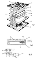
- Fig. 1 eine perspektivische Explosionsansicht einer verwendbaren Folientastatur;
- Fig. 2 einen schematischen Schnitt durch diese Tastatur mit der Schlageinrichtung; und
- Fig. 3 ein Blockschaltbild der entsprechenden Schaltung.
- Figure 1 is an exploded perspective view of a usable membrane keyboard.
- 2 shows a schematic section through this keyboard with the striking device; and
- Fig. 3 is a block diagram of the corresponding circuit.
Die in Fig. 1 beispielsweise dargestellte Folientastatur besitzt eine steife Frontplatte 1, z.B. aus Metall, auf welcher Tastenfelder 2 angeordnet sind. Auf diese Tastenfelder ausgerichtet sind Kontaktfolien 3, 4, zwischen welchen pro Tastenfeld je ein Piezoelement 5 angeordnet und von einer Halteplatte 6 zentriert sind. Die Folientastatur ist von einem Gehäuse 7 eingeschlossen, an welches sich ein Aufnahmeteil 8 für die Interfaceschaltung 9 anschliesst. Frontplatte 1, Gehäuse 7 und Aufnahmeteil 8 sind mechanisch zu einer Einheit verbunden. Die Tastenbetätigung erfolgt wegfrei, indem die Kraft, welche auf ein Tastenfeld ausgeübt wird, ohne merkliche Verformung der Frontplatte 1 auf das jeweilige Piezoelement übertragen wird. Die dadurch zwischen den Oberflächen des Piezoelementes erzeugte Piezospannung wird über die Kontaktfolien abgegriffen und von der Interface-Schaltung 9 in bekannter Weise zu Signalen verarbeitet.The membrane keyboard shown in FIG. 1, for example, has a
In Fig. 2, worin Teile der Folientastatur weggelassen sind, ist eine Schlagvorrichtung 10, 11, 12 ersichtlich, welche am Gehäuse 7 angeordnet und damit mechanisch mit der Frontplatte 1 verbunden ist.FIG. 2, in which parts of the membrane keyboard are omitted, shows a
Die Schlagvorrichtung besteht im vorliegenden Ausführungsbeispiel aus einer kleinen Spule 11, innerhalb welcher ein Kern 10 beweglich gelagert und z.B. mittels einer Feder (nicht dargestellten) gehalten ist. Der bewegliche Kern 10 wirkt als Schlagbolzen gegen einen Vorsprung 12, der am Gehäuse befestigt ist. Er kann selbstverständlich auch direkt auf das Gehäuse wirken. Wesentlich ist dabei die mechanische Verbindung zur Frontplatte 1 zur Uebertragung des mechanischen Impulses in den Tastenbereich.In the present exemplary embodiment, the striking device consists of a
Bei jeder ausreichenden Tastenbetätigung wird die Schlagvorrichtung mit vernachlässigbarer Zeitverzögerung ausgelöst, so dass der mechanische Impuls auf den noch auf der Taste liegenden Finger übertragen und taktil wahrgenommen wird. Gleichzeitig wird ein Anschlaggeräusch erzeugt.Each time the button is pressed sufficiently, the impact device is triggered with a negligible time delay, so that the mechanical impulse is transmitted to the finger still on the button and is felt tactilely. At the same time, an impact sound is generated.
Im beschriebenen Ausführungsbeispiel wirkt die einzige Schlagvorrichtung für alle Tastenfelder gemeinsam. Dies ist nicht störend, da in der Regel nur jeweils der betätigende Finger das Tastenfeld berührt und die Quittierung an der Berührungsstelle wahrnimmt. Es sind aber auch Ausführungen denkbar, bei welchen einzelnen Tastengruppen eigene Schlagvorrichtungen der genannten Art zugeordnet sind.In the exemplary embodiment described, the single striking device acts jointly for all keypads. This is not annoying, since usually only the actuating finger touches the keypad and perceives the acknowledgment at the point of contact. However, versions are also conceivable in which individual key groups are assigned their own striking devices of the type mentioned.
Die Spule 11 der Schlagvorrichtung ist an eine Treiberschaltung 13 angeschlossen, welche einen kurzen Stromimpuls durch die Spule 11 erzeugt. Der bewegliche Kern 10 wird dadurch in Richtung des Vorsprungs 12 angetrieben und schlägt dort auf, wodurch der mechanische Impuls erzeugt wird. Mittels der Haltefeder (nicht dargestellt) wird der Kern dann wieder in seine Ausgangslage zurückgeführt. Die Treiberschaltung 13 stellt sicher, dass die Schlagvorrichtung nur dann einen Impuls erzeugt, wenn auch ein verwertbares elektrisches Tastensignal auftritt. Zu diesem Zweck ist sie an die Interface-Schaltungen 9 für die Tasten angeschlossen. Erst wenn die Interface-Schaltung 9 ein verwertbares Signal feststellt, das einen eingestellten Spannungsschwellwert übersteigt, wird die Schlagvorrichtung 10, 11, 12 ausgelöst.The
Die anhand einer speziellen Folientastatur beschriebene Vorrichtung eignet sich generell für elektronische Tastaturen ohne mechanischen Anschlag, indem sie diesen simuliert und dem Benutzer damit eine klare Quittung für einen für eine wirksame Tastenbetätigung taktil vermittelt. Insbesondere bei wegfreien Tastaturen kann damit die Eingabesicherheit wesentlich verbessert werden.The device described on the basis of a special membrane keyboard is generally suitable for electronic keyboards without a mechanical stop, in that it simulates this and thus provides the user with a clear receipt for a tactile actuation for an effective key actuation. The input security can thus be significantly improved, in particular in the case of pathless keyboards.
Der Schlagbolzen 10 könnte in Abänderung des beschriebenen Ausführungsbeispieles auch pneumatisch oder hydraulisch betätigt werden.The firing pin 10 could also be actuated pneumatically or hydraulically in a modification of the exemplary embodiment described.
Claims (7)
- Acknowledging device in an electronic keyboard for acknowledging the operation of keys, characterized by at least one electrically triggerable stroking device (10, 11, 12) being triggerable at the occurrence of a key signal and being mechanically connected to the key zone (1), such that the generated mechanical momentum is transmitted to said keys (2).
- Acknowledging device according to claim 1, characterized in that the stroking device comprises of a coil (11) with a movable core (10) arranged therein, said core acting on a member (12) mechanically connected to said keyboard, when the coil is energized.
- Acknowledging device according to one of the preceding claims, characterized in that the stroking device (10, 11, 12) is electrically connected to a driving circuit, which is connected to a keyboard interface circuit (13).
- Acknowledging device according to one of the preceding claims, characterized in that the keyboard comprises travelless keys (2).
- Acknowledging device according to one of the preceding claims, characterized in that the keyboard is a membrane keyboard.
- Acknowledging device according to one of the preceding claims, characterized in that the keyboard comprises a mechanically rigid front plate (1) having key areas (2) defined thereon, wherein said stroking device (10, 11, 12) is mechanically coupled to the front plate (1).
- Acknowledging device according to one of the preceding claims, characterized in that only one stroking device (10, 11, 12) is provided for each keyboard, wherein the stroking device (10, 11, 12) is triggerable by every key signal.
Priority Applications (1)
| Application Number | Priority Date | Filing Date | Title |
|---|---|---|---|
| AT88810085T ATE80495T1 (en) | 1987-02-11 | 1988-02-11 | DEVICE ON ELECTRONIC KEYBOARDS FOR ACKNOWLEDGING KEYPRESS. |
Applications Claiming Priority (2)
| Application Number | Priority Date | Filing Date | Title |
|---|---|---|---|
| CH520/87A CH672560A5 (en) | 1987-02-11 | 1987-02-11 | |
| CH520/87 | 1987-02-11 |
Publications (3)
| Publication Number | Publication Date |
|---|---|
| EP0278916A2 EP0278916A2 (en) | 1988-08-17 |
| EP0278916A3 EP0278916A3 (en) | 1989-03-22 |
| EP0278916B1 true EP0278916B1 (en) | 1992-09-09 |
Family
ID=4188883
Family Applications (1)
| Application Number | Title | Priority Date | Filing Date |
|---|---|---|---|
| EP88810085A Expired - Lifetime EP0278916B1 (en) | 1987-02-11 | 1988-02-11 | Device for indicating the actuation of a key in electronic keyboards |
Country Status (4)
| Country | Link |
|---|---|
| EP (1) | EP0278916B1 (en) |
| AT (1) | ATE80495T1 (en) |
| CH (1) | CH672560A5 (en) |
| DE (1) | DE3804308A1 (en) |
Cited By (13)
| Publication number | Priority date | Publication date | Assignee | Title |
|---|---|---|---|---|
| US8309870B2 (en) | 2011-01-04 | 2012-11-13 | Cody George Peterson | Leveled touchsurface with planar translational responsiveness to vertical travel |
| US8624839B2 (en) | 2009-10-15 | 2014-01-07 | Synaptics Incorporated | Support-surface apparatus to impart tactile feedback |
| US8760413B2 (en) | 2009-01-08 | 2014-06-24 | Synaptics Incorporated | Tactile surface |
| US8847890B2 (en) | 2011-01-04 | 2014-09-30 | Synaptics Incorporated | Leveled touchsurface with planar translational responsiveness to vertical travel |
| US8912458B2 (en) | 2011-01-04 | 2014-12-16 | Synaptics Incorporated | Touchsurface with level and planar translational travel responsiveness |
| US8927890B2 (en) | 2011-03-07 | 2015-01-06 | Synaptics Incorporated | Capacitive keyswitch technologies |
| US9040851B2 (en) | 2012-08-06 | 2015-05-26 | Synaptics Incorporated | Keycap assembly with an interactive spring mechanism |
| US9177733B2 (en) | 2012-08-06 | 2015-11-03 | Synaptics Incorporated | Touchsurface assemblies with linkages |
| US9213372B2 (en) | 2013-04-19 | 2015-12-15 | Synaptics Incorporated | Retractable keyboard keys |
| US9218927B2 (en) | 2012-08-06 | 2015-12-22 | Synaptics Incorporated | Touchsurface assembly with level and planar translational responsiveness via a buckling elastic component |
| US9224554B2 (en) | 2013-03-14 | 2015-12-29 | Synaptics Incorporated | Anti-tilt and rotation techniques for a touchsurface assembly having translating keys |
| US9324515B2 (en) | 2012-08-06 | 2016-04-26 | Synaptics Incorporated | Touchsurface assembly utilizing magnetically enabled hinge |
| US9349552B2 (en) | 2010-05-24 | 2016-05-24 | Synaptics Incorporated | Touchpad with capacitive force sensing |
Families Citing this family (7)
| Publication number | Priority date | Publication date | Assignee | Title |
|---|---|---|---|---|
| FR2629227B1 (en) * | 1988-03-25 | 1992-12-24 | Sfena | TOUCH EFFECT COMMUNICATION TERMINAL |
| FR2652445B1 (en) * | 1989-09-22 | 1993-05-28 | Sextant Avionique | METHOD FOR STIMULATING THE FINGER OF AN OPERATOR ACTING ON A STATIC KEYBOARD AND DEVICE FOR CARRYING OUT SAID METHOD. |
| JP2527854B2 (en) * | 1991-06-10 | 1996-08-28 | 富士通株式会社 | Variable drag device and key switch device |
| US5982304A (en) * | 1997-03-24 | 1999-11-09 | International Business Machines Corporation | Piezoelectric switch with tactile response |
| FI112415B (en) | 2001-11-28 | 2003-11-28 | Nokia Oyj | Piezoelectric user interface |
| US8310349B2 (en) * | 2009-09-29 | 2012-11-13 | Visteon Global Technologies, Inc. | Haptic surface with mechanical buttons |
| DE102011110471A1 (en) * | 2011-08-17 | 2013-02-21 | Continental Automotive Gmbh | operating device |
Family Cites Families (3)
| Publication number | Priority date | Publication date | Assignee | Title |
|---|---|---|---|---|
| EP0020118A1 (en) * | 1979-05-24 | 1980-12-10 | Arthur G. Crimmins | Finger control system |
| US4467321A (en) * | 1982-04-30 | 1984-08-21 | Volnak William M | Chording keyboard for generating binary data |
| MX160213A (en) * | 1984-12-18 | 1990-01-04 | Henry C Penner | IMPROVEMENTS IN TWO-WAY COMMUNICATION KEYBOARD |
-
1987
- 1987-02-11 CH CH520/87A patent/CH672560A5/de unknown
-
1988
- 1988-02-09 DE DE3804308A patent/DE3804308A1/en not_active Withdrawn
- 1988-02-11 EP EP88810085A patent/EP0278916B1/en not_active Expired - Lifetime
- 1988-02-11 AT AT88810085T patent/ATE80495T1/en active
Cited By (15)
| Publication number | Priority date | Publication date | Assignee | Title |
|---|---|---|---|---|
| US8760413B2 (en) | 2009-01-08 | 2014-06-24 | Synaptics Incorporated | Tactile surface |
| US8624839B2 (en) | 2009-10-15 | 2014-01-07 | Synaptics Incorporated | Support-surface apparatus to impart tactile feedback |
| US9349552B2 (en) | 2010-05-24 | 2016-05-24 | Synaptics Incorporated | Touchpad with capacitive force sensing |
| US8847890B2 (en) | 2011-01-04 | 2014-09-30 | Synaptics Incorporated | Leveled touchsurface with planar translational responsiveness to vertical travel |
| US8912458B2 (en) | 2011-01-04 | 2014-12-16 | Synaptics Incorporated | Touchsurface with level and planar translational travel responsiveness |
| US8309870B2 (en) | 2011-01-04 | 2012-11-13 | Cody George Peterson | Leveled touchsurface with planar translational responsiveness to vertical travel |
| US9430050B2 (en) | 2011-01-04 | 2016-08-30 | Synaptics Incorporated | Touchsurface with level and planar translational travel responsiveness |
| US8927890B2 (en) | 2011-03-07 | 2015-01-06 | Synaptics Incorporated | Capacitive keyswitch technologies |
| US9040851B2 (en) | 2012-08-06 | 2015-05-26 | Synaptics Incorporated | Keycap assembly with an interactive spring mechanism |
| US9218927B2 (en) | 2012-08-06 | 2015-12-22 | Synaptics Incorporated | Touchsurface assembly with level and planar translational responsiveness via a buckling elastic component |
| US9324515B2 (en) | 2012-08-06 | 2016-04-26 | Synaptics Incorporated | Touchsurface assembly utilizing magnetically enabled hinge |
| US9177733B2 (en) | 2012-08-06 | 2015-11-03 | Synaptics Incorporated | Touchsurface assemblies with linkages |
| US9224554B2 (en) | 2013-03-14 | 2015-12-29 | Synaptics Incorporated | Anti-tilt and rotation techniques for a touchsurface assembly having translating keys |
| US9384919B2 (en) | 2013-03-14 | 2016-07-05 | Synaptics Incorporated | Touchsurface assembly having key guides formed in a sheet metal component |
| US9213372B2 (en) | 2013-04-19 | 2015-12-15 | Synaptics Incorporated | Retractable keyboard keys |
Also Published As
| Publication number | Publication date |
|---|---|
| EP0278916A2 (en) | 1988-08-17 |
| CH672560A5 (en) | 1989-11-30 |
| DE3804308A1 (en) | 1988-09-08 |
| ATE80495T1 (en) | 1992-09-15 |
| EP0278916A3 (en) | 1989-03-22 |
Similar Documents
| Publication | Publication Date | Title |
|---|---|---|
| EP0278916B1 (en) | Device for indicating the actuation of a key in electronic keyboards | |
| EP3417356B1 (en) | Motor-vehicle operating device having a resiliently mounted actuating element and operating haptics | |
| EP1550202B1 (en) | Energy-autarchic electromechanical radio switch | |
| EP1913612B1 (en) | Control element for a motor vehicle | |
| DE102017119757A1 (en) | Haptic actuator, electronic device and method for generating haptic feedback | |
| WO2017001033A1 (en) | Automotive operating device with haptic feedback | |
| DE1290569C2 (en) | MECHANICALLY OPERATED BUTTON FOR A KEYPAD TRANSMITTER WITH A MAGNETICALLY RESPONDING CONTACT SET, IN PARTICULAR FOR TELEPHONE DEVICES | |
| WO2017001032A1 (en) | Motor vehicle operating device having a centred actuating element | |
| WO2007057266A1 (en) | Touch-sensitive control unit with tactile feedback | |
| WO2017020975A1 (en) | Motor-vehicle operating device having decoupling for a force sensor and a haptic actuator, and motor vehicle | |
| DE4111756C2 (en) | Keyboard for an electronic musical instrument | |
| DE1286087B (en) | Mechano-electric converter with a manually operated key element that can be inserted into a keyboard | |
| DE4312771C2 (en) | Two-stage button | |
| EP3355474B1 (en) | Switching device for converting a manual and/or mechanical motion into a switching signal | |
| DE2214105A1 (en) | Button operating mechanism | |
| EP1545177B1 (en) | Centering frame and module comprising it | |
| EP1715497B1 (en) | Operating device with switching mat | |
| EP3767437B1 (en) | User interface and method for providing feedback in a user interface | |
| DE202013101126U1 (en) | Arrangement for generating commands in flat keyboards | |
| DE102015008538B4 (en) | Motor vehicle operating device with rotatably mounted control panel | |
| EP4017751A1 (en) | Operator control unit for a vehicle, and vehicle | |
| DE2124046B2 (en) | Electric on and off switch | |
| JPH07326253A (en) | Switch operating mechanism | |
| WO1993005527A1 (en) | Electric switch, in particular push-button switch | |
| DE3017010C2 (en) | Keypad, in particular for telephone technology |
Legal Events
| Date | Code | Title | Description |
|---|---|---|---|
| PUAI | Public reference made under article 153(3) epc to a published international application that has entered the european phase |
Free format text: ORIGINAL CODE: 0009012 |
|
| AK | Designated contracting states |
Kind code of ref document: A2 Designated state(s): AT BE FR GB IT LU NL SE |
|
| PUAL | Search report despatched |
Free format text: ORIGINAL CODE: 0009013 |
|
| AK | Designated contracting states |
Kind code of ref document: A3 Designated state(s): AT BE FR GB IT LU NL SE |
|
| 17P | Request for examination filed |
Effective date: 19890508 |
|
| RAP1 | Party data changed (applicant data changed or rights of an application transferred) |
Owner name: DYNALAB AG |
|
| 17Q | First examination report despatched |
Effective date: 19910925 |
|
| ITF | It: translation for a ep patent filed |
Owner name: STUDIO INGG. FISCHETTI & WEBER |
|
| GRAA | (expected) grant |
Free format text: ORIGINAL CODE: 0009210 |
|
| AK | Designated contracting states |
Kind code of ref document: B1 Designated state(s): AT BE FR GB IT LU NL SE |
|
| REF | Corresponds to: |
Ref document number: 80495 Country of ref document: AT Date of ref document: 19920915 Kind code of ref document: T |
|
| GBT | Gb: translation of ep patent filed (gb section 77(6)(a)/1977) | ||
| ET | Fr: translation filed | ||
| PLBE | No opposition filed within time limit |
Free format text: ORIGINAL CODE: 0009261 |
|
| STAA | Information on the status of an ep patent application or granted ep patent |
Free format text: STATUS: NO OPPOSITION FILED WITHIN TIME LIMIT |
|
| 26N | No opposition filed | ||
| PGFP | Annual fee paid to national office [announced via postgrant information from national office to epo] |
Ref country code: FR Payment date: 19940119 Year of fee payment: 7 |
|
| PGFP | Annual fee paid to national office [announced via postgrant information from national office to epo] |
Ref country code: SE Payment date: 19940124 Year of fee payment: 7 Ref country code: BE Payment date: 19940124 Year of fee payment: 7 |
|
| PGFP | Annual fee paid to national office [announced via postgrant information from national office to epo] |
Ref country code: GB Payment date: 19940201 Year of fee payment: 7 |
|
| PGFP | Annual fee paid to national office [announced via postgrant information from national office to epo] |
Ref country code: NL Payment date: 19940228 Year of fee payment: 7 Ref country code: LU Payment date: 19940228 Year of fee payment: 7 Ref country code: AT Payment date: 19940228 Year of fee payment: 7 |
|
| EPTA | Lu: last paid annual fee | ||
| EAL | Se: european patent in force in sweden |
Ref document number: 88810085.6 |
|
| PG25 | Lapsed in a contracting state [announced via postgrant information from national office to epo] |
Ref country code: LU Free format text: LAPSE BECAUSE OF NON-PAYMENT OF DUE FEES Effective date: 19950211 Ref country code: GB Effective date: 19950211 Ref country code: AT Effective date: 19950211 |
|
| PG25 | Lapsed in a contracting state [announced via postgrant information from national office to epo] |
Ref country code: SE Effective date: 19950212 |
|
| PG25 | Lapsed in a contracting state [announced via postgrant information from national office to epo] |
Ref country code: BE Effective date: 19950228 |
|
| BERE | Be: lapsed |
Owner name: DYNALAB A.G. Effective date: 19950228 |
|
| PG25 | Lapsed in a contracting state [announced via postgrant information from national office to epo] |
Ref country code: NL Effective date: 19950901 |
|
| GBPC | Gb: european patent ceased through non-payment of renewal fee |
Effective date: 19950211 |
|
| PG25 | Lapsed in a contracting state [announced via postgrant information from national office to epo] |
Ref country code: FR Effective date: 19951031 |
|
| NLV4 | Nl: lapsed or anulled due to non-payment of the annual fee |
Effective date: 19950901 |
|
| EUG | Se: european patent has lapsed |
Ref document number: 88810085.6 |
|
| REG | Reference to a national code |
Ref country code: FR Ref legal event code: ST |
|
| PG25 | Lapsed in a contracting state [announced via postgrant information from national office to epo] |
Ref country code: IT Free format text: LAPSE BECAUSE OF NON-PAYMENT OF DUE FEES;WARNING: LAPSES OF ITALIAN PATENTS WITH EFFECTIVE DATE BEFORE 2007 MAY HAVE OCCURRED AT ANY TIME BEFORE 2007. THE CORRECT EFFECTIVE DATE MAY BE DIFFERENT FROM THE ONE RECORDED. Effective date: 20050211 |