EP0285997A1 - Electronic postage meter with a large number of auxiliary counters - Google Patents
Electronic postage meter with a large number of auxiliary counters Download PDFInfo
- Publication number
- EP0285997A1 EP0285997A1 EP88105168A EP88105168A EP0285997A1 EP 0285997 A1 EP0285997 A1 EP 0285997A1 EP 88105168 A EP88105168 A EP 88105168A EP 88105168 A EP88105168 A EP 88105168A EP 0285997 A1 EP0285997 A1 EP 0285997A1
- Authority
- EP
- European Patent Office
- Prior art keywords
- counter
- counters
- message
- key
- action
- Prior art date
- Legal status (The legal status is an assumption and is not a legal conclusion. Google has not performed a legal analysis and makes no representation as to the accuracy of the status listed.)
- Ceased
Links
Images


Classifications
-
- G—PHYSICS
- G07—CHECKING-DEVICES
- G07B—TICKET-ISSUING APPARATUS; FARE-REGISTERING APPARATUS; FRANKING APPARATUS
- G07B17/00—Franking apparatus
- G07B17/00185—Details internally of apparatus in a franking system, e.g. franking machine at customer or apparatus at post office
- G07B17/00193—Constructional details of apparatus in a franking system
-
- G—PHYSICS
- G07—CHECKING-DEVICES
- G07B—TICKET-ISSUING APPARATUS; FARE-REGISTERING APPARATUS; FRANKING APPARATUS
- G07B17/00—Franking apparatus
- G07B17/00185—Details internally of apparatus in a franking system, e.g. franking machine at customer or apparatus at post office
- G07B17/00362—Calculation or computing within apparatus, e.g. calculation of postage value
-
- G—PHYSICS
- G07—CHECKING-DEVICES
- G07B—TICKET-ISSUING APPARATUS; FARE-REGISTERING APPARATUS; FRANKING APPARATUS
- G07B17/00—Franking apparatus
- G07B17/00185—Details internally of apparatus in a franking system, e.g. franking machine at customer or apparatus at post office
- G07B17/00193—Constructional details of apparatus in a franking system
- G07B2017/00266—Man-machine interface on the apparatus
- G07B2017/00274—Mechanical, e.g. keyboard
-
- G—PHYSICS
- G07—CHECKING-DEVICES
- G07B—TICKET-ISSUING APPARATUS; FARE-REGISTERING APPARATUS; FRANKING APPARATUS
- G07B17/00—Franking apparatus
- G07B17/00185—Details internally of apparatus in a franking system, e.g. franking machine at customer or apparatus at post office
- G07B17/00362—Calculation or computing within apparatus, e.g. calculation of postage value
- G07B2017/00395—Memory organization
Definitions
- the invention relates to the operation of an electronic franking machine comprising auxiliary counters and in particular a large number of auxiliary counters.
- a franking machine is equipped with a counter which accumulates the total value of the frankings carried out since the putting into service of the machine, and of some additional counters to help the user to better manage his expenses of franking, for example for distribute the said postage expenses among several budget items.
- additional meters made available to the user, make it possible to accumulate, within a given period of time, the number and / or the total value of postage made.
- the user To manage these additional counters, the user must be able to name it for each counter taken individually, turn it on, off, zero, and view it.
- French patent application 87 02 667 Operating system of an electronic franking machine describes a franking machine equipped with several auxiliary counters, for example about twenty, and a keyboard comprising a key menu, in addition to the numeric keys.
- a franking machine allows on the one hand carrying out normal franking operations and on the other hand carrying out specific operations using the menu key, in particular selecting an auxiliary counter and switching it on and off, or resetting it.
- Each auxiliary counter is a double counter, that is to say it comprises a cash counter which totals the values of the postage made during a given period of time, and a fold counter totaling the number of envelopes or of stamped labels during said period of time.
- Each auxiliary counter is designated by a number which corresponds to the space occupied by this counter in a reserved memory space, in a memory, for example a working memory, for all of the auxiliary counters, said memory being backed up by a battery.
- the user must therefore either memorize the meaning of each counter or maintain an identification list in order to identify each counter number.
- the user can memorize the signaling of each counter, but even for about twenty counters he will most often have recourse to an identification list, and such a list becomes practically necessary when the number of counters exceeds twenty and reached a few tens.
- the object of the invention is to remedy these drawbacks and to allow the selection of a counter without having to use an identification list.
- the subject of the invention is a franking machine, comprising a keyboard equipped with ten numeric keys, a validation key, a cancellation key, a star key, a menu key and two scroll keys, one arrow up, the other arrow down, an alphanumeric type display, a clock / calendar, a microprocessor, a program memory, a text memory, a working memory backed up by a battery, and an audible alarm linked by a bus, the working memory containing, in a Counter space, auxiliary counters each consisting of bytes of working memory and having a cash counter and a mail counter themselves constituted by bytes, a first set of messages for normal franking operations and a second set of messages for particular operations being stored in the text memory, the program memory containing programs relating to each message of the first and second set of messages, the second set of messages being accessible by the menu key, pressing on said menu key causes a first message.
- auxiliary counters are identified by a name and that they are stored in alphabetical order, one after the other, in the counter space of the working memory.
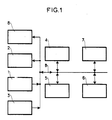
- FIG. 1 is a block diagram of part of an electronic circuit of an electronic machine to which the invention applies.
- the franking machine is of the type described in French patent application 87 02667, already cited; it includes a keyboard 1, a display 2, a calendar clock 3, a microprocessor 4, a program memory 5, a text memory 6, which is a ROM type ROM, a working memory 7 of RAM type, an alarm sound 8, connected by a bus B.
- the display is for example an alphanumeric display having a display capacity of L lines of N characters each, for example 2 lines of 16 characters.
- the text memory 6 contains a first set of messages for normal franking operators and a second set of messages for particular operations accessible by a menu key M on the keyboard.
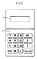
- FIG. 2 represents a keyboard display assembly equipping the machine; keyboard 1 has 10 numeric keys, a menu key M, a CANCEL cancellation key, a star key *, a VALID validation key and two scroll keys, one arrow up, the other arrow down, i.e. 16 keys total.
- the messages are displayed on display 2; for this the program memory 5 contains as many programs as there are messages, each program being relative to a message.
- the messages are divided into screens each having a number L of lines of N characters equal to the number L of lines of N characters that the display can visualize.
- An alphanumeric display allows you to view all the characters appearing in the ASCII code, also known as CCITT code No. 5.
- Each screen of a message is transferred, by the program relating to said message, from the text memory 6 to a memory space of the working memory 7, this space being called display image IA and having NL bytes, each byte being assigned to a character of a line.
- the display is carried out using a display program which is a specific program, contained in the program memory 5, which runs automatically every 100 milliseconds.
- This specific program is used to take the information from the bytes of the display image IA and transfer them to display 2 for viewing.
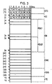
- FIG. 3 represents a part of the content of the working memory 7, this part comprising: - two bytes ITC0 and ITC1 for a temporary ITC keyboard image, - two bytes IC0 and IC1 for a keyboard image IC.
- the numbers, letters and signs are those of the 16 keys on the keyboard, M denoting the menu, V confirming and Canceling, each key corresponding to 1 bit of the bytes.
- thirty-two bytes IA0 to IA31 for the display image IA the bytes IA0 to IA15 being reserved for the first line EiL1 of a screen Ei, the bytes IA16 to IA31 being reserved for the second line EiL2 of the screen Ei, this of course in the case of a display of two lines of sixteen characters, - six bytes IHC0 to ICH5 for a clock, calendar image;
- the IHC0 byte is reserved for the year from 0 to 99;
- the IHC1 byte is reserved for the months 1 to 12;
- the IHC2 byte is reserved for the day from 1 to 31;
- the IHC3 byte is reserved for the hour, from 0 to 23;
- the IHC4 byte is reserved per minute, from 0 to 59;
- the IHC5 byte is reserved for
- a specific keyboard acquisition program which runs automatically every 20 milliseconds, is used to take the state of the keys on the keyboard and store them in the temporary ITC keyboard image; if this state does not change for at least 50 milliseconds, the image temporary keyboard is transferred to the keyboard image IC.
- a specific date and time acquisition program which runs automatically every 100 milliseconds, is used to take the content of six counters constituting the calendar clock (year, month, day, hour, minute and second) and transfer it to the IHC clock / calendar image.
- a specific audible alarm control program which runs automatically every 20 millseconds, is used to take the information contained in the three bytes of the CAS audible alarm control image and to transfer it to the audible alarm. 8 of the machine. These bytes are loaded by each program relating to a message, the audible alarm consisting of audible beeps. After each beep emitted, the first byte CAS0 is decremented by one.
- a specific timer program which runs automatically every 20 milliseconds, is used for the timers. It consists of doing -1 in the timer byte TE0 if the content of this byte is not zero, then starting again on the timer byte TE1.
- the second and third bytes of the audible alarm control CAS and the delay bytes TE0 and TE1 are loaded by a number; this number multiplied by the cycle time of the specific program gives the desired time; for example for a screen delay of 1 second, the number 50 is loaded into the TE0 delay byte.
- the working memory backed up by a battery, also contains the auxiliary counters in a reserved memory space, hereinafter referred to as the Counter space.
- the Counter space a reserved memory space
- the invention relates in particular to a large number of auxiliary counters, several tens for example, each counter being designated no longer by its number, but by its name, the counters being arranged, in the Counters area, in alphabetical order of their title ( name) which consists of alphanumeric characters.
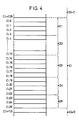
- FIG. 4 represents the occupation, in the Counter space, of a auxiliary counter Ci of the invention.
- a service area, Z1 of 4 bytes, the use of which will be specified below
- - a zone entitled, Z2 10 bytes reserved for storing the name, each byte containing a character part of the columns 3, 4 and 5 of the ASCII code (CCITT No. 5); the characters in these columns have a code between the hexadecimal values 30 and 5A which include: the 10 digits, 0 to 9, the signs; greater than, equal, less than, question mark, a round, and the 26 letters of the alphabet, - a 5 byte date and time zone for resetting the auxiliary counter, Z3.
- the information in this area is binary coded, and the 5 bytes contain, in order year, 0 to 99 (AA) the month, from 1 to 12 (MM) during the day, from 1 to 31 (DD) the hour, from 0 to 23 (HH) per minute, from 0 to 59 (mm) - an area for accumulating postage values, Z4, of 4 bytes.
- This area is a cash counter with a maximum capacity of 42,949,672.96 francs; it corresponds to a 32-bit binary counter, - an area for accumulating the number of frankings, Z5, of 3 bytes.
- This zone is a fold counter with a maximum capacity of 16,777,215 folds; it corresponds to a 24-bit counter.
- each auxiliary counter which and a double counter, occupies a memory space of 26 bytes, in the example described above; one could obviously have a zone of title Z2 of less than 10 bytes, or even of 16 bytes to use the display capacity of a line of the display in the case of a line with 16 characters.
- the number of bytes in area Z2 is defined by the manufacturer of the franking machine; the number of 10 bytes is therefore a value taken by way of example, this value appearing sufficient to allow a counter to be identified by its title.
- the bytes of an auxiliary counter Ci are identified by Cio, Ci1, ... Ci 25.
- the bytes Ci0 to Ci 3 are those of the service area Z1
- the bytes Ci4 to Ci13 are those of the title area Z2
- the bytes Ci14 to Ci18 are those of the date and time zone of reset Z3
- the bytes Ci 19 to Ci 22 are those of the cash counter zone Z4
- the bytes Ci 23 to Ci 25 are those of the Z5 fold counter area.
- the reset of an auxiliary counter Ci is carried out by loading 0 in the 7 bytes Ci 19 to Ci 25.
- the date and time of this reset are recorded in the 5 bytes Ci 14 to Ci 18; this is obtained by transferring the first five bytes of the clock / calendar image into bytes Ci 14 to Ci 18 of the auxiliary counter Ci.
- the date and time recorded make it possible to specify the duration of operation of the auxiliary counter; the time separating two resets defines the periodicity of the counter, this periodicity being determined by the user according to his needs.
- the auxiliary counters are arranged in alphabetical order by their titles.
- auxiliary counters being, according to the invention, designated by their title and no longer by their number, pressing the key 2 when viewing the message MP0 brings up the message MP 20.
- This message consists of the following four screens:
- Screens 1 to 4 are displayed for 3, 1, 1, 1 seconds respectively.
- the number of the counter appearing on screen 1 corresponds to the rank occupied by counter in the Counter space; three characters are assigned to the number of a counter. This number, for the same counter title, may vary depending on the creations and deletions. Thus, if the DURAND counter bears the number 22 at a given instant, it will have the number 23 following the creation of the DUPONT counter which precedes, in alphabetical order, the DURAND counter, the DUPONT counter then having number 22.
- a short press on the 1 key increments the counter number in screen 1 by 1 and brings up the name of the next counter. Following this action, the message MP 21 is reset and the screen 1 appears for 3 seconds.
- the operator keeps the key 1 pressed for more than a second, he triggers the accelerated advance, obtained by the program relating to the message MP 21 which then simulates short, increasingly rapid presses of the key 1.
- the program relating to the message MP 21 which then simulates short, increasingly rapid presses of the key 1.
- the title of the next counter appears one second, then the next one appears after 0.9 seconds, then the next one appears after 0.8 seconds, and so on, up to 0.3 seconds.
- Key 2 has the same function as key 1, but exploration of the Counter space is done in reverse.
- the text of the message MP 21, like all the messages, is stored in the text memory 6 of the franking machine.
- the programs relating to the messages MP 21 to MP 23 use a memory space "Search" of seven bytes, from the working memory 7, these successive bytes being arranged starting from the symbolic address Search 0 which is that of the first byte.
- an initialization program determines the number n of counters present in the counter space, n being less than or equal to Q which is the maximum number of counters that the space can contain Counters.
- the first 32 bytes of the message MP 21 (screen 1) from the text memory into the display image IA of the working memory, from the address IA0, which is that of the first byte of this display image.
- the first 32 bytes of the MP 21 message correspond to a 2-line display of 16 characters, taken as an example. Take m, number of the counter, in R1 and put it away, after processing (change to decimal then to ASCII code), in the display image IA at addresses IA12, I13 and IA14 (three digits maximum).
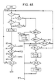
- the SPMP 21 subroutine shown in FIGS. 6A and 6B carries out the following actions, designated by SP1, SP2, ... etc.
- This action is the initialization phase for pressing keys 1 or 2 (see SP1).
- Load 1 second (50) into R4 which is the memory byte of the acceleration delay (MT).
- This action is the phase of decrease of the display time of the names of the counters (see SP1).
- Action SP 13 selection of the next or previous counter.
- n the number of existing counters
- This message appears following an action on the key 3 when viewing the message MP21.
- the message MP22 includes the following eight screens:
- Screens 1 to 8 are displayed for 2, 1, 3, 2, 2, 2, 2 seconds, respectively.
- the counter number, line 1, and its title (name), line 2 are those that were displayed in screen 1 of the message MP21 when the operator chose option "3 - The to consult".
- the counter number is contained in byte R1
- its title is contained in the 10 bytes Ci4 to Ci13 of the zone Z2 of the counter, the starting address AC + 4 of Ci4 in the Counter space being given by the content, AC, of R2 and R3, to which we add 4. This is identical to what is indicated in action 1 of the message MP21.
- the date and time, line 2 of screen 2 are those of the last reset, and are contained in the 5 bytes of zone Z3 of the counter, from address AC + 14, AC being given by the content of R2 and R3 to which 14 is added.
- the two pieces of information on screen 4 are extracted from the zone Z4 of the counter on line 1, and from the zone Z5 of the counter for line 2.
- zone Z4 of the counter If the cumulative cash, zone Z4 of the counter, and the cumulative number of folds, zone Z5 of the counter, are at zero, the proposition "3 - Reset, from screen 6 does not appear; it is replaced, in bytes IA16 to IA31 of the display image, with space symbols.
- Propositions 4 and 5 of screen 7 are mutually exclusive; only the inverse proposition of the state of the counter displayed appears.
- the first service byte, zone Z1 of the meter contains the letter M, the proposition "4 - Stop it” appears, but not the proposition "5 - Start it”;
- the first service byte contains the letter A, the proposition "4 - Stop it” does not appear, but the proposition "5 - The Start” appears.
- This message consists of the following 3 screens:
- the text of the second line of screen 1 is: a reset (key 3) a stop (key 4) starting (key 5) deletion (key 6)
- the text of the second line of screen 2 consists of the title of the counter, which is the same as that which appeared on the second line of screen 1 of the message MP22 when the operator pressed one of the keys 3, 4, 5 or 6.
- Pressing the cancel key also returns to the message MP22, but without executing the order.
- the letter A (code 41 in hexadecimal) is loaded in the first service byte of the counter, with address AC. From this moment the counter no longer accumulates cash or folds.
- the letter M (code 4D in hexadecimal) is loaded in place of the letter A in the first service byte of the counter which then accumulates cash and folds.
- the following program runs: Read the otect of address AC + 26 and write it to the address AC; the byte of address AC + 26 is the first service byte of the following counter, Read the byte of address AC + 27 and write it to the address AC + 1, and so on by increasing each time the read address and the write address, until the transfer of the last byte of the last counter, that is to say when the read address has become equal to C10 + 26n-1, the address C10 being that of the first byte of the Counter space in the working memory, the write address then being equal to C10 + 26 (n-1) -1.
- the creation of a counter consists of composing its title, then the name being validated, to find the place it must occupy in the Counter space.
- the Counter space contains the DUPONT and DURAND counters, and a DUPUIS counter is created, this must be stored between the DUPONT and DURAND counters, to observe the alphabetical order. This is obtained by shifting all the counters located after the DUPONT counter by one position (this operation is identical to deleting, but performed in reverse) and inserting the DUPUIS counter. Of course, you can only create a new counter if n is less than Q.
- the search for the place of the new counter whose name has just been composed, the shifting of the counters and the loading of the bytes of the new counter are carried out using a storage program which takes place when the name has been composed .
- the first counter to be shifted must be searched for; for this the storage program uses the well-known method of dichotomous research.
- the last byte of the last counter n used with address C10 + 26n-1 in the Counter space, is read and written at the address C10 + 26 (n + 1) -1 which is that of the last byte of counter n + 1 , and so on by doing -1 in the read and write addresses until the read address is equal to the AC address of the first byte of the first counter to be shifted, which ends the shift of counters.
- the display times of screens 1 to 5 are 3, 1, 1, 1, 1 seconds respectively.
- the name of a counter can have a maximum of 10 characters, since it has been assumed that the counter title area Z2 has 10 bytes (one per character).
- the frame rate is 1 character every 0.8 seconds. when the letter Z appears, the next character is the number 0, so the sequence of admissible characters is completed, and the appearance of the number 0 causes the emission of a beep to signal to the operator the start of a character scrolling cycle.
- a fleeting action on key 1 immediately brings up the next character; following this action the message MP25 is reset, the scrolling of characters is suspended, and screen 1 is displayed for 3 seconds.
- Key 2 has the same function as key 1, but causes the characters to scroll in reverse order.
- Pressing key 3 validates the displayed character and initiates the scrolling of characters to the position immediately to the right of the validated character. If the validated character is the tenth of the name, the scrolling does not appear on the next position, this one being off screen.
- the key 4 allows to return to the previous position with erasure of the position which has just been left.
- Key 5 is used by the operator to indicate to the franking machine the end of the composition of the name.
- the procedure for storing the new meter among the meters existing ones is then engaged, this procedure starting, as indicated above, by the search for the first counter to shift.
- the implementation of the program relating to the message MP25 uses a "Title" zone of 15 bytes of the working memory whose symbolic addresses are INT0 to INT14. We find in order, at the different addresses: INT0 to INT9: Ten bytes assigned to the name of the counter being created, INT 10: reserve byte, INT 11: position in the name of the character being created, INT 12: memory of the scroll delay, INT 13: key phase INT 14: automatic scrolling authorized or not.
- the MP25 message program performs actions, some of which use a SPMP25 subroutine from the MP25 message program.
- FIG. 7 The flowchart of the program relating to the message MP25 is shown in FIG. 7, and the flowchart of the sub-program SPMP25 is shown in FIGS. 8A and 8B.
- the program relating to the MP25 message includes the following actions:
- Action 1 Initialization of the composition of the name.
- Action 5 Display of the screen 3.
- Action 7 Display of the screen 5.
- the SPMP25 subroutine is used to check the flow of the screen delay, TE0 byte, and to manage the actions on keys 1, 2, 3, 4, 5 and cancellation; it follows the following actions, designated by SP1, SP2, ...:
- the corresponding bit in the IC keyboard image has the value o, wait for the operator to release it, i.e. the value of the corresponding bit in the IC keyboard image changes to 1, then: if the content of the address byte INT11 is less than 10, add 1 to this content and return to action 2 of the program, otherwise, return to action 2, without modifying the content of the byte of INT11 address. If key 3 is not pressed go to action SP3.
- Cancel key is pressed, return to the message MP20, it is the abandonment of the creation of a counter; end of program for message MP25. If the cancel key is not pressed and if the menu key is pressed return to the message MP0. If the menu key is not pressed go to action SP6.
- Action SP10 Initialization of pressing keys 1 and 2.
- Action SP12 Waiting for the scrolling time to elapse.
- auxiliary counters can be running simultaneously; at the limit, all the counters in the Counters area can be running.
- the value of the stamp which has just been issued must be added to each of the cash counters (zone Z4 of each auxiliary counter) and the number of folds of each fold counter (zone Z5 of each auxiliary counter), must be increased by one unit. This operation can be relatively long, and while it is being carried out, it is necessary to prohibit the production of the next franking, which reduces the performance of the franking machine.
- the procedure chosen consists in realigning the auxiliary meters in operation, no longer after each franking, but at privileged times.
- the time separating two privileged moments constitutes the realignment period.
- the method consists in accumulating the total of postage in a counter "Consumption period" of 4 bytes in the working memory, and to add 1, after each postage, in a counter of "Period folds" and 3 bytes in the working memory .
- a realignment program examines the first byte Cio of each auxiliary counter. If the content of this byte is the letter A (stop) the program goes to the next auxiliary counter.
- the program adds the content of the counter "Period consumption” to the content of the cash counter of the auxiliary counter, and it adds the content of the counter "Period folds” to the fold counter of this same auxiliary counter, then the realignment program examines the next auxiliary counter. When the last auxiliary counter in operation is realigned, the program resets the "Period consumption” and "Period folds" counters. The realignments are carried out: When switching on the franking machine; these are the accumulations of postage which took place before the power cut, When the message MP20 "Search or create a counter" appears. At the appearance of the message MP22 consultation of a counter, following a confirmation of a request to shutdown (message MP23).
- An auxiliary counter can have one or more sub-counters (notion of total and subtotal).
- a counter becomes under counter if its title is that of an auxiliary counter to which we add the @ sign (a circle) followed, possibly, by a text, numbers or letters.
- the operator creates a first "Store” counter, then a second "Store @ 1" counter; this second counter is a sub-counter of the first.
- the second service byte, Ci1 of each counter is used, this byte contains the letter C for a counter (absence of @ in its title) and the letter S for a sub-counter (presence of the @ sign in its title).
- a sub-counter can be deleted independently of the other sub-counters of the same counter, but the deletion of a counter automatically deletes all the sub-counters which are attached to it.
- each sub-counter of a counter can be zeroed independently of the others, but resetting a counter automatically causes all of its sub-counters to be reset to zero.
- Switching on or off a counter automatically switches on or off the sub-meters attached to it.
- a sub-counter cannot be switched on or off independently of the counter to which it is attached.
- FIGS 5, 6A, 6B, 7, 8A and 8B are flow charts, as indicated above.
- FIGS. 6A, 6B, 8A, 8B the numbers 1, 2, ..., the letters, A, M, V which appear in the diamonds designate the numeric keys, cancel (A), menu (M), validation (V).
- the number 1 means yes, and the number 0 means no.
- the reference DEB means start of the program, or of the sub-program.
- references AI, AII, etc. denote the actions of the corresponding program.
- the reference PR means program for storing the counter in the Counter space.
Abstract
Description
L'invention est relative à l'exploitation d'une machine à affranchir électronique comportant des compteurs auxiliaires et notamment un grand nombre de compteurs auxiliaires.The invention relates to the operation of an electronic franking machine comprising auxiliary counters and in particular a large number of auxiliary counters.
Généralement une machine à affranchir est équipée d'un compteur qui cumule la valeur totale des affranchissements réalisés depuis la mise en service de la machine, et de quelques compteurs supplémentaires pour aider l'usager à mieux gérer ses dépenses d'affranchissements, par exemple pour répartir les dites dépenses d'affranchissements entre plusieurs postes budgétaires. Ces compteurs supplémentaires, mis à la disposition de l'usager, permettent de cumuler, dans une période de temps donnée, le nombre et/ou la valeur totale des affranchissements réalisés. Pour gérer ces compteurs supplémentaires il faut que l'usager puisse, pour chaque compteur pris individuellement, le nommer, le mettre en marche, à l'arrêt, à zéro, et le visualiser.Generally a franking machine is equipped with a counter which accumulates the total value of the frankings carried out since the putting into service of the machine, and of some additional counters to help the user to better manage his expenses of franking, for example for distribute the said postage expenses among several budget items. These additional meters, made available to the user, make it possible to accumulate, within a given period of time, the number and / or the total value of postage made. To manage these additional counters, the user must be able to name it for each counter taken individually, turn it on, off, zero, and view it.
Ceci est effectué par le clavier de la machine à affranchir, en équipant celui-ci de touches supplémentaires ou en autorisant l'action simultanée sur deux ou trois touches du clavier ; cette manière d'opérer n'est envisageable que pour un très petit nombre de compteurs supplémentaires deux ou trois par exemple. Pour un plus grand nombre de compteurs supplémentaires il faut soit multiplier le nombre de touches supplémentaires, soit généraliser la technique des doubles ou triples appuis, mais dans ce cas un lexique accompagnant la machine devient nécessaire et l'usager doit s'y reporter chaque fois qu'il désire sélectionner l'un des compteurs supplémentaires.This is done by the keyboard of the franking machine, by equipping it with additional keys or by authorizing simultaneous action on two or three keys on the keyboard; this way of operating is only possible for a very small number of additional meters two or three for example. For a larger number of additional counters it is necessary either to multiply the number of additional keys, or to generalize the technique of double or triple presses, but in this case a lexicon accompanying the machine becomes necessary and the user must refer to it each time that he wishes to select one of the additional counters.
Si l'on désire pouvoir arrêter, mettre à zéro, ou demander individuellement chaque compteur supplémentaire, il faut prévoir des touches supplémentaires, de sorte que le clavier devient d'un usage lourd, mal commode, déroutant pour l'usager, et nécessitant pour celui-ci un certain temps de formation.If you want to be able to stop, zero, or request each additional counter individually, you must provide additional keys, so that the keyboard becomes heavy, inconvenient, confusing for the user, and requiring to this one some training time.
La demande de brevet français 87 02 667 Système d'exploitation d'une machine à affranchir électronique, déposée le 28 février 1987, décrit une machine à affranchir équipée de plusieur compteurs auxiliaires, par exemple une vingtaine, et d'un clavier comportant une touche menu, en plus des touches numériques. Une telle machine permet d'une part la réalisation des opérations normales d'affranchissement et d'autre part la réalisation d'opérations particulières à partir de la touche menu, en particulier la sélection d'un compteur auxiliaire et sa mise en marche, à l'arrêt, ou sa remise à zéro. Chaque compteur auxiliaire est un compteur double, c'est-à-dire qu'il comporte un compteur d'espèces qui totalise les valeurs des affranchissements réalisés pendant une période de temps donné, et un compteur de plis totalisant le nombre d'enveloppes ou d'étiquettes affranchies pendant ladite période de temps. Chaque compteur auxiliaire est désigné par un numéro qui correspond à la place occupée par ce compteur dans un espace mémoire réservé, dans une mémoire, par exemple une mémoire de travail, à l'ensemble des compteurs auxiliaires, ladite mémoire étant secourue par une pile.French patent application 87 02 667 Operating system of an electronic franking machine, filed on February 28, 1987, describes a franking machine equipped with several auxiliary counters, for example about twenty, and a keyboard comprising a key menu, in addition to the numeric keys. Such a machine allows on the one hand carrying out normal franking operations and on the other hand carrying out specific operations using the menu key, in particular selecting an auxiliary counter and switching it on and off, or resetting it. Each auxiliary counter is a double counter, that is to say it comprises a cash counter which totals the values of the postage made during a given period of time, and a fold counter totaling the number of envelopes or of stamped labels during said period of time. Each auxiliary counter is designated by a number which corresponds to the space occupied by this counter in a reserved memory space, in a memory, for example a working memory, for all of the auxiliary counters, said memory being backed up by a battery.
L'usager doit donc soit mémoriser la signification de chaque compteur, soit tenir à jour une liste d'identification afin d'identifier chaque numéro de compteur.The user must therefore either memorize the meaning of each counter or maintain an identification list in order to identify each counter number.
Pour quelques compteurs l'usager peut mémoriser la signalisation de chaque compteur, mais même pour une vingtaine de compteurs il aura le plus souvant recours à une liste d'identification, et une telle liste devient pratiquement nécessaire lorsque le nombre de compteurs dépasse une vingtaine et atteint quelques dizaines.For some counters the user can memorize the signaling of each counter, but even for about twenty counters he will most often have recourse to an identification list, and such a list becomes practically necessary when the number of counters exceeds twenty and reached a few tens.
La consultation d'une telle liste d'identification et sa mise à jour en fonction des créations et des suppressions des compteurs entraînent des pertes de temps et sont causes de risques d'erreurs.The consultation of such an identification list and its updating according to the creations and deletions of the counters lead to loss of time and are causes of risks of errors.
Le but de l'invention est de remédier à ces inconvénients et de permettre la sélection d'un compteur sans avoir recours à une liste d'identification.The object of the invention is to remedy these drawbacks and to allow the selection of a counter without having to use an identification list.
L'invention a pour objet une machine à affranchir, comportant un clavier équipé de dix touches numériques, d'une touche validation, d'une touche annulation, d'une touche étoile, d'une touche menu et de deux touches de défilement, l'une flèche en haut, l'autre flèche en bas, un afficheur du type alphanumérique, une horloge/calendrier, un microprocesseur, une mémoire programme, une mémoire de texte, une mémoire de travail secourue par une pile, et une alarme sonore reliés par un bus, la mémoire de travail contenant, dans un espace Compteurs, des compteurs auxiliaires constitués chacun par des octets de la mémoire de travail et ayant un compteur d'espèces et un compteur de plis eux mêmes constitués par des octets, un premier ensemble de messages pour des opérations normales d'affranchissement et un second ensemble de messages pour des opérations particulières étant mémorisés dans la mémoire de texte, la mémoire programme contenant des programmes relatifs à chaque message des premier et deuxième ensembles de messages, le deuxième ensemble de messages étant accessible par la touche menu, un appui sur ladite touche menu faisant apparaître un premier message. Début du menu comportant des options numérotées, chaque numéro correspondant à une touche numérique du clavier, l'une des options permettant d'accéder aux compteurs auxiliaires, caractérisée par le fait que les compteurs auxiliaires sont repérés par un nom et qu'ils sont rangés par ordre alphabétique, à la suite les uns des autres, dans l'espace compteurs de la mémoire de travail.The subject of the invention is a franking machine, comprising a keyboard equipped with ten numeric keys, a validation key, a cancellation key, a star key, a menu key and two scroll keys, one arrow up, the other arrow down, an alphanumeric type display, a clock / calendar, a microprocessor, a program memory, a text memory, a working memory backed up by a battery, and an audible alarm linked by a bus, the working memory containing, in a Counter space, auxiliary counters each consisting of bytes of working memory and having a cash counter and a mail counter themselves constituted by bytes, a first set of messages for normal franking operations and a second set of messages for particular operations being stored in the text memory, the program memory containing programs relating to each message of the first and second set of messages, the second set of messages being accessible by the menu key, pressing on said menu key causes a first message. Beginning of the menu with numbered options, each number corresponding to a numeric key on the keyboard, one of the options allowing access to the auxiliary counters, characterized in that the auxiliary counters are identified by a name and that they are stored in alphabetical order, one after the other, in the counter space of the working memory.
L'invention sera bien comprise par la description qui va suivre d'un exemple de réalisation illustré par les figures annexées dans lesquelles :
- - la figure 1 est un schéma synoptique d'une partie d'un circuit électronique d'une machine à affranchir électronique à laquelle s'applique l'invention,
- - la figure 2 représente un clavier et un afficheur d'une machine à affranchir électronique,
- - La figure 3 représente une partie du contenu d'une mémoire de travail de la machine à affranchir de la figure 1,
- - La figure 4 représente un espace compteur auxiliaire d'un espace Compteurs réservé dans une mémoire aux compteurs auxiliaires de l'invention,
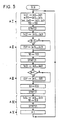
- - La figure 5 est un organigramme d'un programme d'un message MP21 "Recherche d'un compteur",
- - Les figures 6A et 6B représentent un organigramme d'un sous-programme SPMP21 du programme du message MP21,
- - La figure 7 est un organigramme d'un programme d'un message MP25 création d'un compteur,
- - Les figures 8A et 8B représentent un organigramme d'un sous- programme SPMP25 du programme du message MP25.
- FIG. 1 is a block diagram of part of an electronic circuit of an electronic franking machine to which the invention applies,
- FIG. 2 represents a keyboard and a display of an electronic franking machine,
- FIG. 3 represents part of the content of a working memory of the franking machine of FIG. 1,
- FIG. 4 represents an auxiliary counter space of a Counter space reserved in a memory for the auxiliary counters of the invention,
- FIG. 5 is a flow diagram of a program of a message MP21 "Search for a counter",
- FIGS. 6A and 6B represent a flow diagram of a subroutine SPMP21 of the program of the message MP21,
- FIG. 7 is a flow diagram of a program of an MP25 message creating a counter,
- - Figures 8A and 8B show a flow diagram of a sub- SPMP25 program of the MP25 message program.
- La figure 1 est le schéma synoptique d'une partie d'un circuit électronique d'une machine électronique à laquelle s'applique l'invention. La machine à affranchir est du type décrit dans la demande de brevet français 87 02667, déjà cité ; elle comporte un clavier 1, un afficheur 2, une horloge calendrier 3, un microprocesseur 4, une mémoire programme 5, une mémoire de texte 6, qui est une mémoire morte du type ROM, une mémoire de travail 7 du type RAM, une alarme sonore 8, reliés par un bus B. L'afficheur est par exemple un afficheur alphanumérique ayant une capacité d'affichage de L lignes de N caractères chacune, par exemple 2 lignes de 16 caractères. La mémoire de texte 6 contient un premier ensemble de messages pour des opérateurs normales d'affranchissement et un second ensemble de messages pour des opérations particulières accessibles par une touche menu M du clavier.- Figure 1 is a block diagram of part of an electronic circuit of an electronic machine to which the invention applies. The franking machine is of the type described in French patent application 87 02667, already cited; it includes a
La figure 2 représente un ensemble afficheur clavier équipant la machine ; le clavier 1 comporte 10 touches numériques, une touche menu M, une touche annulation ANNUL, une touche étoile *, une touche validation VALID et deux touches défilement, l'une flèche en haut, l'autre flèche en bas, soit 16 touches au total.FIG. 2 represents a keyboard display assembly equipping the machine;
Dans cette machine, les messages sont visualisés sur l'afficheur 2 ; pour cela la mémoire programme 5 contient autant de programmes qu'il y a de messages, chaque programme étant relatif à un message. Les messages sont découpés en écrans ayant chacun un nombre L de lignes de N caractères égal au nombre L de lignes de N caractères que peut visualiser l'afficheur. Un afficheur alphanumérique permet de visualiser tous les caractères figurant dans le code ASCII, également connu sous l'appellation code no 5 du CCITT. Chaque écran d'un message est transféré, par le programme relatif audit message, de la mémoire de texte 6 dans un espace mémoire de la mémoire de travail 7, cet espace étant appelé image afficheur IA et ayant N.L octets, chaque octet étant affecté à un caractère d'une ligne. L'affichage est effectuée à l'aide d'un programme afficheur qui est un programme spécifique, contenu dans la mémoire programme 5, qui se déroule automatiquement toutes les 100 millisecondes.In this machine, the messages are displayed on
Ce programme spécifique est utilisé pour prélever les informations des octets de l'image afficheur IA et les transférer sur l'afficheur 2 pour visualisation.This specific program is used to take the information from the bytes of the display image IA and transfer them to display 2 for viewing.
La figure 3 représente une partie du contenu de la mémoire de travail 7, cette partie comprenant :
- deux octets ITC0 et ITC1 pour une image temporaire clavier ITC,
- deux octets IC0 et IC1 pour une image clavier IC.FIG. 3 represents a part of the content of the
- two bytes ITC0 and ITC1 for a temporary ITC keyboard image,
- two bytes IC0 and IC1 for a keyboard image IC.
Dans ces quatre octets les chiffres, lettres et signes sont ceux des 16 touches du clavier, M désignant le menu, V la validation et A l'annulation, chaque touche correspondant à 1 bit des octets.
- trente deux octets IA0 à IA31 pour l'image afficheur IA, les octets IA0 à IA15 étant réservés à la première ligne EiL1 d'un écran Ei, les octets IA16 à IA31 étant réservés à la deuxième ligne EiL2 de l'écran Ei, ceci bien entendu dans le cas d'un afficheur de deux lignes de seize caractères,
- six octets IHC0 à ICH5 pour une image horloge, calendrier ; l'octet IHC0 est réservé à l'année de 0 à 99 ; l'octet IHC1 est réservé au mois de 1 à 12 ; l'octet IHC2 est réservé au jour de 1 à 31 ; l'octet IHC3 est réservé à l'heure, de 0 à 23 ; l'octet IHC4 est réservé à la minute, de 0 à 59 ; l'octet IHC5 est réservé à la seconde de 0 à 59,
- trois octets CAS0 à à CAS2 pour une commande d'alarme sonore CAS, l'octet CAS0 étant réservé au nombre de bips à émettre, l'octet CAS1 étant réservé au temps d'émission d'un bip, et l'octet CAS2 étant réservé au temps d'un silence (entre deux bip),
- deux octets de temporisation TE0 et TE1, l'octet TE0 étant réservé à la temporisation d'écran, c'est-à-dire au temps d'affichage d'un écran, chaque écran étant affiché pendant un temps qui dépend de son importance ; l'octet TE1 est un nouvel octet de temporisation utilisé lors de l'exécution des messages relatifs aux compteurs auxiliaires de l'invention, et son rôle sera précisé lors de la présentation des messages.In these four bytes, the numbers, letters and signs are those of the 16 keys on the keyboard, M denoting the menu, V confirming and Canceling, each key corresponding to 1 bit of the bytes.
thirty-two bytes IA0 to IA31 for the display image IA, the bytes IA0 to IA15 being reserved for the first line EiL1 of a screen Ei, the bytes IA16 to IA31 being reserved for the second line EiL2 of the screen Ei, this of course in the case of a display of two lines of sixteen characters,
- six bytes IHC0 to ICH5 for a clock, calendar image; the IHC0 byte is reserved for the year from 0 to 99; the IHC1 byte is reserved for the
- three bytes CAS0 to through CAS2 for a CAS audible alarm command, the byte CAS0 being reserved for the number of beeps to be emitted, the byte CAS1 being reserved for the time of emission of a beep, and the byte CAS2 being reserved for the time of silence (between two beeps),
- two timer bytes TE0 and TE1, the TE0 byte being reserved for the screen timer, that is to say the display time of a screen, each screen being displayed for a time which depends on its importance; the TE1 byte is a new time delay byte used during the execution of the messages relating to the auxiliary counters of the invention, and its role will be specified during the presentation of the messages.
Un programme spécifique d'acquisition clavier, qui se déroule automatiquement toutes les 20 millisecondes, sert à prélever l'état des touches du clavier et à le ranger dans l'image temporaire clavier ITC ; si cet état ne change pas pendant au moins 50 millisecondes, l'image temporaire clavier est transférée dans l'image clavier IC.A specific keyboard acquisition program, which runs automatically every 20 milliseconds, is used to take the state of the keys on the keyboard and store them in the temporary ITC keyboard image; if this state does not change for at least 50 milliseconds, the image temporary keyboard is transferred to the keyboard image IC.
Un Programme spécifique d'acquisition de la date et de l'heure, qui se déroule automatiquement toutes les 100 millisecondes, sert à prelever le contenu de six compteurs constituant l'horloge calendrier (année, mois, jour, heure, minute et seconde) et à le transférer dans l'image horloge/calendrier IHC.A specific date and time acquisition program, which runs automatically every 100 milliseconds, is used to take the content of six counters constituting the calendar clock (year, month, day, hour, minute and second) and transfer it to the IHC clock / calendar image.
Un programme spécifique de commande de l'alarme sonore, qui se déroule automatiquement toutes les 20 millsecondes, sert à prélever les informations contenues dans les trois octets de l'image commande de l'alarme sonore CAS et à les transférer à l'alarme sonore 8 de la machine. Ces octets sont chargés par chaque programme relatif à un message, l'alarme sonore étant constituée par des bips sonores.Après chaque bip émis le premier octet CAS0 est décrémenté d'une unité.A specific audible alarm control program, which runs automatically every 20 millseconds, is used to take the information contained in the three bytes of the CAS audible alarm control image and to transfer it to the audible alarm. 8 of the machine. These bytes are loaded by each program relating to a message, the audible alarm consisting of audible beeps. After each beep emitted, the first byte CAS0 is decremented by one.
Un programme spécifique de temporisation, qui se déroule automatiquement toutes les 20 millisecondes, est utilisé pour les temporisations. Il consiste à faire -1 dans l'octet de temporisation TE0 si le contenu de cet octet n'est pas nul, puis à recommencer sur l'octet de temporisation TE1.A specific timer program, which runs automatically every 20 milliseconds, is used for the timers. It consists of doing -1 in the timer byte TE0 if the content of this byte is not zero, then starting again on the timer byte TE1.
Les deuxième et troisième octets de la commande d'alarme sonore CAS et les octets de temporisation TE0 et TE1 sont chargés par un nombre ; ce nombre multiplié par le temps de cycle du programme spécifique donne le temps désiré ; par exemple pour une temporisation d'écran de 1 seconde, le nombre 50 est chargé dans l'octet de temporisation TE0.The second and third bytes of the audible alarm control CAS and the delay bytes TE0 and TE1 are loaded by a number; this number multiplied by the cycle time of the specific program gives the desired time; for example for a screen delay of 1 second, the
La mémoire de travail, secourue par une pile, contient également les compteurs auxiliaires dans un espace mémore réservé, désigné ci-après par espace Compteurs. Dans la demande de brevet français 87 02667, déjà citée, ces compteurs sont au nombre d'une vingtaine, chaque compteur étant désigné par son numéro.The working memory, backed up by a battery, also contains the auxiliary counters in a reserved memory space, hereinafter referred to as the Counter space. In French patent application 87 02667, already cited, there are about twenty of these counters, each counter being designated by its number.
L'invention concerne notamment un grand nombre de compteurs auxiliaires, plusieurs dizaines par exemple, chaque compteur étant désigné non plus par son numéro, mais par son nom, les compteurs étant rangés, dans l'espace Compteurs, par ordre alphabétique de leur intitulé (nom) qui est constitué de caractères alphanumériques.The invention relates in particular to a large number of auxiliary counters, several tens for example, each counter being designated no longer by its number, but by its name, the counters being arranged, in the Counters area, in alphabetical order of their title ( name) which consists of alphanumeric characters.
La figure 4 représente l'occupation, dans l'espace Compteurs, d'un compteur auxilaires Ci de l'invention. Dans la figure 4 on constate la présence de cinq zones d'informations :
- une zone de service, Z1, de 4 octets, dont l'utilisation sera précisée plus loin,
- une zone d'intitulé, Z2, de 10 octets, réservée au stockage du nom, chaque octet contenant un caractère faisant partie des colonnes 3, 4 et 5 du code ASCII (code no 5 du CCITT) ; les caractères qui font partie de ces colonnes ont un code compris entre les valeurs hexadécimales 30 et 5A qui comprennent : les 10 chiffres, 0 à 9, les signes ; supérieur à, égal, inférieur à, point d'interrogation, a rond, et les 26 lettres de l'alphabet,
- une zone date et heure de la remise à zéro du compteur auxiliaire, Z3, de 5 octets. Les informations de cette zone sont codées en binaire, et les 5 octets contiennent, dans l'ordre
l'année, de 0 à 99 (AA)
le mois, de 1 à 12 (MM)
le jour, de 1 à 31 (JJ)
l'heure, de 0 à 23 (HH)
la minute, de 0 à 59 (Mm)
- une zone de cumul des valeurs d'affranchissement, Z4, de 4 octets. Cette zone est un compteur d'espèces dont la capacité maximum est de 42 949 672, 96 francs ; elle correspond à un compteur binaire de 32 bits,
- une zone de cumul du nombre d'affranchissements, Z5, de 3 octets. Cette zone est un compteur de plis dont la capacité maximum est de 16 777 215 plis ; elle correspond à un compteur de 24 bits.FIG. 4 represents the occupation, in the Counter space, of a auxiliary counter Ci of the invention. In Figure 4 we see the presence of five information zones:
- a service area, Z1, of 4 bytes, the use of which will be specified below,
- a zone entitled, Z2, 10 bytes reserved for storing the name, each byte containing a character part of the
- a 5 byte date and time zone for resetting the auxiliary counter, Z3. The information in this area is binary coded, and the 5 bytes contain, in order
year, 0 to 99 (AA)
the month, from 1 to 12 (MM)
during the day, from 1 to 31 (DD)
the hour, from 0 to 23 (HH)
per minute, from 0 to 59 (mm)
- an area for accumulating postage values, Z4, of 4 bytes. This area is a cash counter with a maximum capacity of 42,949,672.96 francs; it corresponds to a 32-bit binary counter,
- an area for accumulating the number of frankings, Z5, of 3 bytes. This zone is a fold counter with a maximum capacity of 16,777,215 folds; it corresponds to a 24-bit counter.
Au total, chaque compteur auxiliaire, qui et un double compteur, occupe un espace mémoire de 26 octets, dans l'exemple décrit dessus ; on pourrait bien évidemment avoir une zone d'intitulé Z2 de moins de 10 octets, ou encore de 16 octets pour utiliser la capacité de visualisation d'une ligne de l'afficheur dans le cas d'une ligne à 16 caractères. Le nombre d'octets de la zone Z2 est défini par le constructeur de la machine à affranchir ; le nombre de 10 octets est donc une valeur prise à titre d'exemple, cette valeur paraissant suffisante pour permettre d'identifier un compteur par son intitulé.In total, each auxiliary counter, which and a double counter, occupies a memory space of 26 bytes, in the example described above; one could obviously have a zone of title Z2 of less than 10 bytes, or even of 16 bytes to use the display capacity of a line of the display in the case of a line with 16 characters. The number of bytes in area Z2 is defined by the manufacturer of the franking machine; the number of 10 bytes is therefore a value taken by way of example, this value appearing sufficient to allow a counter to be identified by its title.
L'espace Compteurs, en mémoire de travail, nécessaire pour 200 compteurs auxiliaires est de 26 x 200 = 5200 octets. Si la mémoire de travail utilisée a une capacité de 8 192 octets, il reste dans ce cas 2 992 octets pour les autres informations nécessiares au fonctionnement de la machine : image temporaire clavier, image clavier, image afficheur, image horloge/calendrier, commande d'alarme sonore, temporisations, etc.The Counter space, in working memory, necessary for 200 auxiliary counters is 26 x 200 = 5200 bytes. If the working memory used has a capacity of 8,192 bytes, in this case 2,992 bytes remain for the other information necessary for the operation of the machine: temporary keyboard image, keyboard image, display image, clock / calendar image, control of alarm, timers, etc.
Les octets d'un compteur auxiliaire Ci sont repérés par Cio, Ci1,... Ci 25. Les octets Ci0 à Ci 3, sont ceux de la zone de service Z1, les octets Ci4 à Ci13 sont ceux de la zone d'intitulé Z2, les octets Ci14 à Ci18 sont ceux de la zone date et heure de la remise à zéro Z3, les octets Ci 19 à Ci 22 sont ceux de la zone compteur d'espèces Z4, et les octets Ci 23 à Ci 25 sont ceux de la zone compteur de plis Z5.The bytes of an auxiliary counter Ci are identified by Cio, Ci1, ...
La remise à zéro d'un compteur auxiliaire Ci s'effectue en chargeant 0 dans les 7 octets Ci 19 à Ci 25.The reset of an auxiliary counter Ci is carried out by loading 0 in the 7
A chaque remise à zéro la date et l'heure de cette remise à zéro sont enregistrées dans les 5 octets Ci 14 à Ci 18 ; ceci est obtenu en transférant les cinq premiers octets de l'image horloge/calendrier dans les octets Ci 14 à Ci 18 du compteur auxiliaire Ci. La date et l'heure enregistrées permettent de préciser la durée de fonctionnement du compteur auxiliaire ; le temps séparant deux remises à zéro définit la périodicité du compteur, cette périodicité étant déterminée par l'utilisateur en fonction de ses besoins.At each reset the date and time of this reset are recorded in the 5
Dans l'espace compteurs, les compteurs auxiliaires sont rangés par ordre alphabétique de leur intitulés.In the counter area, the auxiliary counters are arranged in alphabetical order by their titles.
Cet espace Compteurs est prévu pour contenir, par exemple, Q = 200 compteurs auxiliaires repérés C1, C2,...CQ ; si seulement n compteurs ont été affectés (n inférieur à Q) alors le premier octet de service de la zone Z1 du compteur suivant, C(n + 1), contient le caractère ETX (03 en hexadécimal) ; la présence de ce caractère (fin de texte du tableau ASCII) traduit la fin de l'ensemble des n compteurs.This Counter space is designed to contain, for example, Q = 200 auxiliary counters marked C1, C2, ... CQ; if only n counters have been assigned (n less than Q) then the first service byte of zone Z1 of the following counter, C (n + 1), contains the character ETX (03 in hexadecimal); the presence of this character (end of text in the ASCII table) translates the end of all n counters.
On va décrire à présent la manière, pour l'usager, d'accéder aux compteurs auxilaires.We will now describe the way for the user to access the auxiliary meters.
L'exécution de programmes relatifs aux différents messages concernant les compteurs auxiliaires qui seront mentionnés plus loin, nécessite, comme déjà mentionné, la présence, dans la mémoire de travail, d'un autre octet de temporisation TE1 dont le rôle sera précisé lors de la présentation des messages.The execution of programs relating to the various messages concerning the auxiliary counters which will be mentioned later, requires, as already mentioned, the presence, in the working memory, of another time delay byte TE1 whose role will be specified during the presentation of messages.
Comme dans la demande de brevet français 8 702 667 déjà citée, l'accès aux compteurs auxilaires se fait par la touche menu M du clavier ; un appui sur cette touche fait apparaître un message MP0, Début du Menu. Ce message est le premier du deuxième ensemble de messages, et comporte des options numérotées accessibles par le clavier, et en particulier une optionAs in the French patent application 8 702 667 already cited, access to the auxiliary counters is done by the menu key M on the keyboard; pressing this key brings up a message MP0, Start of the Menu. This message is the first of the second set of messages, and includes numbered options accessible via the keyboard, and in particular an option
L'opérateur sélectionne cette option en appuyant sur la touche numérique 2 indiquée dans cet écran, ce qui va lui permettre d'accéder aux messages suivants, spécifiques à l'invention puisque les compteurs sont désignés par leur intitulé :
MP 20 Recherche ou Création d'un compteur
MP 21 Recherche d'un compteur
MP 22 Consultation d'un compteur
MP 23 Confirmation de l'état sélectionné d'un compteur
MP 25 Composition du nom (d'un compteur).The operator selects this option by pressing the
MP 22 Counter consultation
MP 23 Confirmation of the selected state of a counter
Les compteurs auxiliaires étant, selon l'invention, désignés par leur intiulé et non plus par leur nombre, l'appui sur la touche 2 lors de la visualisation du message MP0 fait apparaître le message MP 20.The auxiliary counters being, according to the invention, designated by their title and no longer by their number, pressing the key 2 when viewing the message MP0 brings up the
Message MP 20 Recherche ou création d'un compteur.
Ce message est constitué par les trois écrans suivants :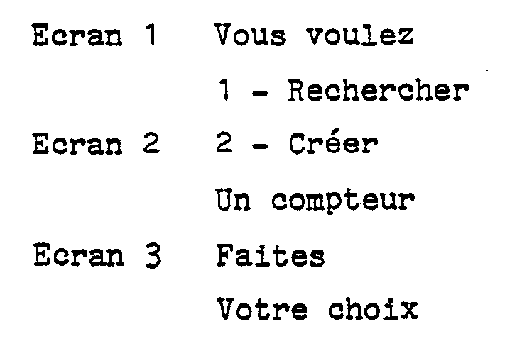
1 - Rechercher, de la deuxième ligne de l'écran 1 n'apparait pas ; la touche 1 du clavier est inactive.
- Si l'espace Compteurs est plein, tous les compteurs ayant été affectés on a n = Q, il est impossible d'affecter un nouveau compteur et la proposition, 2 - Créer, de la première ligne de l'écran 2 n'apparaît pas ; la touche 2 du clavier est inactive.
- Si le nombre n de compteurs affectés est inférieur au nombre Q de compteurs que peut contenir l'espace Compteurs, un appui sur la touche 1 fait apparaître le message MP21 Recherche d'un compteur, et un appui sur la touche 2 fait apparaître le message MP25 Composition du nom (d'un compteur).This message consists of the following three screens:
1 - Search, from the second line of
- If the Counter space is full, all the counters having been assigned on an = Q, it is impossible to assign a new counter and the proposal, 2 - Create, from the first line of
- If the number n of counters assigned is less than the number Q of counters that the Counter space can contain, pressing the key 1 brings up the message MP21 Search for a counter, and pressing the key 2 brings up the message MP25 Composition of the name (of a counter).
Ce message est constitué par les quatre écrans suivant :
Les écrans 1 à 4 sont affichés pendant 3, 1, 1, 1 secondes respectivement.
Le numéro du compteur apparaissant sur l'écran 1 correspond au rang occupé par compteur dans l'espace Compteurs ; trois caractères sont affectés au numéro d'un compteur. Ce numéro, pour un même intitulé de compteur, peut varier en fonction des créations et suppressions. Ainsi, si le compteur DURAND porte le numéro 22 à un instant donné, il aura le numéro 23 à la suite de la création du compteur DUPONT qui précède, dans l'ordre alphabétique, le compteur DURAND, le compteur DUPONT ayant alors le numéro 22.The number of the counter appearing on
A la ligne 2 de l'écran 1, le nom du compteur apparaît ; il est constitué des dix caractères de l'intitulé du compteur qui sont contenus dans la zone Intitulé, Z2, dudit compteur (dans l'hypothèse d'une zone d'intitulé de 10 octets).In
Lorsque le message MP 21 apparaît pour la première fois, à la suite du message MP 20, le compteur proposé dans l'écran 1 est le premier des n compteurs de l'espace Compteurs, le numéro affiché est donc le numéro 1.When the
Une action sur la touche d'annulation du clavier pendant l'affichage des écrans du message MP 21 ramène au message MP 20.
- Lorsque dans l'écran 1 le numéro du compteur est le numéro 1, la proposition "2 - Le Précédent", de la première ligne de l'écran 3 n'apparait pas et la touche 2 est sans action.
- Lorsque le numéro du compteur est le dernier des n compteurs, et que n est inférieur à Q, le premier octet de service du compteur n + 1, non encore affecté, contient l'indication ETX ; alors la proposition "1 - Le suivant", de la deuxième ligne de l'acran 2, n'apparaît pas, et la touche 1 est inactive.Pressing the cancel key on the keyboard while the screens for
- When in
- When the counter number is the last of the n counters, and that n is less than Q, the first service byte of the counter n + 1, not yet assigned, contains the indication ETX; then the proposition "1 - The next one", from the second line of
Une action brève sur la touche 1 incrémente de 1 le numéro du compteur de l'écran 1 et fait apparaître le nom du compteur suivant. A la suite de cette action le message MP 21 est réinitialisé et l'écran 1 apparait pendant 3 secondes. Une suite d'actions brèves sur la touche 1, se succédant à une cadence inférieure à 3 secondes, fait apparaître en permanence l'écran 1 avec défilement successifs des numéros et des noms des compteurs, au rythme des appuis sur la touche 1.A short press on the 1 key increments the counter number in
Si l'opérateur maintient la touche 1 enfoncée plus d'une seconde, il enclenche l'avance accélérée, obtenue par le programme relatif au message MP 21 qui simule alors des appuis brefs, de plus en plus rapides de la touche 1. Au bout d'une seconde l'intitulé du compteur suivant apparait, puis le suivant apparait au bout de 0,9 seconde, puis le suivant apparait au bout de 0,8 seconde, et ainsi de suite, jusqu'à 0,3 seconde. A partir de 0,3 seconde, le programme ne présente qu'un intitulé sur deux pendant 0,3 seconde, puis un intitulé sur trois pendant 0,3 seconde, puis un intitulé sur quatre, et ainsi de suite. De cette façon si les Q compteurs de l'espace Compteur ont été affectés et si Q = 200, l'ensemble des Q compteurs est parcouru en moins de 11 secondes.If the operator keeps the key 1 pressed for more than a second, he triggers the accelerated advance, obtained by the program relating to the
Lorsque le dernier compteur est atteint, ou dépassé, un bip sonore est émis par l'alarme sonore équipant la machine à affranchir.When the last counter is reached, or exceeded, an audible beep is emitted by the audible alarm equipping the franking machine.
La touche 2 a la même fonction que la touche 1, mais l'exploration de l'espace Compteurs se fait en sens inverse.
Une action sur la touche 3 fait apparaître le message MP 22 Consultation d'un compteur.Pressing
Le texte du message MP 21, comme tous les messages, est rangé dans la mémoire de texte 6 de la machine à affranchir. Le texte du message MP 21 occupe 4 x 32 = 128 octets de la mémoire de texte.The text of the
Les programmes relatifs aux messages MP 21 à MP 23 utilisent un espace mémoire " Recherche" de sept octets, de la mémoire de travail 7, ces octets successifs étant rangés à partir de l'adresse symbolique Recherche 0 qui est celle du premier octet.The programs relating to the
Ces octets, désignés ci-après par R0, R1,... R6 contiennent :
R0 = n, nombre de compteurs existants,
R1 = m, numéro du compteur visualisé,
R2, R3 = AC, adresse courante du premier octet du compteur visualisé
R4 = MT, mémoire de la temporisation d'accélération,
R5 = INC, incrément du nombre de compteurs à enjamber dans la fonction accélération,
R6 = PHAT, phase des touches.These bytes, designated below by R0, R1, ... R6 contain:
R0 = n, number of existing counters,
R1 = m, number of the counter displayed,
R2, R3 = AC, current address of the first byte of the counter displayed
R4 = MT, acceleration delay memory,
R5 = INC, increment in the number of meters to step over in the acceleration function,
R6 = PHAT, phase of the keys.
Lors du passage du message MP 20 au message MP 21, un programme d'initialisation détermine le nombre n de compteurs présents dans l'espace Compteurs, n étant inférieur ou égal à Q qui est le nombre maximal de compteurs que peut contenir l'espace Compteurs. Le programme d'initalisation range ce nombre n dans l'octect R0, puis charge le nombre m = 1 dans l'octet R1 et l'adresse AC du premier octet du premier compteur dans les octets R2 et R3.When passing from the
Le bon déroulement du programme relatif au message MP 21 nécessite la présence d'un sous-programme SPMP 21 de ce programme, pour vérifier l'écoulement de la temporisation d'écran et gérer les conditions de sortie (action sur les touches 1, 2, 3 et annulation).The proper running of the program relating to the
Ce sous-programme sera décrit après le programme relatif au message MP 21 qui comprend les cinq actions suivantes, représentées par l'organigramme de la figure 5 :
This subroutine will be described after the program relating to the
Transférer les 32 premiers octets du message MP 21 (écran 1) de la mémoire de texte dans l'image afficheur IA de la mémoire de travail, depuis l'adresse IA0, qui est celle du premier octet de cette image afficheur. Les 32 premiers octets du message MP 21 correspondent à un afficheur de 2 lignes de 16 caractères, pris comme exemple.
Prélever m, numéro du compteur, en R1 et le ranger, après traitement (passage en décimal puis en code ASCII), dans l'image afficheur IA aux adresses IA12, I13 et IA14 (trois chiffres au maximum).
Transférer les 10 octets Cm 4 à Cm 13 de l'intitulé du compteur m dans l'image afficheur depuis l'adresse IA19 ; l'adresse de départ est obtenue en faisant, dans R2 et R3, AC + 4, le transfert portant sur les 10 octets depuis AC + 4 à AC + 13.
Charger la temporisation d'écran à 3 secondes (charger 150 dans l'octet de temporisation d'écran TE0),
Exécuter le sous-programme SPMP 21.
Transfer the first 32 bytes of the message MP 21 (screen 1) from the text memory into the display image IA of the working memory, from the address IA0, which is that of the first byte of this display image. The first 32 bytes of the
Take m, number of the counter, in R1 and put it away, after processing (change to decimal then to ASCII code), in the display image IA at addresses IA12, I13 and IA14 (three digits maximum).
Transfer the 10
Load the screen timeout at 3 seconds (
Run the
Charger dans l'image afficheur IA le texte de l'écran 2, depuis IA0 jusqu'à IA31, Si m = n, le dernier compteur est en cours de visualisation ; alors charger 16 signes d'espace consécutifs dans l'image afficheur depuis IA 16, pour effacer la deuxiéme ligne de l'écran 2 "1 - Le suivant",
Charger l'octet de temposrisation d'écran TE0 à 1 seconde (50 dans cet octet).
Exécuter le sous-programme SPMP 21.
Load the text of
Load the TE0 screen timing byte at 1 second (50 in this byte).
Run the
Tranférer le texte de l'écran 3 de la mémoire de texte dans l'image afficheur IA de la mémoire de travail, de IA0 à IA31, Si m = 1, c'est le premier compteur de l'espace Compteur qui est visualisé ; alors charger 16 signes d'espace (20 en héxadécimal) consécutifs dans l'image afficheur, de IA0 à IA15, pour effacer la proposition "2 - Le Précédent" de la première ligne de l'écran 3.
Charger l'octet de temporisation d'écran TE0 à 1 seconde (50 dans cet octet).
Exécuter le sous-programme SPMP 21.
Transfer the text from
Load the TE0 screen time delay byte to 1 second (50 in this byte).
Run the
Charger le texte de l'écran 4 dans l'image afficheur de IA0 à IA31.
Charger l'octet de temporisation d'écran TE0 à 1 seconde (50 dans cet octet).
Exécuter le sous-programme SPMP 21.
Load the text of
Load the TE0 screen time delay byte to 1 second (50 in this byte).
Run the
Recommencer l'action 1 (rebouclage).Repeat action 1 (loopback).
Le sous-programme SPMP 21 représenté figures 6A et 6B, enchaîne les actions suivantes, désignées par SP1, SP2,...etc.The
Si les touches 1 et 2 ne sont pas enfoncées, les bits correspondants dans l'image clavier IC ont la valeur 1, faire PHAT = 0, c'est-à-dire charger 0 dans R6, puis passer à l'action SP2.If
Si l'une des touches 1 ou 2 est enfoncée, le bit correspondant dans l'image clavier a la valeur 0 ; si m différent de n si la touche 1 est enfoncée ou si m différent de 1 si la touche 2 est enfoncée et si
PHAT = o passer à l'action SP 10
PHAT = 1 passer à l'action SP 11
PHAT = 2 passer à l'action SP 12If one of the
PHAT = o take
PHAT = 1 go to
PHAT = 2 go to
Si la touche 3 est enfoncée, le bit correspondant dans l'image clavier a la valeur 0, passer au message MP 22 ; c'est la fin du programme MP 21.If
Sinon passer à l'action SP3.Otherwise go to action SP3.
Si la touche annulation est enfoncée, le bit correspondant dans l'image clavier a la valeur 0, passer au message MP 20 ; fin du programme MP 21,
Sinon passer à l'action SP4.If the cancel key is pressed, the corresponding bit in the keyboard image has the
Otherwise go to action SP4.
Si la touche menu M est enfoncée passer au message MP0 Début du menu ; sinon passer à l'action SP5.If the menu key M is pressed, go to the message MP0 Start of the menu; otherwise go to action SP5.
Si la temporisation d'écran est écoulée, le contenu de l'octet de temporisation TE0 a la valeur 0, passer à l'action suivante du programme MP 21.If the screen delay has elapsed, the content of the TE0 delay byte has the
Sinon recommencer l'action SP1.Otherwise repeat the action SP1.
Cette action est la phase d'initialisation d'enfoncement des touches 1 ou 2 (voir SP1).
Charger 1 seconde (50) dans R4 qui est l'octet mémoire de la temporisation d'accélération (MT).
Charger 0 dans R5 (INC = 0) qui est l'octet réservé à l'incrément du nombre de compteurs à enjamber dans la fonction d'accélération.
Charger 1 dans l'octet R6 (PHAT = 1).
Passer à l'action SP13 (présenter le nouveau compteur).This action is the initialization phase for pressing
Go to action SP13 (present the new counter).
Cette action est la phase de décroissance du temps d'affichage des noms des compteurs (voir SP1).This action is the phase of decrease of the display time of the names of the counters (see SP1).
Si la temporisation de défilement n'est pas écoulée (contenu de l'octet de temporisation TE1 différent de zéro) retourner à l'action SP1.If the scroll delay has not elapsed (content of the delay byte TE1 other than zero) return to action SP1.
Si la temporisation de défilement est écoulée (contenu de l'octet TE1 = 0), diminuer de 0,1 seconde le temps de défilement dans la mémoire du temps de défilement c'est-à-dire faire -5 au contenu de l'octet R4, puis donner la valeur zéro (INC = 0) à l'incrément du nombre de compteurs à enjamber, c'est-à-dire écrire 0 dans l'octet R5.If the scrolling time has elapsed (content of byte TE1 = 0), decrease the scrolling time in the scrolling time memory by 0.1 seconds, i.e. make -5 the content of the byte R4, then give the value zero (INC = 0) to the increment of the number of counters to step over, that is to say
Si le temps défilement est égal à 0,3 seconde dans la mémoire du temps de défilement (contenu de l'octet R4 = 15) alors passer en phase 2, c'est-à-dire écrire 2 dans l'octet R6 (PHAT = 2).If the scrolling time is equal to 0.3 seconds in the memory of the scrolling time (content of byte R4 = 15) then go to
Passer à l'action SP13 (présenter le nouveau compteur).Go to action SP13 (present the new counter).
Attente de l'écoulement de la temporisation de défilement (voir SP1).Waiting for the scroll time to elapse (see SP1).
Si la temporisation de défilement n'est pas écoulée (contenu de l'octet de temporisation TE1 différent de zéro), retourner à l'action SP1.If the scroll time has not elapsed (content of time delay TE1 non-zero), return to action SP1.
Si la temporisation de défilement est écoulée (contenu de l'octet de temporisation TE1 = 0), passer à l'action SP13.If the scroll delay has elapsed (content of the delay byte TE1 = 0), go to action SP13.
Ajouter + 1 au contenu de l'octet R5 (INC, nombre de compteurs à enjamber).Add +1 to the content of the R5 byte (INC, number of meters to step over).
Si la touche 1 est enfoncée passer à l'action SP14 (compteur suivant), sinon passer à l'action SP15 (compteur précédent).If
Si m +INC est supérieur à n, m étant le numéro du compteur visualisé (conteu de l'octet R1) INC étant le nombre de compteurs à enjamber (contenu de l'octet R5) et n étant le nombre de compteurs existants (contenu de l'octet R0), alors :
Lire l'octet R0 et écrire son contenu n dans l'octet R1, puis écrire 0 dans l'octet R5 (INC = 0).
Ecrire C10 + 26 (n - 1) dans les octets R2 et R3 pour avoir l'adresse AC du premier octet du dernier compteur, C10 étant l'adresse du premier octet du premier compteur de l'espace "Compteurs",
Charger 1 dans l'octet CAS0 de la commande d'alarme sonore CAS, pour 1 bip sonore,
Charger 25 dans l'octet CAS1 de la commande d'alarme sonore CAS, pour une durée de 0,5 seconde du bip sonore (il n'y a pas de silence, puisqu'il n'y a qu'un seul bip).
Passer à l'action SP16.If m + INC is greater than n, m being the number of the counter displayed (content of byte R1) INC being the number of counters to step over (content of byte R5) and n being the number of existing counters (content byte R0), then:
Read byte R0 and write its content n in byte R1, then write 0 in byte R5 (INC = 0).
Write C10 + 26 (n - 1) in bytes R2 and R3 to obtain the address AC of the first byte of the last counter, C10 being the address of the first byte of the first counter in the "Counters" space,
Take action SP16.
Si m+INC n'est pas supérieur à n, écrire m + INC dans l'octet R1 (prélever les contenus des octets R1 et R5, les additionner et écrire le résultat dans l'octet R1), puis faire AC + 26 fois INC et écrire le résultat dans les octets R2 et R3 (prélever le contenu INC de l'octet R5, le multiplier par 26 = nombre d'octets d'un compteur, et ajouter le résultat au contenu des octets R2 et R3),
Passer à l'action SP16.If m + INC is not greater than n, write m + INC in byte R1 (take the contents of bytes R1 and R5, add them up and write the result in byte R1), then do AC + 26 times INC and write the result in bytes R2 and R3 (take the INC content of byte R5, multiply it by 26 = number of bytes of a counter, and add the result to the content of bytes R2 and R3),
Take action SP16.
Si m - INC est inférieur à 1 (contenu de l'octet R1 moins le contenu de l'octet R5 inférieur à 1), alors :
Ecrire 1 dans R1 (m = 1), ce qui revient à pointer le premier compteur,
Ecrire 0 dans R5 (INC = 0), ce qui annule l'incrément,
Ecrire C10 dans R2 et R3 (AC = C10) ce qui donne l'adresse du premier octet du premier compteur,
Charger 1 dans l'octet CAS0 de la commande d'alarme sonore CAS (1 bip),
Charger 25 dans l'octet CAS1 de la commande d'alarme sonore, pour une durée de 0,5 seconde.
Passer à l'action SP16.
Si m - INC n'est pas inférieur à 1, alors :
Ecrire m - INC dans l'octet R1,
Faire AC -26 fois INC et écrire le résultat dans les octets R2 et R3.
Passer à l'action SP16.If m - INC is less than 1 (content of byte R1 minus the content of byte R5 less than 1), then:
Write C10 in R2 and R3 (AC = C10) which gives the address of the first byte of the first counter,
Take action SP16.
If m - INC is not less than 1, then:
Write m - INC in byte R1,
Do AC -26 times INC and write the result in bytes R2 and R3.
Take action SP16.
Transférer le contenu de l'octet R4, qui est l'octet MT de mémoire de la temporisation de défilement des intitulés, dans l'octet de temporisation TE1,
Retourner à l'action 1 du message MP21.Transfer the content of byte R4, which is the MT byte of memory for the title scrolling delay, in timer TE1,
Return to
Ce message apparait suite à une action sur la touche 3 lors de la visualisation du message MP21.This message appears following an action on the
Le message MP22 comprend les huit écrans suivants :

Les écrans 1 à 8 sont affichés pendant 2, 1, 3, 2, 2, 2, 2 secondes, respectivement.
Dans l'écran 1, le numéro du compteur, ligne 1, et son intitulé (nom), ligne 2, sont ceux qui étaient affichés dans l'écran 1 du message MP21 lorsque l'opérateur a choisi l'option "3 - Le consulter". Le numéro du compteur est contenu dans l'octet R1, et son intitulé est contenu dans les 10 octets Ci4 à Ci13 de la zone Z2 du compteur, l'adresse de départ AC + 4 de Ci4 dans l'espace Compteurs étant donnée par le contenu, AC, de R2 et R3, auquel on ajoute 4. Ceci est identique à ce qui est indiqué dans l'action 1 du message MP21.In
La date et l'heure, ligne 2 de l'écran 2, sont celles de la dernière remise à zéro, et sont contenues dans les 5 octets de la zone Z3 du compteur, depuis l'adresse AC + 14, AC étant donnée par le contenu de R2 et R3 auquel on ajoute 14.The date and time,
Pour l'écran 3, le texte de la ligne 1 est complété par "à l'arrêt" si le contenu du premier octet du compteur, d'adresse AC, est la lettre A, et il est complété par "en marche" si le contenu de ce premier octet est la lettre M ; l'adresse AC est donnée par R2 et R3.For
Les deux informations de l'écran 4 sont extraites de la zone Z4 du compteur sur la ligne 1, et de la zone Z5 du compteur pour la ligne 2. La zone Z4 pour le cumul des espèces est constituée par 4 octets d'adresses AC + 19 à AC + 22, et la zone Z5 pour le cumul des plis est constituée par 3 octets d'adresses AC + 23 à AC + 25.
Si m = n, la proposition "1 - Le suivant" de l'écran 5 n'apparait pas ; elle est remplacée, dans l'image afficheur, de IA 16 à IA 31 par des signes d'espaces.
Si m = 1, la proposition "2 - Le précédent" de l'écran 6 n'apparait pas ; elle est remplacée, dans l'image afficheur, de IA0 à IA15 par des signes d'espaces.The two pieces of information on
If m = n, the proposition "1 - The next one" of
If m = 1, the proposition "2 - The previous one" of
Si le cumul espèces, zone Z4 du compteur, et le cumul nombre de plis, zone Z5 du compteur, sont à zéro, la proposition "3 - Mise à Zéro, de l'écran 6 n'apparait pas ; elle est remplacée, dans les octets IA16 à IA31 de l'image afficheur, par des signes d'espaces.If the cumulative cash, zone Z4 of the counter, and the cumulative number of folds, zone Z5 of the counter, are at zero, the proposition "3 - Reset, from
Les propositions 4 et 5 de l'écran 7 sont exclusives les unes des autres ; seule apparaît la proposition inverse de l'état du compteur visualisé. Ainsi , si le compteur est en marche le premier octet de service, zone Z1 du compteur, contient la lettre M, la proposition "4 - L'arrêter" apparaît, mais pas la proposition "5 - Le démarrer" ; à l'inverse, si le compteur visualisé est à l'arrêt le premier octet de service contient la lettre A, la proposition "4 - L'arrêter" n'apparait pas, mais la proposition "5 - Le Démarrer" apparaît.
Si la touche annulation est enfoncée, retour au message MP21.If the cancel key is pressed, return to message MP21.
Si l'opérateur appuie sur la touche 1, le programme du message MP22 fait : + 1 dans R1, on a donc m + 1, et + 26 dans R2 et R3, on a donc AC + 26, à condition bien entendu que m soit inférieur à n, sinon pas de changement.If the operator presses the
Si l'opérateur appuie sur la touche 2, et si m est différent de 1, alors le programme fait - 1 dans R1, on a donc m - 1, et -26 dans R2 et R3 ce qui donne AC - 26.If the operator presses the
Si l'opérateur appuie sur l'une des touches 3, 4, 5, ou 6, un message MP23 ; Confirmation de l'état sélectionné apparaît.If the operator presses one of the
Ce message est constitué par les 3 écrans suivants :
Le texte de la deuxième ligne de l'écran 1 est :
une mise à zéro (touche 3)
un arrêt (touche 4)
le démarrage (touche 5)
la suppression (touche 6)The text of the second line of
a reset (key 3)
a stop (key 4)
starting (key 5)
deletion (key 6)
Le texte de la deuxième ligne de l'écran 2 est constitué par l'intitulé du compteur, qui est le même que celui qui apparaissait en deuxième ligne de l'écran 1 du message MP22 lorsque l'opérateur a appuyé sur l'une des touches 3, 4, 5 ou 6.The text of the second line of
La confirmation de l'état sélectionné précédemment, et affiché en ligne 2 de l'écran 1, est obtenue en agissant simultanément sur les touches validation, VALID, et étoile, *, ce qui ramène au message MP22, avec exécution de l'ordre, c'est-à-dire de l'état sélectionné.Confirmation of the previously selected state, displayed on
Une action sur la touche annulation ramène également au message MP22, mais sans exécution de l'ordre.Pressing the cancel key also returns to the message MP22, but without executing the order.
Si la mise à zéro est confirmée les sept octets des zones Z4, cumul d'espèces, et Z5, cumul du nombre de plis, sont mis à zéro (il s'agit des octets d'adresses AC + 19 à AC + 25), puis le contenu des 5 premiers octets IHC0 à IHC4 de l'image horloge/calendrier est transféré dans les cinq octets de la zone Z3, d'adresses AC + 14 à AC + 18.If zeroing is confirmed, the seven bytes of zones Z4, cumulative species, and Z5, cumulative number of folds, are zeroed (these are address bytes AC + 19 to AC + 25) , then the content of the first 5 bytes IHC0 to IHC4 of the clock / calendar image is transferred into the five bytes of zone Z3, from addresses AC + 14 to AC + 18.
Si la demande d'arrêt est confirmée, la lettre A (code 41 en hexadécimal) est chargée dans le premier octet de service du compteur, d'adresse AC. A partir de cet instant le compteur ne cumule plus les espèces ni les plis.If the stop request is confirmed, the letter A (code 41 in hexadecimal) is loaded in the first service byte of the counter, with address AC. From this moment the counter no longer accumulates cash or folds.
Si la demande de Démarrage est confirmée, la lettre M (code 4D en hexadécimal) est chargée à la place de la lettre A dans le premier octet de service du compteur qui cumule alors les espèces et les plis.If the Start request is confirmed, the letter M (code 4D in hexadecimal) is loaded in place of the letter A in the first service byte of the counter which then accumulates cash and folds.
Si l'opérateur confirme la suppression du compteur dont le nom était affiché dans l'écran 1, le programme suivant se déroule :
Lire l'otect d'adresse AC + 26 et l'écrire à l'adresse AC ; l'octet d'adresse AC + 26 est le premier octet de service du compteur suivant,
Lire l'octet d'adresse AC + 27 et l'écrire à l'adresse AC + 1, et ainsi de suite en augmentant à chaque fois l'adresse de lecture et l'adresse d'écriture, jusqu'à obtenir le transfert du dernier octet du dernier compteur, c'est-à-dire lorsque l'adresse de lecture est devenue égale à C10 + 26n-1, l'adresse C10 étant celle du premier octet de l'espace Compteurs dans la mémoire de travail, l'adresse d'écriture étant alors égale à C10 + 26(n-1)-1. Pour annuler le dernier compteur qui figure deux fois après son transfert, on écrit le caractère ETX à l'adresse C10 + 26(n-1) puis l'on fait-1 dans Ro puisqu'après suppression le nombre de compteurs est n-1. Dans le message MP22, le numéro du compteur est inchangé, c'est le même qu'avant la suppression, mais le nom du compteur a été remplacé par celui du compteur qui le suivait dans l'espace Compteurs.If the operator confirms the deletion of the counter whose name was displayed in
Read the otect of address AC + 26 and write it to the address AC; the byte of address AC + 26 is the first service byte of the following counter,
Read the byte of address AC + 27 and write it to the address AC + 1, and so on by increasing each time the read address and the write address, until the transfer of the last byte of the last counter, that is to say when the read address has become equal to C10 + 26n-1, the address C10 being that of the first byte of the Counter space in the working memory, the write address then being equal to C10 + 26 (n-1) -1. To cancel the last counter which appears twice after its transfer, we write the character ETX at the address C10 + 26 (n-1) then we do-1 in Ro since after deletion the number of counters is n- 1. In the message MP22, the counter number is unchanged, it is the same as before the deletion, but the name of the counter has been replaced by that of the counter that followed it in the Counter space.
Ce message apparaît lorsque lors de la visualisation du message MP20 l'opérateur appuie sur la touche 2, et que tous les compteurs de l'espace Compteurs ne sont pas utilisés.This message appears when when viewing the MP20 message the operator presses the
La création d'un compteur consiste à composer son intitulé, puis le nom étant validé, à rechercher la place qu'il doit occuper dans l'espace Compteurs.The creation of a counter consists of composing its title, then the name being validated, to find the place it must occupy in the Counter space.
Par exemple si l'espace Compteurs contient les compteurs DUPONT et DURAND, et que l'on crée un compteur DUPUIS celui-ci doit être rangé entre les compteurs DUPONT et DURAND, pour observer l'ordre alphabétique. Ceci est obtenu en décalant d'une position tous les compteurs situés après le compteur DUPONT (cette opération est identique à la suppression, mais réalisée à l'envers) et à insérer le compteur DUPUIS. Bien entendu on ne peut créer un nouveau compteur que si n est inférieur à Q.For example if the Counter space contains the DUPONT and DURAND counters, and a DUPUIS counter is created, this must be stored between the DUPONT and DURAND counters, to observe the alphabetical order. This is obtained by shifting all the counters located after the DUPONT counter by one position (this operation is identical to deleting, but performed in reverse) and inserting the DUPUIS counter. Of course, you can only create a new counter if n is less than Q.
La recherche de la place du nouveau compteur dont le nom vient d'être composé, le décalage des compteurs et le chargement des octets du nouveau compteur sont effectués à l'aide d'un programme de rangement qui se déroule lorsque le nom a été composé.The search for the place of the new counter whose name has just been composed, the shifting of the counters and the loading of the bytes of the new counter are carried out using a storage program which takes place when the name has been composed .
Pour effectuer le décalage il faut rechercher, lorsque le nom du nouveau compteur est composé, le premier compteur à décaler ; pour cela le programme de rangement utilise la méthode bien connue de la recherche dichotomique. Une fois ce premier compteur à décaler trouvé le dernier octet du dernier compteur n utilisé, d'adresse C10 + 26n-1 dans l'espace Compteurs, est lu et écrit à l'adresse C10 + 26(n+1)-1 qui est celle du dernier octet du compteur n+1, et ainsi de suite en faisant -1 dans les adresses de lecture et d'écriture jusqu'à ce que l'adresse de lecture soit égale à l'adresse AC du premier octet du premier compteur à décaler, ce qui termine le décalage des compteurs. Ce décalage étant effecté les 26 octets du nouveau compteur sont insérés, dans le compteur qui vient d'être libéré, dans l'ordre suivant, ce compteur ayant le numéro m :
Le premier octet de ce compteur m, d'adresse AC =C10 + 26(m-1), contient la lettre A, le compteur étant à l'arrêt,
les trois octets suivants sont à zéro,
le nom du compteur est écrit dans les 10 octets suivants, zone Z2, à raison d'un caractère par octet ; si le nom comporte moins de 10 caractères, les octets non utilisés sont chargés par le signe d'espace (20 en code hexadécimal),
la date et l'heure de l'horloge/calendrier, c'est-à-dire le contenu des octets IHC0 à IHC4, de l'image horloge/calendriter, sont transférées dans les 5 octets de la zone Z3, d'adresses AC+14 à AC+18,
les sept octets suivants, zones Z4 et Z5, d'adresses AC+19 à AC+25, sont mis à zéro (compteur d'espèces et compteur de plis).
The first byte of this counter m, of address AC = C10 + 26 (m-1), contains the letter A, the counter being stopped,
the next three bytes are zero,
the name of the counter is written in the following 10 bytes, zone Z2, at the rate of one character per byte; if the name has less than 10 characters, unused bytes are loaded with the space sign (20 in hexadecimal code),
the date and time of the clock / calendar, i.e. the content of bytes IHC0 to IHC4, of the clock / calendar image, are transferred in the 5 bytes of zone Z3, of addresses AC + 14 to AC + 18,
the next seven bytes, zones Z4 and Z5, of addresses AC + 19 to AC + 25, are set to zero (cash counter and mail counter).
Les temps d'affichage des écrans 1 à 5 sont de 3, 1, 1, 1, 1 secondes respectivement.The display times of
Le nom d'un compteur peut avoir au maximum 10 caractères, puisque l'on a supposé que la zone Z2 d'intitulé des compteurs comportait 10 octets (un par caractère).The name of a counter can have a maximum of 10 characters, since it has been assumed that the counter title area Z2 has 10 bytes (one per character).
Dans l'écran 1 ces caractères sont symbolisés par la lettre X suivie de 9 espaces (lettre e) ; chaque fois que l'écran 1 est visualisé, à la place de la lettre X, défilent successivement :
les 10 chiffres 0 à 9
les signes ; < = > ? @
les lettres A, B, C, ...Z (en majuscules).In
the 10
the signs ; <=>? @
the letters A, B, C, ... Z (in capital letters).
La cadence de défilement est de 1 caractère toutes les 0,8 secondes. lorsque la lettre Z apparaît, le caractère suivant est le chiffre 0, donc le déroulement des caractères admissibles est bouclé, et l'apparition du chiffre 0 provoque l'émission d'un bip sonore pour signaler à l'opérateur le début d'un cycle de défilement des caractères.The frame rate is 1 character every 0.8 seconds. when the letter Z appears, the next character is the
Une action fugitive sur la touche 1 fait apparaître immédiatement le caractère suivant ; à la suite de cette action le message MP25 est réinitialisé, le défilement des caractères est suspendu, et l'écran 1 est affiché pendant 3 secondes. Une suite d'actions brèves sur la touche 1, se succédant à une cadence inférieure à 3 secondes, fait apparaître l'écran 1 en permanence avec défilement des caractères à la même position sur l'afficheur, au rythme de l'opérateur.A fleeting action on
Si l'opérateur maintient la touche 1 enfoncée pendant plus d'une seconde, le défilement reprend en s'accélérant de plus en plus, jusqu'à atteindre la cadence maximum de 0,3 seconde par caractère.If the operator keeps key 1 pressed for more than a second, scrolling resumes increasing in speed, until the maximum rate of 0.3 seconds per character is reached.
La touche 2 a la même fonction que la touche 1, mais provoque un défilement des caractères dans l'ordre inverse.
Une action sur la touche 3 valide le caractère affiché et initialise le défilement des caractères sur la position située immédiatement à droite du caractère validé. Si le caractère validé est le dixième du nom, le défilement n'apparaît pas sur la position suivante, celle-ci étant hors écran.Pressing
La touche 4 permet de retourner à la position précédente avec effacement de la position qui vient d'êtes quittée.The
La touche 5 sert à l'opérateur à indiquer à la machine à affranchir la fin de la composition du nom.
La procédure de rangement du nouveau compteur parmi les compteurs existants est alors engagée, cette procédure commençant, comme indiquée ci-dessus, par la recherche du premier compteur à décaler.The procedure for storing the new meter among the meters existing ones is then engaged, this procedure starting, as indicated above, by the search for the first counter to shift.
Pendant l'affichage du message MP25, une action sur la touche annulation provoque le retour au message MP20, la procédure de création d'un nouveau compteur étant abandonnée.While the message MP25 is displayed, pressing the cancel key returns the message MP20, the procedure for creating a new counter being aborted.
La réalisation du programme relatif au message MP25 utilise une zone "Intitulé" de 15 octets de la mémoire de travail dont les adresses symboliques sont INT0 à INT14. On trouve dans l'ordre, aux différentes adresses :
INT0 à INT9 : Dix octets affectés au nom du compteur en cours de création,
INT 10 : octet de réserve,
INT 11 : position dans le nom du caractère en cours de création,
INT 12 : mémoire de la temporisation de défilement,
INT 13 : phase des touches
INT 14 : défilement automatique autorisé ou non.The implementation of the program relating to the message MP25 uses a "Title" zone of 15 bytes of the working memory whose symbolic addresses are INT0 to INT14. We find in order, at the different addresses:
INT0 to INT9: Ten bytes assigned to the name of the counter being created,
INT 10: reserve byte,
INT 11: position in the name of the character being created,
INT 12: memory of the scroll delay,
INT 13: key phase
INT 14: automatic scrolling authorized or not.
Le programme relatif au message MP25 exécute des actions, dont certaines utilisent un sous-programme SPMP25 du programme du message MP25 .The MP25 message program performs actions, some of which use a SPMP25 subroutine from the MP25 message program.
L'organigramme du programme relatif au message MP25 est représenté figure 7, et l'organigramme du sous-programme SPMP25 est représenté figures 8A et 8B.The flowchart of the program relating to the message MP25 is shown in FIG. 7, and the flowchart of the sub-program SPMP25 is shown in FIGS. 8A and 8B.
Le programme relatif au message MP25 comprend les actions suivantes :
The program relating to the MP25 message includes the following actions:
Ecrire le code du signe espace (20 en hexadécimal) aux adresses INT1 à INT9,
Ecrire zéro à l'adresse INT11, pour composer le premier caractère,
Passer à l'action 2
Write the code for the space sign (20 in hexadecimal) at the addresses INT1 to INT9,
Write zero at the address INT11, to compose the first character,
Take
Ecrire le chiffre 0 (30 en hexadécimal) dans l'octet INTj dont l'adresse est donnée par le contenu de INT11, et déclencher un bip sonore (écrire 1 dans l'octet CAS0 et 25 dans l'octet CAS1 de la commande d'alarme sonore).
Initialiser la mémoire de la temporisation d'accélération à 0,8 seconde, en écrivant 40 à l'adresse INT 12.
Initialiser la temporisation de défilement des caractères en écrivant 40 dans l'octet de temporisation TE1 de la mémoire de travail.
Autoriser le défilement automatique, en écrivant 1 à l'adresse INT14.
Passer à l'action 3.
Write the number 0 (30 in hexadecimal) in the INTj byte whose address is given by the contents of INT11, and trigger a beep (write 1 in the CAS0 byte and 25 in the CAS1 byte of the audible alarm control).
Initialize the acceleration delay memory to 0.8 seconds, by writing 40 to the
Initialize the character scrolling delay by writing 40 in the delay byte TE1 of the working memory.
Allow automatic scrolling, by writing 1 to the address INT14.
Take
Transférer les 32 premiers octets du message MP25 de la mémoire de texte dans l'image afficheur IA (octets IA0 à IA31).
Transférer le nom en cours de composition, octets d'adresses INT0 à INT9, dans l'image afficheur depuis IA22 à IA31.
Charger l'octet de temporisation d'écran TE0 à 3 secondes en écrivant 150 dans cet octet.
Exécuter le sous-programme SPMP25.
Transfer the first 32 bytes of the message MP25 from the text memory to the display image IA (bytes IA0 to IA31).
Transfer the name being dialed, address bytes INT0 to INT9, in the display image from IA22 to IA31.
Load the TE0 screen time delay byte at 3 seconds by writing 150 in this byte.
Run the SPMP25 subroutine.
Transférer les 32 octets suivants, écran 2 de la mémoire de texte, dans l'image afficheur IA.
Autoriser le défilement automatique en écrivant 1 à l'adresse INT14.
Charger l'octet de temporisation d'écran, TE0, à 1 seconde en écrivant 50 dans cet octet.
Exécuter le sous-programme SPMP25.
Transfer the following 32 bytes,
Allow automatic scrolling by writing 1 to the address INT14.
Load the screen timer byte, TE0, to 1 second by writing 50 in this byte.
Run the SPMP25 subroutine.
Idem à l'action 4, mais avec les 32 octets de l'écran 3.
Same as
Idem à l'action 4, mais avec les 32 octets de l'écran 4.
Same as
Idem à l'action 4, mais avec les 32 octets de l'écran 5.
Same as
Recommencer l'action 3.
Le sous-programme SPMP25 sert à vérifier l'écoulement de la temporisation d'écran, octet TE0, et à gérer les actions sur les touches 1, 2, 3, 4, 5 et annulation ; il enchaîne les actions suivantes, désignées par SP1, SP2,...:
The SPMP25 subroutine is used to check the flow of the screen delay, TE0 byte, and to manage the actions on
Si les touches 1 et 2 ne sont pas enfoncées, écrire 0 à l'adresse INT13 (phase des touches = o), puis passer à l'action SP2.
Si l'une des touches 1 ou 2 est enfoncée, le bit correspondant dans l'image clavier a la valeur o, bloquer le défilement automatique en écrivant o à l'adresse INT 14 puis :
Si le contenu de l'octet d'adresse INT13 =o, passer à l'action SP10.
Si le contenu de l'octet d'adresse INT13 =1, passer à l'action SP11.
Si le contenu de l'octet et d'adresse INT13 =2, passer à l'action SP12.
If
If one of the
If the content of the address byte INT13 = o, go to action SP10.
If the content of the address byte INT13 = 1, go to action SP11.
If the content of the byte and address INT13 = 2, go to action SP12.
Si la touche 3 est enfoncée, le bit correspondant dans l'image clavier IC a la valeur o, attendre que l'opérateur la relâche, c'est-à-dire que la valeur du bit correspondant dans l'image clavier IC passe à 1, puis :
si le contenu de l'octet d'adresse INT11 est inférieur à 10, ajouter 1 à ce contenu et retourner à l'action 2 du programme, sinon, retourner à l'action 2, sans modifier le contenu de l'octet d'adresse INT11.
Si la touche 3 n'est pas enfoncée passer à l'action SP3.
If
if the content of the address byte INT11 is less than 10, add 1 to this content and return to
If
Si la touche 4 est enfoncée, attendre que l'opérateur la relâche, c'est-à-dire que la valeur du bit correspondant passe à 1 dans l'image clavier IC, puis :
Ecrire "espace" (20 en haxadécimal) dans l'octet INTj de la zone intitulé dont l'adresse est donnée par le contenu de l'octet d'adresse INT11, (INj est l'un des octets INT0 à INT9),
si le contenu de INT11 est différent de 0, alors retrancher 1 à ce contenu et passer à l'action 2 du programme,
si le contenu de INT11 = 0, passer directement à l'action 2.
Si la touche 4, n'est pas enfoncée, passer à l'action SP4.
If
Write "space" (20 in hexadecimal) in the INTj byte of the titled area whose address is given by the content of the address byte INT11, (INj is one of the bytes INT0 to INT9),
if the content of INT11 is different from 0, then subtract 1 from this content and go to
if the content of INT11 = 0, go directly to
If
Si la touche 5 est enfoncée, le nom est composé, fin du programme du message MP25, passer au programme de rangement PR du compteur dans l'espace Compteurs.
Si la touche 5 n'est pas enfoncée, passer à l'action SP5.
If
If
Si la touche Annul est enfoncée, retour au message MP20, c'est l'abandon de la création d'un compteur ; fin du programme du message MP25.
Si la touche annul n'est pas enfoncée et si la touche menu est enfoncée retourner au message MP0.
Si la touche menu n'est pas enfoncée passer à l'action SP6.
If the Cancel key is pressed, return to the message MP20, it is the abandonment of the creation of a counter; end of program for message MP25.
If the cancel key is not pressed and if the menu key is pressed return to the message MP0.
If the menu key is not pressed go to action SP6.
Si le défilement automatique n'est pas autorisé, (contenu de l'octet d'adresse INT14 égal à 0), passer à l'action SP7
Si le défilement automatique est autorisé (INT14=1) et si la temporisation de défilement est écoulée, (contenu de l'octet de temporisation TE1 égal à 0) et si le caractère visualisé est Z (contenu de l'octet INTj dont l'adresse est donnée par le contenu de l'octet d'adresse INT11 ; INTj est l'un des octets INT0 à INT9) alors écrire 0 à la place de Z et déclencher un bip sonore (écrire 1 dans CAS0 et 25 dans CAS1) pour annoncer le début d'un nouveau cycle de présentation des caractères, ou si le caractère visualisé est différent de Z faire + 1 dans INTj ; puis :
Transférer le nom sur l'écran (lire les octets INT0 à INT9 et les écrire dans l'image afficheur de IA22 à IA31),
Réintialiser la temporisation du défilement en écrivant 40 dans l'octet de temporisation TE1
Passer à l'action SP7.
Si le défilement automatique est autorisé (INT14=1) et si la temporisation de défilement n'est pas écoulée (contenu TE1 différent de 0) passer à l'action SP7.
If automatic scrolling is not authorized, (content of address byte INT14 equal to 0), go to action SP7
If automatic scrolling is authorized (INT14 = 1) and if the scrolling delay has elapsed, (content of the TE1 timing byte equal to 0) and if the character displayed is Z (content of the INTj byte whose address is given by the content of the address byte INT11; INTj is one of the bytes INT0 to INT9) then write 0 in place of Z and trigger a beep (write 1 in CAS0 and 25 in CAS1) to announce the start of a new character presentation cycle, or if the character displayed is different from Z do + 1 in INTj; then:
Transfer the name on the screen (read bytes INT0 to INT9 and write them in the display image from IA22 to IA31),
Reset the scroll delay by writing 40 in the delay byte TE1
Take action SP7.
If automatic scrolling is authorized (INT14 = 1) and if the scrolling time has not elapsed (TE1 content different from 0) go to action SP7.
Si la temporisation d'écran est écoulée (contenu de TE0=0) passer à l'écran suivant du message MP25, sinon recommencer l'action SP1.
If the screen delay has elapsed (content of TE0 = 0) go to the next screen of the message MP25, otherwise repeat the action SP1.
Charger l'octet INT12, mémoire de la temporisation de défilement, à 0,8 seconde, c'est-à-dire écrire 40 dans cet octet,
Passer en phase 1, c'est-à-dire écrire 1 dans l'octet et INT13,
Passer à l'action SP13.
Load the byte INT12, memory of the scroll delay, at 0.8 seconds, i.e. write 40 in this byte,
Go to
Take action SP13.
Si la temporisation de défilement n'est pas écoulée (contenu de TE1 différent de zéro) alors retourner à l'action SP1,
Si la temporisation de défilement est écoulée (contenu de TE1=0) diminuer de 0,1 seconde la temporisation d'accélération, c'est-à-dire retrancher 5 dans INT12, puis,
Si la mémoire de temporisation de défilement est égale à 0,3 seconde, (contenu de INT12=15), passer en phase 2, c'est-à-dire écrire 2 dans l'octet INT13, et passer à l'action SP13, sinon passer directement à l'action SP13.
If the scrolling time has not elapsed (TE1 content different from zero) then return to action SP1,
If the scrolling delay has elapsed (content of TE1 = 0) decrease the acceleration delay by 0.1 seconds, i.e. subtract 5 from INT12, then,
If the scroll delay memory is equal to 0.3 seconds (content of INT12 = 15), go to
Si la temporisation de défilement n'est pas écoulée (contenu de TE1 différent de 0), retourner à l'action SP1,
Si la temporisation de défilement est écoulée (contenu de TE1=0), passer à l'action SP13.
If the scrolling time has not elapsed (content of TE1 other than 0), return to action SP1,
If the scrolling time has elapsed (content of TE1 = 0), go to action SP13.
Si la touche 1 est enfoncée, passer à l'action SP14 (caractère suivant), sinon passer à l'action SP15 (caractère précédent).
If
Si le contenu de l'octet INTj, dont l'adresse est donnée par le contenu de INT11, est égal à lettre Z (5A en hexadécimal), charger le chiffre 0 dans cet octet INTj et déclencher un bip sonore en chargeant l'octet CAS0 à 1 et l'octet CAS1 à 25 dans la commande d'alarme sonore CAS et passer à l'action SP16 ; sinon ajouter 1 au contenu de l'octet INTj et passer à l'action SP16.
If the content of the INTj byte, whose address is given by the content of INT11, is equal to letter Z (5A in hexadecimal), load the
Si le contenu de l'octet INTj, dont l'adresse est donnée par le contenu de INT11 est égal au chiffre 0 (30 en hexadécimal), remplacer ce chiffre par la lettre Z (5A en hexadécimal) et déclencher un bip sonore en chargeant l'octet CAS0 à 1 et l'octet CAS1 à 25 et passer à l'action SP16 ;
sinon diminuer de 1 le contenu de l'octet INTj et passer à l'action SP16.
If the content of the INTj byte, the address of which is given by the content of INT11 is equal to the digit 0 (30 in hexadecimal), replace this digit with the letter Z (5A in hexadecimal) and trigger a beep when loading byte CAS0 to 1 and byte CAS1 to 25 and go to action SP16;
otherwise decrease the content of the INTj byte by 1 and go to action SP16.
Transférer le contenu de l'octet INT12, mémoire de la temporisation d'accélération, dans l'octet de temporisation TE1,
Retourner à l'action 3 du programme du message MP25.Transfer the content of the INT12 byte, memory of the acceleration delay, to the TE1 delay byte,
Return to
Lors d'un affranchissement plusieurs compteurs auxiliaires peuvent être en marche simultanément ; à la limite tous les compteurs de l'espace Compteurs peuvent être en marche. Dans ce cas, à la suite d'un affranchissement, la valeur du timbre qui vient d'être émis doit être ajoutée à chacun des compteurs d'espèces (zone Z4 de chaque compteur auxiliaire) et le nombre de plis de chaque compteur de plis (zone Z5 de chaque compteur auxilaire), doit être majoré d'une unité. Cette opération peut être relativement longue, et pendant qu'elle s'effectue, il faut interdire la réalisation de l'affranchissement suivant, ce qui diminue les performances de la machine à affranchir.During franking, several auxiliary counters can be running simultaneously; at the limit, all the counters in the Counters area can be running. In this case, following postage, the value of the stamp which has just been issued must be added to each of the cash counters (zone Z4 of each auxiliary counter) and the number of folds of each fold counter (zone Z5 of each auxiliary counter), must be increased by one unit. This operation can be relatively long, and while it is being carried out, it is necessary to prohibit the production of the next franking, which reduces the performance of the franking machine.
Pour remédier à cet inconvénient, la procédure choisie consiste à réaligner les compteurs auxiliaires en marche, non plus après chaque affranchissement, mais à des instants privilégiés. Le temps séparant deux instants privilégiés constitue la période de réalignement.To remedy this drawback, the procedure chosen consists in realigning the auxiliary meters in operation, no longer after each franking, but at privileged times. The time separating two privileged moments constitutes the realignment period.
La méthode consiste à cumuler le total des affranchissements dans un compteur "Consommation période" de 4 octets dans la mémoire de travail, et à ajouter 1, après chaque affranchissement, dans un compteur de "Plis période" det 3 octets dans la mémoire de travail. A chaque réalignement, un programme de réalignement examine le premier octet Cio de chaque compteur auxiliaire. Si le contenu de cet octet est la lettre A (arrêt) le programme passe au compteur auxiliaire suivant.The method consists in accumulating the total of postage in a counter "Consumption period" of 4 bytes in the working memory, and to add 1, after each postage, in a counter of "Period folds" and 3 bytes in the working memory . At each realignment, a realignment program examines the first byte Cio of each auxiliary counter. If the content of this byte is the letter A (stop) the program goes to the next auxiliary counter.
Si le contenu de cet octet est M (marche) alors le programme ajoute le contenu du compteur "Consommation période" au contenu du compteur d'espèces du compteur auxiliaire, et il ajoute le contenu du compteur "Plis période" au compteur de plis de ce même compteur auxiliaire, puis le programme de réalignement examine le compteur auxiliaire suivant. Lorsque le dernier compteur auxiliaire en marche est réaligné, le programme met à zéro les compteurs "Consommation période" et "Plis période".
Les réalignements sont effectués :
A la mise sous tension de la machine à affranchir ; il s'agit des cumuls des affranchissements ayant eu lieu avant la coupure de tension,
A l'apparition du message MP20 "Recherche ou création d'un compteur".
A l'apparition du message MP22 consultation d'un compteur, suite a une confirmation d'une demande de mise à l'arrêt (message MP23).If the content of this byte is M (on) then the program adds the content of the counter "Period consumption" to the content of the cash counter of the auxiliary counter, and it adds the content of the counter "Period folds" to the fold counter of this same auxiliary counter, then the realignment program examines the next auxiliary counter. When the last auxiliary counter in operation is realigned, the program resets the "Period consumption" and "Period folds" counters.
The realignments are carried out:
When switching on the franking machine; these are the accumulations of postage which took place before the power cut,
When the message MP20 "Search or create a counter" appears.
At the appearance of the message MP22 consultation of a counter, following a confirmation of a request to shutdown (message MP23).
Un compteur auxiliaire peut avoir un ou plusieurs sous-compteurs (notion de total et de sous total).An auxiliary counter can have one or more sub-counters (notion of total and subtotal).
Un compteur devient sous compteur si son intitulé est celui d'un compteur auxiliaire auquel on ajoute le signe @ (a rond) suivi, éventuellement, d'un texte, chiffres ou lettres. Exemple, l'opérateur crée un premier compteur "Magasin", puis un deuxième compteur "Magasin @ 1" ; ce deuxième compteur est un sous-compteur du premier.A counter becomes under counter if its title is that of an auxiliary counter to which we add the @ sign (a circle) followed, possibly, by a text, numbers or letters. Example, the operator creates a first "Store" counter, then a second "Store @ 1" counter; this second counter is a sub-counter of the first.
Pour distinguer les compteurs des sous-compteurs on utilise le deuxième octet de service, Ci1, de chaque compteur, cet octet contient la lettre C pour un compteur (absence de @ dans son intitulé) et la lettre S pour un sous-compteur (présence du signe @ dans son intitulé).To distinguish the counters from the sub-counters, the second service byte, Ci1, of each counter is used, this byte contains the letter C for a counter (absence of @ in its title) and the letter S for a sub-counter (presence of the @ sign in its title).
Le fonctionnement d'un compteur et de ses sous-compteurs est lié entre eux :The operation of a counter and its sub-counters is linked to each other:
Un sous-compteur peut être supprimé indépendamment des autres sous-compteurs d'un même compteur, mais la suppression d'un compteur entraîne automatiquement la suppression de tous les sous-compteurs qui lui sont rattachés.A sub-counter can be deleted independently of the other sub-counters of the same counter, but the deletion of a counter automatically deletes all the sub-counters which are attached to it.
De même, chaque sous-compteur d'un compteur peut être mis à zéro indépendamment des autres, mais la remise à zéro d'un compteur entraîne automatiquement la remise à zéro de tous ses sous-compteurs.Likewise, each sub-counter of a counter can be zeroed independently of the others, but resetting a counter automatically causes all of its sub-counters to be reset to zero.
La mise en marche ou l'arrêt d'un compteur entraîne automatiquement la mise en marche ou l'arrêt des sous-compteurs qui lui sont rattachés.Switching on or off a counter automatically switches on or off the sub-meters attached to it.
Un sous-compteur ne peut être mis en marche ou à l'arrêt indépendamment du compteur auquel il est rattaché.A sub-counter cannot be switched on or off independently of the counter to which it is attached.
La réalisation de cette fonction est obtenue pendant l'affichage du message MP22.The realization of this function is obtained during the display of the message MP22.
Si le compteur visualisé est un sous-compteur, les propositions correspondant à l'écran 7 du message MP22 n'apparaissent pas (mise en marche ou à l'arrêt).If the counter displayed is a sub-counter, the proposals corresponding to screen 7 of the message MP22 do not appear (start or stop).
Les figures 5, 6A, 6B, 7, 8A et 8B sont des organigrammes, comme indiqué précédemment.Figures 5, 6A, 6B, 7, 8A and 8B are flow charts, as indicated above.
Dans les figures 6A, 6B, 8A, 8B les chiffres 1, 2,..., les lettres, A, M, V qui figurent dans les losanges désignent les touches numériques, d'annulation (A), menu (M), de validation (V). Dans ces figures, ainsi que dans la figure 5, en sortie des losanges le chiffre 1 signifie oui, et le chiffre 0 signifie non.In FIGS. 6A, 6B, 8A, 8B the
Dans les figures la référence DEB signifie début du programme, ou du sous-programme.In the figures the reference DEB means start of the program, or of the sub-program.
Dans les figures 5 et 7, les références AI, AII,..., désignent les actions du programme correspondant.In FIGS. 5 and 7, the references AI, AII, etc. denote the actions of the corresponding program.
Dans les figures 6A, 6B, 8A et 8B, les références SP1, SP2,..., désignent les actions du sous-programme correspondant à ces figures.In FIGS. 6A, 6B, 8A and 8B, the references SP1, SP2, ..., designate the actions of the subroutine corresponding to these figures.
Dans la figure 8A, la référence PR, action SP4, signifie programme de rangement du compteur dans l'espace Compteurs.In FIG. 8A, the reference PR, action SP4, means program for storing the counter in the Counter space.
Claims (21)
Applications Claiming Priority (2)
| Application Number | Priority Date | Filing Date | Title |
|---|---|---|---|
| FR8704577A FR2613513B1 (en) | 1987-04-01 | 1987-04-01 | ELECTRONIC POSTAGE MACHINE WITH A LARGE NUMBER OF AUXILIARY COUNTERS |
| FR8704577 | 1987-04-01 |
Publications (1)
| Publication Number | Publication Date |
|---|---|
| EP0285997A1 true EP0285997A1 (en) | 1988-10-12 |
Family
ID=9349676
Family Applications (1)
| Application Number | Title | Priority Date | Filing Date |
|---|---|---|---|
| EP88105168A Ceased EP0285997A1 (en) | 1987-04-01 | 1988-03-30 | Electronic postage meter with a large number of auxiliary counters |
Country Status (3)
| Country | Link |
|---|---|
| US (1) | US4914606A (en) |
| EP (1) | EP0285997A1 (en) |
| FR (1) | FR2613513B1 (en) |
Families Citing this family (10)
| Publication number | Priority date | Publication date | Assignee | Title |
|---|---|---|---|---|
| DE4302097A1 (en) * | 1993-01-20 | 1994-07-21 | Francotyp Postalia Gmbh | Data input control for postal franking machine |
| US5490077A (en) * | 1993-01-20 | 1996-02-06 | Francotyp-Postalia Gmbh | Method for data input into a postage meter machine, arrangement for franking postal matter and for producing an advert mark respectively allocated to a cost allocation account |
| DE59309015D1 (en) * | 1993-12-16 | 1998-10-29 | Francotyp Postalia Gmbh | Method for operating a franking machine |
| US7035832B1 (en) * | 1994-01-03 | 2006-04-25 | Stamps.Com Inc. | System and method for automatically providing shipping/transportation fees |
| US5572429A (en) * | 1994-12-05 | 1996-11-05 | Hunter; Kevin D. | System for recording the initialization and re-initialization of an electronic postage meter |
| US5717596A (en) * | 1995-02-15 | 1998-02-10 | Pitney Bowes Inc. | Method and system for franking, accounting, and billing of mail services |
| US5689424A (en) * | 1996-08-23 | 1997-11-18 | Pitney Bowes Inc. | Encoded screen records for international postage meters |
| CA2324099A1 (en) * | 1998-03-18 | 1999-09-23 | Ascom Hasler Mailing Systems, Inc. | System and method for management of postage meter licenses |
| US6820065B1 (en) | 1998-03-18 | 2004-11-16 | Ascom Hasler Mailing Systems Inc. | System and method for management of postage meter licenses |
| US8624934B2 (en) * | 2011-09-29 | 2014-01-07 | Microsoft Corporation | Dynamic display of icons on a small screen |
Citations (7)
| Publication number | Priority date | Publication date | Assignee | Title |
|---|---|---|---|---|
| GB947991A (en) * | 1962-10-09 | 1964-01-29 | Luther George Simjian | Dispensing system |
| US4093999A (en) * | 1976-12-01 | 1978-06-06 | Vickers Limited | Electronic franking machines |
| GB2032224A (en) * | 1978-07-21 | 1980-04-30 | Post Office | Improvements in or Relating to Franking Machines |
| US4319328A (en) * | 1980-02-27 | 1982-03-09 | Sabre Products, Inc. | Postage cost recording system |
| US4511793A (en) * | 1983-04-04 | 1985-04-16 | Sylvester Racanelli | Mail metering process and machine |
| US4577283A (en) * | 1982-12-08 | 1986-03-18 | Pitney Bowes Inc. | Postage meter with keyboard keys for causing meter operations to be performed |
| DE3517087A1 (en) * | 1985-05-11 | 1986-11-13 | Neumann Elektronik GmbH, 4330 Mülheim | Method of increasing the maximum number of possible programming/erasing cycles on an electrically erasable programmable read-only memory (EEPROM) and device for carrying out the method |
Family Cites Families (8)
| Publication number | Priority date | Publication date | Assignee | Title |
|---|---|---|---|---|
| US4306299A (en) * | 1976-06-10 | 1981-12-15 | Pitney-Bowes, Inc. | Postage meter having means transferring data from a working memory to a non-volatile memory under low power conditions |
| US4271481A (en) * | 1976-06-10 | 1981-06-02 | Pitney Bowes Inc. | Micro computerized electronic postage meter system |
| US4180856A (en) * | 1977-07-29 | 1979-12-25 | Pitney Bowes Inc. | Electronic postage metering system |
| US4376981A (en) * | 1978-06-26 | 1983-03-15 | Pitney Bowes Inc. | Electronic postage metering system |
| US4484307A (en) * | 1979-05-09 | 1984-11-20 | F.M.E. Corporation | Electronic postage meter having improved security and fault tolerance features |
| US4524426A (en) * | 1983-04-19 | 1985-06-18 | Pitney Bowes Inc. | Electronic postage meter controllable by mailing machine |
| JPS62105202A (en) * | 1985-10-31 | 1987-05-15 | Fanuc Ltd | Nc data generating method |
| US4823283A (en) * | 1986-10-14 | 1989-04-18 | Tektronix, Inc. | Status driven menu system |
-
1987
- 1987-04-01 FR FR8704577A patent/FR2613513B1/en not_active Expired
-
1988
- 1988-03-30 EP EP88105168A patent/EP0285997A1/en not_active Ceased
- 1988-04-01 US US07/176,521 patent/US4914606A/en not_active Expired - Lifetime
Patent Citations (7)
| Publication number | Priority date | Publication date | Assignee | Title |
|---|---|---|---|---|
| GB947991A (en) * | 1962-10-09 | 1964-01-29 | Luther George Simjian | Dispensing system |
| US4093999A (en) * | 1976-12-01 | 1978-06-06 | Vickers Limited | Electronic franking machines |
| GB2032224A (en) * | 1978-07-21 | 1980-04-30 | Post Office | Improvements in or Relating to Franking Machines |
| US4319328A (en) * | 1980-02-27 | 1982-03-09 | Sabre Products, Inc. | Postage cost recording system |
| US4577283A (en) * | 1982-12-08 | 1986-03-18 | Pitney Bowes Inc. | Postage meter with keyboard keys for causing meter operations to be performed |
| US4511793A (en) * | 1983-04-04 | 1985-04-16 | Sylvester Racanelli | Mail metering process and machine |
| DE3517087A1 (en) * | 1985-05-11 | 1986-11-13 | Neumann Elektronik GmbH, 4330 Mülheim | Method of increasing the maximum number of possible programming/erasing cycles on an electrically erasable programmable read-only memory (EEPROM) and device for carrying out the method |
Also Published As
| Publication number | Publication date |
|---|---|
| FR2613513A1 (en) | 1988-10-07 |
| US4914606A (en) | 1990-04-03 |
| FR2613513B1 (en) | 1989-06-23 |
Similar Documents
| Publication | Publication Date | Title |
|---|---|---|
| EP0285956B1 (en) | Postage meter with administration of periodic cycles | |
| EP0281862B1 (en) | Operation system for an electronic postage meter | |
| EP1132829A2 (en) | Electronic book system and its contents display method | |
| US6073090A (en) | System and method for independently configuring international location and language | |
| CA2027344C (en) | Electronic memory card payment or information transfer system | |
| FR2753088A1 (en) | METHOD FOR IMPLEMENTING A MULTI-COMPARTMENT POCKET ELECTRONIC PILLER AND ORDERING DEVICE USED IN THE METHOD | |
| EP0285997A1 (en) | Electronic postage meter with a large number of auxiliary counters | |
| FR2647239A1 (en) | Method of generating interfaces for user applications which can be viewed on the screen of a computer system and device for implementing the said method | |
| EP0893761A1 (en) | Device and method for dynamic regulation of the resource allocation in a computer system | |
| EP0018889A1 (en) | Process for prolonging the validity of the memory working zone of a data carrier | |
| MXPA05007073A (en) | User interface for providing task management and calendar information. | |
| EP0281861B1 (en) | Electronic postage meter comprising postage-limiting values | |
| EP0605313B1 (en) | Franking machine with history recording | |
| EP0281860A1 (en) | Electronic postage meter with a working mode selection | |
| CN109584392A (en) | Information output method, device and electronic equipment | |
| US20050149855A1 (en) | Graphical scratchpad | |
| EP0284779A1 (en) | Postage meter comprising an alarm | |
| FR2553549A1 (en) | AUTOMATIC PARKING MACHINE | |
| BE1015630A6 (en) | Binary payment card for Internet user, is separated into part forming credit card and part having computer program that offers payment system to cardholder by using single, seven and thirty one algorithms, coded phrase and hypertext link | |
| AU5659099A (en) | Function key for computer data handling | |
| JPS6142072A (en) | Data input/output terminal equipment | |
| JP2003346072A (en) | Entry system, abstract dictionary editing screen, method for registering abstract, method for editing abstract dictionary, program, and storage medium | |
| FR2534394A1 (en) | Pocket electronic notebook | |
| JP2004005195A (en) | Transfer slip entry processing system, transfer slip entry processing method, program and storage medium | |
| JPH10312372A (en) | Method for adding other information to day no month |
Legal Events
| Date | Code | Title | Description |
|---|---|---|---|
| PUAI | Public reference made under article 153(3) epc to a published international application that has entered the european phase |
Free format text: ORIGINAL CODE: 0009012 |
|
| AK | Designated contracting states |
Kind code of ref document: A1 Designated state(s): DE FR GB |
|
| 17P | Request for examination filed |
Effective date: 19890411 |
|
| RAP1 | Party data changed (applicant data changed or rights of an application transferred) |
Owner name: ALCATEL SATMAM |
|
| 17Q | First examination report despatched |
Effective date: 19911212 |
|
| STAA | Information on the status of an ep patent application or granted ep patent |
Free format text: STATUS: THE APPLICATION HAS BEEN REFUSED |
|
| RAP1 | Party data changed (applicant data changed or rights of an application transferred) |
Owner name: NEOPOST INDUSTRIE |
|
| 18R | Application refused |
Effective date: 19921220 |