-
This invention relates to methods of, and systems for, authenticating documents or other items, of the kind in which a sequence of representations freshly derived from sensing the relevant item is compared with a sequence of reference representations registered in respect of that item.
-
Methods and systems of the above-specified kind are known, for example from U. S. Patent No. 4,423,415 (Goldman), for authenticating items such as, for example, product labels, identification cards, value cards and credit cards. The above-identified patent discloses a method and system in which the translucency of the item is sensed at successive locations of a scanned area of the item, and a data sequence representative of measurements of the translucency at those locations is registered on the item itself, in order to provide a reference registration of those measurements. Authentication of the item involves fresh sensing of the translucency at the successive locations, and comparison for correlation between the freshly-derived sequence of measurement representations and the registered, reference sequence.
-
The reference data sequence in the above example, is registered on the item as a printed number identifier or as a magnetic recording. Where large data sequences are involved, the use of magnetic recording is more convenient, but there are problems associated with the provision of magnetic recordings especially in those circumstances where the item is, for example, a financial securities document of paper or other fibre-composed material. These problems are associated with the uneven surface of such a document, since a magnetic stripe printed or otherwise deposited on the surface will exhibit an irregular geometry which will affect the uniformity of magnetic characteristic along its length. Non-uniformity of magnetic characteristic affects the ability to recover the recorded data reliably, and this makes correlation of the freshly-sensed sequence of representations with the recorded data uncertain, leading to unacceptable errors in the authentication process.
-
It would be possible to overcome the problem by attaching a strip of magnetic tape to the document instead of printing or otherwise depositing magnetic material on the document. Magnetic tape of highly uniform magnetic characteristic that would enable reliable and accurate reading or the recorded identifier to be achieved, is readily available, but attaching tape to the document in this way would be generally incompatible with requirements for the production of securities documents. Moreover, attachment of the tape would make the document more susceptible to counterfeiting and fraudulent attack, as well as to damage.
-
Efforts to overcome the problem associated with non-uniformity of magnetic characteristics of printed magnetic material, have included steps to improve the method of application and composition of the magnetic ink used, but have not been successful. In any event, there remains the problem that documents are subject to damage, for example tearing, scratching and folding, that may also affect the magnetic material and the ability to reproduce the recorded identifier with integrity.
-
It is an object of the present invention to provide a method of, and system for, authenticating a document or other item, of the said above-specified kind, in which correlation of the compared freshly-derived and reference representations is facilitated in spite of non-uniformities associated with registration of the reference representations and damage to such item.
-
According to one aspect of the present invention, a method of authenticating a document or other item, of the said above-specified kind, is characterised in that the sequence of reference representations is a bit string recorded in magnetic material of the item, that the recorded bit string is read out from the magnetic material, and that the bit string as read out is processed to detect errors therein and to correct for at least some of the errors detected, before comparison with the freshly-derived representations is made.
-
According to another aspect of the present invention, a system for authenticating a document or other item, of the said above-specified kind is characterised in that the system includes means for reading the sequence of reference representations as a bit string from magnetic material of the item, and means for submitting the bit string as read out, to a process for detecting errors therein and for correcting at least some of the errors detected, before comparison with the freshly-derived representations is made.
-
The bit string may be recorded on the document or other item in encrypted form, and in this respect the encryption algorithm used may be such as described in U. S. Patent No. 4,405,829 (Rivest et al). Furthermore, the bit string may include an error- correcting code derived in accordance with the teaching at page 269 et seq of Error-Correcting Codes (Second Edition) by Peterson and Weldon, published by MIT Press. Where encryption and an error-correcting code are used, the bit string may have a format in which the string starts with a sequence of "1" bits, and ends with a number of repetitions of a predefined bit sequence identifiable as a "framing character". The sequence of "1" bits at the start of the string may be followed by a bit sequence identifiable as a "start sentinel" which is then in its turn followed by a data field that starts and ends with a framing character and contains, in a predefined order, the encrypted identifier, the error-correcting code, a public decryption key, and any other, optional additional data; a bit sequence identifiable as a "stop sentinel" follows the data field ahead of the terminating repetitions of framing characters. Framing characters, which are desirably interspersed at defined bit intervals throughout the data field facilitate identification of the location and quantity of erroneous, missing or lost data, in the bit string as read out from the magnetic material of the document or other item, and in some instances enable the value of the erroneous, missing or lost data to be recovered. The bit string may be written in the magnetic material using, for example, the F2F magnetic recording convention.
-
The processing of the bit string may include a step of assigning data values to bits of the string in dependence upon relative timings of signal-peaks read out from the magnetic material. More specifically, reading of the bit string from the magnetic material may include the step of detecting magnetic flux changes in the magnetic material to derive an analogue signal dependent on the flux changes, determining the relative timings of peaks in the amplitude of the analogue signal, and during processing of the bit string assigning data values to bits of the string according to the peak-polarities and the detected relative timings of the peaks in the analogue signal. The time interval between successive peaks may be used to determine whether the data value '0' or '1' is assigned to the respective bit, or the bit is treated otherwise than as a data bit of the sequence, for example as a framing or other control character. The data value '0' or '1' may be assigned to the respective bit in dependence upon whether the interval corresponds to a period of length t or t/2; if the interval is of length 3t/2 the bit may be assigned control-character status.
-
Each bit value of the string may be recorded as a plurality of bits in order to enhance error detection and correction.
-
The method and system of the present invention may be applied to authenticating a paper or other document of fibre-composed material having an uneven surface, where the magnetic material is printed, for example by offset printing, as a stripe on the document. In a preferred method and system, a uniqueness characteristic, such as translucency, of the document is measured at a series of positions within a defined area of the document, and the series of measurements is compared with a corresponding series of measurements previously taken and recorded, as part of the bit string, in the magnetic stripe. However, because of the non-uniform magnetic characteristic of the magnetic stripe, and because of scratches, folds, tears and other defects of, or damage to, the document, the previously-recorded bit string as read out from the stripe, will be subject to errors and missing data. According to the present invention the bit string read out is processed to detect the errors and to make correction, and in this regard, it ha been found possible with such detection and correction to recover the originally-recorded bit string wholly, or substantially-wholly, in spite of significant magnetic-stripe non-uniformity and document damage. More especially, it has been found possible to recover the recorded bit string with a sufficient degree of accuracy to enable correlation to be achieved with the freshly-sensed series of uniqueness-characteristic measurements. The correlation required for reliable authentication of the document does not, however, need to be exact. In particular, provision for the possibility of a certain number and/or nature of errors of match between the compared sequences, can be made without compromising the validity of the authentication technique.
BRIEF DESCRIPTION OF THE DRAWINGS
-
In the drawings, which constitute a part of the specification, exemplary embodiments are set forth as follows:
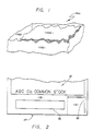
- Figure 1 is a partial cutaway perspective of a document with a storage medium thereon and specifically a magnetic stripe storage medium;
- Figure 2 is a top partial view of a document showing an area characterized by a uniqueness characteristic and a magnetic stripe storage medium;
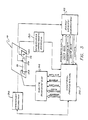
- Figure 3 is a simplified block diagram illustrating a system, including an optional write sub-system, in accordance with the invention;
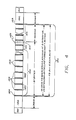
- Figure 4 is a pictorial representation of a bit string formatted for storage on a storage medium, such as a magnetic stripe, on a document;
- Figure 5 is a simplified block diagram showing a write subsystem such as that depicted in Figure 3;
- Figure 6A, 6B and 6C illustrate various waveforms, timing relationships and binary bit string data illustrating the operation of the authentication system in accordance with the invention;
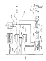
- Figure 7 is a simplified block diagram of a read subsystem useful in reading flux changes from a magnetic stripe;
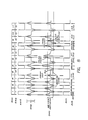
- Figure 8 is an illustration of various address, bit data, write and read signals at various locations in the authentication system of Figures 3, 5 and 7;
- Figure 9 is a series of waveforms illustrating the operation of the correlator and peak and polarity detector blocks of Figure 7;
- Figure 10 is a partial flow chart illustrating a means of recovering the number of data bits in a bit string and computation of data frame offsets, and
- Figure 11 is a flow chart illustrating one means of identifying the number and location of bits in a section of the bit string identified as containing erroneous bit values.
DETAILED DESCRIPTION
-
Although the present invention contemplates the use of various storage mediums on a document, the following detailed description is given with reference to a magnetic stripe as the preferred storage medium.
-
Referring initially to Figure 1, an item 100, such as a document made out of a fibrous medium 102 such as paper, has a surface 106 on which a magnetic stripe 104 is disposed such as by offset printing. The paper medium from which most documents of value such as stocks or bonds are made result in a highly irregular surface geometry. When a composition such as a magnetic ink is applied to such a surface to form a magnetic stripe, the resultant stripe assumes a similar irregular geometry. The magnetic stripe 104 consequently has a highly irregular geometry exhibiting a non-uniform magnetic flux characteristic along its length. Such a stripe is nevertheless the preferred authenticity verification storage medium for such documents of value.
-
Referring to Figure 2, the system in accordance with the invention comprises a printable item 10 made of paper or any other printable medium such as that described in conjunction with Figure 1. Matter readable by an observer such as words, designs pictorial representations and the like 12 may be printed across the surface of the document 10 using any desired method such as offset printing. For example, the printing may be such as to identify the document as a stock or bond, which may be of considerable monetary worth and indeed be a negotiable instrument. In order to provide additional protection against counterfeiting, a space 14 on the surface of the document 10 is set aside to define a field of sensing or sensible locations. A corner indicia 16 is positioned about the edge of the space 14 to define the space and enable alignment of a reader SO (Figure 3) with the space for subsequent repetitive reading of the uniqueness characteristic of the document such as in the manner set forth in U. S. Patent No. 4,423,415. The space 14 defines a specified area of the item which has, for example, a random but substantially non-changing transparency variation over its surface, and this random transparency establishes the machine-readable uniqueness characteristic in accordance with the teaching of U. S Patent No. 4,423,415. Once sensed, an identifier representative of the uniqueness characteristic is derived and assigned. Of course, any other uniqueness characteristic of the document which can be sensed and referenced by an identifier value, can be utilized without departing from the present invention.
-
The document 10 further includes a storage medium, which in the illustrated embodiment is a magnetic stripe 18 disposed over a portion of the irregular, random surface 19 of the document 10 by printing and preferably by offset printing. The magnetic stripe 18 will generally have non-uniform geometric and magnetic flux characteristics such as those described in conjunction with Figure 1.
-
Referring to Figure 3, a simplified block diagram of an authentication system in accordance with the invention includes the document 10 of Figure 2 having the magnetic stripe 18 to provide an escort memory of the document 10. In this authentication system, as illustrated, the uniqueness characteristic (such as transparency) is sensed from region 14 by a uniqueness-characteristic sensor 40. The uniqueness-characteristic reader 30 is coupled to the sensor 40 to receive a signal representative of the sensed uniqueness characteristic and therefrom define the identifier such as a binary number. Apparatus and methods for reading and deriving an identifier representative of the uniqueness characteristic are fully described in U.S. Patent No. 4,423,415, which patent is hereby incorporated by reference. A control processor 32 receives the identifier from the reader 30 and preferably encrypts the identifier and then processes the encrypted identifier to generate an error correction code for the encrypted identifier. In the preferred embodiment, the error correction code is a Bose-Chaudhure-Hocquenghem code whose derivation is fully described at page 269 et seq. in Error-Correcting Codes by Peterson and Weldon published by MIT Press. The encrypted identifier and the error correction code, both digitized, are combined with any other desired data, such as a public encryption key, to form a coded identifier.
-
Before being stored on the storage stripe, the coded identifier is formatted in accordance with a predefined format selected to facilitate authentication and data recovery. The result is a bit string which is sent to a write subsystem 34. The write subsystem 34 generates a "write current" signal 212 (Figure 6A) representative of the bit string 214 (Figure 6A). The write current signal 212 is provided to a write head 38 which, when positioned in close proximity to the magnetic stripe 18, will cause flux changes along the length of the stripe 18 as the stripe 18 moves past. In order to write the bits of the bit string 214 onto the stripe 18 at the correct location, a transport mechanism 36, under control of the control processor 32, causes the document 10 to physically pass beneath the write head 38 so that the write subsystem 34 will cause flux changes representative of individual bits in sequence to occur at predefined spacings along the magnetic stripe 18. A transport mechanism, useful in such a configuration, is described in the aforementioned U. S. Patent No. 4,423,415. Of course, the invention is equally applicable if the document 10 remains stationary and the write head 38 moves across the document.
-
To verify the authenticity of the document 10, the information stored on the magnetic stripe 18 is read as the document is moved by the transport mechanism 36 past a second head 39 under control of the control processor 32. The resultant signal (ideally appearing as the signal 228 of Figure 8 but in reality having the characteristics of signal 300 of Figure 8) is provided to a read/verify subsystem 42 which performs signal processing and correlation processing to recover a bit string which ideally would be the same as the bit string originally stored but in reality has both errors in the bit values and missing bits. The resultant read bit string signal 302 (Figure 8), in the form of time durations between peaks and peak polarity information, is then sent to the control processor 32 which applies local and global error correction algorithms in accordance with the invention to correct the remaining errors and thereby retrieve at least the encrypted identifier part of the bit string without error. The encrypted identifier is next decrypted in the control processor 32 to retrieve the identifier. The retrieved identifier is compared with a verification value from the reader 30 in the processor 32. If the retrieved identifier and the verification value match according to a predefined match criterion such as bit by bit identity, the document is verified as genuine.
-
The specific method of writing onto the magnetic stripe, reading data from the magnetic stripe and then processing the information to recapture missing or unreadable information will be described in greater detail hereafter.
-
Referring to Figure 4, the preferred format of the bit string 149 to be stored on the magnetic stripe 18 includes a leading edge 150 to allow automatic gain control (AGC) in a conventional manner, and a trailing edge 180 with a similar AGC to allow reading in either direction. The leading edge is a string or "1's" and trailing edge 180 preferably consists of a string of non-data characters referred to as framing characters. The number of "1's" in the leading edge and number of framing characters in the trailing edge is unimportant and may be any number sufficient to provide AGC. Following the leading edge 150 is a predefined sequence of bits, for example those represented by the 24 bit hexidecimal number FC0167 defined as a start sentinel 152. Following the start sentinel 152 is a data field 154 comprising a first framing character 153, an error correction code 162, a format designation coding 160, a public encryption key designation 158, the encrypted identifier 156, and a final framing character 164. Following the framing character 164 is a stop sentinel 166 which is a predefined and recognizable sequence of bits, for example, those represented by the 24 bit hexidecimal number 09D7FF.
-
In accordance with the invention, the data field 154 is divided by framing character 155 into equal subsections comprised of a predefined number of data bits, (e. g., 64 bits of data). Because (1) the number of data bits between framing characters is predefined, and (2) the bit time, that is, the time between flux changes representative of a " zero" and a "one" are known or can be determined, and (3) certain polarity conditions must exist in the sensed signal (for example, the magnetic flux change can only change from a positive to a negative or a negative to a positive, never a positive to a positive or a negative to a negative), correction of numerous local errors in individual bits can be performed. Even when the value of certain bits cannot be determined by such local error correction, the bit time, time between framing characters and polarity information enables the location of errors (their addresses in the bit string) and the number of missing or erroneous bits to be determined. This information is used in conjunction with the error correction codes to correct erroneous data or recover missing data in the bit string.
-
In a preferred embodiment of the invention, encryption of the identifier occurs using a private key while decryption is done using a public key. In accordance with the teaching of U.S. Patent No. 4,405,829, successful decryption according to the public key evidences the authenticity of the document by establishing that the document originated from a particular source since decryption using the public key designation would only be possible if encryption had occurred in accordance with a private key known only to the legitimate originator of the document.
-
Referring again to Figure 4, an illustrative data field format consists of 87 bytes which includes the encrypted identifier 156, the public key designation 158 and format designation 160, and 32 bytes of error correction code 162. The total of 119 bytes (952 bits) in the data field 154 are divided into data frames 168 consisting of 8 bytes (64 bits) of data. The start and stop sentinels 152 and 166, neither of which can have any nested framing characters, are each 24 bits in length. In accordance with error correcting theory, as set forth in the above book entitled Error-Correcting Codes, up to 16 bytes of missing data can be recovered in the bit string 149 provided the quantity of missing data can be determined. As previously described, the non-data framing characters, bit times and polarities are used to define the location and quantity of missing or erroneous data in a manner to be described hereafter.
-
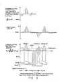
With further reference to the format of the bit string, the data in the bit string 149 can be generated and stored in a register as a series of "1"s and "0"s in a conventional manner. The register in the above illustration of Figure 4 would be 952 bits (storage locations) or 119 bytes long. Using the F2F convention for storing the data in such a register on a magnetic stripe, a single flux change within a predefined spacing along the magnetic stripe represents a "0" whereas two equally spaced flux changes within the same defined spacing would represent a "1". Stated differently, the value of each data bit may be represented by time periods between flux changes as the magnetic head 38 or 39 moves along the magnetic stripe 18 at a predefined speed. A "0" would be represented by a single time period (designated in chart 230 of Figure 6B as "t") whose value is determined by the bit density of the medium, the data sample rate, and the relative speed between the magnetic head (38 or 39) writing data onto or reading data from the stripe 18. A "1" would be represented by two consecutive time periods, each equal to 1/2 the duration of the time period of a "0" or 1/2 t (see time charts 303, Figure 8 and 230, Figure 6B). In the example of Figure 8, t is taken as 112 microseconds.
-
However, simply storing one data bit in one register location makes it impossible for the processor 32 to define framing characters digitally since framing characters are represented by flux changes at intermediate times between when a flux change, representative of a data bit, would occur. Referring to bit sequence 226 in Figure 6B and 214 in Figure 6A, the impossibility of distinguishing a non-data framing character from a data character, when each bit is represented by only one storage location, can be seen. To overcome this difficulty in accordance with the present invention, the processor 32 generates a binary bit string wherein each data bit is represented by eight "sub" bits (herein "binary bits") where a "0" is the sequence of binary bits 1000 0000 or 80 HEX and a "1" is the sequence of binary bits 1000 1000 or 88 HEX (see binary bit string 220 and its HEX representation 222 in Figure 6B). A framing character can then be defined by the 24 binary bit sequence (corresponding to three "0" data bit times) 1000 0000 0000 1000 0000 0000 or 80 08 00 HEX, so that flux changes generated at intermediate times can represent non-data information.
-
Since representation of flux changes as either data or non-data framing characters depends on the time spacing between flux changes, it can be seen from the time chart 230 of Figure 6B that the above binary bit representation results in the time period "t" between flux changes for a zero, two consecutive time periods t/2 for a one, and two consecutive time periods 3t/2 for a framing character. The octal representation 222 of the sequence of binary bits 220 representative of the bit string fragment 226 is therefore 80 08 00 88 80 80 88 88. As can now be appreciated, a "1" in the binary bit string 220 generated by the processor 32 (Figure 3) indicates not only that a flux change is to occur but also indicates when the flux change is to occur. Therefore, by writing the binary bit sequence 220 serially and at a predefined but constant rate, the time between each binary bit in the string 220, will be the same and the time duration between flux changes will indicate the value of the data stored or whether the information is a framing character. Of course, other storage conventions may be adopted without departing from the spirit of the invention in its broader aspects.
-
The use of eight binary bits also permits a degree of error tolerance in reading. For example, if instead of reading 80 HEX, the data read was 40 HEX, the processor could be programmed to still assign a "0" to that bit since 40 HEX should never occur and really indicates that the bit read was only displaced one binary bit position along the binary bit string.
-
Although the above bit and binary bit string formats have been illustrated with reference to certain specific characteristics, wide variations in the formatting of such bit strings are possible without departing from the spirit of the invention in its broadest aspects.
-
In order to store bit string 226 formatted in the manner described in conjunction with Figures 4 and 6B as flux changes at selected intervals along the magnetic stripe 18, the corresponding binary bit string 220 in Figure 6B, is provided from the control processor 32 to the write subsystem 34 (see Figure 3) which then causes magnetic flux variations to be applied along the length of the magnetic stripe where they are preserved for subsequent reading.
-
Referring to Figure 5 in conjunction with Figures 3, 6A, 6B and 6C the write subsystem 34 includes a frequency synthesizer 50 coupled to receive a write speed clock signal from the control processor 32. The write speed clock is a clock representative of the speed with which the transport mechanism 36 receives and passes the document 10 beneath the write head 38 or the write head 38 passes across the document 10. The frequency synthesizer 50 operates on the write speed clock and generates a synchronizing clock (SR clock) signal 204 which is coupled to a divide-by-8 circuit 52 and to a parallel-to-serial converter 54. The divide-by-8 circuit 52 generates identical load and increment signals 206 and 207, respectively. The increment signal 207 is coupled to a counter 56 and the load signal 206 is coupled the parallel-to-serial converter 54. The control processor 32, upon receiving appropriate signals from the transport mechanism 36 indicating proper alignment of the document and correct write speed in the transport mechanism 36, generates a "write enable" signal 240 and a "write window" signal 242 (figure 6C). The write enable signal 240 enables writing when the transport mechanism 36 indicates that the head 38 is over the magnetic stripe 18. As soon as a high write enable signal 240 occurs, the counter 56 is enabled and a switch 58 closed. The leading edge data 150 (Figure 4), which may consist of leading framing characters or leading ones, is then written onto the magnetic stripe 18 by the head 38 which causes flux changes to occur and remain impressed along the length of the magnetic stripe 18.
-
The write window signal 242 indicates the beginning of the start sentinel 152 and the end of the leading edge 150 and enables the counter 56 to increment beyond "2". More specifically, counter 56 increments on the increment signal 207 (Figure 6A) which occurs once every eighth SR clock pulse (204). Thus, the counter 56 increments for each eighth binary bit in the octal represented sequence 202 (222 in Figure 6B) received from the control processor 32. The count of the counter 56 and memory address data 200 (see also Figure 8) from the control processor 32 are coupled to a data memory 60 so as to store data in the proper storage location. The memory 60 is also coupled to the control processor 32 to receive data such as that illustrated by the octal sequence 202 (Figure 6A) or 222 (Figure 6B).
-
The data stored in the data memory 60 is provided to the parallel-to-serial converter 54 in groups of eight binary bits whenever a load pulse 206 occurs. The parallel-to-serial converter 54 then outputs the value of one binary bit string (8 binary bits) each time there is an SR clock pulse 204, with a flux changing pulse generated whenever there is a "1" in the binary bit being serially outputted. The resultant serial data signal 208 from the parallel-to-serial converter 54 is coupled to a toggle flipflop 62 to generate the write waveform 210 (224 in Figure 6B). The output from the toggle flipflop 62 is next coupled in sequence to a level shifter 64, the switch 58, a slope limiter 66 and a voltage-to-current converter and driver 68 to generate the write current 212 provided to the head 38. The level shifter 64 makes the waveform of the write current 212 symmetrical about ground potential with the slope limiter 66 controlling the rise and fall times.
-
Referring to Figure 7, in conjunction with Figures 3 and 8, the document 10 may be verified by inserting the document 10 into the transport mechanism 36 which causes the document 10 and the read head 39 to move relative to one another at a predefined rate under control of the control processor 32. As the document 10 passes the magnetic read head 39, flux changes previously impressed along the length of the magnetic stripe 18 are sensed causing an analog signal to be generated which ideally would look like signal 228 but in reality will look like an actual read signal 300. The signal 300 is coupled to an AGC amplifier 70. The output of the AGC amplifier 70 is coupled to a receiver pre-amplifier 72 and, optionally, a digital controlled gain amplifier 74. Referring momentarily to Figure 8 the "actual read" curve 300 illustrates a peak which occurs below a minimum peak detection threshold 301 and specifically identified as a "dropout". In certain instances, a significant increase in the retrieval of data will occur by either decreasing the threshold 301 or increasing the gain of the amplifier 74 so that the "dropout" peak in the actual read signal 300 will be detected as a peak and hence will not be lost. The control processor 32 supplies a gain register 76 with data through the data buss to control the gain of the digitally controlled gain amplifier 74.
-
The output of the amplifier 74 is next coupled to a low pass filter 78 which filters out high frequency noise, such as signal spikes, which would otherwise register as a flux change and hence indicate a false peak. The low pass filter therefore provides a means of additionally increasing the reliability of reading the flux changes stored on the magnetic stripe.
-
The output of the low pass filter 78 is coupled through a suitable conventional AC couple buffer amplifier 80 to an A to D converter 82 whereby the analog signal 300 (Figure 8) is sampled at predefined intervals to generate a digitized data signal 402 (Figure 9). The output of the A to D converter 82 is coupled to a correlator 84, with the objective being to identify the peaks in the signal 300 and thereby determine, as accurately as possible, the location of each flux change and the time between each peak, and whether that peak has a negative or a positive polarity.
-
The digitized signal 402 from the A to
D converter 82 is therefore coupled to the
correlator 84. Referring to Figure 9, the
correlator 84 applies an nth order correlator function 400 which in the present invention is selected to be approximately a cosine-squared function offset, so that:
where c
n is the correlator coefficient. A is zero for no DC response, but may be set to a small value so as to include some DC sensitivity.
-
In accordance with conventional correlator theory, the absolute value of the correlator or output, F
k, may be defined as:
where:
k is the sample number; and
m
n + k is the input sample.
This is illustrated at 404 in Figure 9.
-
The output 404 (Fk) of the correlator 84 is coupled to a peak and polarity detector 86 which defines a square wave 406 having a value "1" whenever the output of the correlator 84 is greater than a predefined threshold 405, and "0" whenever the output of the correlator 84 is below the threshold 405. Additionally, the peak and polarity detector 86 generates a sign-signal 408 (Figure 9) identifying the correlator output as either positive or negative. If the output 404 of the correlator 84 is positive, the sign-signal 408 is assigned the value "1", whereas if the output 404 is negative, the sign-signal is assigned the value "0".
-
In accordance with the invention, the midpoint of each square wave of the signal 406 (410 in Figure 9) is identified and coupled to generate a digital read signal 302 (Figure 8) in which each transition repre sents a midpoint (and hence a peak) in the signal 406. The data used by the control processor 32 is the polarity of each peak (transition in the read signal 302) and the time duration since the last peak (transition). To derive time duration and polarity information from the read signal 302, a memory 88, an address counter 90, switches 93 and 95 and an address decoder 92 are coupled, under the control of the control processor 32, to receive the digital read signal 302 and generate the time duration and polarity data which is stored in the memory 88 in byte format (herein "information byte") where each information byte represents the data for one peak i.e., one bit in the bit string. Each information byte has eight information bits and includes information bits indicating the polarity and state (peak or non-peak) several information bits (e.g., 6) set to represent the time duration as a number of predefined time increments such as 2.5 µsec. The data in the memory 88 is periodically sent to the control processor 32 via the data buss where the data is processed to correct errors in the bit string.
-
In accordance with the present invention, once the time between peaks (transitions) and the polarity signal information is provided to the central processor 32, a recovery process is applied so that a bit string with relatively few or no errors will take less execution time than bit string containing a significant number of errors.
-
The data recovery method according to the invention first considers the time duration between a peak and the previous peak and the polarity of each peak (i.e., each byte of information) individually. Only one of five conditions can occur resulting in a decision as to the value of a data bit represented by an information byte. The information byte and modifications to the information byte are then used to construct a second data buffer consisting of bits of the string being reconstructed. The five conditions and the resultant bits to be stored in the second buffer are as follows:
- 1. If the time duration of the information byte (time from the previous peak) is within limits determined by the control processor for a zero (i.e., equals a "zero bit time" ± an acceptable deviation), and the polarity of the information byte is opposite from that of the previous information byte, the bit represented by the information byte must be a zero and therefore a zero is stored for that bit in the second buffer.
- 2. If the time duration of the information byte is within the limits determined by the control processor for a zero, and the polarity is the same as that of the following information byte, a flux transition (peak) has been missed. This necessarily means that the data represented by the information byte is a one and therefore a one is stored in the second buffer in the address for that bit.
- 3. If the sum of the time duration of the current information byte and the time duration of the next information byte is within the bit time for a zero, and the polarities of the two information bytes are opposite, the bit value is necessarily a one and therefore a one is stored in the second buffer. If the bit is a "one", the following information byte is part of that "one" and therefore needs no further analysis and is skipped.
- 4. If the time duration of two consecutive information bytes are within the time duration specified for a framing character, and the information bytes have opposite polarities, a "2" is stored in the second buffer and an offset (see Figure 10) of each framing character in the buffer at that address is recorded for later use.
- 5. If the data value of an information byte is invalid (i.e., does not meet one of the above four conditions), for any reason, the actual value of the time duration information of the information byte is stored in the second buffer unless the actual value is less than 2 in which event a 3 is stored at the bit address of the second buffer.
-
During the above process, the control processor computes the mean bit time, that is, the time between peaks for a valid bit (whether 1 or 0) using an average of the 16 previous valid bit time frames. This mean bit time value is used as the basis for determining which condition 1-5 above is met by an information byte so as to identify data bits in the bit string as 0's, 1's, framing characters or errors.
-
The mean bit time value represents the speed that the magnetic stripe passes across the magnetic head. This speed, in the preferred embodiment, is not allowed to vary more than ± 10% from a nominal speed. Further, the determination of when a peak occurs in respect to the established mean bit time value in determining whether the data character is valid, is set at ± 12% for the writing and ± 25% for reading. Furthermore, when an invalid data value is detected, the actual bit time of each following information byte is stored in the second buffer until a "0" followed by two consecutive valid values (i.e., meet conditions 1, 2, or 3) or a framing character (condition 4) is detected.
-
Once the second data buffer has been constructed, the number of data bits in each data frame (8 bytes or 64 bits of data in the bit string) is determined. Since the number of data bits between framing characters is predefined and known, the contiguous, invalid data values (time duration values) are summed and divided by the bit time defined for a zero. The result is the number of missing bits. This information enables the error correcting codes to determine the value of data bits not otherwise corrected.
-
In accordance with a specific embodiment of the invention, the start sentinel is detected by shifting the data from the second buffer and comparing it with a predefined bit pattern for the start sentinel. If no more than a predefined number of bit errors occur, for example 2 bit errors, a match is deemed to have occurred. The location along the second buffer at which the last bit of the start sentinel occurred is then recorded for later use. The stop sentinel is similarly located with reference to a predefined bit pattern. The location of the first bit of the stop sentinel in the second buffer is similarly stored. Finally, the number of data bits between the stop and start sentinels is identified. Since the total number of data bits which should occur is known, this additional information can be utilized to further identify the number, location, and, in some instances, even derive the value of missing or erroneous data in the second buffer.
-
The start and end of the data to be recovered can be determined by the location of the last bit of the start sentinel, the first framing character and the number of bits between the start and stop sentinels. A flow chart illustrative of one technique for obtaining this information is illustrated in Figure 10.
-
In accordance with the preferred embodiment of the invention, there are 8 bytes of data (64 bits) between each framing character (herein referred to as a "frame of data"). Accordingly, the byte offset (referred to in condition number 4 above) of each frame of data in the recovered array in the second buffer is determined by the number of bits in each frame of data between the first and last valid frames. The offset of the first frame is determined in accordance with the flow chart of Figure 10. In accordance with the invention, the offsets for the remaining frames, once the offset for the first frame is determined, is in accordance with the equation:
Offset (n + 1) = Offset (n) + 8 * (bits (n)/72 + 1) where;
offset (n) is the byte offset in the recovered data array for frame n, and
bits (n) is the number of detected bits in frame n.
A frame length of 72 bits is used to compensate for inaccuracies in calculating the number of bits in each frame.
-
In accordance with further aspects of the invention, starting with the first valid frame, the data bits are packed into bytes in the recovered data bit string in the second buffer. A maximum of 64 bits of data are packed per frame of data until the last frame of data is formed. Buffer locations and recovered offsets of invalid data are recorded and all missing bits are packed as 1's. If any frame had an offset greater than 8 bytes from the previous frame, the data bits from the previous frame are packed into bytes starting from the end of the frame and moving in reverse. A maximum of 64 bits are packed for a missing frame. Information concerning invalid data is recorded, as previously described, with 1's.
-
In accordance with an illustrative embodiment of the invention, if the number of recovered data bits is greater than 888 but less than 1024, and less than 3 invalid areas in the data bit string were detected, error correction routines are executed with the message (bit string) length set to 119 bytes. If the number of recovered data bits is greater than 1024 and less than 3 invalid areas were detected, the error correction routines are executed with the message (bit string) length set to 144 bytes. If the error correction routines are unsuccessful, or the above conditions are not met, values stored in the invalid data areas are evaluated to determine the content. Since three valid data values are required to end an "invalid data area," the last two values in the invalid data area are valid. Therefore, the process begins at the end of the invalid data area (error area) and moves towards the start examining the data values individually. The flow chart for an illustrative means for performing this process is set forth in Figure 11.
-
Error correction routines using the error correction code are next executed with the message length set to 119 bytes if less than 1024 bit are recovered. Otherwise the message length is set to 144 bytes. If the error correction routines are unsuccessful, the bits in each invalid data area, except for the last two bits in each invalid data area, are inverted. The error correction routines are executed again with the message length unchanged. If the error correction routines are still unsuccessful, the message length is changed to the other set length, (that is 119 to 144 or 144 to 119), and the error correction routines are again executed. If the error correction routine are still unsuccessful, the data bits in each invalid data area are inverted to their original values and the error correction routines are executed with the message length unchanged. If the error correction routines are still unsuccessful, an error code is generated indicating that the document is not readable.
-
As previously indicated, various error correction codes are possible in accordance with the invention. However, in the preferred embodiment, error correction using the Bose-Chaudhuri-Hocquenghem codes as set forth in the Peterson and Weldon book entitled Error-Correcting Codes (Second Edition), published by the MIT Press and fully described at page 269 et seq, is preferred.
-
Once the originally stored encrypted identifier (verification value) has been recovered without error, it is decrypted and compared against a second identifier derived from the document's uniqueness characteristic. A positive correlation between them means the document is authentic.
-
Although the above description has been made with reference to the illustrative system of Figure 3 which includes both magnetic stripe reading and writing capabilities, passive reading systems without the write subsystem 34 or write head 38 are contemplated at most remote verification locations since writing capabilities would be unnecessary. Various other changes and modifications are also possible, including using a different storage medium, such as a bar code or other printed code pattern, without departing from the present invention.