EP0291167B1 - A code error detecting method - Google Patents
A code error detecting method Download PDFInfo
- Publication number
- EP0291167B1 EP0291167B1 EP88303249A EP88303249A EP0291167B1 EP 0291167 B1 EP0291167 B1 EP 0291167B1 EP 88303249 A EP88303249 A EP 88303249A EP 88303249 A EP88303249 A EP 88303249A EP 0291167 B1 EP0291167 B1 EP 0291167B1
- Authority
- EP
- European Patent Office
- Prior art keywords
- error
- polynomial
- symbols
- data
- code
- Prior art date
- Legal status (The legal status is an assumption and is not a legal conclusion. Google has not performed a legal analysis and makes no representation as to the accuracy of the status listed.)
- Expired - Lifetime
Links
Images


Classifications
-
- H—ELECTRICITY
- H03—ELECTRONIC CIRCUITRY
- H03M—CODING; DECODING; CODE CONVERSION IN GENERAL
- H03M13/00—Coding, decoding or code conversion, for error detection or error correction; Coding theory basic assumptions; Coding bounds; Error probability evaluation methods; Channel models; Simulation or testing of codes
- H03M13/03—Error detection or forward error correction by redundancy in data representation, i.e. code words containing more digits than the source words
- H03M13/05—Error detection or forward error correction by redundancy in data representation, i.e. code words containing more digits than the source words using block codes, i.e. a predetermined number of check bits joined to a predetermined number of information bits
- H03M13/13—Linear codes
- H03M13/15—Cyclic codes, i.e. cyclic shifts of codewords produce other codewords, e.g. codes defined by a generator polynomial, Bose-Chaudhuri-Hocquenghem [BCH] codes
-
- H—ELECTRICITY
- H03—ELECTRONIC CIRCUITRY
- H03M—CODING; DECODING; CODE CONVERSION IN GENERAL
- H03M13/00—Coding, decoding or code conversion, for error detection or error correction; Coding theory basic assumptions; Coding bounds; Error probability evaluation methods; Channel models; Simulation or testing of codes
- H03M13/03—Error detection or forward error correction by redundancy in data representation, i.e. code words containing more digits than the source words
- H03M13/05—Error detection or forward error correction by redundancy in data representation, i.e. code words containing more digits than the source words using block codes, i.e. a predetermined number of check bits joined to a predetermined number of information bits
- H03M13/09—Error detection only, e.g. using cyclic redundancy check [CRC] codes or single parity bit
Definitions
- the present invention relates to a code error detecting method which can be used for correcting data in a data file apparatus employing an optical disk of a write once type or an erasable type.
- optical disk having a characteristic capable of recording a great amount of data with a high recording density in a non-contact fashion has attracted attention in the field of memories including an auxiliary storage of a computer.
- data files of a write once type in which data can be only once additionally written and of an erasable type in which data can be rewritten as many times as necessary have been data files of a write once type in which data can be only once additionally written and of an erasable type in which data can be rewritten as many times as necessary.
- Efforts have been made for the development of recording methods as well as servo methods in various manufacturers and institutes.
- the optical disk In a data file using an optical disk, the optical disk has a diameter of 5 1/4 (5.25) or 3.5 inches and tracks in a concentric or spiral form with a track pitch of about 1.6 micrometers (am).
- a track is subdivided into a plurality of sectors constituting a circumference thereof such that a plurality of data items including symbols each comprising eight bits are written in the sector.
- a track includes 17 sectors, and the data capacity of each sector available for the user is 1024 bytes.
- the rotary speed of the disk is a constant angular speed of from about 1800 rpm to about 3600 rpm, and a semiconductor laser associated with a wavelength of about 830 nanometers (nm) is adopted as a light source.
- a light beam of which a light spot is focused to at most about 1 am data are recorded on the tracks in the form of projected or depressed portions (of the write once type) or according to directions of magnetization perpendicular to a disk surface of the optical disk (of the erasable type).
- the Reed-Solomon code is used in many cases in which the error correction can be achieved in byte unit and a lot of data can be corrected with reduced redundancy.
- the Reed-Solomon code enables error detection and correction to be efficiently accomplished, it has been known that mis-detection and mis-correction of an error occur with a certain probability.
- a sector of user data including 1024 symbols and control data symbols are arranged in a memory area to configure a rectangular form with 10 vertical symbols X 104 horizontal symbols in which four symbols including the last data symbol in the 104-th row are assigned as the parity data for the error check of the user data.
- the error check parity data of this example is generated as follows. First, ten data symbols in each column among the data symbols in byte units arranged in the first column through the 103th column are subjected to exclusive OR addition. Further, in the 104-th column, an exclusive OR addition of data of six symbols excepting the error check parity is performed, thereby generating, in total, 104 error check data in byte units.
- An error check information polynomial is constituted by the 104 data symbols in byte unit.
- the error check information polynomial is divided by a generator polynomial comprising four predetermined symbols of the Reed-Solomon code so as to use a residue or remainder resulting from the division as the error check parity and to assign the error check parity to the last four symbols in the 104-th column.
- This type of error detection method is known as the cyclic redundancy check code (CRC), and it is described in detail, for example, in Elwyn R. Berkelamp: “ALGEBRAIC CODING THEORY", Chapter 5, pages 119-145, McGraw-Hill Book Company and in W. Wesley Peterson and E. J. Weldon, Jr.: “ERROR-CORRECTING CODES", Second Edition, Chapter 8, pages 206-268.
- the data are arranged, like in the case of the recording operation, in the form having 10 vertical symbols x 104 horizontal symbols.
- an exclusive OR addition of data of ten symbols in each column is performed.
- an exclusive OR addition of data of six symbols excepting the symbols for the error check parity is performed.
- an error check information polynomial for the total 104 data symbols in byte unit is obtained.
- the information polynomial is divided by the generator polynomial used in the recording operation so as to obtain a residue or remainder.
- the generator polynomial differs, however, the Reed-Solomon code in byte unit of the same primitive polynomial is used, and hence various error detection methods can be considered by combining the error correction code with the CRC error detection code.
- the error detection method has not been presented. In general, the error detection is accomplished in the prior art example as follows.
- the reproduced data and the error correction parity are arranged in the form having ten vertical symbols x 120 horizontal symbols like in the recording operation, by using 16 parity data items additionally disposed in advance for the error correction of the data associated with 104 user data symbols in a horizontal row, a maximum of eight errors are corrected for each row, and, for each data in byte unit in a range from the first column to the 103rd column, an exclusive OR addition of ten symbols in each column is effected and an exclusive OR addition is effected on six symbol data excepting the error detectin parity in the 104-th column so as to obtain an error check information polynomial for the total 104 data symbols in byte unit.
- the information polynomial is divided by the same generator polynomial used in the recording operation so as to compare the residue with the error correction parity in the 104-th column. If the residue is equal to the parity, it is judged that there does not exist any error. Otherwise, the existence of an error is determined.
- the error detection method there has been adopted a method in which all data items are written in the memory during the reproducing operation as shown in FIG. 1 and thereafter an error correction processing is performed on the data such that the same error detection processing is effected when the data thus corrected are transferred to the user side, for example, a host computer.
- the error detection may be completed before the data are transferred to the user (host computer).
- a code error detecting method wherein, when symbol deta D i , j are arranged in the form including n vertical(column) symbols and m horizontal(row) symbols ,
- a code error detecting method wherein, when symbol data D i , j are arranged in the form including n vertical(column) symbols and m horizontal(row) symbols ,
- a code error detecting method wherein, when symbol deta D i , j are arranged in the form including n vertical(column) symbols and m horizontal(row) symbols ,
- One embodiment of the invention provides a method in which, in a recording operation, data including user data and control data representing addresses of an optical disk where the data are to be written is arranged in a form with n vertical symbols x m horizontal symbols, an addition is effected on exclusive OR results of n symbols in each vertical column ranging from the first column to the (m - 1 )-th column, and an addition is achieved on exclusive OR results of (n - t) symbols of the m-th column excepting t symbols including the last symbols, thereby establishing an information polynomial of data including the m symbols thus obtained.
- the information polynomial is then divided by a generator polynomial prepared beforehand for error detection and a residue obtained as a result of the division is arranged as an error detection parity in the t-byte location.
- a code error is found in the data of the m symbols of a horizontal row selected from the data constituted with n vertical symbols x m horizontal symbols or in data of (m - 1) symbols excepting the control data
- an error correction is accomplished by using an error correction code separately determined and a correction is carried out on the error detecting information polynomial for the data subjected to the error correction based on a location and a pattern associated with the error data obtained in the error correction, thereby detecting an error according to the result of the correction.
- FIG. 2 includes a host computer 1, an interface 2, a digital modulation circuit 3, a digital demodulation circuit 4, a sector buffer memory 5, an adder 6 for performing an addition of exclusive OR results of ten symbol data or 6 symbol data used in making code error check, a code error detection code (CRC) generator/checker 7, an error correction circuit 8, an encode/decode change-over switch 9, a data bus 10, an optical disk 11, and a temporary memory 12.
- a host computer 1 an interface 2
- a digital modulation circuit 3 for performing an addition of exclusive OR results of ten symbol data or 6 symbol data used in making code error check
- CRC code error detection code
- Di,j (0 ⁇ i 9, 0 ⁇ j ⁇ 103) designates user data and control data
- Ei,k (0 ⁇ k 15) denotes the error correction parity
- Cu (0 ⁇ u 3) indicates the error check parity
- Pv (0 ⁇ v 103) stands for data constituting an error check information polynomial
- Ri,s (0 ⁇ s 3) designates data constituting the residue polynomial of each row.
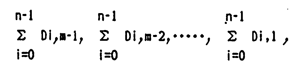
- the user data and control data Di,j are supplied as symbols in byte unit via the interface 2 and the data bus 10 to the sector buffer memory 5 in the order of D O , 103 , D 1,103 , D 2,103 , ... , D 9,103 , D O , 102 , ... Dg, 102 , ... , D 0,1 , D 1,1 , D 2,1, ..., D 9,1, D 0,0, D 1,0 , D 2,0, D 3,0, D 4 , o , and D5,o so as to be stored in the form with ten vertical symbols x 104 horizontal symbols as shown in FIG. 3.
- the data items are supplied to the adder circuit 6, which in turn effects an addition of exclusive OR results as follows.
- data items read from the optical disk 11 are demodulated by the digital demodulation circuit 4 and are supplied via the encode/decode switch 9 to the sector buffer memory 5.
- the data items are written therein in the form with ten vertical symbols x 120 horizontal symbols, like in the recording operation, as shown in FIG. 3.
- the data items are inputted to the adder 6, which then performs an addition of exclusive OR results as follows.
- the CRC generator/checker 7 which conducts a division thereof by a predetermined generator polynomial G(x) that has also been used in the recording operation.
- G(x) generator polynomial G(x) that has also been used in the recording operation.
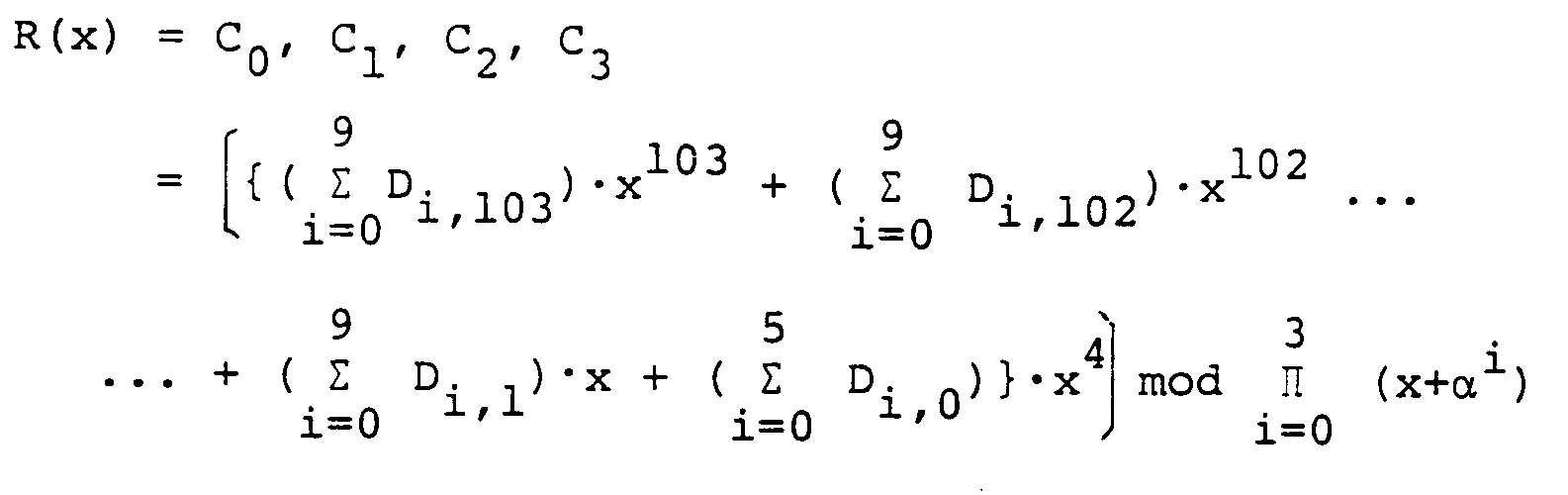
- the residue R(x) is attained as C 3 to Co, which are compared with the error correction parity R(x) subjected to the error correction, namely, C 3 to C0 read from the sector buffer memory 5 and supplied to the CRC generator/checker 7. If a matching condition results, the system determines that there does not exist any error. Otherwise, the existence of an error is assumed.
- the user data Di,j are transferred via the data bus 10 and the interface 2 to the host computer 1.
- an error message is transmitted to the host computer 1.
- the mark designates data that have been subjected to error correction in the reproducing operation, and the mark indicates data obtained through a computation after the error correction.
- the generator polynomial G(x) is in byte unit.
- the error check parity Cu is here computed so as to satisfy the following expression. or
- the residue is obtained in the same way as the conventional method on assumption that the 8 bit data including and are continuous bit streams, respectively, and then the result need only be divided into 8 bit units.
- the data items constituting the error check information polynomial are beforehand generated through an addition of exclusive OR results of the ten byte or 6 byte reproduction data in the column direction of FIG. 3 and thereafter by using the error location and the error pattern obtained during the error correction associated with each row, a correction is also effected on the data items constituting the information polynomical so as to accomplish the error detection.
- an error correction is first performed on data in an N-th row of FIG. 3, and an addition of exclusive OR results of the data of the N-th row thus corrected and the data of the (N + 1 )-th row not corrected is conducted for each symbol located in the same column so as to generate data items constituting a provisional information polynomial.
- the data D 0,103 is inputted to an input terminal of a syndrome generator and to an input terminal of an exclusive OR circuit.
- the resultant data are written again in the sector buffer memory 5 at the original address.
- Pu corresponding to the error location are read from the temporary memory 12 and are fed to the error correction circuit 8, which in turn effects an addition of exclusive OR results of the error pattern and the data of Pu thus read out, thereby performing the error correction.
- the resultant data are written again in the temporary memory 12 at the original address. Following this operation, for the data from the third row to the tenth row, the similar processing is repetitiously carried out.
- the data read from the optical disk 11 are written in the sector buffer memory 5, like in the recording operation, to form a shape constituted by ten vertical symbols x 120 horizontal symbols.
- the data and the error correction parity of the first horizontal row of the upper-most line of FIG. 3 including D 0,103 , D 0,102 , ... , D 0,0 , ⁇ 0,15 , ... , and E o , o are read from the sector buffer memory 5 and are then inputted to the error correction circuit 8, which in turn effects an error correction for the received data and parity.
- the corrected data are thereafter written again in the sector buffer memory 5 at the original address.
- the corrected data D 0,103 , D 0,102 , ... , and D 0,0 are read from the sector buffer memory 5 so as to be supplied to the CRC generator/checker 7, which divides the data by a predetermined generator polynomial G(x) to obtain a residue Ro(x), namely, D 0,3 , Co,2, D 0,1 , and D 0,0 to be stored in the temporary memory 12.
- a residue for each column namely, Ri(x) to Rs(x) including C 1,3 , C 1,2 , C 1,1 , C 1,0 , ... , C 5,3 , C 5,2 , C 5,1 , C 5,0 , which are then written in the temporary memory 12.
- the following expressions are obtained by assuming that the information polynomial and the generator polynomial of the first row of FIG. 3 are Mi(x) and G(x), respectively, and that the quotient polynomial and the residue polynomial obtained by dividing the information polynomial Mi(x) by the generator polynomial G(x) are Qi(x) and Ri(x), respectively.
- Rc(x) an addition of the data R 0 (x) to R 9 (x) is represented by Rc(x), namely, where,
- the error check parity namely, the residue polynomial of the first embodiment is expressed as follows.
- the third embodiment after the error correction is performed on the data of each horizontal row of FIG. 3 so as to obtain the error check parity of each horizontal row, an addition of exclusive OR results is effected for the error check parity obtained for each horizontal row so that the result of the addition is compared with the error check parity obtained in the recording operation, thereby detecting the presence or absence of the error. Consequently, a relatively long period of time is required to accomplish the computation.
- an embodiment for improving the above operation will be described.
- the data of a horizontal row of FIG. 3 are transferred from the sector buffer memory 5 to the error correction circuit 8, and then after the error correction is completed, the corrected data are written again in the sector buffer memory 5 at the original address. Subsequently, the data of the second row are transferred from the sector buffer memory 5 to the error correction circuit 8, and then after the error correction is completed, the corrected data are written again in the sector buffer memory 5 at the original address.
- a syndrome is computed by using the data first transferred from the sector buffer memory 5. Next, based on the syndrome thus obtained, the error location polynomial and error evaluator polynomial are computed so as to obtain the error location and the error pattern therefrom.
- Error data corresponding to the error location are read from the sector buffer memory 5 and then an addition of exclusive OR results is effected between the error data and the error pattern so as to perform the error correction, thereby writing again the corrected data in the sector buffer memory 5 at the original address.
- the sector buffer memory 5 is accessed only when the data of a horizontal row are transferred to the error correction circuit 8 to obtain the syndrome, when the error data are read out, and when the corrected data are rewritten. Namely, since the sector buffer memory 5 is not accessed when the error correction circuit 8 is computing the error location and the error pattern, this period of time is allocated to an operation to read from the sector buffer memory 5 the corrected data of the first row of FIG. 3 including D 0,103 , D 0,102 , ...
- the CRC generator/checker 7 the data items are subdivided by the generator polynomial G(x) and the residue R o (x) is obtained as C 0,3 , C 0,2 , C 0,1 , and Co,o so as to be written in the temporary memory 12.
- the error correction up to the tenth row is effected and C 1,3 , 6 1 , 2 , C 1,1 , C 1,0 , ... , C 8,3 , C 8,2 , C 8,1 and C 8,0 as the residues Ri(x) to C 8 (x) up to the ninth row are obtained, and they are written in the temporary memory 12.
- the corrected data items 6 9 , 103 , D 9,102 , ... , D 9,0 of the tenth row are read from the sector buffer memory 5 so as to be supplied to the CRC generator/checker 7.
- the residue R 3 (x) is obtained as 6 9 , 3 , 6 9 , 2 , 6 9 , 1 , and C 9,0 .
- the residues Ro(x) to R 3 (x) are read from the temporary memory and are then inputted to the error correction circuit 8, which performs an addition of exclusive OR results of the residues R 0 (x) to R 9 (x) to thereby obtain the final error check parity data ⁇ 3 , C 2 , C 1 , and C o .
- error check parity data are compared with the error check parity data C 3 , C 2 , C 1 , and C 0 which have been added to the 104-th column shown in Fig. 3 in the recording operation and for which error correction has been effected in the reproducing operation, thereby accomplishing the error detection.
- an error correction code system like that discussed in the present invention, which deals with an error correction code whose minimum inter-code distance is as great as 17, the processing to compute the error location and the error pattern requires relatively a long period of time. That is, the period of time associated with the processing above is sufficient for the system to read the data of a horizontal row from the sector buffer memory 5 and to transfer the data to the CRC generator/checker 7 so as to effect the processing.
- this method is of course applicable to the error check parity generation in the recording operation, if it is assumed that any error does not exist exactly in the reproducing operation.
Description
- The present invention relates to a code error detecting method which can be used for correcting data in a data file apparatus employing an optical disk of a write once type or an erasable type.
- Recently, an optical disk having a characteristic capable of recording a great amount of data with a high recording density in a non-contact fashion has attracted attention in the field of memories including an auxiliary storage of a computer. As an application of the optical disk, there have been data files of a write once type in which data can be only once additionally written and of an erasable type in which data can be rewritten as many times as necessary. Efforts have been made for the development of recording methods as well as servo methods in various manufacturers and institutes.
- In a data file using an optical disk, the optical disk has a diameter of 5 1/4 (5.25) or 3.5 inches and tracks in a concentric or spiral form with a track pitch of about 1.6 micrometers (am). A track is subdivided into a plurality of sectors constituting a circumference thereof such that a plurality of data items including symbols each comprising eight bits are written in the sector. For example, in a case of a 5.25 inch optical disk, there are disposed 18,750 tracks, a track includes 17 sectors, and the data capacity of each sector available for the user is 1024 bytes. In a data file having such an optical disk, the rotary speed of the disk is a constant angular speed of from about 1800 rpm to about 3600 rpm, and a semiconductor laser associated with a wavelength of about 830 nanometers (nm) is adopted as a light source. With a light beam of which a light spot is focused to at most about 1 am, data are recorded on the tracks in the form of projected or depressed portions (of the write once type) or according to directions of magnetization perpendicular to a disk surface of the optical disk (of the erasable type). In an operation to record or to reproduce data on or from the optical disks as described above, if there exists any dust, fingerprint, or damage on the disk surface, data cannot be correctly written thereon or data previously correctly written thereon cannot be appropriately read out therefrom in some cases, which is in general referred to as a code error. To cope with this code error, there are added redundant data, namely, parity data other than the data utilized by the user so as to detect a code error for error correction so that the correct data can be read even if such a code error takes place. In the data reproduction, with the error correction processing employing the above error correction code, the inherent code error data of 10-4 to 10-5 of reproduced data on an optical disk can be reduced to at most 10-12 after the error correction processing is effected. According to this method, there is developed the same performance as that of the hard disk conventionally used. In the data file employing an optical disk of this kind, since the minimum unit of data treated by the user is a byte, the Reed-Solomon code is used in many cases in which the error correction can be achieved in byte unit and a lot of data can be corrected with reduced redundancy. Although the Reed-Solomon code enables error detection and correction to be efficiently accomplished, it has been known that mis-detection and mis-correction of an error occur with a certain probability. Consequently, in order to increase the reliability of reproduced data with respect to the error, in addition to the error correction codes described above, there are added several bytes of error detection codes only for all data in a sector which can be used by the user, for example, 1024 bytes. The several bytes are almost ignorable as a redundancy measure. With the duplicated error detection countermeasurements, for example, even when mis-detection and mis-correction of an error occur in a error correction processing of the first stage, the code error can be appropriately detected by a code error detection processing of the second stage, thereby retaining high reliability.
- As an example of the data error correction and detection method for a data file employing the optical disk, the proposal under the title of "ENCODING SPECIFICATION FOR THE X3BI1-APPROVED EDAC CODE FOR 5 1/4 INCH OPTICAL STORAGE DEVICES", November 4, 1986 was submitted to the standardization committee for optical disk devices, ANSI X3BII.
- According to this method, in a recording operation, a sector of user data including 1024 symbols and control data symbols are arranged in a memory area to configure a rectangular form with 10 vertical symbols X 104 horizontal symbols in which four symbols including the last data symbol in the 104-th row are assigned as the parity data for the error check of the user data. The error check parity data of this example is generated as follows. First, ten data symbols in each column among the data symbols in byte units arranged in the first column through the 103th column are subjected to exclusive OR addition. Further, in the 104-th column, an exclusive OR addition of data of six symbols excepting the error check parity is performed, thereby generating, in total, 104 error check data in byte units. An error check information polynomial is constituted by the 104 data symbols in byte unit. The error check information polynomial is divided by a generator polynomial comprising four predetermined symbols of the Reed-Solomon code so as to use a residue or remainder resulting from the division as the error check parity and to assign the error check parity to the last four symbols in the 104-th column. This type of error detection method is known as the cyclic redundancy check code (CRC), and it is described in detail, for example, in Elwyn R. Berkelamp: "ALGEBRAIC CODING THEORY",
Chapter 5, pages 119-145, McGraw-Hill Book Company and in W. Wesley Peterson and E. J. Weldon, Jr.: "ERROR-CORRECTING CODES", Second Edition, Chapter 8, pages 206-268. - In the prior art example, in a reproducing operation, the data are arranged, like in the case of the recording operation, in the form having 10 vertical symbols x 104 horizontal symbols. In the respective data symbols in byte unit arranged in the first column through the 103rd column, an exclusive OR addition of data of ten symbols in each column is performed. In the 104-th column, an exclusive OR addition of data of six symbols excepting the symbols for the error check parity is performed. Thus, an error check information polynomial for the total 104 data symbols in byte unit is obtained. The information polynomial is divided by the generator polynomial used in the recording operation so as to obtain a residue or remainder. The remainder is then compared with the error detection parity of the 104-th column added in the recording operation and corrected in the reproducing operation, thereby detecting the presence or absence of the error. In this method, for the generation of the information polynomial, an exclusive OR addition of data of ten or six symbols in each column is performed. Consequently, there arises a disadvantage that even when a plurality of errors occur in the respective columns, there may possibly be obtained a result identical to the result computed when there does not exist any error. For example, even when two data items having the same bit constitution are included in a column and the same error occurs on bits located at the same positions of the respective data items, it is natural that the same result of the exclusive OR addition of ten symbols is attained for this column in this case and in a case where there does not exist any error in the data item. However, in the error correction method of the data file utilizing the otpical disk of this kind, there are provided error correction codes other than those adopted in the error detection method described above so as to correct an error of each data in advance, thereby greatly minimizing the chance of the operation in which the error described above is not appropriately detected. In the method of the prior art example, with respect to the error correction and the CRC error detection code, the generator polynomial differs, however, the Reed-Solomon code in byte unit of the same primitive polynomial is used, and hence various error detection methods can be considered by combining the error correction code with the CRC error detection code. In the proposal to ANSI X3BII already described, however, the error detection method has not been presented. In general, the error detection is accomplished in the prior art example as follows. Namely, as described above, in the reproducing operation, firstly, the reproduced data and the error correction parity are arranged in the form having ten vertical symbols x 120 horizontal symbols like in the recording operation, by using 16 parity data items additionally disposed in advance for the error correction of the data associated with 104 user data symbols in a horizontal row, a maximum of eight errors are corrected for each row, and, for each data in byte unit in a range from the first column to the 103rd column, an exclusive OR addition of ten symbols in each column is effected and an exclusive OR addition is effected on six symbol data excepting the error detectin parity in the 104-th column so as to obtain an error check information polynomial for the total 104 data symbols in byte unit. The information polynomial is divided by the same generator polynomial used in the recording operation so as to compare the residue with the error correction parity in the 104-th column. If the residue is equal to the parity, it is judged that there does not exist any error. Otherwise, the existence of an error is determined. As the error detection method, there has been adopted a method in which all data items are written in the memory during the reproducing operation as shown in FIG. 1 and thereafter an error correction processing is performed on the data such that the same error detection processing is effected when the data thus corrected are transferred to the user side, for example, a host computer.
- In this method, however, a result of the error detection is attained after all data items corrected are entirely transferred to the host computer, which causes a disadvantage in some cases.
- It is therefore an object of the present invention to provide an error detection method of detecting a code error which can be used in a data file employing an optical disk in which method, during a reproducing operation, an error location and an error pattern obtained in an error correction processing are used to correct the data constituting an information polynomial or a reception polynomial. The error detection may be completed before the data are transferred to the user (host computer).
- According to a first aspect of the present invention there is provided a code error detecting method, wherein
- an information polynomial of the i-th code word of n sets of Reed-Solomon codes constituted by m-(104) data symbols (Di,j), each of which is constituted by h binary bits, is denoted by Mi(x) = Di,m-1Xm-1 + + Di,0,
- a generator polynomial of t degree for t(4) error check parity symbols(co-c3) constituted by h binary bits is denoted by G(x),
- a quotient polynomial and a residue polynomial obtained by dividing the information polynomial Mi(x) by the generator polynomial G(x) are denoted by Qi(x) and Ri(x),respectively,
- respective degree terms (C3,C2,C1,C0) of the residue polynomial R(x) obtained by xt • M(x)/G(x) are inserted in the i = 0-degree position of the information polynomials Mi(x) of the code words of the n sets of Reed-Solomon codes, in the order of i = n-1,i = n-2,
and so forth sequentially from 0 degree term (g-m) = k error correction parity symbols E;,k being added to g code words in total, - the method characterised by comprising the following step during the reproducing operation:
- correcting reproduced information polynomials


- generating a quotient polynomial Qi(k) and a residue polynomial Ri(x) by dividing the corrected information polynomial

- exclusive OR adding the corrected information polynomials


- exclusive OR adding the residue polynomials


- generating a corrected residue polynomial


- a decision is made that there exists an error at least, if

- According to a second aspect of the present invention there is provided a code error detecting method, wherein, when symbol deta Di,j are arranged in the form including n vertical(column) symbols and m horizontal(row) symbols ,
- an information polynomial of the i-th code word of n sets of Reed-Solomon codes constituted by m-(104) data symbols (Di,j), each of which is constituted by h binary bits, is denoted by Mi(x) = Di,m-1Xm-1 + + Di,0 ,
- a generator polynomial of t degree for t(4) error check parity symbols(co-c3) constituted by h binary bits is denoted by G(x),
- a quotient polynomial and a residue polynomial obtained by dividing the information polynomial Mi(x) by the generator polynomial G(x) are denoted by Qi(x) and Ri(x),respectively,
- the result of an exclusive OR addition of the information polynomials Mi(x) is represented by

- the result of an exclusive OR addition of n vertical data symbols in respective columns from the first column to the (m-1)-th column is represented by


- the result of an exclusive OR addition of the residue polynomials Ri(x) is represented by

- respective degree terms (C3,C2,C1,C0) of the residue polynomial R(x) obtained by xt • M(x)/G(x) are inserted in the i = 0-degree position of the information polynomials Mi(x) of the code words of the n sets of Reed-Solomon codes, in the order of i = n-1, i = n-2,
and so forth sequentially from 0 degree term,- (g-m) = k error correction parity symbols E;,k being added to g code words in total,
- the method characterised by comprising the following step during the reproducing operation:
- an exclusive OR addition of n reproduced vertical data symbols in each of the columns from the first column to the (m-1)-th column is performed as represented by


- producing a reproduced information polynomial

- correcting the reproduced information polynomial

- symbols (E;,k) constituted by k Reed-Solomon codes performed in each n horizontal row, an exclusive OR addition of said error pattern and a data symbol corresponding to said error location in the reproduced information Polynomial M(x) resulting from the above exclusive OR additions is performed to effect correction of the reproduced information polynomial M(x);
- obtaining a residue polynomial R(x) by dividing


- a comparison is made between coefficients of respective degrees of the residue polynomial R(x) resulting from the division of the corrected information polynomial


- a decision is made that there exists an error at least, if coincidence does not occur in any one of the paired coefficients.
- According to a third aspect of the present invention there is provided a code error detecting method, wherein, when symbol data Di,j are arranged in the form including n vertical(column) symbols and m horizontal(row) symbols ,
- an information polynomial of the i-th code word of n sets of Reed-Solomon codes constituted by m-(104) data symbols (Di,j),each of which is constituted by h binary bits, is denoted by Mi(x) = Di,m-1Xm-1 + + Di,0 ,
- a generator polynomial of t degree for t(4) error check parity symbols(co-c3) constituted by h binary bits is denoted by G(x),
- a quotient polynomial and a residue polynomial obtained by dividing the information polynomial Mi(x) by the generator polynomial G(x) are denoted by Qi(x) and Ri(x),respectively,
- the result of an exclusive OR addition of the information polynomials Mi(x) is represented by

- the result of an exclusive OR addition of n vertical data symbols In respective columns from the first column to the (m-1)-th column is represented by

- the result of an exclusive OR addition of the residue polynomials Ri(x) is represented by

- respective degree terms (C3,C2,C1,C0) of the residue polynomial R(x) obtained by xt • M(x)/G(x) are inserted in the i = 0-degree position of the information polynomials Mi(x) of the code words of the n sets of Reed-Solomon codes, in the order of i = n-1,i = n-2,
and so forth sequentially from 0 degree term,- (g-m) = k error correction parity symbols E;,k being added to g code words in total,
- the method characterised by comprising the following step during the reproducing operation:
- producing a reproduced information polynomial

- correcting the reproduced information polynomial

- a comparison is made between coefficients of respective degrees of a residue polynomial


whereby a decision is made that there exists no error, if coincidence occurs between all paired coefficients, while - a decision is made that there exists an error at least,if coincidence does not occur in any one of the paired coefficients.
- According to a fourth aspect of the present invention there is provided a code error detecting method, wherein, when symbol deta Di,j are arranged in the form including n vertical(column) symbols and m horizontal(row) symbols ,
- an information polynomial of the i-th code word of n sets of Reed-Solomon codes constituted by m-(104) data symbols (Di,j), each of which is consituted by h binary bits, is denoted by Mi(x) = Di,m-1xm-1 + + Di,0 ,
- a generator polynomial of t degree for t(4) error check parity symbols(co-c3) constituted by h binary bits is denoted by G(x),
- a quotient polynomial and a residue polynomial obtained by dividing the information polynomial Mi(x) by the generator polynomial G(x) are denoted by Qi(x) and Ri(x),respectively,
- the result of an exclusive OR addition of the information polynomials Mi(x) is represented by

- the result of an exclusive OR addition of n vertical data symbols in respective columns from the first column to the (m-1)-th column is represented by


- the result of an exclusive OR addition of the residue polynomials Ri(x) is represented by

- respective degree terms (c3,c2,c1,c0) of the residue polynomial R(x) obtained by xt · M(x)/G(x) are inserted in the i = 0-degree position of the information polynomials Mi(x) of the code words of the n sets of Reed-Solomon codes, in the order of i = n-1,i = n-2,
and so forth sequentially from 0 degree term,- (g-m) = k error correction parity symbols Ei,k being added to g code words in total,
the method characterised by comprising the following step during the reproducing operation wherein error correction is made of the i-th code word in the code words of n sets of Reed-Solomon codes constituted by m data symbols and (g-m) = k error correction parity symbols: - a corrected information polynomial

- an information polynomial


- a decision is made that there exists an error at least,if

- One embodiment of the invention provides a method in which, in a recording operation, data including user data and control data representing addresses of an optical disk where the data are to be written is arranged in a form with n vertical symbols x m horizontal symbols, an addition is effected on exclusive OR results of n symbols in each vertical column ranging from the first column to the (m - 1 )-th column, and an addition is achieved on exclusive OR results of (n - t) symbols of the m-th column excepting t symbols including the last symbols, thereby establishing an information polynomial of data including the m symbols thus obtained. The information polynomial is then divided by a generator polynomial prepared beforehand for error detection and a residue obtained as a result of the division is arranged as an error detection parity in the t-byte location. In a reproducing operation, if a code error is found in the data of the m symbols of a horizontal row selected from the data constituted with n vertical symbols x m horizontal symbols or in data of (m - 1) symbols excepting the control data, an error correction is accomplished by using an error correction code separately determined and a correction is carried out on the error detecting information polynomial for the data subjected to the error correction based on a location and a pattern associated with the error data obtained in the error correction, thereby detecting an error according to the result of the correction.
- In the above configuration, when the error correction is completed on the data in a sector, a code error detection on the corrected data is also completed almost at the same time, and hence the code error detection can be carried out before the data are transferred to the user (host computer) and all processing can be completely effected within a period of time associated with the sector.
- The present invention will be apparent from the following detailed description taken in conjunction with the accompanying drawings in which:
- FIG. 1 is a block diagram showing a conventional system which performs code error detection on a data file using an optical disk;
- FIG. 2 is a block diagram showing a system of an embodiment of the present invention which performs code error detection on a data file using an optical disk; and
- FIG. 3 is an explanatory diagram showing a data arrangement for performing code error detection in an embodiment of the present invention.
- The illustration of FIG. 2 includes a host computer 1, an
interface 2, adigital modulation circuit 3, a digital demodulation circuit 4, asector buffer memory 5, an adder 6 for performing an addition of exclusive OR results of ten symbol data or 6 symbol data used in making code error check, a code error detection code (CRC) generator/checker 7, an error correction circuit 8, an encode/decode change-overswitch 9, adata bus 10, an optical disk 11, and atemporary memory 12. - Furthermore, in the data arrangement of FIG. 3, Di,j (0 ≦
i 9, 0 ≦ j < 103) designates user data and control data, Ei,k (0 ≧ k 15) denotes the error correction parity, Cu (0 ≦ u 3) indicates the error check parity, Pv (0 ≦ v 103) stands for data constituting an error check information polynomial, and Ri,s (0 ≦ s 3) designates data constituting the residue polynomial of each row. - The denotation of symbols used in the respective cases are shown hereunder by taking the error correction parity symbol C as an example:
- In the case of recording, "C" is used simply;
- in the case of reproducing, "C" is used;
- in the case of error correction, "C" is used; and
- in the case when obtained by calculation, "C" is used.
- First, in a recording operation, from the host computer 1, the user data and control data Di,j are supplied as symbols in byte unit via the
interface 2 and thedata bus 10 to thesector buffer memory 5 in the order of DO,103, D1,103, D2,103, ... , D9,103, DO,102, ... Dg,102, ... , D0,1, D1,1, D2,1, ..., D9,1, D0,0, D1,0, D2,0, D3,0, D4,o, and D5,o so as to be stored in the form with ten vertical symbols x 104 horizontal symbols as shown in FIG. 3. At the same time, the data items are supplied to the adder circuit 6, which in turn effects an addition of exclusive OR results as follows.


- These data items represented by Pv (0 ≦ v < 103) are inputted to the CRC generator/
checker 7 in the order of P103, P102, ... , Po so as to be divided by a predetermined four-symbol generator polynomial G(x). A residue R(x) resulting from the division is produced as error check parity data symbols C3 to Co, which are then written in thesector buffer memory 5. Subsequently, data items of a horizontal row including Do,j, D1,j, ... , D5,j (0 ≦ j ≦ 103); D6,j and C3,D7,j and C2, D8,j and C1, Dg,j and Co (1 ≦ j ≦ 103) are read out from the sector buffer so as to compute the error correction parity Ei,k in the error correction circuit 8 and the parity Ei,k is then written in thesector buffer memory 5. Finally, the data items of thesector buffer memory 5 are read out in the order of DO,103, D1,103, D 2,103, ... , D9,103, DO,102, D1,102, D2,102, ... , D9,102, ... , D0,1, D1,1, D2,1, ... , D9,1, Do,o, D1,0, D2,0, ... , D5,0, C3, C2, C1, Co, E0,15, E1,12, E2,15, ... , E9,15, EO,14, E1,14, E2,14, ... , Eg,14, ... , Eo,o, E1,0, E2,o, ... , Eg,o so as to be supplied via the encode/decode switch 9 to thedigital modulation circuit 3, which in turn adds signals such as a synchronization signal and records the resultant data items on the optical disk 11. - On the other hand, in a reproducing operation, data items read from the optical disk 11 are demodulated by the digital demodulation circuit 4 and are supplied via the encode/
decode switch 9 to thesector buffer memory 5. The data items are written therein in the form with ten vertical symbols x 120 horizontal symbols, like in the recording operation, as shown in FIG. 3. At the same time, the data items are inputted to the adder 6, which then performs an addition of exclusive OR results as follows.


- Where, indicates that the data bearing this mark appear in a reproducing operation. These data Pv (0 ≦ v ≦ 103) are written in a
temporary memory 12. Next, the data D0,j (0 ≦ j ≦ 103) and Eo,k (0 ≦ k 15) are sequentially read out in the direction from the left side to the right side in FIG. 3 and are supplied to the error correction circuit 8. In the error correction circuit 8, a location and a pattern of the error are computted. Then, data corresponding to the error location are read from thesector buffer memory 5 and are inputted to the error correction circuit 8. Thereafter, an addition of exclusive OR results is effected for the error pattern and the above data, and the resultant data are written again in thesector buffer memory 5 at the original address, thereby effecting the error correction. Subsequently, Pv corresponding to the error location is read from thetemporary memory 12 and is then supplied to the error correction circuit 8. An addition of exclusive OR results is effected for the error pattern and the above data, and the resultant data are written again in thetemporary memory 12 at the original address. Then, the above operation is repeated for i (1 ≦ i < 9) and thus it is repeated ten times in total. Finally, the data are read from thetemporary memory 12 in the order of P103, P102, ... , P,, and Po and are inputted to the CRC generator/checker 7, which conducts a division thereof by a predetermined generator polynomial G(x) that has also been used in the recording operation. An explanation of the marksoon follows. As a result, the residue R(x) is attained as C3 to Co, which are compared with the error correction parity R(x) subjected to the error correction, namely, C3 to C0 read from the
sector buffer memory 5 and supplied to the CRC generator/checker 7. If a matching condition results, the system determines that there does not exist any error. Otherwise, the existence of an error is assumed. When the error is not found in this judgement, from thesector buffer memory 5, the user data Di,j are transferred via thedata bus 10 and theinterface 2 to the host computer 1. When the error is assumed, an error message is transmitted to the host computer 1. In the above description, the markdesignates data that have been subjected to error correction in the reproducing operation, and the mark indicates data obtained through a computation after the error correction. In this case, as the generator polynomial G-(x) of the error check parity, the following is used when the primitive element of the finite field or Galois field obtained through a primitive polynomial m(x) = x8 + x4 + X 3 + x2 + 1 is assumed to be a.


- When using a binary-unit generator polynomial, the residue is obtained in the same way as the conventional method on assumption that the 8 bit data including


- In addition, in place of the operation as described above in which the error check parity R(x), namely, C3 to eo that are computed and are added in the recording operation and that are subjected to the error correction processing are compared with R(X), namely, R3 to Co attained through a computation in the reproducing operation so as to judge the presence or absence of the error, it is possible to supply the CRC generator/
checker 7 with Pu from thetemporary memory 12 and R(x) from thesector buffer memory 5 in the sequence of P103, P102, ... , Po, C3, C2, C1, and C0 so as to be divided by the generator polynomial G-(x), thereby determining the presence or absence of an error from the fact that the residue is not 0 or 0, respectively. - Next, a second embodiment of this invention will be explained.
- In the first embodiment, the data items constituting the error check information polynomial are beforehand generated through an addition of exclusive OR results of the ten byte or 6 byte reproduction data in the column direction of FIG. 3 and thereafter by using the error location and the error pattern obtained during the error correction associated with each row, a correction is also effected on the data items constituting the information polynomical so as to accomplish the error detection. In contrast with the first embodiment, according to the second embodiment, an error correction is first performed on data in an N-th row of FIG. 3, and an addition of exclusive OR results of the data of the N-th row thus corrected and the data of the (N + 1 )-th row not corrected is conducted for each symbol located in the same column so as to generate data items constituting a provisional information polynomial. Subsequently, error corrections are repeatedly performed on the data of the (N + 1 )-th row and the data items associated with the provisional information polynomial so as to effect a correction of the information polynomial, thereby carrying out the error detection. In this situation, the operation to record the data is the same as that of the first embodiment. In the recording operation, data read from the optical disk 11 are demodulated by the digital demodulation circuit 4 and are then written via the encode/decode change-over
switch 9 in thesector buffer memory 5 in the data arrangement, like in the recording operation, constituted by ten vertical symbols x 120 horizontal symbols as shown in FIG. 3. Next, the data and the error correction parity including D0,103, D0,102, ... , D0,0, Ê0,15, ... , and Eo,o of the upper-most row of FIG. 3 are read from thesector buffer memory 5 and are then supplied to the error correction circuit 8. At the same time, data items D0,103, D0,102, ... , and Do,o are written in thetemporary memory 12. In the error correction circuit 8, the location and the pattern of the error are computed for the error correction. Thereafter, the error data corresponding to the error location are read from thetemporary memory 12 and are delivered to the error correction circuit 8, which then effects an addition of exclusive OR results of the error pattern and the data thus read out, thereby performing the error correction. The resultant data are written again in thetemporary memory 12 at the original address. In this operation, in the error correction circuit 8, the data D0,103 is inputted to an input terminal of a syndrome generator and to an input terminal of an exclusive OR circuit. At the same time, the corrected data D0,103 is read from thetemporary memory 12 and is supplied to the other input teminal of the exclusive OR circuit of the error correction circuit 8, and then a computation of P103 = D0,102 0 D0,103 is accomplished, and the obtained data are written again in thetemporary memory 12 at the original address. Subsequently, in a similar way, while D0,102, D0,101, ... , and Do,o are sequentially supplied to the syndrome generator and the exclusive OR circuit, computations of P102 = D0,102 0 D0,102, P101 = D0,10, 0 D0,101, ... , and Po = Do,o + D0,0 are effected and the resultant data items are written again in thetemporary memory 12 at the respective original addresses. After these operations are completed, the error location and the error pattern are computed for the data and the error check parity in the second row of FIG. 3. Data corresponding to the error location are read from thesector buffer memory 5 and are then delivered to the error correction circuit 8, which in turn effects an addition of exclusive OR results of the error pattern and the data thus read out, thereby achieving the error correction. The resultant data are written again in thesector buffer memory 5 at the original address. Subsequently, Pu corresponding to the error location are read from thetemporary memory 12 and are fed to the error correction circuit 8, which in turn effects an addition of exclusive OR results of the error pattern and the data of Pu thus read out, thereby performing the error correction. The resultant data are written again in thetemporary memory 12 at the original address. Following this operation, for the data from the third row to the tenth row, the similar processing is repetitiously carried out. When the error correction and the correction of data items constituting the information polynomial for the CRC computation are completed for the data of tenth row, there are obtained in thetemporary memory 12 the data items constituting the information polynomial for the CRC computation which data items are identical to those of the first embodiment. - Next, a third embodiment of the present invention will be explained.
- In the third embodiment different from the first and second embodiments, in a reproducing operation, the data read from the optical disk 11 are written in the
sector buffer memory 5, like in the recording operation, to form a shape constituted by ten vertical symbols x 120 horizontal symbols. Next, the data and the error correction parity of the first horizontal row of the upper-most line of FIG. 3 including D0,103, D0,102, ... , D0,0, Ê0,15, ... , and Eo,o are read from thesector buffer memory 5 and are then inputted to the error correction circuit 8, which in turn effects an error correction for the received data and parity. The corrected data are thereafter written again in thesector buffer memory 5 at the original address. Subsequently, the corrected data D0,103, D0,102, ... , and D0,0 are read from thesector buffer memory 5 so as to be supplied to the CRC generator/checker 7, which divides the data by a predetermined generator polynomial G(x) to obtain a residue Ro(x), namely, D0,3, Co,2, D0,1, and D0,0to be stored in thetemporary memory 12. Similarly, for the rows ranging from the second row to the sixth row, there is obtained a residue for each column, namely, Ri(x) to Rs(x) including C1,3, C1,2, C1,1, C1,0, ... , C5,3, C5,2, C5,1, C5,0, which are then written in thetemporary memory 12. - In the almost similar fashion, the residue is obtained for each of the rows ranging from the seventh row to the tenth row, which is different from that of each of the rows ranging from the first row to the sixth row. Namely, as can be seen from FIG. 3, the number of data items of each row is smaller than that of each row associated with the rows ranging from the first row to the sixth row by one symbol and hence the computation is carried out on assumption that 0 data exists in that location. In this fashion, there are obtained the residues R6(x) - R9 (x), namely, C6,3, C6,2, C6,1, C6,0 to C9,3, C9,2, C9,1, C9,0. Finally, an addition of the exclusive OR results is effected on R0(x) to Rg(x) as follows.


- It is necessary here to prove that the residues of the first and second embodiments are equal to those of the third embodiment. For simplification of the description, it is assumed that there does not exist any error in a reproducing operation. Naturally, the essential properties are not lost by the above assumption.
- In the embodiment of FIG. 3, the following expressions are obtained by assuming that the information polynomial and the generator polynomial of the first row of FIG. 3 are Mi(x) and G(x), respectively, and that the quotient polynomial and the residue polynomial obtained by dividing the information polynomial Mi(x) by the generator polynomial G(x) are Qi(x) and Ri(x), respectively.


- Assume here that an addition of the data R0(x) to R9(x) is represented by Rc(x), namely,

where,


- Here, the following relationship is satisfied in the first embodiment.


- Let us check whether or not Rc(x) = RD(x) is satisfied.

- Assuming here that G(x) is a polynomial of t degree, the expression on the left side is a polynomial of t-1 degree at most. On the other hand, if


- According to the third embodiment, after the error correction is performed on the data of each horizontal row of FIG. 3 so as to obtain the error check parity of each horizontal row, an addition of exclusive OR results is effected for the error check parity obtained for each horizontal row so that the result of the addition is compared with the error check parity obtained in the recording operation, thereby detecting the presence or absence of the error. Consequently, a relatively long period of time is required to accomplish the computation. Next, an embodiment for improving the above operation will be described.
- In this embodiment, the data of a horizontal row of FIG. 3 are transferred from the
sector buffer memory 5 to the error correction circuit 8, and then after the error correction is completed, the corrected data are written again in thesector buffer memory 5 at the original address. Subsequently, the data of the second row are transferred from thesector buffer memory 5 to the error correction circuit 8, and then after the error correction is completed, the corrected data are written again in thesector buffer memory 5 at the original address. According to the error correction procedure in this embodiment, a syndrome is computed by using the data first transferred from thesector buffer memory 5. Next, based on the syndrome thus obtained, the error location polynomial and error evaluator polynomial are computed so as to obtain the error location and the error pattern therefrom. Error data corresponding to the error location are read from thesector buffer memory 5 and then an addition of exclusive OR results is effected between the error data and the error pattern so as to perform the error correction, thereby writing again the corrected data in thesector buffer memory 5 at the original address. In this operation, thesector buffer memory 5 is accessed only when the data of a horizontal row are transferred to the error correction circuit 8 to obtain the syndrome, when the error data are read out, and when the corrected data are rewritten. Namely, since thesector buffer memory 5 is not accessed when the error correction circuit 8 is computing the error location and the error pattern, this period of time is allocated to an operation to read from thesector buffer memory 5 the corrected data of the first row of FIG. 3 including D0,103, D0,102, ... , and 60,0, which are then inputted to the CRC generator/checker 7. In the CRC generator/checker 7, the data items are subdivided by the generator polynomial G(x) and the residue Ro(x) is obtained as C0,3, C0,2, C0,1, and Co,o so as to be written in thetemporary memory 12. In the similar fashion, the error correction up to the tenth row is effected and C1,3, 61,2, C1,1, C1,0, ... , C8,3, C8,2, C8,1 and C8,0 as the residues Ri(x) to C8(x) up to the ninth row are obtained, and they are written in thetemporary memory 12. - Finally, the corrected data items 69,103, D9,102, ... , D9,0 of the tenth row are read from the
sector buffer memory 5 so as to be supplied to the CRC generator/checker 7. In the CRC generator/checker 7, the residue R3(x) is obtained as 69,3, 69,2, 69,1, and C9,0. Next, the residues Ro(x) to R3(x) are read from the temporary memory and are then inputted to the error correction circuit 8, which performs an addition of exclusive OR results of the residues R0(x) to R9(x) to thereby obtain the final error check parity data ë3, C2, C1, and Co. These error check parity data are compared with the error check parity data C3, C2, C1, and C0 which have been added to the 104-th column shown in Fig. 3 in the recording operation and for which error correction has been effected in the reproducing operation, thereby accomplishing the error detection. In an error correction code system, like that discussed in the present invention, which deals with an error correction code whose minimum inter-code distance is as great as 17, the processing to compute the error location and the error pattern requires relatively a long period of time. That is, the period of time associated with the processing above is sufficient for the system to read the data of a horizontal row from thesector buffer memory 5 and to transfer the data to the CRC generator/checker 7 so as to effect the processing. Furthermore, this method is of course applicable to the error check parity generation in the recording operation, if it is assumed that any error does not exist exactly in the reproducing operation. - Now, as already described with respect to the prior art example, in the method of producing an information polynomial by performing an addition of exclusive OR results of ten vertical symbols in each column among the data arranged in the form having ten vertical symbols and 104 horizontal symbols, if an even number of errors should occur at the same bit positions of the data having the same bit structure in a column, an addition of exclusive OR results of the ten vertical symbols in the column becomes completely identical to that obtained when there exists no error. Similarly, in an error detection method in which error correction is performed for each horizontal row so as to obtain an information polynomial by using data resulting therefrom, the information polynomial thus obtained is then divided by a generator polynomial to obtain a residue polynomial for each row, and finally the residue polynomials for respective rows are added together to effect error detection, for example, if all data in two rows are identical with each other and identical errors should occur at the same positions thereof, the two resultant residue polynomials become completely identical with each other, namely, an addition of exclusive OR results therefrom becomes identical to that obtained when there does not exist any error. In these cases, it results that the existence of such errors is overlooked. Although it is considered that such cases stand generally with low probability, if two separate code error detection methods are used in parallel to decide the existence of an error and if the existence of an error is detected by any one of the two methods, it is possible to assure high reliability.
the result of an exclusive OR addition of the information polynomials Mi(x) is represented by


whereby a decision is made that there exists no error , if
Claims (12)


and so forth sequentially from 0 degree term


whereby a decision is made that there exists no error , if


symbols (Ei,k) constituted by k Reed-Solomon codes performed in each n horizontal row, an exclusive OR addition of said error pattern and a data symbol corresponding to said error location in the reproduced information polynomial M(x) resulting from the above exclusive OR additions is performed to effect correction of the reproduced information polynomial M(x);


whereby a decision is made that there exists no error, if coincidence occurs between all paired coefficients, while,


and so forth sequentially from 0 degree term,

wherein an exclusive OR addition is effected between data of the i-th row, which have been corrected, and data of the (i+1)-th row which have not yet been corrected, both in the same column, so as to produce data constituting a provisional information polynomial, and in accordance with an error location and an error pattern obtained through error correction of the data of (i+1)-th row, an exclusive OR addition of said error pattern and data symbol of tee provisional information polynomial corresponding to said error location is made so as to effect correction of the reproduced information polynomial M(x), the above processing being repeated; and
whereby a decision is made that there exists no error, if coincidence occurs between all paired coefficients, while


and so forth sequentially from 0 degree term,
the method characterised by comprising the following step during the reproducing operation wherein error correction is made of the i-th code word in the code words of n sets of Reed-Solomon codes constituted by m data symbols and (g-m) = k error correction parity symbols:

the generator polynomial of h·t degree constituted by binary bits is used, and when a residue polynomial is expressed by
Applications Claiming Priority (4)
| Application Number | Priority Date | Filing Date | Title |
|---|---|---|---|
| JP91341/87 | 1987-04-14 | ||
| JP9134187A JPS63255876A (en) | 1987-04-14 | 1987-04-14 | Method for detecting code error |
| JP92526/87 | 1987-04-15 | ||
| JP9252687A JPS63257966A (en) | 1987-04-15 | 1987-04-15 | Method for detecting code error |
Publications (3)
| Publication Number | Publication Date |
|---|---|
| EP0291167A2 EP0291167A2 (en) | 1988-11-17 |
| EP0291167A3 EP0291167A3 (en) | 1990-09-05 |
| EP0291167B1 true EP0291167B1 (en) | 1994-01-19 |
Family
ID=26432793
Family Applications (1)
| Application Number | Title | Priority Date | Filing Date |
|---|---|---|---|
| EP88303249A Expired - Lifetime EP0291167B1 (en) | 1987-04-14 | 1988-04-12 | A code error detecting method |
Country Status (3)
| Country | Link |
|---|---|
| US (1) | US4949342A (en) |
| EP (1) | EP0291167B1 (en) |
| DE (1) | DE3887200T2 (en) |
Cited By (2)
| Publication number | Priority date | Publication date | Assignee | Title |
|---|---|---|---|---|
| US7907460B2 (en) | 2001-10-11 | 2011-03-15 | Altera Corporation | Error detection on programmable logic resources |
| US8112678B1 (en) | 2004-01-27 | 2012-02-07 | Altera Corporation | Error correction for programmable logic integrated circuits |
Families Citing this family (58)
| Publication number | Priority date | Publication date | Assignee | Title |
|---|---|---|---|---|
| JP2695195B2 (en) * | 1988-09-02 | 1997-12-24 | 三菱電機株式会社 | Error correction circuit |
| JPH02105730A (en) * | 1988-10-14 | 1990-04-18 | Sony Corp | Data recording method |
| US5140596A (en) * | 1990-02-20 | 1992-08-18 | Eastman Kodak Company | High speed encoder for non-systematic codes |
| DE69114788T2 (en) * | 1990-08-29 | 1996-07-11 | Honeywell Inc | Data transmission system with checksum computing means. |
| US5267248A (en) * | 1990-12-24 | 1993-11-30 | Eastman Kodak Company | Method and apparatus for selecting an optimum error correction routine |
| JP2915583B2 (en) * | 1991-01-14 | 1999-07-05 | キヤノン株式会社 | Image recording device |
| JPH05158722A (en) * | 1991-12-10 | 1993-06-25 | Hitachi Ltd | Error detection/correction system |
| JP2672916B2 (en) * | 1991-12-13 | 1997-11-05 | 富士通株式会社 | Data check method for array disk device |
| JPH05265939A (en) * | 1992-03-23 | 1993-10-15 | Toshiba Corp | Data transfer equipment |
| JP3259323B2 (en) * | 1992-04-13 | 2002-02-25 | ソニー株式会社 | De-interleave circuit |
| EP0571019B1 (en) * | 1992-05-19 | 2000-01-26 | Koninklijke Philips Electronics N.V. | Extended error protected communication system |
| JP2821324B2 (en) * | 1992-11-04 | 1998-11-05 | 三菱電機株式会社 | Error correction circuit |
| JP3000811B2 (en) * | 1993-01-25 | 2000-01-17 | 日本電気株式会社 | Cyclic coding and CRC device and processing method thereof |
| US5553088A (en) * | 1993-07-02 | 1996-09-03 | Deutsche Forschungsanstalt Fuer Luft- Und Raumfahrt E.V. | Laser amplifying system |
| US5629949A (en) * | 1993-09-21 | 1997-05-13 | Cirrus Logic, Inc. | Error correction verification method and apparatus using CRC check remainders |
| US5602857A (en) * | 1993-09-21 | 1997-02-11 | Cirrus Logic, Inc. | Error correction method and apparatus |
| US5592498A (en) * | 1994-09-16 | 1997-01-07 | Cirrus Logic, Inc. | CRC/EDC checker system |
| JPH08106733A (en) * | 1994-10-07 | 1996-04-23 | Hitachi Ltd | Information storage-medium utilization system |
| US5774648A (en) * | 1996-10-02 | 1998-06-30 | Mitsubishi Semiconductor Of America, Inc. | Address generator for error control system |
| DE69731932T2 (en) * | 1996-10-29 | 2006-02-16 | International Business Machines Corp. | Method and apparatus for two-stage CRC-32 calculation |
| JP3430193B2 (en) * | 1997-01-20 | 2003-07-28 | 株式会社日立製作所 | Digital signal reproducing apparatus and digital signal reproducing method |
| US6092231A (en) * | 1998-06-12 | 2000-07-18 | Qlogic Corporation | Circuit and method for rapid checking of error correction codes using cyclic redundancy check |
| US6304993B1 (en) | 1998-12-14 | 2001-10-16 | Lsi Logic Corporation | Method and apparatus for performing efficient reseeks in an optical storage device |
| EP1146651A1 (en) * | 2000-04-10 | 2001-10-17 | Hewlett-Packard Company | Error detection for data storage and transmission |
| EP1146650A1 (en) * | 2000-04-10 | 2001-10-17 | Hewlett-Packard Company, A Delaware Corporation | Error detection for data storage and transmission |
| JP3752995B2 (en) * | 2000-09-27 | 2006-03-08 | 日本ビクター株式会社 | Information recording / reproducing device |
| US7047479B1 (en) | 2002-02-04 | 2006-05-16 | Cypress Semiconductor Corp. | Parallel CRC formulation |
| US7111228B1 (en) | 2002-05-07 | 2006-09-19 | Marvell International Ltd. | System and method for performing parity checks in disk storage system |
| US7114116B2 (en) * | 2002-09-13 | 2006-09-26 | Sun Microsystems, Inc. | Accelerated Galois data integrity crosscheck system and method |
| US7007114B1 (en) | 2003-01-31 | 2006-02-28 | Qlogic Corporation | System and method for padding data blocks and/or removing padding from data blocks in storage controllers |
| US7287102B1 (en) | 2003-01-31 | 2007-10-23 | Marvell International Ltd. | System and method for concatenating data |
| US7492545B1 (en) | 2003-03-10 | 2009-02-17 | Marvell International Ltd. | Method and system for automatic time base adjustment for disk drive servo controllers |
| US7039771B1 (en) | 2003-03-10 | 2006-05-02 | Marvell International Ltd. | Method and system for supporting multiple external serial port devices using a serial port controller in embedded disk controllers |
| US7870346B2 (en) | 2003-03-10 | 2011-01-11 | Marvell International Ltd. | Servo controller interface module for embedded disk controllers |
| US7064915B1 (en) | 2003-03-10 | 2006-06-20 | Marvell International Ltd. | Method and system for collecting servo field data from programmable devices in embedded disk controllers |
| US7219182B2 (en) | 2003-03-10 | 2007-05-15 | Marvell International Ltd. | Method and system for using an external bus controller in embedded disk controllers |
| US7526691B1 (en) | 2003-10-15 | 2009-04-28 | Marvell International Ltd. | System and method for using TAP controllers |
| US7188296B1 (en) | 2003-10-30 | 2007-03-06 | Sun Microsystems, Inc. | ECC for component failures using Galois fields |
| US7139150B2 (en) | 2004-02-10 | 2006-11-21 | Marvell International Ltd. | Method and system for head position control in embedded disk drive controllers |
| JP4135680B2 (en) * | 2004-05-31 | 2008-08-20 | ソニー株式会社 | Semiconductor memory device and signal processing system |
| US7120084B2 (en) | 2004-06-14 | 2006-10-10 | Marvell International Ltd. | Integrated memory controller |
| US8166217B2 (en) | 2004-06-28 | 2012-04-24 | Marvell International Ltd. | System and method for reading and writing data using storage controllers |
| US7757009B2 (en) | 2004-07-19 | 2010-07-13 | Marvell International Ltd. | Storage controllers with dynamic WWN storage modules and methods for managing data and connections between a host and a storage device |
| US8032674B2 (en) * | 2004-07-19 | 2011-10-04 | Marvell International Ltd. | System and method for controlling buffer memory overflow and underflow conditions in storage controllers |
| US9201599B2 (en) | 2004-07-19 | 2015-12-01 | Marvell International Ltd. | System and method for transmitting data in storage controllers |
| US7386661B2 (en) | 2004-10-13 | 2008-06-10 | Marvell International Ltd. | Power save module for storage controllers |
| US7240267B2 (en) | 2004-11-08 | 2007-07-03 | Marvell International Ltd. | System and method for conducting BIST operations |
| US7802026B2 (en) * | 2004-11-15 | 2010-09-21 | Marvell International Ltd. | Method and system for processing frames in storage controllers |
| US20060168499A1 (en) * | 2005-01-27 | 2006-07-27 | Edwards Jathan D | Data archive verify software |
| US7609468B2 (en) * | 2005-04-06 | 2009-10-27 | Marvell International Ltd. | Method and system for read gate timing control for storage controllers |
| JP2006323434A (en) * | 2005-05-17 | 2006-11-30 | Nec Corp | Data processor and memory correction method therefor |
| TW200643703A (en) * | 2005-06-06 | 2006-12-16 | Novatek Microelectronics Corp | Architecture and method for error detection and correction for data transmitted in a network |
| US7844886B1 (en) * | 2006-05-16 | 2010-11-30 | Altera Corporation | Parallel processing error detection and location circuitry for configuration random-access memory |
| US7634713B1 (en) * | 2006-05-16 | 2009-12-15 | Altera Corporation | Error detection and location circuitry for configuration random-access memory |
| JP2008159198A (en) * | 2006-12-26 | 2008-07-10 | Nec Electronics Corp | Error correction apparatus and recording and playback apparatus |
| KR20140146275A (en) * | 2013-06-14 | 2014-12-26 | 삼성전자주식회사 | Operating method for memory controller controlling nonvolatile memory device and nonvolatile memroy system |
| US9417957B2 (en) * | 2013-10-04 | 2016-08-16 | Infineon Technologies Ag | Method of detecting bit errors, an electronic circuit for detecting bit errors, and a data storage device |
| TWI564904B (en) * | 2014-05-13 | 2017-01-01 | 群聯電子股份有限公司 | Data managing method, memory control circuit unit and memory storage apparatus |
Family Cites Families (5)
| Publication number | Priority date | Publication date | Assignee | Title |
|---|---|---|---|---|
| CA1180451A (en) * | 1981-04-16 | 1985-01-02 | Sony Corporation | Method for coding an error correcting code |
| US4532517A (en) * | 1983-02-28 | 1985-07-30 | Allied Corporation | Cyclic redundancy check monitor for microwave landing system beam steering unit |
| US4564945A (en) * | 1983-06-20 | 1986-01-14 | Reference Technology, Inc. | Error-correction code for digital data on video disc |
| US4633471A (en) * | 1983-09-19 | 1986-12-30 | Storage Technology Partners Ii | Error detection and correction in an optical storage system |
| NL8400629A (en) * | 1984-02-29 | 1985-09-16 | Philips Nv | QUICK DECODE FOR REED-SOLOMON CODES, WHICH CAN ALSO BE USED AS ENCODEUR AND RECORDING / REPRODUCTION DEVICE WITH SUCH AN ENCODE / DECODEUR. |
-
1988
- 1988-04-11 US US07/180,063 patent/US4949342A/en not_active Expired - Fee Related
- 1988-04-12 EP EP88303249A patent/EP0291167B1/en not_active Expired - Lifetime
- 1988-04-12 DE DE88303249T patent/DE3887200T2/en not_active Expired - Fee Related
Cited By (3)
| Publication number | Priority date | Publication date | Assignee | Title |
|---|---|---|---|---|
| US7907460B2 (en) | 2001-10-11 | 2011-03-15 | Altera Corporation | Error detection on programmable logic resources |
| US8130574B2 (en) | 2001-10-11 | 2012-03-06 | Altera Corporation | Error detection on programmable logic resources |
| US8112678B1 (en) | 2004-01-27 | 2012-02-07 | Altera Corporation | Error correction for programmable logic integrated circuits |
Also Published As
| Publication number | Publication date |
|---|---|
| DE3887200D1 (en) | 1994-03-03 |
| US4949342A (en) | 1990-08-14 |
| EP0291167A3 (en) | 1990-09-05 |
| EP0291167A2 (en) | 1988-11-17 |
| DE3887200T2 (en) | 1994-05-05 |
Similar Documents
| Publication | Publication Date | Title |
|---|---|---|
| EP0291167B1 (en) | A code error detecting method | |
| US6553533B2 (en) | Method and apparatus for detecting and correcting errors and erasures in product ECC-coded data arrays for DVD and similar storage subsystems | |
| US4881232A (en) | Method and apparatus for error correction | |
| US6158038A (en) | Method and apparatus for correcting data errors | |
| US4564945A (en) | Error-correction code for digital data on video disc | |
| KR100517482B1 (en) | Concurrent row/column syndrome generator for a product code | |
| US6003151A (en) | Error correction and detection system for mass storage controller | |
| US6751771B2 (en) | Method and apparatus for error processing in optical disk memories | |
| US6470473B1 (en) | Data decoding processing system and method | |
| US4604748A (en) | Data processing system with error correction | |
| US8281225B2 (en) | Digital data coding and recording apparatus, and method of using the same | |
| IE71652B1 (en) | Byte write error method and apparatus | |
| JPH01307057A (en) | Method and apparatus for encoding and mapping sector address of magnetic disc | |
| EP1048034B1 (en) | Methods and apparatus for data storage on magnetic media including error correction codes | |
| JP2005500730A (en) | Improved coding when information is provided to the decoder | |
| US20070204188A1 (en) | Error correction method and reproduction apparatus | |
| EP0349687A2 (en) | Method and apparatus for encoding magnetic disk sector addresses | |
| US6826137B1 (en) | Apparatus and method for authentication/copy protection of optical storage medium and the optical storage medium | |
| US4912695A (en) | Method for recording information including error information on a disk | |
| JP2001023316A (en) | Method for reproducing digital data, circuit for reproducing digital data and detection of error | |
| JPS63197122A (en) | Error correcting and checking device | |
| KR100215807B1 (en) | Error correcting apparatus and method for digital signal | |
| JP2002202919A (en) | Data processing device using error correction code | |
| JPH0632170B2 (en) | Code processing circuit | |
| JPS58182762A (en) | Error correcting system |
Legal Events
| Date | Code | Title | Description |
|---|---|---|---|
| PUAI | Public reference made under article 153(3) epc to a published international application that has entered the european phase |
Free format text: ORIGINAL CODE: 0009012 |
|
| AK | Designated contracting states |
Kind code of ref document: A2 Designated state(s): DE FR GB NL |
|
| PUAL | Search report despatched |
Free format text: ORIGINAL CODE: 0009013 |
|
| AK | Designated contracting states |
Kind code of ref document: A3 Designated state(s): DE FR GB NL |
|
| 17P | Request for examination filed |
Effective date: 19901011 |
|
| 17Q | First examination report despatched |
Effective date: 19920520 |
|
| GRAA | (expected) grant |
Free format text: ORIGINAL CODE: 0009210 |
|
| AK | Designated contracting states |
Kind code of ref document: B1 Designated state(s): DE FR GB NL |
|
| REF | Corresponds to: |
Ref document number: 3887200 Country of ref document: DE Date of ref document: 19940303 |
|
| ET | Fr: translation filed | ||
| PLBE | No opposition filed within time limit |
Free format text: ORIGINAL CODE: 0009261 |
|
| STAA | Information on the status of an ep patent application or granted ep patent |
Free format text: STATUS: NO OPPOSITION FILED WITHIN TIME LIMIT |
|
| 26N | No opposition filed | ||
| PGFP | Annual fee paid to national office [announced via postgrant information from national office to epo] |
Ref country code: GB Payment date: 19970403 Year of fee payment: 10 |
|
| PGFP | Annual fee paid to national office [announced via postgrant information from national office to epo] |
Ref country code: FR Payment date: 19970409 Year of fee payment: 10 |
|
| PGFP | Annual fee paid to national office [announced via postgrant information from national office to epo] |
Ref country code: DE Payment date: 19970418 Year of fee payment: 10 |
|
| PGFP | Annual fee paid to national office [announced via postgrant information from national office to epo] |
Ref country code: NL Payment date: 19970428 Year of fee payment: 10 |
|
| PG25 | Lapsed in a contracting state [announced via postgrant information from national office to epo] |
Ref country code: GB Free format text: LAPSE BECAUSE OF NON-PAYMENT OF DUE FEES Effective date: 19980412 |
|
| PG25 | Lapsed in a contracting state [announced via postgrant information from national office to epo] |
Ref country code: FR Free format text: THE PATENT HAS BEEN ANNULLED BY A DECISION OF A NATIONAL AUTHORITY Effective date: 19980430 |
|
| PG25 | Lapsed in a contracting state [announced via postgrant information from national office to epo] |
Ref country code: NL Free format text: LAPSE BECAUSE OF NON-PAYMENT OF DUE FEES Effective date: 19981101 |
|
| GBPC | Gb: european patent ceased through non-payment of renewal fee |
Effective date: 19980412 |
|
| NLV4 | Nl: lapsed or anulled due to non-payment of the annual fee |
Effective date: 19981101 |
|
| PG25 | Lapsed in a contracting state [announced via postgrant information from national office to epo] |
Ref country code: DE Free format text: LAPSE BECAUSE OF NON-PAYMENT OF DUE FEES Effective date: 19990202 |
|
| REG | Reference to a national code |
Ref country code: FR Ref legal event code: ST |