EP0301583A2 - Automatic immunological analysing apparatus - Google Patents
Automatic immunological analysing apparatus Download PDFInfo
- Publication number
- EP0301583A2 EP0301583A2 EP88112355A EP88112355A EP0301583A2 EP 0301583 A2 EP0301583 A2 EP 0301583A2 EP 88112355 A EP88112355 A EP 88112355A EP 88112355 A EP88112355 A EP 88112355A EP 0301583 A2 EP0301583 A2 EP 0301583A2
- Authority
- EP
- European Patent Office
- Prior art keywords
- container
- disc
- wells
- reagent
- agglutination
- Prior art date
- Legal status (The legal status is an assumption and is not a legal conclusion. Google has not performed a legal analysis and makes no representation as to the accuracy of the status listed.)
- Granted
Links
Images


Classifications
-
- G—PHYSICS
- G01—MEASURING; TESTING
- G01N—INVESTIGATING OR ANALYSING MATERIALS BY DETERMINING THEIR CHEMICAL OR PHYSICAL PROPERTIES
- G01N33/00—Investigating or analysing materials by specific methods not covered by groups G01N1/00 - G01N31/00
- G01N33/48—Biological material, e.g. blood, urine; Haemocytometers
- G01N33/50—Chemical analysis of biological material, e.g. blood, urine; Testing involving biospecific ligand binding methods; Immunological testing
- G01N33/53—Immunoassay; Biospecific binding assay; Materials therefor
- G01N33/5302—Apparatus specially adapted for immunological test procedures
-
- B—PERFORMING OPERATIONS; TRANSPORTING
- B01—PHYSICAL OR CHEMICAL PROCESSES OR APPARATUS IN GENERAL
- B01F—MIXING, e.g. DISSOLVING, EMULSIFYING OR DISPERSING
- B01F31/00—Mixers with shaking, oscillating, or vibrating mechanisms
- B01F31/20—Mixing the contents of independent containers, e.g. test tubes
- B01F31/265—Mixing the contents of independent containers, e.g. test tubes the vibrations being caused by an unbalanced rotating member
-
- G—PHYSICS
- G01—MEASURING; TESTING
- G01N—INVESTIGATING OR ANALYSING MATERIALS BY DETERMINING THEIR CHEMICAL OR PHYSICAL PROPERTIES
- G01N33/00—Investigating or analysing materials by specific methods not covered by groups G01N1/00 - G01N31/00
- G01N33/48—Biological material, e.g. blood, urine; Haemocytometers
- G01N33/50—Chemical analysis of biological material, e.g. blood, urine; Testing involving biospecific ligand binding methods; Immunological testing
- G01N33/53—Immunoassay; Biospecific binding assay; Materials therefor
- G01N33/543—Immunoassay; Biospecific binding assay; Materials therefor with an insoluble carrier for immobilising immunochemicals
- G01N33/54366—Apparatus specially adapted for solid-phase testing
-
- G—PHYSICS
- G01—MEASURING; TESTING
- G01N—INVESTIGATING OR ANALYSING MATERIALS BY DETERMINING THEIR CHEMICAL OR PHYSICAL PROPERTIES
- G01N35/00—Automatic analysis not limited to methods or materials provided for in any single one of groups G01N1/00 - G01N33/00; Handling materials therefor
- G01N35/02—Automatic analysis not limited to methods or materials provided for in any single one of groups G01N1/00 - G01N33/00; Handling materials therefor using a plurality of sample containers moved by a conveyor system past one or more treatment or analysis stations
- G01N35/028—Automatic analysis not limited to methods or materials provided for in any single one of groups G01N1/00 - G01N33/00; Handling materials therefor using a plurality of sample containers moved by a conveyor system past one or more treatment or analysis stations having reaction cells in the form of microtitration plates
-
- G—PHYSICS
- G01—MEASURING; TESTING
- G01N—INVESTIGATING OR ANALYSING MATERIALS BY DETERMINING THEIR CHEMICAL OR PHYSICAL PROPERTIES
- G01N35/00—Automatic analysis not limited to methods or materials provided for in any single one of groups G01N1/00 - G01N33/00; Handling materials therefor
- G01N2035/00465—Separating and mixing arrangements
- G01N2035/00524—Mixing by agitating sample carrier
Definitions
- the present invention relates to an automatic analysis of immunological agglutination for use in clinical diagnosis and an apparatus for performing the same.
- the analysis utilizing immunological agglutinating reaction has been used popularly in clinical test due to its advantages in selectivity and high sensitivity.
- a classical example thereof is the identification of blood type based on agglutination of red corpuscles and a recent example is the measurement of antigen and/or antibody related to microorganism or cancer based on a utilization of new carriers.
- Examples of the apparatus which can automate such analysis or measurement are disclosed in Japanese Patent Application Laid-open Nos. 146044/1980, 111447/1982, 11858/1983, 22956/1983 and 105065/1983.
- a series of operations based on the immunological agglutination reaction are automated to determine whether or not there is immunological reaction by optically analysing an agglutinated image.
- a reference value of agglutination is obtained by measuring ratio of light amount passed through or reflected from a center portion of a conical container to that related to a peripheral portion thereof. Therefore, it is difficult to apply them to judgement of various agglutination images with high accuracy.
- a solution for agglutination reaction contains, in addition to substance to be detected, various proteins which may be precipitated separately from a result of the aimed agglutination reaction causes a whole of the solution to be white by which the accuracy of measurement is degraded.
- Such phenomenon is usually caused by a complicated combination of an aimed substance and a test solution and, particularly, it becomes severe when a long time lapses after it is prepared by mixing the substance with the test solution or the solution contains proteins and/or salts at high concentration.
- an amount of light passed through the solution is considerably reduced by scattering thereof by those substances precipitated, the light amount obtained does usually not always correspond to an agglutination reaction. Therefore, when the judgement is to be performed by converting concentration into luminance, it is impossible to judge an agglutination exactly.
- An object of the present invention is to provide a fully automatic immunological agglutination analyzing method and an apparatus therefor which is capable of providing a highly precise, high speed analysis of immunological agglutination.
- the apparatus comprises a pretreatment device, a detection device and an evaluation device.
- the pretreatment device includes a plurality of reaction containers each taking in the form of a microplate having a plurality of wells, which are stacked in a container supply device.
- One of the microplates which is the lowest in the container supply device is derived and transported therefrom.
- the test sample pouring device may be one capable of drawing up a certain amount of test sample and pouring it to each of the wells of the microplate derived from the container supply device by an amout of 5 to 200 ⁇ l. It is preferable that the pouring device is washable or exchangeable after the pouring operation of one test sample to avoid a contamination of another test sample by the one sample.
- a pouring portion of the pouring device is preferably movable three-dimensionally.
- a reagent supply device for supplying reagent to the wells of the microplate to which the test sample has been supplied includes a plurality of reagent pouring devices, a dilution device, a washing device for washing the dilution device, a washing liquid tank and a transportation device.
- the reagent pouring device includes a plurality of storage tanks each capable of storing a different reagent of around 200 ml and a plurality of pouring nozzles for supplying the reagents simultaneously to the wells.
- One of the reagent pouring devices supplies a diluting liquid to one of the wells by an amount of 5 to 200 ⁇ l and dilutes the test sample in the well by drawing up and discharging the liquid in the well repeatedly.
- Another of the reagent pouring devices pours an immunological agglutination reagent to each well by an amount of 5 to 200 ⁇ l .
- the microplate having the wells each filled with the test sample and the immunological agglutination reagent is transported to an agitation device.
- the agitation device may be of vibration type or rotation type. However, in order to eliminate undesired vibration of other portions of the apparatus, the vibration type agitator is preferable.
- the detection device comprises an image pick-up device, a transportation device and a container collecting device.
- the image pick-up device includes an image input portion, an image memory, an image output portion, a camera and a suitable light source.
- the camera is, in this invention, a TV camera such as CCD or solid state image tube. However, the camera may be any visual sensor although TV camera is preferable in processing image data.
- Light from the light source passes through agglutination images of all of the wells of the microplate and it containing the agglutination image information is inputted to the TV camera by which the agglutination in the wells of the microplate is picked-up.
- agglutinated images in the wells of the microplate is illuminated by light from the light source and lights passed through the respective wells are picked-up by the TV camera as optical informations.
- the light source used in this invention is enough to illuminate the all of the wells of the microplate uniformly.
- the optical information is supplied to the image input portion and stored in the image memory portion which is derived by the image output portion according to demand.
- the agglutination images can be picked up successively after a commencement of agglutination reaction or once after the agglutination reaction completes.
- the microplates are put in a detection position sequentially by the container transportation device which may be of a turn-table type whose rotation may be intermittent interval of which is controllable.
- the container transportation device which may be of a turn-table type whose rotation may be intermittent interval of which is controllable.
- the container may be transported to the detection position after 90 to 120 minutes from a completion of the agitation.
- the agglutination image information of one microplate After the agglutination image information of one microplate, it is transported by the same container transportation device to the container collecting device.
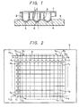
- a plate stand 5 is formed of a transparent plastic material, and its upper surface has, as shown in Fig. 1, substantially conical recesses 6 for receiving wells 8 of the microplate 7 at precise positions.
- Positioning openings 9 are perforated at the positions corresponding to vertexes of a rectangule and light passes through the plate stand 5 vertically upwardly.
- a main light source (not shown) is provided above the plate stand 5.
- An auxiliary light source of less power than the main light source may be provided below the plate stand 5. The coordinates of the positioning openings 9 are used to determine the center position of each well.
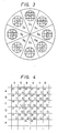
- each of a total of four linear lines is divided into 11 equal segments to obtain 12 points k1 ,.., k12, h1 ,.., h12 , m1 ,..m8 and n1 ,.., n8 are obtained, respectively.
- 12 lines y1 ,.., y12 connecting horizontally these points ki and hi and 8 linear lines x1 ,.., x8 connecting the points mi and ni are obtained.
- the cross points of the linear lines yi and xi are obtained, which are used as the centers of the wells.
- an image of each well is divided radially into 8 sectors S1, S2,.., S8 , and the differential values of the pixels in the sectors S1 to S8 are determined, respectively.
- the differential value of each pixel is a total of difference in luminance between the pixel and adjacent three respective pixels disposed radially outwardly of the pixel in question.
- pixels disposed adjacent to the left side, oblique upper left side and oblique lower left side of a pixel are to be compared in luminance with the latter and a total of differences are to be determined as the differential value of the pixel in question.
- Fig. 4 shows the differential values of the pixels in the sector S2 .
- the differential value of each pixel is determined.
- the values of the pixels aligned on one line are compared with each other to detect two pixels having largest two values in the same line as defining the edge of the agglutination. That is, when differential values are given as shown in Fig. 5, two pixels in, for example, lines which have largest value 38 are determined as defining the edge and, in line f, the pixels having values 34 and 33 are detected as defining the edge. Similarly, when the edges are selected for all the lines, the entire edge becomes as designated by a thick solid line as shown in Fig. 5 in which dotted chain lines indicate the actual edges of the agglutination portion.
- the number of the pixels inside the edge are counted, and the area of the agglutination is compared with a reference value.
- the contour of the agglutination is defined clearly by calculating the variation coefficient of the differential value and the contrast of the image is obtained by averaging the differential values.
- the distribution of pixels having luminance level other than zero is evaluated by means of a microcomputer.
- a standard deviation of the distribution is obtained and is divided by a mean luminance level to obtain a variation coefficient CV. Since the CV does not contain factors due to variation of contrast, the problem caused thereby can be completely removed.
- the CV values obtained in this manner are plotted in the area (number of the pixels) to obtain a distribution for special item, the judged results are superposed on the CV distribution to determine the boundary of the judgement, which is stored in a computer memory.
- agglutination images are judged by skilled visual judge personnel and results are also plotted.
- a linear line is set empirically to divide it to a region which is decided by the skilled personnel as positive and the other region which is decided as negative.
- the linear line is used as a reference line which is memorized.
- Figs. 6 and 7 show examples of the system for performing the above mentioned operation with reference to Figs. 1 to 5, respectively.
- an agglutination image on a microplate 7 is stored as a video image in a TV camera 12 in an image memory 13, and the stored image is differentiated and, then, an area of the image is obtained by an image processor 15.
- Standard deviation S of the pixel having intensity level not higher than zero is obtained by a standard deviation calculator 16 from the obtained profile and area of the image, and its CV is further obtained by a CV calculator 17.
- the CV is supplied to a plotter 18 together with the area obtained by the image processor 15, and is plotted on a graph having, for example, an ordinate as CV and abscissa as the area.
- Fig. 6 which shows a flow of a reaction container, i.e., a microplate having a plurality of wells in an automatic immunological agglutination judgement apparatus for performing the present method
- the reaction container is supplied from a container supply device 100 which is conveyed by an intermittent transportation device which is to be described later to a first position P1 in which a sample and a suitable reagent are poured by a sample/reagent pouring device 200 and, after a sample and reagent are supplied to each of the wells of the microplate, the microplate is conveyed to a second position P2 in which it is vibrated by an agitation device 300 to agitate the contents of the wells to thereby mix them in each well.
- a container supply device 100 which is conveyed by an intermittent transportation device which is to be described later to a first position P1 in which a sample and a suitable reagent are poured by a sample/reagent pouring device 200 and, after a sample and reagent are supplied to each
- the microplate is transported by the same transportation device over a substantial distance long enough to give a sufficient reaction time T to a third position P3 in which a resultant agglutination is detected by a detection device 400. Then, the microplate is transported to a fourth position P4 in which it is recovered by a container recovery device 500. An output of the detection device 400 is supplied to a judging device 600.
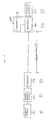
- FIG. 7 An example of a construction of a combined detection device/judging device A shown by a dotted line in Fig. 6 is shown in block in Fig. 7, although either of the constructions shown in Figs. 6 and 9 of the aforesaid EP-A-257660 may be used if necessary.
- Fig. 7 An example of a construction of a combined detection device/judging device A shown by a dotted line in Fig. 6 is shown in block in Fig. 7, although either of the constructions shown in Figs. 6 and 9 of the aforesaid EP-A-257660 may be used if necessary.
- an agglutination image of wells of a microplate 7 is picked up by a TV camera 12 of the detection device 400 which further includes an image memory 13 and is stored as a video image in the image memory 13 which is supplied to the judging device 600 comprising a image processor 14, a standard deviation calculator 15, a variation coefficient calculation device 16, a plotter 17, a memory 21 storing a boundary line obtained by skilled personnel and a comparator 22 for compring an output of the plotter 17 with the content of the memory.
- the judging device 600 may further include a contrast calculator 23 disposed between the variation coefficient calculator 16 and the plotter 17.
- FIG. 8 which is a perspective schematical illustration of the present apparatus
- Fig. 9 which is a top view of the apparatus
- Fig. 10 which is a side view thereof
- a transportation device 700 in the form of rotary disc is provided on a support frame 50 below which the judging device 600 is arranged.
- a plurality of microplates 7 can be received equiangularly.
- the microplates 7 are supplied from the container supply device 100 onto the transportation device 700 one by one while the latter is rotated by a suitable driving means 706 through a suitable transmission gear mechanism including a gear 704 mounted on a rotary shaft 702 of the transportation device 700.
- the container supply device 100 will be described in detail with reference to another embodiment of the apparatus.
- the microplate 7 fed from the container supply 100 onto the transportation device 700 is firstly carried to a sample/reagent supply position P1 thereby at which the sample and the reagent are poured to respective wells of the microplate 7 by means of a pouring nozzle member supported three dimensionally movably by a vertically movable support 206 which is movable in a horizntal plane. That is, the support 206 is supported by a lateral guide member 204 which, in turn, is supported by a pair of guide members 202 extending from a pouring device 200.
- a suction tube 208 is connected to the nozzle member to suck a predetermined volume of the sample from a sample holder 212 and to discharge it to the wells of the microplate 7 in the position P1.
- the nozzle member is changed sample by sample. New nozzles are picked up from a chip holder 214.
- the position of the nozzle is detected by a suitable detector connected through a lead wire 210 to a control portion of the pouring device 200 to control it suitably.
- the microplate is carried with intermittent rotation of the transportation device 700 to a position P2 at which the microplate 7 is vibrated to mix the sample and the reagent in the respective wells thereof.
- the positions P1 and P2 are overlapped, the position P2 can be set at a next position to the position P1.
- the vibration of the microplate 7 is achieved by an agitation device 300 such as shown in Fig. 11.
- a rod 310 has a spherical portion 312 in a center portion thereof, which is supported by a universal bearing 316 having a corresponding shape.
- a motor 318 is fixedly mounted on a lower end 310b of the rod 310 and an eccentric weight 322 is mounted on an output shaft 320 of the motor 318.
- a plate member 324 is fixed to an upper end 310a of the rod 310 on which the microplate 7 is suitably mounted fixedly.
- the motor 318 is connected through flexible lead wires 328 to a control/power source which are not shown. With rotation of the motor 318, the eccentric weight 322 is rotated by which a revolution momentum is produced on the output shaft 320 of the motor 318. Therefore, the rod 310 revolutes around the universal bearing as a fulcrum, so that the upper end 310a as well as the plate member 324 fixed thereon revolute similarly causing revolution of liquid in each of the wells of the microplate 7.
- the radius and speed of the revolution of the rod 310 are determined by rotation speed of the motor 318, eccentricity of the eccentric weight 322, length of the rod 310 and position of the universal bearing.
- the eccentricity, the rod length and the position of the universal bearing are fixed, the higher the motor speed provides the larger the radius and the higher the revolution speed.
- Fig. 12 shows another embodiment of the agitation device 300, by which the problem of overflow is solved.
- the plate member 324 is not fixed to the upper end 310a of the rod 310 but supported horizontally by a suitable support member 332.
- the plate member 324 is formed on a lower surface thereof a recess member 330 which receives the upper end 310a of the rod 310. With revolution of the rod 310, the plate member 324 slides horizontally on the support member 332 which may be formed integrally with the support member 314.
- the microplate 7 is transported to a position P3 in which the microplate 7 is illuminated by a light source 402 to pick up agglutination images of the respective wells thereof by means of a TV camera 400 output of which is suppied to a image processing device 600 in which the processing mentioned previously is performed.
- Fig. 13 is a plan view of another embodiment of the present apparatus in which the constitutional components are moved onto a middle deck 50 so that only the pouring operation is performed on a top deck 60.
- the embodiment will be described in detail with reference to Fig. 14 which is a front view thereof, Fig. 15 which is a side view thereof, Fig. 16 which shows a transportation device 700 in detail, Figs. 17a and 17b which show a container supply device 100, Figs. 18a and 18b which show a container recovery device 400, Fig. 19 which shows a device 800 for moving the microplate 7 to a pouring position and Fig. 20 which shows a agitation device 300.
- the top deck 60 is formed with an opening 62 through which a microplate 7 lifted up from the transportation device 700 by the elevation device 800 in the pouring position is exposed for pouring operation.
- the elevation device 800 is composed of a vertical lead screw 804 rotatably supported between the top and the middle decks 60 and 50 and a support member 110 in the form of cross plate having an arm an end portion 802 of which meshes with the lead screw 804 as best shown in Figs. 16 and 19.
- the container supply device 100 and the container recovery device 400 are supported by a support structure 54 fixed on the middle deck 50 as shown in Fig. 16.
- the agitation device 300 is suitably supported above the transportation device 700 by a structural frame and a TV camera 400 may be supportd by the top deck 60 as shown.
- the transportation device 700 in the form of rotary disc is rotatably supported by a shaft 702 supported by a bearing 52 supported by the middle deck 50.
- a gear 704 is fixedly mounted on a lower end of the shaft 702 which meshes with a gear 708 mounted on an output shaft of a motor 706 fixed on a lower surface of the middle deck 50 through a suitable transmission mechanism so that the disc 700 is rotated stepwise.
- the motor 706 may be a step motor.
- the disc 700 is formed with a plurality of generally rectangular openings 710 peripherally. Sides of each opening 710 are recessed respectively to allow a cross shaped elevation member 110 to pass through and an outer one of the sides is notched as shown by a numeral 712 to allow the arm of the elevation device 800 to pass through.
- the container supply device 100 comprises a generally rectangular cylinder shaped cover frame 102 having one side opened as shown in Fig. 17a.
- a plurality of microplates 7 are stacked therein and the lowest microplate 7 is supported by a pair of oppositely disposed flaps 104 as shown in Fig. 17b.
- the flaps 104 covers full width of the frame and are hinged at bottom edges of the frame 102 and biased by springs 106 such that they are kept horizontally to catch a bottom of the lowest microplate 7 and, when pushed up by the elevation member 110, turned-up to allow only the lowest microplate 7 to drop out from the frame 102.
- the elevation member 110 is supported by a od 112 coupled to a piston of a cylinder member 114 fixed to the middle deck 50.
- any other elevation mechanism may be used instead of the piston-cylinder mechanism.
- Fig. 18a shows the container recovery device 500 and Fig. 18b is a partial cross section of a bottom portion of the device 500, taken along a line B-B in Fig. 18a.
- the container recovery device 500 comprises, as in the case of the container supply device 100, a generally rectangular cylinder shaped frame 502 and two pairs of opposite flaps 504.
- Spring-biased hinge mechanism of the flaps 504 is substantially the same as that of the container supply device 100 except that corresponding flaps 504 of the respective pairs are separated from each other to allow the elevation member 110 to pass through. It should be noted that such elevation members 110 are provided in the positions P1, P2, P3 and P5, respectively.
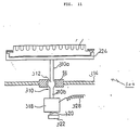
- Fig. 20 shows, in partially cross section, the agitation device 300.
- the agitation device 300 in Fig. 20 is fundamentally the same as that shown in Fig. 12, although inverted.
- the device 300 in Fig. 20 comprises a first support structure including an upper deck 318, a lower deck 320 and pillars 324 connecting the decks 318 and 320, a vibration mechanism including a motor 318 having an output shaft mounted an eccentric member 322 thereon, a rod 310 having an upper and a lower rod halves 310a and 310b and a center sphere 312 supported by a bearing 316 supported by the lower deck 320 and a second support structure for supporting a mcroplate catch mechanism including a pair of nails 352 and a control device 350 therefor attached to a lower end of the lower half 310a of the rod 310.
- the upper deck 318 is suitably fixed to the frame structure of the apparatus and each of the pillars is composed of a pair of rod portions 324.
- An upper end of the upper rod portion 324 is fixed to a lower surface of the upper deck 318 and a lower end thereof is connected through a shock absorber 326 to an upper end of the lower rod portion 324 whose lower end is connected through a similar shock absorber 326 to the lower deck 320. Therefore, a transmission of vibration to the apparatus structure is prevented.
- a solenoid 330 is fixed by a support 334.
- a plunger 332 of the solenoid 330 can penetrate the upper deck 318 into a recess 332a formed in a portion of the eccentric member 322 corresponding to the output shaft upon energization of the solenoid 330 when the agitation device stops to operate, so that undesirable swing motion of the microplate caught by the hook nails 352 is prevented.
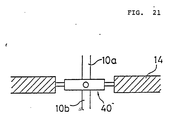
- Fig. 21 shows another embodiment of the universal bearing the agitation device.
- the universal bearing takes in the form of gimbal whose structure and operation are well known.
- the cylinder 114 associated therewith is actuated to lift up the associated elevation mmber 110 through the opening 710 of the disc 700 into the container supply device 100.
- the elevation member 110 pushes up the lowest microplate 7 while folding the flaps 104 thereof (Figs. 17a and 17b) and carries down and leaves it on the opening 710 of the disc 700 while retreaving.
- the microplate 7 on the disc 700 is then transported to the position P2 by a rotation thereof by a predetermined unit angle. At this time, the same operation is performed for a new opening 710 of the disc 700 which comes into the position P1.
- the motor 808 is actuated to rotate the lead screw 804 (Figs. 14 and 19) so that the portion of the arm 802 meshed therewith and hence the elevation member 110 is moved upwardly through the opening 710 of the disc 700 while picking the microplate 7 thereon up to ultimately position the microplate 7 in the opening 62 of the upper deck 60 of the apparatus.
- the pouring device 200 is actuated to pour predetermined liquid to the respective wells of the microplate.
- the motor 808 is reversed to rotate the lead screw 804 in reverse direction to thereby lower the elevation member 110 through the opening 710 of the disc 700, so that the microplate 7 is put on the disc 700 again.
- the disc is rotated by one step to the position P3.
- the elevation member 110 associated with that position is moved up to lift the microplate having liquid filled wells up to the hook nails 352 of the agitation device 300 arranged above the position P3 with the plunger 332 being received in the recess 322a of the eccentric member 322 and, at a top position of the elevation member 110, the nail control device 350 is actuated to hold the microplate by the nails 352.
- the solenoid 330 is deenergized to make the eccentric member 322 free and then the motor 318 is actuated to agitate liquid in the respective wells.
- the elevation member 110 is lowered through the opening 710 of the disc 700 leaving the microplate thereon. Thereafter, the disc 700 is rotated by several steps to the position P4. A time period required for transportation of the microplate from the position P3 to the position P4 should be long enough to obtain a desired degree of immunological reaction.
- the microplate 7 is illuminated through the opening 710 by the light source 402 and light passed through the microplate and containing agglutination information is picked up by the TV camera 400 the output of which is processed by the processor 600 as mentioned previously.
- the disc 700 is rotated by one step to transport the microplate to the position P5.
- the elevation member 110 associated therewith is lifted up through the opening 710 to push the microplate thereon into the bottom of the containter recovery device 500 arranged thereabove while folding the flaps 504 which are returned to the original states after the microplate passes therethrough.
- the elevation member 110 is lowered while leaving the microplate in the recovery device, and one cycle of operation completes. The same operation is performed for the microplates successively.
- a control device for controlling, in synchronism with the intermittent operation of the disc 700, the operations of the elevation member 110 associated with the container supply device 100, the pouring device 200 and the associated elevation device 800, the agitation device 300 and the associated elevation member 110, the TV camera and the associated light source 402 and the elevation member 110 associated with the container recovery device 500 may be easily constructed by those skilled in the art and, therefore, details thereof are omitted in this description.
- Figs. 22 to 24 are graphs useful to determine the time, i.e., the rotational speed of the rotary disc 700.
- Fig. 22 is a graph showing a relation of area obtained from a contour of agglutination determined by the image processor 600 to time
- Fig. 23 is a graph showing a relation of the contour of the agglutinated image to time
- Fig. 24 is a grapg sowing a relation of contrast of the agglutinated image to time, for anti-adult T cell leukemia antibody as a test item.
- the time necessary to achieve the desired reaction can be clearly defined around 30 minutes in the case of Fig. 22, around 50 minutes in the case of Fig. 23 and around 40 minutes in the case of Fig. 24. In any of these three cases, the time is much shorter than in the conventional case which may be around 2 to 3 hours.
- the present apparatus should be designed such that the container 7 on the rotary disc 700 moves from the position PS3 to PS4 for about 50 minutes or less.
Abstract
Description
- The present invention relates to an automatic analysis of immunological agglutination for use in clinical diagnosis and an apparatus for performing the same.
- The analysis utilizing immunological agglutinating reaction has been used popularly in clinical test due to its advantages in selectivity and high sensitivity. A classical example thereof is the identification of blood type based on agglutination of red corpuscles and a recent example is the measurement of antigen and/or antibody related to microorganism or cancer based on a utilization of new carriers.
- Examples of the apparatus which can automate such analysis or measurement are disclosed in Japanese Patent Application Laid-open Nos. 146044/1980, 111447/1982, 11858/1983, 22956/1983 and 105065/1983. In these prior arts, a series of operations based on the immunological agglutination reaction are automated to determine whether or not there is immunological reaction by optically analysing an agglutinated image. In each of these prior arts, however, a reference value of agglutination is obtained by measuring ratio of light amount passed through or reflected from a center portion of a conical container to that related to a peripheral portion thereof. Therefore, it is difficult to apply them to judgement of various agglutination images with high accuracy.
- That is, although the conventional judgement which uses permeable light usually, a solution for agglutination reaction contains, in addition to substance to be detected, various proteins which may be precipitated separately from a result of the aimed agglutination reaction causes a whole of the solution to be white by which the accuracy of measurement is degraded. Such phenomenon is usually caused by a complicated combination of an aimed substance and a test solution and, particularly, it becomes severe when a long time lapses after it is prepared by mixing the substance with the test solution or the solution contains proteins and/or salts at high concentration. Further, since, in the conventional system, an amount of light passed through the solution is considerably reduced by scattering thereof by those substances precipitated, the light amount obtained does usually not always correspond to an agglutination reaction. Therefore, when the judgement is to be performed by converting concentration into luminance, it is impossible to judge an agglutination exactly.
- Further, in the conventional optical detecting device for use in the judgement of agglutination, a reaction vessel or container is measured one by one. Therefore, it takes considerable time and requires a transportation device for moving microplates.
- In the clinical test field, there has been no real automatic apparatus for agglutinative immuno-analysis although there has been semiautomatic apparatus in which an operation is partially automated while important steps such as test sample pouring, transportation of the test samples from a retreatment device to a detection device and a judging steps are performed manually.
- An object of the present invention is to provide a fully automatic immunological agglutination analyzing method and an apparatus therefor which is capable of providing a highly precise, high speed analysis of immunological agglutination.
- The apparatus according to the present invention comprises a pretreatment device, a detection device and an evaluation device.
- The pretreatment device includes a plurality of reaction containers each taking in the form of a microplate having a plurality of wells, which are stacked in a container supply device. One of the microplates which is the lowest in the container supply device is derived and transported therefrom. The test sample pouring device may be one capable of drawing up a certain amount of test sample and pouring it to each of the wells of the microplate derived from the container supply device by an amout of 5 to 200µℓ. It is preferable that the pouring device is washable or exchangeable after the pouring operation of one test sample to avoid a contamination of another test sample by the one sample. A pouring portion of the pouring device is preferably movable three-dimensionally. A reagent supply device for supplying reagent to the wells of the microplate to which the test sample has been supplied includes a plurality of reagent pouring devices, a dilution device, a washing device for washing the dilution device, a washing liquid tank and a transportation device. The reagent pouring device includes a plurality of storage tanks each capable of storing a different reagent of around 200 mℓ and a plurality of pouring nozzles for supplying the reagents simultaneously to the wells. One of the reagent pouring devices supplies a diluting liquid to one of the wells by an amount of 5 to 200 µℓ and dilutes the test sample in the well by drawing up and discharging the liquid in the well repeatedly. Another of the reagent pouring devices pours an immunological agglutination reagent to each well by an amount of 5 to 200 µℓ . The microplate having the wells each filled with the test sample and the immunological agglutination reagent is transported to an agitation device. The agitation device may be of vibration type or rotation type. However, in order to eliminate undesired vibration of other portions of the apparatus, the vibration type agitator is preferable.
- After the agitation, the microplate is transported to the detection device. The detection device comprises an image pick-up device, a transportation device and a container collecting device. The image pick-up device includes an image input portion, an image memory, an image output portion, a camera and a suitable light source. The camera is, in this invention, a TV camera such as CCD or solid state image tube. However, the camera may be any visual sensor although TV camera is preferable in processing image data. Light from the light source passes through agglutination images of all of the wells of the microplate and it containing the agglutination image information is inputted to the TV camera by which the agglutination in the wells of the microplate is picked-up. That is, agglutinated images in the wells of the microplate is illuminated by light from the light source and lights passed through the respective wells are picked-up by the TV camera as optical informations. The light source used in this invention is enough to illuminate the all of the wells of the microplate uniformly. The optical information is supplied to the image input portion and stored in the image memory portion which is derived by the image output portion according to demand.
- In the present invention, the agglutination images can be picked up successively after a commencement of agglutination reaction or once after the agglutination reaction completes. In order to process the microplates which are transported successively to thereby perform either of the above mentioned image pick-up operations, it is preferable that the microplates are put in a detection position sequentially by the container transportation device which may be of a turn-table type whose rotation may be intermittent interval of which is controllable. When the final image is to be picked up, the container may be transported to the detection position after 90 to 120 minutes from a completion of the agitation.
- After the agglutination image information of one microplate, it is transported by the same container transportation device to the container collecting device.
- The judgement of agglutination is performed according to the technique entitled "Method and Apparatus for Judging Agglutination Pattern"disclosed in EP-A-257660 of Applicant.
- This will be described in brief with reference to Figs. 1 to 5. In these figures, a
plate stand 5 is formed of a transparent plastic material, and its upper surface has, as shown in Fig. 1, substantiallyconical recesses 6 for receivingwells 8 of themicroplate 7 at precise positions. Positioningopenings 9 are perforated at the positions corresponding to vertexes of a rectangule and light passes through the plate stand 5 vertically upwardly. A main light source (not shown) is provided above theplate stand 5. An auxiliary light source of less power than the main light source may be provided below theplate stand 5. The coordinates of thepositioning openings 9 are used to determine the center position of each well. In Fig. 2, it is assumed that the positions of the positioning openings are at coordinates of 9₁ (x₁,y₁), 9₂(x₂ ,y₂ )..9₄(x₄ ,y₄ ). Then a line connecting theopenings openings - Then, each of a total of four linear lines is divided into 11 equal segments to obtain 12 points k₁ ,.., k₁₂, h₁ ,.., h₁₂ , m₁ ,..m₈ and n₁ ,.., n₈ are obtained, respectively. Then, 12 lines y₁ ,.., y₁₂ connecting horizontally these points ki and hi and 8 linear lines x₁ ,.., x₈ connecting the points mi and ni are obtained. Then, the cross points of the linear lines yi and xi are obtained, which are used as the centers of the wells.
- Then, as shown in Fig. 3, an image of each well is divided radially into 8 sectors S₁, S₂,.., S₈ , and the differential values of the pixels in the sectors S₁ to S₈ are determined, respectively. The differential value of each pixel is a total of difference in luminance between the pixel and adjacent three respective pixels disposed radially outwardly of the pixel in question. In the sector S₁ , pixels disposed adjacent to the left side, oblique upper left side and oblique lower left side of a pixel are to be compared in luminance with the latter and a total of differences are to be determined as the differential value of the pixel in question. In the sector S₂ , pixels disposed adjacent to the upper side, left side and oblique upper left side of a pixel are comparaed in luminance with the latter and a total of differences are to be determined as a differential value thereof, and so on. Fig. 4 shows the differential values of the pixels in the sector S₂ . When the differential value of the pixel D-III having an intensity of "32" is considered, as an example, a differential value of this pixel is 37 because intensities of pixels D-II, C-II and C-III outwardly surrounding the pixel D-III are respectively "44", "47" and "42", i.e., 12(=44-32) + 15(=47-32) + 10(=42-32) = 37. Thus, the differential value of each pixel is determined.
- When the differential values of the respective pixels are determined, the values of the pixels aligned on one line are compared with each other to detect two pixels having largest two values in the same line as defining the edge of the agglutination. That is, when differential values are given as shown in Fig. 5, two pixels in, for example, lines which have
largest value 38 are determined as defining the edge and, in line f, thepixels having values - When final agglutination images belong to a certain kind, the values obtained as above mentioned are used as they are and, when there are series of images belonging to different kinds, a variation rate thereof is obtained.
- The distribution of pixels having luminance level other than zero is evaluated by means of a microcomputer. A standard deviation of the distribution is obtained and is divided by a mean luminance level to obtain a variation coefficient CV. Since the CV does not contain factors due to variation of contrast, the problem caused thereby can be completely removed. The CV values obtained in this manner are plotted in the area (number of the pixels) to obtain a distribution for special item, the judged results are superposed on the CV distribution to determine the boundary of the judgement, which is stored in a computer memory.
- Simultaneously, the same agglutination images are judged by skilled visual judge personnel and results are also plotted. On the latter plot, a linear line is set empirically to divide it to a region which is decided by the skilled personnel as positive and the other region which is decided as negative. The linear line is used as a reference line which is memorized.
- The judgement of the test sample is performed with reference to this reference line.
- The above mentioned judging system is well automated as disclosed in EP-A-257660.
- Figs. 6 and 7 show examples of the system for performing the above mentioned operation with reference to Figs. 1 to 5, respectively. In Fig. 6, an agglutination image on a
microplate 7 is stored as a video image in aTV camera 12 in animage memory 13, and the stored image is differentiated and, then, an area of the image is obtained by animage processor 15. - Standard deviation S of the pixel having intensity level not higher than zero is obtained by a
standard deviation calculator 16 from the obtained profile and area of the image, and its CV is further obtained by aCV calculator 17. The CV is supplied to a plotter 18 together with the area obtained by theimage processor 15, and is plotted on a graph having, for example, an ordinate as CV and abscissa as the area. In the drawing:
- Figs. 1 to 5 are explanatory illustrations for explaining a principle of contour derivation of agglutination image which can be used in the present invention effectively;
- Fig. 6 shows a flow of a reaction container in an apparatus for performing the present invention;
- Fig. 7 is a block diagram of a detection/judgement device suitable to use in the present apparatus;
- Fig. 8 is a perspective view of an embodiment of an automatic agglutination judging apparatus according to the present invention;
- Fig. 9 is a plan view of the apparatus shown in Fig. 8;
- Fig. 10 is a side view of the an automatic agglutination judging apparatus shown in Fig. 8;
- Fig. 11 shows, schematically, an agitation device suitable to use in the embodiment shown in Fig. 8;
- Fig. 12 shows another embodiment of the agitation device;
- Fig. 13 is a front view of another embodiment of the present apparatus, with a front wall portion thereof being removed;
- Fig. 14 is a plan view of the embodiment shown in Fig. 13;
- Fig. 15 is a side view of the apparatus shown in Fig. 13;
- Fig. 16 is a plane view of a reaction container transportation device of the embodiment shown in Fig. 13;
- Fig. 17a is a plan view of a container supply device of the apparatus shown in Fig. 13;
- Fig. 17b is a partially cross sectioned side view of a bottom portion of the container supply device;
- Fig. 18a is a plan view of a container recovery device of the apparatus in Fig. 13;
- Fig. 18b is a partially cross sectioned side view of the container recovery device;
- Fig. 19 shows, schematically, a vertical transportation device for transporting a container to a position in which a pouring operation thereto is performed;
- Fig. 20 is a front view of another embodiment of the agitation device;
- Fig. 21 shows a portion of another embodiment of the agitation device; and
- Figs. 22 to 24 are graphs showing references of judgement for ATLA.
- In Fig. 6 which shows a flow of a reaction container, i.e., a microplate having a plurality of wells in an automatic immunological agglutination judgement apparatus for performing the present method, the reaction container is supplied from a
container supply device 100 which is conveyed by an intermittent transportation device which is to be described later to a first position P1 in which a sample and a suitable reagent are poured by a sample/reagent pouring device 200 and, after a sample and reagent are supplied to each of the wells of the microplate, the microplate is conveyed to a second position P2 in which it is vibrated by anagitation device 300 to agitate the contents of the wells to thereby mix them in each well. After the agitation is completed, the microplate is transported by the same transportation device over a substantial distance long enough to give a sufficient reaction time T to a third position P3 in which a resultant agglutination is detected by adetection device 400. Then, the microplate is transported to a fourth position P4 in which it is recovered by acontainer recovery device 500. An output of thedetection device 400 is supplied to a judgingdevice 600. - An example of a construction of a combined detection device/judging device A shown by a dotted line in Fig. 6 is shown in block in Fig. 7, although either of the constructions shown in Figs. 6 and 9 of the aforesaid EP-A-257660 may be used if necessary. In Fig. 7, an agglutination image of wells of a
microplate 7 is picked up by aTV camera 12 of thedetection device 400 which further includes animage memory 13 and is stored as a video image in theimage memory 13 which is supplied to the judgingdevice 600 comprising aimage processor 14, astandard deviation calculator 15, a variationcoefficient calculation device 16, aplotter 17, amemory 21 storing a boundary line obtained by skilled personnel and acomparator 22 for compring an output of theplotter 17 with the content of the memory. If necessary, the judgingdevice 600 may further include acontrast calculator 23 disposed between thevariation coefficient calculator 16 and theplotter 17. - An embodiment of the present apparatus is shown in Figs. 8 to 11, in detail. In Fig. 8 which is a perspective schematical illustration of the present apparatus, Fig. 9 which is a top view of the apparatus and Fig. 10 which is a side view thereof, a
transportation device 700 in the form of rotary disc is provided on asupport frame 50 below which the judgingdevice 600 is arranged. On thetransportation device 700, a plurality of microplates 7 can be received equiangularly. The microplates 7 are supplied from thecontainer supply device 100 onto thetransportation device 700 one by one while the latter is rotated by a suitable driving means 706 through a suitable transmission gear mechanism including agear 704 mounted on arotary shaft 702 of thetransportation device 700. Thecontainer supply device 100 will be described in detail with reference to another embodiment of the apparatus.Themicroplate 7 fed from thecontainer supply 100 onto thetransportation device 700 is firstly carried to a sample/reagent supply position P1 thereby at which the sample and the reagent are poured to respective wells of themicroplate 7 by means of a pouring nozzle member supported three dimensionally movably by a verticallymovable support 206 which is movable in a horizntal plane. That is, thesupport 206 is supported by alateral guide member 204 which, in turn, is supported by a pair ofguide members 202 extending from a pouringdevice 200. Asuction tube 208 is connected to the nozzle member to suck a predetermined volume of the sample from asample holder 212 and to discharge it to the wells of themicroplate 7 in the position P1. The nozzle member is changed sample by sample. New nozzles are picked up from a chip holder 214. The position of the nozzle is detected by a suitable detector connected through alead wire 210 to a control portion of the pouringdevice 200 to control it suitably. - After the pouring operation is completed, the microplate is carried with intermittent rotation of the
transportation device 700 to a position P2 at which themicroplate 7 is vibrated to mix the sample and the reagent in the respective wells thereof. Although, in Fig. 9, the positions P1 and P2 are overlapped, the position P2 can be set at a next position to the position P1. The vibration of themicroplate 7 is achieved by anagitation device 300 such as shown in Fig. 11. - In Fig. 11, a
rod 310 has aspherical portion 312 in a center portion thereof, which is supported by auniversal bearing 316 having a corresponding shape. Amotor 318 is fixedly mounted on a lower end 310b of therod 310 and aneccentric weight 322 is mounted on anoutput shaft 320 of themotor 318. - A
plate member 324 is fixed to anupper end 310a of therod 310 on which themicroplate 7 is suitably mounted fixedly. Themotor 318 is connected through flexiblelead wires 328 to a control/power source which are not shown. With rotation of themotor 318, theeccentric weight 322 is rotated by which a revolution momentum is produced on theoutput shaft 320 of themotor 318. Therefore, therod 310 revolutes around the universal bearing as a fulcrum, so that theupper end 310a as well as theplate member 324 fixed thereon revolute similarly causing revolution of liquid in each of the wells of themicroplate 7. - The radius and speed of the revolution of the
rod 310 are determined by rotation speed of themotor 318, eccentricity of theeccentric weight 322, length of therod 310 and position of the universal bearing. When the eccentricity, the rod length and the position of the universal bearing are fixed, the higher the motor speed provides the larger the radius and the higher the revolution speed. Theoritically, it is possible to make a vibration component given to the support structure of the apparatus zero by suitably balancing upper and lower movable portions of this agitation device with respect to the universal bearing. It should be noted in this embodiment of the agitation device that there is an overflow problem of liquid in the wells due to inclination of theplate member 324 when the revolution radius is too large. - Fig. 12 shows another embodiment of the
agitation device 300, by which the problem of overflow is solved. In Fig. 12, theplate member 324 is not fixed to theupper end 310a of therod 310 but supported horizontally by asuitable support member 332. Theplate member 324 is formed on a lower surface thereof arecess member 330 which receives theupper end 310a of therod 310. With revolution of therod 310, theplate member 324 slides horizontally on thesupport member 332 which may be formed integrally with thesupport member 314. - After the agitation is completed, the
microplate 7 is transported to a position P3 in which themicroplate 7 is illuminated by alight source 402 to pick up agglutination images of the respective wells thereof by means of aTV camera 400 output of which is suppied to aimage processing device 600 in which the processing mentioned previously is performed. - In order to give a time T (Fig. 6) long enough to achieve immunological reaction in the wells, a distance between the positions P2 and P3 is made large. Then, the
microplate 7 is transported to a position P4 in which it is recovered in acontainer recovery device 400 which will be descibed in detail later. - Fig. 13 is a plan view of another embodiment of the present apparatus in which the constitutional components are moved onto a
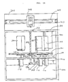
middle deck 50 so that only the pouring operation is performed on atop deck 60. The embodiment will be described in detail with reference to Fig. 14 which is a front view thereof, Fig. 15 which is a side view thereof, Fig. 16 which shows atransportation device 700 in detail, Figs. 17a and 17b which show acontainer supply device 100, Figs. 18a and 18b which show acontainer recovery device 400, Fig. 19 which shows adevice 800 for moving themicroplate 7 to a pouring position and Fig. 20 which shows aagitation device 300. - In Fig. 13, the
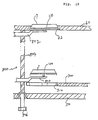
top deck 60 is formed with anopening 62 through which amicroplate 7 lifted up from thetransportation device 700 by theelevation device 800 in the pouring position is exposed for pouring operation. Theelevation device 800 is composed of avertical lead screw 804 rotatably supported between the top and themiddle decks support member 110 in the form of cross plate having an arm anend portion 802 of which meshes with thelead screw 804 as best shown in Figs. 16 and 19. Thecontainer supply device 100 and thecontainer recovery device 400 are supported by asupport structure 54 fixed on themiddle deck 50 as shown in Fig. 16. Theagitation device 300 is suitably supported above thetransportation device 700 by a structural frame and aTV camera 400 may be supportd by thetop deck 60 as shown. - The
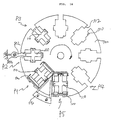
transportation device 700 in the form of rotary disc is rotatably supported by ashaft 702 supported by abearing 52 supported by themiddle deck 50. Agear 704 is fixedly mounted on a lower end of theshaft 702 which meshes with a gear 708 mounted on an output shaft of amotor 706 fixed on a lower surface of themiddle deck 50 through a suitable transmission mechanism so that thedisc 700 is rotated stepwise. Themotor 706 may be a step motor. Thedisc 700 is formed with a plurality of generallyrectangular openings 710 peripherally. Sides of eachopening 710 are recessed respectively to allow a cross shapedelevation member 110 to pass through and an outer one of the sides is notched as shown by a numeral 712 to allow the arm of theelevation device 800 to pass through. - The
container supply device 100 comprises a generally rectangular cylinder shapedcover frame 102 having one side opened as shown in Fig. 17a. A plurality of microplates 7 are stacked therein and thelowest microplate 7 is supported by a pair of oppositely disposedflaps 104 as shown in Fig. 17b. Theflaps 104 covers full width of the frame and are hinged at bottom edges of theframe 102 and biased by springs 106 such that they are kept horizontally to catch a bottom of thelowest microplate 7 and, when pushed up by theelevation member 110, turned-up to allow only thelowest microplate 7 to drop out from theframe 102. In this embodiment, theelevation member 110 is supported by aod 112 coupled to a piston of acylinder member 114 fixed to themiddle deck 50. However, any other elevation mechanism may be used instead of the piston-cylinder mechanism. - Fig. 18a shows the
container recovery device 500 and Fig. 18b is a partial cross section of a bottom portion of thedevice 500, taken along a line B-B in Fig. 18a. Thecontainer recovery device 500 comprises, as in the case of thecontainer supply device 100, a generally rectangular cylinder shapedframe 502 and two pairs ofopposite flaps 504. Spring-biased hinge mechanism of theflaps 504 is substantially the same as that of thecontainer supply device 100 except that correspondingflaps 504 of the respective pairs are separated from each other to allow theelevation member 110 to pass through. It should be noted thatsuch elevation members 110 are provided in the positions P1, P2, P3 and P5, respectively. - Fig. 20 shows, in partially cross section, the
agitation device 300. Theagitation device 300 in Fig. 20 is fundamentally the same as that shown in Fig. 12, although inverted. Thedevice 300 in Fig. 20 comprises a first support structure including anupper deck 318, alower deck 320 andpillars 324 connecting thedecks motor 318 having an output shaft mounted aneccentric member 322 thereon, arod 310 having an upper and alower rod halves 310a and 310b and acenter sphere 312 supported by abearing 316 supported by thelower deck 320 and a second support structure for supporting a mcroplate catch mechanism including a pair ofnails 352 and acontrol device 350 therefor attached to a lower end of thelower half 310a of therod 310. - The
upper deck 318 is suitably fixed to the frame structure of the apparatus and each of the pillars is composed of a pair ofrod portions 324. An upper end of theupper rod portion 324 is fixed to a lower surface of theupper deck 318 and a lower end thereof is connected through ashock absorber 326 to an upper end of thelower rod portion 324 whose lower end is connected through asimilar shock absorber 326 to thelower deck 320. Therefore, a transmission of vibration to the apparatus structure is prevented. - On the
upper deck 318, asolenoid 330 is fixed by asupport 334. Aplunger 332 of thesolenoid 330 can penetrate theupper deck 318 into a recess 332a formed in a portion of theeccentric member 322 corresponding to the output shaft upon energization of thesolenoid 330 when the agitation device stops to operate, so that undesirable swing motion of the microplate caught by the hook nails 352 is prevented. Fig. 21 shows another embodiment of the universal bearing the agitation device. The universal bearing takes in the form of gimbal whose structure and operation are well known. - An operation of the embodiment shown in Figs. 13 through 20 will be described with reference to Fig. 16.
- In the position P1, the
cylinder 114 associated therewith is actuated to lift up the associatedelevation mmber 110 through theopening 710 of thedisc 700 into thecontainer supply device 100. Theelevation member 110 pushes up thelowest microplate 7 while folding theflaps 104 thereof (Figs. 17a and 17b) and carries down and leaves it on theopening 710 of thedisc 700 while retreaving. - The
microplate 7 on thedisc 700 is then transported to the position P2 by a rotation thereof by a predetermined unit angle. At this time, the same operation is performed for anew opening 710 of thedisc 700 which comes into the position P1. In the position P2, themotor 808 is actuated to rotate the lead screw 804 (Figs. 14 and 19) so that the portion of thearm 802 meshed therewith and hence theelevation member 110 is moved upwardly through theopening 710 of thedisc 700 while picking themicroplate 7 thereon up to ultimately position themicroplate 7 in theopening 62 of theupper deck 60 of the apparatus. When themicroplate 7 is fixedly positioned in theopening 62, the pouringdevice 200 is actuated to pour predetermined liquid to the respective wells of the microplate. - After the pouring operation is completed, the
motor 808 is reversed to rotate thelead screw 804 in reverse direction to thereby lower theelevation member 110 through theopening 710 of thedisc 700, so that themicroplate 7 is put on thedisc 700 again. Then the disc is rotated by one step to the position P3. In the position P3, theelevation member 110 associated with that position is moved up to lift the microplate having liquid filled wells up to the hook nails 352 of theagitation device 300 arranged above the position P3 with theplunger 332 being received in therecess 322a of theeccentric member 322 and, at a top position of theelevation member 110, thenail control device 350 is actuated to hold the microplate by thenails 352. When themicroplate 7 is caught by thenails 352, thesolenoid 330 is deenergized to make theeccentric member 322 free and then themotor 318 is actuated to agitate liquid in the respective wells. - After the agitation is completed, the
elevation member 110 is lowered through theopening 710 of thedisc 700 leaving the microplate thereon. Thereafter, thedisc 700 is rotated by several steps to the position P4. A time period required for transportation of the microplate from the position P3 to the position P4 should be long enough to obtain a desired degree of immunological reaction. In the position P4, themicroplate 7 is illuminated through theopening 710 by thelight source 402 and light passed through the microplate and containing agglutination information is picked up by theTV camera 400 the output of which is processed by theprocessor 600 as mentioned previously. - Then, the
disc 700 is rotated by one step to transport the microplate to the position P5. In the position P5, theelevation member 110 associated therewith is lifted up through theopening 710 to push the microplate thereon into the bottom of thecontainter recovery device 500 arranged thereabove while folding theflaps 504 which are returned to the original states after the microplate passes therethrough. Then, theelevation member 110 is lowered while leaving the microplate in the recovery device, and one cycle of operation completes. The same operation is performed for the microplates successively. - A control device for controlling, in synchronism with the intermittent operation of the
disc 700, the operations of theelevation member 110 associated with thecontainer supply device 100, the pouringdevice 200 and the associatedelevation device 800, theagitation device 300 and the associatedelevation member 110, the TV camera and the associatedlight source 402 and theelevation member 110 associated with thecontainer recovery device 500 may be easily constructed by those skilled in the art and, therefore, details thereof are omitted in this description. - The time to be given for the travel of the
container 7 on therotary disc 700 from the position PS3 to the position PS4, which is enough to achieve the desired antigen-antibody reaction in the wells should be as short as possible in designing the present apparatus. Figs. 22 to 24 are graphs useful to determine the time, i.e., the rotational speed of therotary disc 700. - Fig. 22 is a graph showing a relation of area obtained from a contour of agglutination determined by the
image processor 600 to time, Fig. 23 is a graph showing a relation of the contour of the agglutinated image to time and Fig. 24 is a grapg sowing a relation of contrast of the agglutinated image to time, for anti-adult T cell leukemia antibody as a test item. As is clear from Figs. 22 to 24, the time necessary to achieve the desired reaction can be clearly defined around 30 minutes in the case of Fig. 22, around 50 minutes in the case of Fig. 23 and around 40 minutes in the case of Fig. 24. In any of these three cases, the time is much shorter than in the conventional case which may be around 2 to 3 hours. Thus, the present apparatus should be designed such that thecontainer 7 on therotary disc 700 moves from the position PS3 to PS4 for about 50 minutes or less.
Claims (11)
Applications Claiming Priority (4)
| Application Number | Priority Date | Filing Date | Title |
|---|---|---|---|
| JP190214/87 | 1987-07-31 | ||
| JP19021487A JPS6435374A (en) | 1987-07-31 | 1987-07-31 | Method and apparatus for fully automatic agglutination immune analysis |
| JP62212720A JP2762272B2 (en) | 1987-08-28 | 1987-08-28 | Stirring and mixing equipment |
| JP212720/87 | 1987-08-28 |
Publications (3)
| Publication Number | Publication Date |
|---|---|
| EP0301583A2 true EP0301583A2 (en) | 1989-02-01 |
| EP0301583A3 EP0301583A3 (en) | 1989-05-03 |
| EP0301583B1 EP0301583B1 (en) | 1994-04-27 |
Family
ID=26505939
Family Applications (1)
| Application Number | Title | Priority Date | Filing Date |
|---|---|---|---|
| EP88112355A Expired - Lifetime EP0301583B1 (en) | 1987-07-31 | 1988-07-29 | Automatic immunological analysing apparatus |
Country Status (2)
| Country | Link |
|---|---|
| EP (1) | EP0301583B1 (en) |
| DE (1) | DE3889261D1 (en) |
Cited By (17)
| Publication number | Priority date | Publication date | Assignee | Title |
|---|---|---|---|---|
| EP0625708A2 (en) * | 1993-05-17 | 1994-11-23 | Fujirebio Inc. | Method and apparatus for indirect agglutination immunoassay |
| EP0753749A1 (en) * | 1995-07-13 | 1997-01-15 | Ciba Corning Diagnostics Corp. | Loading mechanism for sets of disposable elements |
| WO2001057538A1 (en) * | 2000-02-01 | 2001-08-09 | Incyte Genomics, Inc. | Method and apparatus for shuttling microtitre plates |
| US6325114B1 (en) | 2000-02-01 | 2001-12-04 | Incyte Genomics, Inc. | Pipetting station apparatus |
| EP1186891A1 (en) * | 2000-09-05 | 2002-03-13 | Tecan Schweiz AG | Holder for microtiterplate |
| WO2002042740A1 (en) * | 2000-11-27 | 2002-05-30 | Novozymes A/S | Automated mechanical stress assay for screening cleaning ingredients |
| US7070920B2 (en) | 1998-07-14 | 2006-07-04 | Cozart Bioscience Limited | Screening arrangment for screening immunoassay tests and agglutination tests |
| US7422860B2 (en) | 2001-02-07 | 2008-09-09 | Massachusetts Institute Of Technology | Optoelectronic detection system |
| US7517660B2 (en) | 1997-12-09 | 2009-04-14 | Massachusetts Institute Of Technology | Optoelectronic sensor |
| WO2009063185A1 (en) * | 2007-11-14 | 2009-05-22 | Surescreen Diagnostics Limited | Test results reading method and apparatus |
| US7736589B2 (en) | 2000-11-27 | 2010-06-15 | Novozymes A/S | Automated mechanical stress assay for screening cleaning ingredients |
| US7947509B2 (en) | 2001-02-07 | 2011-05-24 | Massachusetts Institute Of Technology | Optoelectronic detection system |
| US8216797B2 (en) | 2001-02-07 | 2012-07-10 | Massachusetts Institute Of Technology | Pathogen detection biosensor |
| CN104596934A (en) * | 2014-12-30 | 2015-05-06 | 浙江海洋学院 | Spectrophotometer with mixer |
| WO2017100652A1 (en) * | 2015-12-09 | 2017-06-15 | Indevr, Inc. | Automated agglutination analyzer with thresholding |
| EP3450985A1 (en) * | 2017-08-31 | 2019-03-06 | Tecan Trading Ag | Microplate processing device |
| US10948420B2 (en) | 2015-12-09 | 2021-03-16 | Indevr, Inc. | Automated agglutination analyzer with contour comparison |
Families Citing this family (2)
| Publication number | Priority date | Publication date | Assignee | Title |
|---|---|---|---|---|
| DK2823031T3 (en) | 2012-03-06 | 2018-06-25 | Bekon Gmbh | BIOREACTOR FOR METHANIZING BIOMASS AND PROCEDURE FOR OPERATING SUCH A BIOREACTOR |
| EP3112874A1 (en) * | 2015-07-02 | 2017-01-04 | Roche Diagnostics GmbH | Storage module, method of operating a laboratory automation system and laboratory automation system |
Citations (7)
| Publication number | Priority date | Publication date | Assignee | Title |
|---|---|---|---|---|
| US3636777A (en) * | 1969-09-16 | 1972-01-25 | Vision Lab Inc | Laboratory beaker transporter and elevator |
| FR2357881A1 (en) * | 1976-07-09 | 1978-02-03 | Dev Automat Biolog | Testing liq. microsamples esp. blood with various reagents - with multiple reagent syringes operating simultaneously to load and discharge |
| FR2373065A1 (en) * | 1976-12-03 | 1978-06-30 | Nat Res Dev | EQUIPMENT, AND EQUIPMENT ELEMENTS, FOR AUTOMATION OF SEPARATE SAMPLE ANALYZES |
| FR2390720A1 (en) * | 1977-05-09 | 1978-12-08 | Sclavo Inst Sieroterapeut | AUTOMATIC ANALYSIS OF FLUID COMPONENTS |
| EP0051496A1 (en) * | 1980-11-04 | 1982-05-12 | Olympus Optical Co., Ltd. | Analyzing method and apparatus for immunological agglutinating reaction |
| GB2130367A (en) * | 1982-11-19 | 1984-05-31 | Seiko Instr & Electronics | Analytical sample vessel manipulator |
| GB2131168A (en) * | 1982-11-30 | 1984-06-13 | Japan Tectron Instr Corp | Automatic analysis apparatus |
-
1988
- 1988-07-29 EP EP88112355A patent/EP0301583B1/en not_active Expired - Lifetime
- 1988-07-29 DE DE3889261T patent/DE3889261D1/en not_active Expired - Lifetime
Patent Citations (7)
| Publication number | Priority date | Publication date | Assignee | Title |
|---|---|---|---|---|
| US3636777A (en) * | 1969-09-16 | 1972-01-25 | Vision Lab Inc | Laboratory beaker transporter and elevator |
| FR2357881A1 (en) * | 1976-07-09 | 1978-02-03 | Dev Automat Biolog | Testing liq. microsamples esp. blood with various reagents - with multiple reagent syringes operating simultaneously to load and discharge |
| FR2373065A1 (en) * | 1976-12-03 | 1978-06-30 | Nat Res Dev | EQUIPMENT, AND EQUIPMENT ELEMENTS, FOR AUTOMATION OF SEPARATE SAMPLE ANALYZES |
| FR2390720A1 (en) * | 1977-05-09 | 1978-12-08 | Sclavo Inst Sieroterapeut | AUTOMATIC ANALYSIS OF FLUID COMPONENTS |
| EP0051496A1 (en) * | 1980-11-04 | 1982-05-12 | Olympus Optical Co., Ltd. | Analyzing method and apparatus for immunological agglutinating reaction |
| GB2130367A (en) * | 1982-11-19 | 1984-05-31 | Seiko Instr & Electronics | Analytical sample vessel manipulator |
| GB2131168A (en) * | 1982-11-30 | 1984-06-13 | Japan Tectron Instr Corp | Automatic analysis apparatus |
Cited By (33)
| Publication number | Priority date | Publication date | Assignee | Title |
|---|---|---|---|---|
| EP0625708A3 (en) * | 1993-05-17 | 1995-10-11 | Fujirebio Kk | Method and apparatus for indirect agglutination immunoassay. |
| US6124139A (en) * | 1993-05-17 | 2000-09-26 | Fujirebio Inc. | Method and apparatus for indirect agglutination immunoassay |
| EP0625708A2 (en) * | 1993-05-17 | 1994-11-23 | Fujirebio Inc. | Method and apparatus for indirect agglutination immunoassay |
| EP0753749A1 (en) * | 1995-07-13 | 1997-01-15 | Ciba Corning Diagnostics Corp. | Loading mechanism for sets of disposable elements |
| US5674047A (en) * | 1995-07-13 | 1997-10-07 | Chiron Diagnostics Corporation | Loading mechanism for probe tip tray |
| US7517660B2 (en) | 1997-12-09 | 2009-04-14 | Massachusetts Institute Of Technology | Optoelectronic sensor |
| US8722347B2 (en) | 1997-12-09 | 2014-05-13 | Massachusetts Institute Of Technology | Optoelectronic sensor |
| US7803633B2 (en) | 1998-07-14 | 2010-09-28 | Cozart Bioscience Limited | Screening arrangement for screening immunoassay tests and agglutination tests |
| US7070920B2 (en) | 1998-07-14 | 2006-07-04 | Cozart Bioscience Limited | Screening arrangment for screening immunoassay tests and agglutination tests |
| WO2001057538A1 (en) * | 2000-02-01 | 2001-08-09 | Incyte Genomics, Inc. | Method and apparatus for shuttling microtitre plates |
| US6325114B1 (en) | 2000-02-01 | 2001-12-04 | Incyte Genomics, Inc. | Pipetting station apparatus |
| US6739448B1 (en) | 2000-02-01 | 2004-05-25 | Incyte Corporation | Method and apparatus for shuttling microtitre plates |
| WO2002021145A1 (en) * | 2000-09-05 | 2002-03-14 | Tecan Trading Ag | Support for a microtiter plate |
| EP1186891A1 (en) * | 2000-09-05 | 2002-03-13 | Tecan Schweiz AG | Holder for microtiterplate |
| US7736589B2 (en) | 2000-11-27 | 2010-06-15 | Novozymes A/S | Automated mechanical stress assay for screening cleaning ingredients |
| WO2002042740A1 (en) * | 2000-11-27 | 2002-05-30 | Novozymes A/S | Automated mechanical stress assay for screening cleaning ingredients |
| US9494579B2 (en) | 2001-02-07 | 2016-11-15 | Massachusetts Institute Of Technology | Optoelectronic detection system |
| US7947509B2 (en) | 2001-02-07 | 2011-05-24 | Massachusetts Institute Of Technology | Optoelectronic detection system |
| US8067184B2 (en) | 2001-02-07 | 2011-11-29 | Massachusetts Institute Of Technology | Optoelectronic detection system |
| US8216797B2 (en) | 2001-02-07 | 2012-07-10 | Massachusetts Institute Of Technology | Pathogen detection biosensor |
| US8835127B2 (en) | 2001-02-07 | 2014-09-16 | Massachusetts Institute Of Technology | Optoelectronic detection system |
| US9005989B2 (en) | 2001-02-07 | 2015-04-14 | Massachusetts Institute Of Technology | Optoelectronic detection system |
| US7422860B2 (en) | 2001-02-07 | 2008-09-09 | Massachusetts Institute Of Technology | Optoelectronic detection system |
| US9291549B2 (en) | 2001-02-07 | 2016-03-22 | Massachusetts Institute Of Technology | Pathogen detection biosensor |
| WO2009063185A1 (en) * | 2007-11-14 | 2009-05-22 | Surescreen Diagnostics Limited | Test results reading method and apparatus |
| CN104596934A (en) * | 2014-12-30 | 2015-05-06 | 浙江海洋学院 | Spectrophotometer with mixer |
| WO2017100652A1 (en) * | 2015-12-09 | 2017-06-15 | Indevr, Inc. | Automated agglutination analyzer with thresholding |
| US10948420B2 (en) | 2015-12-09 | 2021-03-16 | Indevr, Inc. | Automated agglutination analyzer with contour comparison |
| EP3450985A1 (en) * | 2017-08-31 | 2019-03-06 | Tecan Trading Ag | Microplate processing device |
| WO2019042599A1 (en) * | 2017-08-31 | 2019-03-07 | Tecan Trading Ag | Microplate processing device |
| CN110892271A (en) * | 2017-08-31 | 2020-03-17 | 泰肯贸易股份公司 | Microplate processing apparatus |
| US11519926B2 (en) | 2017-08-31 | 2022-12-06 | Tecan Trading Ag | Microplate processing device |
| CN110892271B (en) * | 2017-08-31 | 2023-12-15 | 帝肯贸易股份公司 | Microplate processing device |
Also Published As
| Publication number | Publication date |
|---|---|
| EP0301583A3 (en) | 1989-05-03 |
| DE3889261D1 (en) | 1994-06-01 |
| EP0301583B1 (en) | 1994-04-27 |
Similar Documents
| Publication | Publication Date | Title |
|---|---|---|
| EP0301583B1 (en) | Automatic immunological analysing apparatus | |
| US5817526A (en) | Method and apparatus for agglutination immunoassay | |
| US6162399A (en) | Universal apparatus for clinical analysis | |
| EP2908952B1 (en) | Condensation-reducing sample tube array system | |
| US9260763B2 (en) | Sample processing method using tube strips and tube strip holder | |
| EP0588931A1 (en) | Automated specimen analyzing apparatus and method | |
| JPS58105065A (en) | Analyzer based on emmunological agglutination | |
| US9135515B2 (en) | Automated pelletized sample vision inspection apparatus and methods | |
| KR101922718B1 (en) | Method for determining the result of an agglutination reaction and microplate for determining products of agglutination reactions | |
| US9873921B2 (en) | Ultrasonic biological sample analysis apparatus and methods | |
| US20140112829A1 (en) | Tube strip handling and heating apparatus | |
| US9435718B2 (en) | Automated pelletized sample decanting apparatus and methods | |
| US10704996B2 (en) | Machinery for an automated analysis of the slides in accordance with the indirect immunofluorescence assay—IFA | |
| JPH08304401A (en) | Inspection instrument for specimen | |
| US9310281B2 (en) | Automated pelletized sample blotting apparatus and methods | |
| JPH08304400A (en) | Inspection device for specimen | |
| JPS5822956A (en) | Analysis and apparatus based on immunological agglutinating reaction |
Legal Events
| Date | Code | Title | Description |
|---|---|---|---|
| PUAI | Public reference made under article 153(3) epc to a published international application that has entered the european phase |
Free format text: ORIGINAL CODE: 0009012 |
|
| AK | Designated contracting states |
Kind code of ref document: A2 Designated state(s): CH DE FR GB IT LI NL |
|
| PUAL | Search report despatched |
Free format text: ORIGINAL CODE: 0009013 |
|
| AK | Designated contracting states |
Kind code of ref document: A3 Designated state(s): CH DE FR GB IT LI NL |
|
| 17P | Request for examination filed |
Effective date: 19890413 |
|
| 17Q | First examination report despatched |
Effective date: 19910215 |
|
| GRAA | (expected) grant |
Free format text: ORIGINAL CODE: 0009210 |
|
| AK | Designated contracting states |
Kind code of ref document: B1 Designated state(s): CH DE FR GB IT LI NL |
|
| PG25 | Lapsed in a contracting state [announced via postgrant information from national office to epo] |
Ref country code: NL Effective date: 19940427 Ref country code: DE Effective date: 19940427 |
|
| REF | Corresponds to: |
Ref document number: 3889261 Country of ref document: DE Date of ref document: 19940601 |
|
| ET | Fr: translation filed | ||
| ITF | It: translation for a ep patent filed |
Owner name: SAIC BREVETTI S.R.L. |
|
| PG25 | Lapsed in a contracting state [announced via postgrant information from national office to epo] |
Ref country code: GB Effective date: 19940729 |
|
| PG25 | Lapsed in a contracting state [announced via postgrant information from national office to epo] |
Ref country code: LI Effective date: 19940731 Ref country code: CH Effective date: 19940731 |
|
| NLV1 | Nl: lapsed or annulled due to failure to fulfill the requirements of art. 29p and 29m of the patents act | ||
| PLBE | No opposition filed within time limit |
Free format text: ORIGINAL CODE: 0009261 |
|
| STAA | Information on the status of an ep patent application or granted ep patent |
Free format text: STATUS: NO OPPOSITION FILED WITHIN TIME LIMIT |
|
| GBPC | Gb: european patent ceased through non-payment of renewal fee |
Effective date: 19940729 |
|
| PG25 | Lapsed in a contracting state [announced via postgrant information from national office to epo] |
Ref country code: FR Effective date: 19950331 |
|
| REG | Reference to a national code |
Ref country code: CH Ref legal event code: PL |
|
| 26N | No opposition filed | ||
| REG | Reference to a national code |
Ref country code: FR Ref legal event code: ST |
|
| PG25 | Lapsed in a contracting state [announced via postgrant information from national office to epo] |
Ref country code: IT Free format text: LAPSE BECAUSE OF NON-PAYMENT OF DUE FEES;WARNING: LAPSES OF ITALIAN PATENTS WITH EFFECTIVE DATE BEFORE 2007 MAY HAVE OCCURRED AT ANY TIME BEFORE 2007. THE CORRECT EFFECTIVE DATE MAY BE DIFFERENT FROM THE ONE RECORDED. Effective date: 20050729 |