EP0307672A1 - Active spall suppression armor - Google Patents
Active spall suppression armor Download PDFInfo
- Publication number
- EP0307672A1 EP0307672A1 EP88113787A EP88113787A EP0307672A1 EP 0307672 A1 EP0307672 A1 EP 0307672A1 EP 88113787 A EP88113787 A EP 88113787A EP 88113787 A EP88113787 A EP 88113787A EP 0307672 A1 EP0307672 A1 EP 0307672A1
- Authority
- EP
- European Patent Office
- Prior art keywords
- spall
- backing material
- armor
- alumina
- stress
- Prior art date
- Legal status (The legal status is an assumption and is not a legal conclusion. Google has not performed a legal analysis and makes no representation as to the accuracy of the status listed.)
- Granted
Links
Images


Classifications
-
- F—MECHANICAL ENGINEERING; LIGHTING; HEATING; WEAPONS; BLASTING
- F41—WEAPONS
- F41H—ARMOUR; ARMOURED TURRETS; ARMOURED OR ARMED VEHICLES; MEANS OF ATTACK OR DEFENCE, e.g. CAMOUFLAGE, IN GENERAL
- F41H5/00—Armour; Armour plates
- F41H5/02—Plate construction
- F41H5/04—Plate construction composed of more than one layer
-
- Y—GENERAL TAGGING OF NEW TECHNOLOGICAL DEVELOPMENTS; GENERAL TAGGING OF CROSS-SECTIONAL TECHNOLOGIES SPANNING OVER SEVERAL SECTIONS OF THE IPC; TECHNICAL SUBJECTS COVERED BY FORMER USPC CROSS-REFERENCE ART COLLECTIONS [XRACs] AND DIGESTS
- Y10—TECHNICAL SUBJECTS COVERED BY FORMER USPC
- Y10S—TECHNICAL SUBJECTS COVERED BY FORMER USPC CROSS-REFERENCE ART COLLECTIONS [XRACs] AND DIGESTS
- Y10S428/00—Stock material or miscellaneous articles
- Y10S428/911—Penetration resistant layer
-
- Y—GENERAL TAGGING OF NEW TECHNOLOGICAL DEVELOPMENTS; GENERAL TAGGING OF CROSS-SECTIONAL TECHNOLOGIES SPANNING OVER SEVERAL SECTIONS OF THE IPC; TECHNICAL SUBJECTS COVERED BY FORMER USPC CROSS-REFERENCE ART COLLECTIONS [XRACs] AND DIGESTS
- Y10—TECHNICAL SUBJECTS COVERED BY FORMER USPC
- Y10T—TECHNICAL SUBJECTS COVERED BY FORMER US CLASSIFICATION
- Y10T428/00—Stock material or miscellaneous articles
- Y10T428/25—Web or sheet containing structurally defined element or component and including a second component containing structurally defined particles
- Y10T428/256—Heavy metal or aluminum or compound thereof
Definitions
- the present invention relates to suppression or elimination of spall from being propelled off the inside surface of armor plate used in the armored body of a combat vehicle or the like, by contiguously attaching light weight spall backing material having a sonic impedance such that the stress reflected into the armor is below that which causes lethal spallation in the armor. If the lightweight spall backing does fracture, the resulting spall is comprised of non-lethal fragments of low mass and/or kinetic energy.
- Spall is a primary cause or armor vehicle kills during combat.
- Spall may be characterized as a cloud of high velocity fragments of metal which is released from the inside surface of the vehicle's armored hull and is lethal to soft targets inside the vehicle.
- the soft targets include electrical cables, electrical components, fuel lines, fuel cells, and personnel within the vehicle.
- Spall liners are currently being used for minimizing the spall effect but are quite expensive and heavy.
- the effectiveness of these liners require that the liners be spaced from about 4 to 17 inches from the inner wall of the vehicle and are therefore undesirable since the useable space within most vehicles is quite limited.
- the hardware within the vehicles makes it difficult or impossible to secure the liner within all portions of the vehicle without interfering with the operation and location of vehicle components. Thus, certain areas of the combat vehicles may not be protected by liners.
- the active spall suppression armor includes an armor material or plate backed by a spall backing material which is contiguously attached to the inside surface of the armor, typically by adhesives.
- the spall backing material may be of the consistency of pliable putty or may be in the form of hard tiles or sheets.
- the matrix binder may serve to contiguously adhere the backing material to the armor.
- the spall material if fractured, due to excessive stresses transmitted through the armor material, form nonlethal fragments of low mass and kinetic energy.
- the sonic impedance of the spall material is such that the stress reflected by the spall backing material into the armor is equal to or slightly below that which causes failure in the armor, which failure would result in lethal spall particles being propelled from the inner surface of the metal armor. Spall may be created in the backing material but the effect is minimized by assuring that the spall created in the backing material has low energy and is therefore not lethal.
- the armor material may be steel armor, aluminum armor, and other types of armor including composite materials.
- Figure 1 diagrammatically illustrates a section of metal armor 20 without a spall backing material attached thereto, being contacted by a weapon 22 which may be a shaped charge of a high velocity projectile.
- the weapon 22 contacts an outer surface 23 of the armor with sufficient force to dislodge spall fragments 24 from the free or inner surface 26 of the armor 20.
- the spall fragments are propelled from the inner surface 26 of the armor along a conical path of about 100° at high velocity with many of the fragments being of sufficient mass to be lethal to soft targets that are contacted by the fragments. More particularly, spalling is a failure mode wherein fracture occurs near the free surface 26 (Fig. 1) remote from the outer surface 23 where an impulse load is applied.
- the impulse load is typically generated by an explosive detonation from a space charge, or by the impact of a high velocity projectile.
- the impulse induces a compressive shock wave which propagates to the opposite free surface 26 where it reflects as a tensile wave.
- the intensity of the tensile wave will increase as it propagates back through the material. At some distance from the surface 26, the stress intensity exceeds the threshold required for initiation and fracture at which time spallation occurs discharging the spall 24 inwardly at high velocity.
- Figure 2 diagrammatically illustrates a vertical section through two armor plate walls 28,29 of a vehicle 30 having two prior art spall liners 32,34 spaced inwardly of the vehicle.
- the path 36 of the projectile is illustrated by arrows as passing through both walls 28,29 and liners 32,34.
- a primary spall cone angle in the first contacted wall 28 indicates that the first spall liner 32 stops some spall but allows larger high velocity pieces to pass through and be stopped by a second spall liner 34 as illustrated by a narrow secondary spall cone 38.
- Figure 4 represents stresses caused by shaped charge weapons and illustrates the formation of compressive and tensile waves when passing through the armor at four separate time intervals to the free surface 26 without spall backing material attached thereto.
- a saw-tooth wave or pulse 39 illustrates the stress intensity relative to the back or inner surface 26 of the armor caused by the detonation of an explosive.
- the compressive wave 39 reaches the free surface 26 it reflects as a tensile wave 42, which is partially cancelled by the incident compressive pulse 39.
- the tensile stress will increase until the maximum stress occurs at a distance from the surface 26 of the plate 20 equal to one-half of the pulse length as indicated at time T-3.
- the intensity of the tensile wave exceeds the compressive wave thus indicating that spall will not be created.
- the stress waves behavior becomes more complex.
- the simplest situation is a normal impact by a projectile with a diameter of the same order of magnitude as the armor plate thickness.
- the stress wave can then be considered to have a planar front and to travel perpendicular to the face of the plate.
- this wave reaches an interface, one wave is reflected and another is transmitted.
- the intensities of the waves are dependent upon the relative sonic impedances of the two materials.
- the sonic impedance (Z) of a material is the product of the sound speed (c) in the material, and its denisty (D).
- the values of density and sound speed are not constant, but vary to some degree with pressure. Consequently, impedance can vary with the pressure and will definitely change when the yield strength of a material is exceeded. Generally, for most fully dense, elastic materials, the impedance below the yield point is relatively constant.
- the density, sound speed, and impedance are listed in Table 1 for a number of common materials.
- the intensities of the transmitted and reflected waves from a stress wave impinging an internal interface are given by the following equations:
- compressive stress has a positive value and tensile stress has a negative value.
- a compressive wave will reflect as a tensile wave in the armor material if the second layer or backing material has a lower impedance, as illustrated in Figure 5A; and as a compressive wave if the backing material has a higher impedance as illustrated in Figure 5B.
- the amplitude of the reflected tensile wave will always be less than or equal to that of the incident compressive wave.
- the relative intensity of the reflected wave in the armor material is related to the relative impedance of the spall backing material as follows:
- n Z2/Z1
- R I (n-1) / (n+1)
- This ratio is tabulated in Table 1 to illustrate how a second layer, or backing material 40 (Fig. 6), can be used to reduce the magnitude of the reflected stress. It can be seen that a material with only one fifth of the impedance of the first layer (armor material) can reduce the reflected tensile stress by as much as 33 percent.
- the spall backing material is not designed to completely suppress fractures in the spall backing material 40 by all known weapons but is designed to provide backing material which, if fractured, will fracture into low energy, non-lethal particles when the armored plate and backing material are contacted by a weapon, either a shaped charge weapon or a projectile. It is, of course, understood that the backing material may be thickened or be in layers of the same or different backing materials if added weight is not a problem.
- the concept of the subject invention involves the backing of armor plate 20 with a backing material 40, or a series of backing materials, which must satisfy two conditions.
- the impedance of the backing material must be such that the stress reflected into the armor plate 20 is below that which would cause spall-type failure in the armor plate.
- the fragments from the fracture of the backing material, caused by transmitted stress must be nonlethal, that is, of low mass and/or velocity. Varying impedance in the backing material may be used to condition the stress wave in the backing material to control fragmentation.
- the impedance may be varied by either layering or by controlling the material properties continuously through their thicknesses.
- a preliminary design analysis was made for identifying the relationship between design variables and system weights.
- the amount of the stress wave which must be transmitted into the spall backing material was estimated by comparing spall strength to the stresses involved in jet penetration. With this data, the properties of the spall backing material was determined.
- the weapons used were shaped charge TOW-II with a jet impacting aluminum armor.
- a 200 GPa (giga pascals) shock stress was generated with a pulse time length of 1.175 microseconds, which shock stress was calculated from the jet diameter divided by the sound speed in 5083 per MIL-A-46027G(MR) aluminum having a thickness of one inch. It was assumed that the aluminum had about the same spall "strength" as steel, the stress is so much higher in the aluminum than its strength, that essentially the full amplitude of the stress wave must be transmitted into the backing material.
- D ns 14 lb/ft2
- AD al 2.625 lb/ft2
- Z alumina /Z al 2.33
- the aluminum is not frangible. While the aluminum backing material would successfully extract the stress wave from the aluminum armor plate or hull structure of a vehicle, the aluminum backing material could itself produce lethal spall. Therefore, considering both areal density and fracture considerations, the optimum backing material could be either a pure, ductile spall resistant aluminum, or an alumina body with sufficient porosity introduced to bring its impedance down to that of aluminum.
- the backing material should be bonded to the hull or armor plate using a tough adhesive with relatively thin bond lines.
- This design methodology also suggests the merits of a metallic or ceramic particle loaded polymer.
- the individual particles have a higher sonic impedance than that of the armor.
- the particle content must be sufficient to insure that the particle/polymer blend has a sonic impedance equal to or greater than the armor plate.
- a particle/polymer blend may also afford the advantage of sticking directly to the armor without the need of an intermediate adhesive.
- a low density strength solid which fractures in a brittle manner, and which has a suitable impedance, may also be used.
- solid, polycrystalline sodium chloride (NaCl) in a 1/2 inch thickness has suppressed spall formation in aluminum armor when bonded to the back of the armor plate.
- Tests have been conducted to investigate the effect of spall backing material thickness, warhead size, obliquity, armor alloy, and armor thickness on the performance of the various backing materials.
- the general procedure consists of adhesively bonding the backing material 40 (Fig. 6) to the armor plate 20 which together comprise a piece of active spall suppressive armor 18 in the form of a target 50 (Fig. 3).
- the target is fixed to a test stand 52, and the target 50 and a witness sheet 54 are subjected to a warhead attack.
- Base line targets of unbacked and liner-backed armor plates were also tested for comparison purposes.
- the witness sheets 54 were placed behind the test stand to record the distribution of spall and jet particles.
- the test matrix of the shots are illustrated in Table 3.
- the primary backing materials are either readily commercially available or easily producable and are described in detail below.
- Fully-fired alumina - density 3.46 g/cc or 17.9 PSF per inch of thickness. This material was procured as 87% pure alumina. This is a fully-dense alumina, marketed for wear resistant applications. Plates and hexagonal tiles were used. The plates were nominally 6" x 4" x 1/2" or 4" x 4" x 1/4". The hex tiles, 7/8" across the flats and 3/8" thick, were supplied bonded to a plastic net in 6" x 6" sections.
- Unfired alumina - density 2.18 g/cc or 11.3 PSF per inch of thickness.
- This material is of the same composition as the fully-fired alumina.
- the unfired alumina is not used for any commercial application, being a fully-fired alumina body in an intermediate state of manufacture.
- the unfired body consists of a micron range powder pressed into a compact plate with an organic binder (generally about 2%).
- Bisque-fired alumina - density 2.07 g/cc or 10.7 PSF per inch of thickness. Similar to the unfired alumina, this material is a body in what would typically be an intermediate stage of manufacture.
- the bisque firing is done at a relatively low temperature, which first burns off the organic binder, and then bonds the alumina particulates by melting the glass components in the powder.
- ALP a readily available commercial material, was tested and is a wear resistant coating material consisting of a 70% by weight concentration of alumina beads suspended in an epoxy resin.
- the beads are of an 87%.
- Particulate analysis shows that the beads have an average particle size of about 440 microns. Particles are porous and polycrystaline, with micron-size alpha alumina crystalites in a glass matrix.
- the angle of attack or obliguities were usually perpendicular to the outer wall of the test target which is indicated as 0° in Table 3 although several tests were made at 53°.
- the thickness of the armor targets was usually 1 inch although several tests were made with targets that were 1.5 inches thick.
- the aluminum armor alloys were of armor specification; MIL-A-46027G (MR) for 5083 aluminum, and MIL-A-46063F for 7039 aluminum.
- Shots 21, 38, 58 and 59 of Table 3 were made against base line conventional spall liner (Kevlar) systems for comparison purposes. Shots 21 and 38 were made with the spall liner panels clamped directly to the armor plate, shot 58 had the liner panel spaced four inches off the back of the armor plate, and shot 59 was made with the liner panel as a secondary backing material layer behind a layer of fully fired alumina.
- a basic premise of the several preferred types of backing material is that the backing material works best when in direct or contiguous contact with the interior of the armor plate, whereas tests indicate that conventional spall liners require a stand-off space to work efficiently.
- a conventional spall liner is used in contact with the armor plate, it has been found that a considerably thicker, and thus a weight penalty, is required to achieve the same performance.
- the weight of the conventional liners for shot No. 58 was 8 pounds per square foot consisting of two layers, whereas shot No. 59 consisting of a single panel spaced four inches from the back of the armor plate weighed four pounds per square foot.
- Tests 1, 2 and 3 were the only tests conducted against a steel armor. These tests were conducted against the known steel armor identified as RHA steel armor (per MIL-A-12560) and significantly reduced the spall from shaped charge penetration of the steel.
- the procedure for applying alumina loaded epoxy to the armor was similar except that the alumina loaded epoxy was mixed at a ratio of 1 part by volume of hardener to 16 parts of powdered resin/alumina paste.
- One gallon of the mix covered 6 targets with a 3/8 inch thick section.
- This mixture was then placed in plywood molds on the armor plate and pressed flat with a 12" x 12" metal plate having waxed paper between the plate and the mixture. The plate is then slid off the mixture and the mixture is secured overnight at a temperature above 60°F.
- the above warheads are all of the shaped charge type which produce a slug in addition to a jet.
- the slug forms from the cone material which remains after the jet forms and has significant mass and velocity and may pass through the armor plate and backing.
- the armor plate 20 and backing material 40 bonded thereto were clamped to the front face of the rigid 3 ⁇ steel test stand 52 (Fig. 3) to which an 18" or 24" square armor plate 20 is clamped with the backing material 40 projecting into an elipitical cut-out 53 in the steel test stand 52.
- Witness sheets 54 are clamped to a frame 56 which is parallel to the test stand 52 and is 24" square for the 0° obliguity shots and 4' x 8' for the 53° obliguity shots.
- aluminum witness sheets 54 were used in most of the early tests having a thickness of 20 mill's. In later tests 24 mill soft steel sheets were used because the aluminum witness plates would deform excessively and it was desired to more closely differentiate between lethal and nonlethal spall.
- the witness sheets were supported by two 3/8" plywood sheets (not shown).
- Ballistic tests were conducted specifically in regard to three functions; the primary function being to suppress spall in the armor plate, the second function being the production of nonlethal fragments from the spall backing material itself, and the third function being the evaluation of the effect of different types of spall backing material on the jet penetration process from spaced charge warheads.
- the results of the tests were expedited by photographing the front and back of each target and the front of each witness sheet with back lighting. The many photographs were then easily compared to determine which backing materials and thicknesses were most effective to prevent or minimize lethal spall from the armor and nonlethal spall from the backing material.
- the witness sheets from unbacked targets and targets backed with spall backing material In comparing the witness sheets from unbacked targets and targets backed with spall backing material, the witness sheets from unbacked targets shot at 0° obliguity typically exhibited two features; a central region of perforations caused by the passage of the jet from a spaced charge, and surrounding this, a generally circlar distribution of perforations as illustrated in Figure 7B from 105mm shot 48.
- Figure 7A illustrates the back of the target and the zone from which spall was released. The specifics of the shot are given in Table 6.
- the witness sheets and target from oblique shots of unbacked targets exhibit three features; the jet penetration region, a lobe of penetration in the plane of the jet, and an arc of penetration around te jet zone.
- Figure 8A illustrates the back of the armor plate from which spall has been released.
- Figure 8B illustrates the witness plate from 105mm shot 13 with the jet penetration hole and the arc of penetration of the armor spall being shown.
- the numerical data of all tests in which witness plates were used is shown in Table 6 with the identification number, i.e., shot No., corresponding to those in Table 3.
- the data was evaluated in regard to the intended functions of the spall backing material which is the suppression of spall forming in the armor plate material, and the production of nonlethal fragments from the spall backing materials. While no one material was demonstrated to be best in all cases, definite trends in performance were observed that are linked to the different materials. These trends are as follows:
- spall strength is the stress level at which void nucleation occurs prior to spall fracture, and since the impedance of the aluminum backing material was equal to that of the armor material spallation will not occur.
- spall backing material there is a limited thickness of the spall backing material below which the backing system will not function. For instance, while the 1100 aluminum backing material at 0.5" thick completely eliminated the formation of spall, a 0.19" layer allowed spall to form in the armor plate.
- the ALP on these two targets had mistakenly been made with less than the specific amount of the hardener, reducing the bond strength of the epoxy compared to the fully cured material.
- Witness sheets from later fully cured ALP samples exhibited burn holes.
- the witness sheets from the fully fired alumina-backed samples generally showed a greater density and distribution of the burn holes than did those from the unfired or bisque-fired alumina-backed samples. The indication is that higher strength in a ceramic system tends to increase the interaction with the jet.
- Table 7 shows a break down of the tests grouped into those of similar warhead, armor type, and obliguity, and then ranked according to increasing penetration hole volume.
- the addition of the backing material generally leads to a significant decrease in the penetration hole volume compared to unbacked targets.
- the ALP material was an anomaly in its unusually good performance in the 3.2" weapon tests.
- Table 8 is similar to Table 7 except that the tests are ranked in order of increasing spall volume.
- the ALP, fully fired alumina and 1100 aluminum completely suppressed formation of spall. Even when the spall was not fully suppressed these materials performed consistently better than the unfired or bisque-fired aluminas. This is not an unexpected result in that the materials rank in order of their known or expected impedance values.
- Table 9 again similar to table 7, ranks the tests according to the diameter containing 99% of the spall damage on the witness sheet. It should first be noted that this diameter actually includes all of the damage to the witness whether from armor spall, backing material fragments, or jet particles. Again the ALP and fully-fitted alumina are noted to be the most consistent performers, the ALP the more notable of the two. The unfired alumina also exhibited good performance. The very good performance of the fully-fired alumina was somewhat unexpected since its strength and density are so much higher than the unfired and bisque-fired materials. The reason for the results may be that the higher strength allowed more strain energy to be stored prior to failure. This energy would then be released in the formation of more surface (therefore more fragments of smaller size). This is seen in flexure testing of ceramics where materials with higher strength tend to break up into more fragments than those with lower strength.
- spall backing materials used in a ballistic test included only ALP; fully-fired, bisque-fired, and unfired alumina; and 1100 aluminum at the thicknesses set forth in the several tables, it will be understood that other materials may be used as backing materials over armor plate.
- the backing material may include composite fibers or woven composite cloth having the desired impedance.
- the optional interlayer of EPDM which is an uncured rubber, or a cloth plus adhesive, or any other suitable bonding material may be used between the backing material and armor to more readily apply the backing material contiguously to the armor.
- the consistency of the backing material may be in the form of hard tiles or plates, depending upon the type of armor surface to which they are to be applied, or may be of relatively soft consistency such as putty which can be easily adhered to corners and curved surfaces of the armor being protected from spallation.
- FIGs 7A and 7B illustrate the results of test shot No. 48.
- An armor plate 20a, without spall backing material, indicates that a substantial amount of spall was released from the inner face 26a by the cross-sectional area of a spall cavity 70a as compared to the hole 72a formed by the jet of the 105mm spaced charge weapon.
- the scale on the armor plates in Figures 7A, 8A, 9A and 11 are all in inches.
- Figure 7B illustrates that the witness plate 54a was perforated by the jet at 74a and by a fragment of the copper jet tip (not shown) of the weapon at 76a.
- a ring of holes 78a indicate that a large amount of lethal spall was propelled through the witness plate 54a.
- FIGs 8A and 8B illustrate the results of test shot No. 13.
- the armor plate had a 0.50 thick fully-fired alumina spall backing material 40b secured thereto.
- a TOW 11 weapon was used making a larger hole 72b through the target with much less and much finer spall being propelled therethrough as indicated by the hole 72b and the spall cavity 70b in the spall backing material.
- the aluminum witness plate 54b indicates that a very large hole 74b was apparently caused by a portion of the slug and by burning therethrough by the jet, but that very small particles of backing material spall contacted the aluminum witness plate at 78b doing little damage.
- FIGS 9A and 9B illustrate the results of test shot 45.
- the armor plate 20c had a 0.38 inch ALP backing material 40c bonded thereto which minimized release of spall from the armor material as indicated by the hole 72c and primarily directed nonlethal backing material spall against the witness plate 54c as indicated at 78c.
- the warhead was a 105mm spaced charge.
- Figures 10A and 10B illustrates the results of test shot 46 by a TOW 11 against an armor plate 20d having a 0.38 inch ALP backing material 40d bonded thereto.
- the steel armor plate witness 54d indicated some spall damage, indicting that the thickness of the backing material should be increased for the TOW 11 weapon.
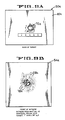
- Figures 11A and 11B illustrates the results of shot 55 which was taken at an oblique angle of 53° by a 105mm warhead against an armor plate 20e without any spall backing material.
- the armor plate 20e indicates that considerable spall was released by the considerable size and depth of the spall cavity 70e.
- the witness plate 54a illustrates a small jet hole 74e with considerable amount of spall spread in a wide angle over the right portion thereof.
Abstract
Description
- The present invention relates to suppression or elimination of spall from being propelled off the inside surface of armor plate used in the armored body of a combat vehicle or the like, by contiguously attaching light weight spall backing material having a sonic impedance such that the stress reflected into the armor is below that which causes lethal spallation in the armor. If the lightweight spall backing does fracture, the resulting spall is comprised of non-lethal fragments of low mass and/or kinetic energy.
- It is well recognized that spall is a primary cause or armor vehicle kills during combat. Spall may be characterized as a cloud of high velocity fragments of metal which is released from the inside surface of the vehicle's armored hull and is lethal to soft targets inside the vehicle. The soft targets include electrical cables, electrical components, fuel lines, fuel cells, and personnel within the vehicle.
- Spall liners are currently being used for minimizing the spall effect but are quite expensive and heavy. The effectiveness of these liners require that the liners be spaced from about 4 to 17 inches from the inner wall of the vehicle and are therefore undesirable since the useable space within most vehicles is quite limited. Also, the hardware within the vehicles makes it difficult or impossible to secure the liner within all portions of the vehicle without interfering with the operation and location of vehicle components. Thus, certain areas of the combat vehicles may not be protected by liners.
- The active spall suppression armor includes an armor material or plate backed by a spall backing material which is contiguously attached to the inside surface of the armor, typically by adhesives. The spall backing material may be of the consistency of pliable putty or may be in the form of hard tiles or sheets. In the event that the spall backing consists of a uniform dispersion of particles in a binder matrix, the matrix binder may serve to contiguously adhere the backing material to the armor. The spall material if fractured, due to excessive stresses transmitted through the armor material, form nonlethal fragments of low mass and kinetic energy. The sonic impedance of the spall material is such that the stress reflected by the spall backing material into the armor is equal to or slightly below that which causes failure in the armor, which failure would result in lethal spall particles being propelled from the inner surface of the metal armor. Spall may be created in the backing material but the effect is minimized by assuring that the spall created in the backing material has low energy and is therefore not lethal. The armor material may be steel armor, aluminum armor, and other types of armor including composite materials.
-
- Figure 1 is a perspective in section illustrating an armor plate without spall backing material attached thereto being impacted by a space charge, or projectile, and showing armor spall being discharged therefrom.
- Figure 2 is a diagrammatic elevation of a military vehicle illustrating a projectile passing through the two armor walls and to spall liners of a prior art vehicle illustrating spall cone angles.
- Figure 3 is a diagrammatic elevation in vertical section illustrating an armor plate with spall backing material attached to a test stand, and a witness sheet attached to a frame.
- Figure 4 is a diagrammatic elevation illustrating a saw-toothed stress wave created in the armor by the impact of a shaped charge explosive at four separate time intervals relative to the free inner surface of the metal armor.
- Figure 5A is a diagram illustrating a saw toothed stress waves at an interface between an armor plate and a backing material having a lower sonic impedance than that of the armor plate.
- Figure 5B is a diagram illustrating the saw-toothed stress waves at an interface between an armor plate and a backing material having a greater sonic impedance than the armor plate.
- Figure 6 is a vertical section taken through an armor plate having a spall backing material contiguously attached thereto by an optional interlayer.
- Figure 7A is a copy of a photograph illustrating the back of an armor test plate without spall backing illustrating the area from which armor spall has been released and further illustrating a hole therein formed by the shaped charge jet.
- Figure 7B is a copy of a photograph illustrating the front of a witness plate illustrating the usual pattern of holes formed therein from spall from the armor plate of Figure 7A and the slug from the shaped charge liner, respectively.
- Figure 8A is a copy of a photograph illustrating the back of an armor test plate for shot 13 (see table 3) with a fully fixed alumina spall backing illustrating the area from which armor spall has been released.
- Figure 8B is a copy of a photograph illustrating the front of the witness plate for shot 13 illustrating a large hole from the slug of the shaped charge liner and a minor spall ring surrounding the slug hole.
- Figure 9A is a copy of a photograph illustrating the back of an armor test plate for
shot 45 having an aluminum-loaded polymer spall backing with indications of very little spall being released. - Figure 9B is a copy of a photograph illustrating the front of the witness plate for
shot 45 having a pair of small holes from fragments of the slug with a small spall ring therearound. - Figure 10A is a copy of a photograph illustrating the back of an armor test plate for shot 46 with an alumina loaded polymer as the backing material showing larger holes from portions of the slug and much smaller holes created by spall fragment from the armor plate.
- Figure 10B is a copy of a photograph of the witness plate of shot 46.
- Figure 11A is a copy of a photograph illustrating the back of an armor test plate that is 1.5 inches thick for shot 55 without backing material protection with the obliquity of the shot being 53 degrees.
- Figure 11B is a copy of a photograph of the witness plate of shot 55.
- Prior to describing the active
spall suppression armor 18 of the present invention, it is believed that a brief description of spallation would be helpful. - Figure 1 diagrammatically illustrates a section of
metal armor 20 without a spall backing material attached thereto, being contacted by aweapon 22 which may be a shaped charge of a high velocity projectile. Theweapon 22 contacts anouter surface 23 of the armor with sufficient force to dislodgespall fragments 24 from the free orinner surface 26 of thearmor 20. The spall fragments are propelled from theinner surface 26 of the armor along a conical path of about 100° at high velocity with many of the fragments being of sufficient mass to be lethal to soft targets that are contacted by the fragments. More particularly, spalling is a failure mode wherein fracture occurs near the free surface 26 (Fig. 1) remote from theouter surface 23 where an impulse load is applied. The impulse load is typically generated by an explosive detonation from a space charge, or by the impact of a high velocity projectile. The impulse induces a compressive shock wave which propagates to the oppositefree surface 26 where it reflects as a tensile wave. The intensity of the tensile wave will increase as it propagates back through the material. At some distance from thesurface 26, the stress intensity exceeds the threshold required for initiation and fracture at which time spallation occurs discharging thespall 24 inwardly at high velocity. - Figure 2 diagrammatically illustrates a vertical section through two
armor plate walls vehicle 30 having two priorart spall liners walls liners wall 28 indicates that thefirst spall liner 32 stops some spall but allows larger high velocity pieces to pass through and be stopped by asecond spall liner 34 as illustrated by a narrowsecondary spall cone 38. - Figure 4 represents stresses caused by shaped charge weapons and illustrates the formation of compressive and tensile waves when passing through the armor at four separate time intervals to the
free surface 26 without spall backing material attached thereto. At time T-1 a saw-tooth wave orpulse 39 illustrates the stress intensity relative to the back orinner surface 26 of the armor caused by the detonation of an explosive. As illustrated at time T-2, when thecompressive wave 39 reaches thefree surface 26 it reflects as atensile wave 42, which is partially cancelled by the incidentcompressive pulse 39. The tensile stress will increase until the maximum stress occurs at a distance from thesurface 26 of theplate 20 equal to one-half of the pulse length as indicated at time T-3. At time T-4 the intensity of the tensile wave exceeds the compressive wave thus indicating that spall will not be created. - When a projectile, as opposed to an explosive detonation or a shaped charge, applies the impact load, a square wave (not shown) is produced which will provide no tensile stress until the maximum occurs at the half pulse distance at T-3 of Figure 3.
- The creation of spall fracture is dependent upon both the magnitude and duration of stress. Sufficient time at the sufficient stress are required to first nucleate cracks, and then to grow the cracks. Fracture is therefore dependent upon amplitude and the shape of the stress pulse. When the condition of stress intensity and time are such that the criterian for fracture are met, then the spall will be formed. When fracture occurs, the strain energy remaining in the material between the fracture and the rear face is released as kinetic energy and the spall particle fly from the rear face, usually with significant velocity. The velocity is limited theoretically by the equation: V = 2M/DC where M is the magnitude of the stress wave, D is the density of the material, and C is the material sound speed.
- When a stress wave encounters an interface between two dissimilar materials such as the armor plate material 20 (Figs. 5A,5B and 6) and the
spall backing material 40, the stress waves behavior becomes more complex. The simplest situation is a normal impact by a projectile with a diameter of the same order of magnitude as the armor plate thickness. The stress wave can then be considered to have a planar front and to travel perpendicular to the face of the plate. In general, when this wave reaches an interface, one wave is reflected and another is transmitted. The intensities of the waves are dependent upon the relative sonic impedances of the two materials. - The sonic impedance (Z) of a material is the product of the sound speed (c) in the material, and its denisty (D). The values of density and sound speed are not constant, but vary to some degree with pressure. Consequently, impedance can vary with the pressure and will definitely change when the yield strength of a material is exceeded. Generally, for most fully dense, elastic materials, the impedance below the yield point is relatively constant. The density, sound speed, and impedance are listed in Table 1 for a number of common materials. The intensities of the transmitted and reflected waves from a stress wave impinging an internal interface are given by the following equations:
-
R = I(D₂ C₂ - D₁ C₁) / (D₂ C₂ + D₁ C₁)
and;
T = I(2D₁ C₁) / (D₂ C₂ - D₁ C₁)
or;
R = I(Z₂-Z₁) / (Z₂ + Z₁)
and;
T = I(2Z₁) / (Z₂ - Z₁)
where;
R = REFLECTED WAVES
T = TRANSMITTED WAVES
I = INCIDENT WAVES
Z = IMPEDANCE OF THE MATERIAL
and where subscript;
1 = the armor material
2 = the spall backing material
- By convention, compressive stress has a positive value and tensile stress has a negative value.
- From the above equations, a compressive wave will reflect as a tensile wave in the armor material if the second layer or backing material has a lower impedance, as illustrated in Figure 5A; and as a compressive wave if the backing material has a higher impedance as illustrated in Figure 5B. The amplitude of the reflected tensile wave will always be less than or equal to that of the incident compressive wave.
- The relative intensity of the reflected wave in the armor material is related to the relative impedance of the spall backing material as follows:
- For an impedance ratio (n) of the armor material the following equations apply: n = Z₂/Z₁
RI = (Z₂ - Z₁) / (Z₂ + Z₁) = nZ₁ - Z₁ / (nZ₁ + Z₁)
or;
RI = (n-1) / (n+1) - This ratio is tabulated in Table 1 to illustrate how a second layer, or backing material 40 (Fig. 6), can be used to reduce the magnitude of the reflected stress. It can be seen that a material with only one fifth of the impedance of the first layer (armor material) can reduce the reflected tensile stress by as much as 33 percent.


- When the spall suppression armor 18 (Fig. 5) of the present invention is to be used on light weight armored vehicles, as well as heavy armored vehicles, it is of course desirable to minimize any added weight to the vehicle. Accordingly, the spall backing material is not designed to completely suppress fractures in the
spall backing material 40 by all known weapons but is designed to provide backing material which, if fractured, will fracture into low energy, non-lethal particles when the armored plate and backing material are contacted by a weapon, either a shaped charge weapon or a projectile. It is, of course, understood that the backing material may be thickened or be in layers of the same or different backing materials if added weight is not a problem. - The concept of the subject invention involves the backing of
armor plate 20 with abacking material 40, or a series of backing materials, which must satisfy two conditions. First, the impedance of the backing material must be such that the stress reflected into thearmor plate 20 is below that which would cause spall-type failure in the armor plate. Second, the fragments from the fracture of the backing material, caused by transmitted stress, must be nonlethal, that is, of low mass and/or velocity. Varying impedance in the backing material may be used to condition the stress wave in the backing material to control fragmentation. The impedance may be varied by either layering or by controlling the material properties continuously through their thicknesses. - A preliminary design analysis was made for identifying the relationship between design variables and system weights. First, the amount of the stress wave which must be transmitted into the spall backing material was estimated by comparing spall strength to the stresses involved in jet penetration. With this data, the properties of the spall backing material was determined.
- The weapons used were shaped charge TOW-II with a jet impacting aluminum armor. A 200 GPa (giga pascals) shock stress was generated with a pulse time length of 1.175 microseconds, which shock stress was calculated from the jet diameter divided by the sound speed in 5083 per MIL-A-46027G(MR) aluminum having a thickness of one inch. It was assumed that the aluminum had about the same spall "strength" as steel, the stress is so much higher in the aluminum than its strength, that essentially the full amplitude of the stress wave must be transmitted into the backing material.
- The relationship between the impedance of the
backing material 40 and the areal density AD required to suppress spall in the aluminum armor was derived as follows:
Let:
Ins = stress pulse wavelength in the backing material
Ial = stress pulse wavelength in the aluminum
cns = wave velocity in the backing material
cal = wave velocity in the aluminum
th = minimum thickness of any backing material for passage of the full stress wave
d = diameter of the shaped charge jet
Dns = density of the backing material
tal = time length of the stress wave in the aluminum
Zns = sonic impedance of the backing material
ADx = minimum areal density of backing material "x" for passage of the full stress wave
The wavelength of the stress pulse in the aluminum armor can be estimated by:
tal = d/cal
Ial = talcal = d
The wavelength in the backing material is:
Ins = Ial(c ns/cal)
Assuming that the backing material will separate from the aluminum when the stress wave reaches the interface after reflecting in tension from the backface of the backing material (because the interface cannot support significant tensile stress), and that conservatively, the whole wave should pass into the backing material:
Ins = 2th or th = (1/2)Ins
Combining the above three equations gives the minimum backing material thickness for any given material:
th = (d/2)cns/cal
The minimum areal density (AD) of the backing system can be calculated as follows:
AD = Dnsth = D ns[(d/2)cns/cal] (Equation 1) = Dnscns[(d/2)cal]
Since Zns =Dnscns:
AD = Zns[(D/2)cal] (Equation 2)
Since the jet diameter, d, and the aluminum wave velocity, cal, are constant for any given case, the minimum areal density of a backing system is linearly related to its impedance. if again it is conservatively assumed that there must be no reflected tensile wave in the aluminum, then the optimum backing material areal density will be when the Impedance of the backing material matches that of the aluminum.
- Assuming a 3/8 inch jet diameter vs. aluminum armor with aluminum as a backing material (matched Impedance), optimum areal density can be calculated as follows: Using equation (1):
ADal = Dal[(d/2)(cal/cal)] = Dal(d/2)
For aluminum, Dns = 14 lb/ft², which yields:
ADal = 2.625 lb/ft²
The fired alumina, which worked well in the preliminary testing, would yield an optimum from equation (2) (considering that Zalumina/Zal = 2.33):
ADalumina = 2.625(2.33) = 6.116 lb/ft²
The above calculations indicate that aluminum would be a lighter backing material than the fully fired alumina. However, the aluminum is not frangible. While the aluminum backing material would successfully extract the stress wave from the aluminum armor plate or hull structure of a vehicle, the aluminum backing material could itself produce lethal spall.
Therefore, considering both areal density and fracture considerations, the optimum backing material could be either a pure, ductile spall resistant aluminum, or an alumina body with sufficient porosity introduced to bring its impedance down to that of aluminum. The backing material should be bonded to the hull or armor plate using a tough adhesive with relatively thin bond lines. - This design methodology also suggests the merits of a metallic or ceramic particle loaded polymer. In this case, the individual particles have a higher sonic impedance than that of the armor. However, when the particles are combined with a polymer, the particle content must be sufficient to insure that the particle/polymer blend has a sonic impedance equal to or greater than the armor plate. A particle/polymer blend may also afford the advantage of sticking directly to the armor without the need of an intermediate adhesive.
- A low density strength solid which fractures in a brittle manner, and which has a suitable impedance, may also be used. For instance, solid, polycrystalline sodium chloride (NaCl) in a 1/2 inch thickness has suppressed spall formation in aluminum armor when bonded to the back of the armor plate.
- Tests have been conducted to investigate the effect of spall backing material thickness, warhead size, obliquity, armor alloy, and armor thickness on the performance of the various backing materials. The general procedure consists of adhesively bonding the backing material 40 (Fig. 6) to the
armor plate 20 which together comprise a piece of active spallsuppressive armor 18 in the form of a target 50 (Fig. 3). The target is fixed to a test stand 52, and thetarget 50 and awitness sheet 54 are subjected to a warhead attack. Base line targets of unbacked and liner-backed armor plates were also tested for comparison purposes. Thewitness sheets 54 were placed behind the test stand to record the distribution of spall and jet particles. The test matrix of the shots are illustrated in Table 3.


- The spall backing material used in the tests included:
- 1. Unfired alumina
- 2. Bisque-fired alumina
- 3. Fully fired alumina
- 4. 1100 aluminum
- 5. ALP (an alumina-loaded epoxy);
- The primary backing materials are either readily commercially available or easily producable and are described in detail below.
Fully-fired alumina - density: 3.46 g/cc or 17.9 PSF per inch of thickness. This material was procured as 87% pure alumina. This is a fully-dense alumina, marketed for wear resistant applications. Plates and hexagonal tiles were used. The plates were nominally 6" x 4" x 1/2" or 4" x 4" x 1/4". The hex tiles, 7/8" across the flats and 3/8" thick, were supplied bonded to a plastic net in 6" x 6" sections.
Unfired alumina - density: 2.18 g/cc or 11.3 PSF per inch of thickness. This material is of the same composition as the fully-fired alumina. The unfired alumina is not used for any commercial application, being a fully-fired alumina body in an intermediate state of manufacture. The unfired body consists of a micron range powder pressed into a compact plate with an organic binder (generally about 2%).
Bisque-fired alumina - density: 2.07 g/cc or 10.7 PSF per inch of thickness. Similar to the unfired alumina, this material is a body in what would typically be an intermediate stage of manufacture. The bisque firing is done at a relatively low temperature, which first burns off the organic binder, and then bonds the alumina particulates by melting the glass components in the powder.
1100 aluminum - density 2.71 g/cc or 14.0 PSF per inch of thickness. This aluminum alloy was selected as one having matching Impedance to the aluminum armor, but with high ductility and elongation to failure. Additionally, this is a very pure alloy of a minimum of 99% aluminum. The high purity eliminates most of the second phase particles associated with high strength aluminum alloys, which have been identified in some research as being nucleation sites for spall cracks. It was anticipated that this high purity alloy might then be less spall prone than thehigh strength 5083 and 7039 alloys.
Alumina-loaded polymer (ALP) - density: 2.05 g/cc or 10.6 PSF per inch of thickness. - ALP, a readily available commercial material, was tested and is a wear resistant coating material consisting of a 70% by weight concentration of alumina beads suspended in an epoxy resin. The beads are of an 87%. Particulate analysis shows that the beads have an average particle size of about 440 microns. Particles are porous and polycrystaline, with micron-size alpha alumina crystalites in a glass matrix.
- As indicated in Table 3, the majority of ballistic tests were made with 7039 aluminum armor alloy since it is considerably more spall prone than 5083 aluminum armor alloy which was also tested. The angle of attack or obliguities were usually perpendicular to the outer wall of the test target which is indicated as 0° in Table 3 although several tests were made at 53°. The thickness of the armor targets was usually 1 inch although several tests were made with targets that were 1.5 inches thick. The aluminum armor alloys were of armor specification; MIL-A-46027G (MR) for 5083 aluminum, and MIL-A-46063F for 7039 aluminum.
- Four
shots Shots 21 and 38 were made with the spall liner panels clamped directly to the armor plate, shot 58 had the liner panel spaced four inches off the back of the armor plate, and shot 59 was made with the liner panel as a secondary backing material layer behind a layer of fully fired alumina. - A basic premise of the several preferred types of backing material is that the backing material works best when in direct or contiguous contact with the interior of the armor plate, whereas tests indicate that conventional spall liners require a stand-off space to work efficiently. When a conventional spall liner is used in contact with the armor plate, it has been found that a considerably thicker, and thus a weight penalty, is required to achieve the same performance. The weight of the conventional liners for shot No. 58 was 8 pounds per square foot consisting of two layers, whereas shot No. 59 consisting of a single panel spaced four inches from the back of the armor plate weighed four pounds per square foot.
-
Tests - Before each of the above tests were conducted when using armor plate with fully fired, unfired and bisque-fired aluminas, or the 1100 aluminum, the mating surfaces of the armor plate and the backing material were thoroughly cleaned and flattened using sand paper or the like, and an appropriate amount of epoxy was mixed and evenly applied to the backing plate and attached to the armor plate in a manner which eliminated all air pockets therefrom. The panels were then allowed to cure for fifteen minutes.
- The procedure for applying alumina loaded epoxy to the armor was similar except that the alumina loaded epoxy was mixed at a ratio of 1 part by volume of hardener to 16 parts of powdered resin/alumina paste. One gallon of the mix covered 6 targets with a 3/8 inch thick section. This mixture was then placed in plywood molds on the armor plate and pressed flat with a 12" x 12" metal plate having waxed paper between the plate and the mixture. The plate is then slid off the mixture and the mixture is secured overnight at a temperature above 60°F.
- The following warheads used during the test were not production rounds but were rounds rejected for minor-out-of specification conditions.
- 1. TOW II Simulants
- 2. BRL 3.2¨ Simulants
- 3. 105mm (In production form known as M456 Heat rounds)
- The above warheads are all of the shaped charge type which produce a slug in addition to a jet. The slug forms from the cone material which remains after the jet forms and has significant mass and velocity and may pass through the armor plate and backing.
- During the ballistic test, the
armor plate 20 andbacking material 40 bonded thereto were clamped to the front face of the rigid 3¨ steel test stand 52 (Fig. 3) to which an 18" or 24"square armor plate 20 is clamped with thebacking material 40 projecting into an elipitical cut-out 53 in the steel test stand 52. Witnesssheets 54 are clamped to aframe 56 which is parallel to the test stand 52 and is 24" square for the 0° obliguity shots and 4' x 8' for the 53° obliguity shots. As illustrated in Table 3,aluminum witness sheets 54 were used in most of the early tests having a thickness of 20 mill's. Inlater tests 24 mill soft steel sheets were used because the aluminum witness plates would deform excessively and it was desired to more closely differentiate between lethal and nonlethal spall. The witness sheets were supported by two 3/8" plywood sheets (not shown). - In an initial tests conducted with a TOW II warhead the impact of the slug tore a large hole in the
target plate 20 and broke it in half. In order to overcome this problem, a steel stripper plate 58 (Fig. 3) with a 2 1/2"diameter hole 60 therein was placed between the warhead and the witness sheet to prevent the slug from impacting the witness sheet. The hole in thestripper plate 58 was subsequently decreased in size to 1 3/4" since the larger hole was not consistently stopping the slug. Even the smaller hole was insufficient to eliminate the slug impact damage completely. - Ballistic tests were conducted specifically in regard to three functions; the primary function being to suppress spall in the armor plate, the second function being the production of nonlethal fragments from the spall backing material itself, and the third function being the evaluation of the effect of different types of spall backing material on the jet penetration process from spaced charge warheads. The results of the tests were expedited by photographing the front and back of each target and the front of each witness sheet with back lighting. The many photographs were then easily compared to determine which backing materials and thicknesses were most effective to prevent or minimize lethal spall from the armor and nonlethal spall from the backing material.
- In comparing the witness sheets from unbacked targets and targets backed with spall backing material, the witness sheets from unbacked targets shot at 0° obliguity typically exhibited two features; a central region of perforations caused by the passage of the jet from a spaced charge, and surrounding this, a generally circlar distribution of perforations as illustrated in Figure 7B from 105mm shot 48. Figure 7A illustrates the back of the target and the zone from which spall was released. The specifics of the shot are given in Table 6.
- The witness sheets and target from oblique shots of unbacked targets exhibit three features; the jet penetration region, a lobe of penetration in the plane of the jet, and an arc of penetration around te jet zone. Figure 8A illustrates the back of the armor plate from which spall has been released. Figure 8B illustrates the witness plate from 105mm shot 13 with the jet penetration hole and the arc of penetration of the armor spall being shown. The numerical data of all tests in which witness plates were used is shown in Table 6 with the identification number, i.e., shot No., corresponding to those in Table 3.


- The data was evaluated in regard to the intended functions of the spall backing material which is the suppression of spall forming in the armor plate material, and the production of nonlethal fragments from the spall backing materials. While no one material was demonstrated to be best in all cases, definite trends in performance were observed that are linked to the different materials. These trends are as follows:
- The tests with 1100 aluminum demonstrated its ability to completely suppress the formation of spall in the armor plate. Since the spall strength is the stress level at which void nucleation occurs prior to spall fracture, and since the impedance of the aluminum backing material was equal to that of the armor material spallation will not occur.
- It was observed that there is a limited thickness of the spall backing material below which the backing system will not function. For instance, while the 1100 aluminum backing material at 0.5" thick completely eliminated the formation of spall, a 0.19" layer allowed spall to form in the armor plate.
- The nature of the damage to the witness sheet from the targets backed by ceramic materials is different from the others. Much of the damage to the witness sheet from the ceramic targets appeared as "burn holes" which generally exhibited a blackened, raised edge on both the front and rear of the witness plates. The perforations holes in the unbacked or aluminum-backed targets are irregular in shape and have a lip surrounding the hole only at the exit side. A steel plate in Test No. 49 gave indications that particles causing the burn holes are both copper and aluminum. It is assumed that the copper jet tip and the target material (aluminum) were entrained in the jet as it is discharged from the armor plate and is dispersed by the ceramic materials.
- Burn holes occurred from all of the ceramic-backed targets except for the first two ALP targets in
tests 37 and 39. The ALP on these two targets had mistakenly been made with less than the specific amount of the hardener, reducing the bond strength of the epoxy compared to the fully cured material. Witness sheets from later fully cured ALP samples exhibited burn holes. In addition, the witness sheets from the fully fired alumina-backed samples generally showed a greater density and distribution of the burn holes than did those from the unfired or bisque-fired alumina-backed samples. The indication is that higher strength in a ceramic system tends to increase the interaction with the jet. - Table 7 shows a break down of the tests grouped into those of similar warhead, armor type, and obliguity, and then ranked according to increasing penetration hole volume. For the 0° obliguity tests, the addition of the backing material generally leads to a significant decrease in the penetration hole volume compared to unbacked targets. The ALP material was an anomaly in its unusually good performance in the 3.2" weapon tests.


- Table 8 is similar to Table 7 except that the tests are ranked in order of increasing spall volume. In many cases it can be seen that the ALP, fully fired alumina and 1100 aluminum completely suppressed formation of spall. Even when the spall was not fully suppressed these materials performed consistently better than the unfired or bisque-fired aluminas. This is not an unexpected result in that the materials rank in order of their known or expected impedance values.


- Table 9, again similar to table 7, ranks the tests according to the diameter containing 99% of the spall damage on the witness sheet. It should first be noted that this diameter actually includes all of the damage to the witness whether from armor spall, backing material fragments, or jet particles. Again the ALP and fully-fitted alumina are noted to be the most consistent performers, the ALP the more notable of the two. The unfired alumina also exhibited good performance. The very good performance of the fully-fired alumina was somewhat unexpected since its strength and density are so much higher than the unfired and bisque-fired materials. The reason for the results may be that the higher strength allowed more strain energy to be stored prior to failure. This energy would then be released in the formation of more surface (therefore more fragments of smaller size). This is seen in flexure testing of ceramics where materials with higher strength tend to break up into more fragments than those with lower strength.
- Against all rounds tested the material which has been most effective in suppressing lethal spall is ALP. This material was exceptional in all aspects against a 3.2" warhead. Against the other heads it showed a very good performance. The other resin matrix backing materials tested well when fully cured.
- Although the spall backing materials used in a ballistic test included only ALP; fully-fired, bisque-fired, and unfired alumina; and 1100 aluminum at the thicknesses set forth in the several tables, it will be understood that other materials may be used as backing materials over armor plate.
- For example, steel fibers or powders, or fibers or powders from other metals, may be added to the micron range alumina powders along with an organic binder when making the backing material. Furthermore, the backing material may include composite fibers or woven composite cloth having the desired impedance. As illustrated in Figure 6, the optional interlayer of EPDM, which is an uncured rubber, or a cloth plus adhesive, or any other suitable bonding material may be used between the backing material and armor to more readily apply the backing material contiguously to the armor. In addition, the consistency of the backing material may be in the form of hard tiles or plates, depending upon the type of armor surface to which they are to be applied, or may be of relatively soft consistency such as putty which can be easily adhered to corners and curved surfaces of the armor being protected from spallation.


- Figures 7A and 7B illustrate the results of test shot No. 48. An
armor plate 20a, without spall backing material, indicates that a substantial amount of spall was released from theinner face 26a by the cross-sectional area of aspall cavity 70a as compared to thehole 72a formed by the jet of the 105mm spaced charge weapon. The scale on the armor plates in Figures 7A, 8A, 9A and 11 are all in inches. Figure 7B illustrates that thewitness plate 54a was perforated by the jet at 74a and by a fragment of the copper jet tip (not shown) of the weapon at 76a. A ring ofholes 78a indicate that a large amount of lethal spall was propelled through thewitness plate 54a. - Figures 8A and 8B illustrate the results of test shot No. 13. The armor plate had a 0.50 thick fully-fired alumina
spall backing material 40b secured thereto. ATOW 11 weapon was used making alarger hole 72b through the target with much less and much finer spall being propelled therethrough as indicated by thehole 72b and thespall cavity 70b in the spall backing material. Thealuminum witness plate 54b indicates that a very large hole 74b was apparently caused by a portion of the slug and by burning therethrough by the jet, but that very small particles of backing material spall contacted the aluminum witness plate at 78b doing little damage. - Figures 9A and 9B illustrate the results of test shot 45. The
armor plate 20c had a 0.38 inchALP backing material 40c bonded thereto which minimized release of spall from the armor material as indicated by thehole 72c and primarily directed nonlethal backing material spall against thewitness plate 54c as indicated at 78c. The warhead was a 105mm spaced charge. - Figures 10A and 10B illustrates the results of test shot 46 by a
TOW 11 against anarmor plate 20d having a 0.38 inchALP backing material 40d bonded thereto. The steelarmor plate witness 54d indicated some spall damage, indicting that the thickness of the backing material should be increased for theTOW 11 weapon. - Figures 11A and 11B illustrates the results of shot 55 which was taken at an oblique angle of 53° by a 105mm warhead against an armor plate 20e without any spall backing material. The armor plate 20e indicates that considerable spall was released by the considerable size and depth of the
spall cavity 70e. Thewitness plate 54a illustrates asmall jet hole 74e with considerable amount of spall spread in a wide angle over the right portion thereof. - From the foregoing description it will be apparent that several types of backing material have been disclosed and tested for preventing or suppressing warhead induced formations of lethal spall. If the impedance of the armor material is the same or less than the impedance of the backing material, the formation of lethal armor spall will be prevented. If the armor and backing material are used in a vehicle and the total weight of the vehicle must be minimized for improving performance, the thickness of the backing material may be reduced to minimize the increase in weight causing the impedance of the backing material to becomes less than that of the armor material. Depending upon the thickness of the backing material, lethal armor spall with potential for some damage and nonlethal backing material spall may be formed and distributed in a narrow cone angle within the vehicle depending upon the impact delivered by the warhead contacting the armor.
- Although the best mode contemplated for carrying out the present invention has been herein shown and described it will be apparent that modification and variation may be made without departing from what is regarded to be the subject matter of the invention.
Claims (55)
means defining spall backing material formed from materials which if fractured due to stresses transmitted through the metal armor form nonlethal fragments of low mass and kinetic energy, said spall backing material having a sonic impedance such that the stress reflected into the armor by the backing material at least suppresses the formation of spall in the armor; and
means for contiguously securing the spall backing material to said inside surface.
means defining spall backing material formed from materials which if fractured due to stresses transmitted through the metal armor form nonlethal fragments of low mass, said spall backing material having a sonic impedance such that the stress reflected into the armor by the backing material at least supresses the formation of spall in the armor; and
means for contiguously securing the spall backing material to said inside surface.
means defining spall backing material formed from materials which if fractured due to stresses transmitted through the metal armor form nonlethal fragments of low kinetic energy, said spall backing material having a sonic impedance such that the stress reflected into the armor by the backing material at least suppressed the formation of spall in the armor; and
means for contiguously securing the spall backing material to said inside surface.
means defining a spall backing material having a sonic impedance sufficient to reduce the amplitude of a reflected stress wave in the armor from contact by the warhead; and
means for securing the backing material to said metallic armor in position to assure that the stress wave in the metallic armor is adequately reflected.
contiguously securing a spall backing material to said one surface of said armor plate; and
forming the spall backing material from materials which are bonded together in a shape which conforms to that of said one surface and which has a sonic impedance such that stress transmitted into said backing material from said armor plate is reflected into the armor plate and will suppress lethal spall from being propelled from said armor.
an alumina-loaded polymer formed with about 80% pure alumina into a fully fired fully dense alumina having a density of about 17.9 pounds per square foot per inch thickness, said polymer when fractured due to stresses transmitted therethrough forming nonlethal spall fragments of low mass.
Priority Applications (1)
| Application Number | Priority Date | Filing Date | Title |
|---|---|---|---|
| AT88113787T ATE102339T1 (en) | 1987-09-18 | 1988-08-24 | ARMOR PLATE FOR HOLDING DOWN A SPILL OPERATIONS. |
Applications Claiming Priority (2)
| Application Number | Priority Date | Filing Date | Title |
|---|---|---|---|
| US98633 | 1987-09-18 | ||
| US07/098,633 US4934245A (en) | 1987-09-18 | 1987-09-18 | Active spall suppression armor |
Publications (2)
| Publication Number | Publication Date |
|---|---|
| EP0307672A1 true EP0307672A1 (en) | 1989-03-22 |
| EP0307672B1 EP0307672B1 (en) | 1994-03-02 |
Family
ID=22270217
Family Applications (1)
| Application Number | Title | Priority Date | Filing Date |
|---|---|---|---|
| EP88113787A Expired - Lifetime EP0307672B1 (en) | 1987-09-18 | 1988-08-24 | Active spall suppression armor |
Country Status (9)
| Country | Link |
|---|---|
| US (1) | US4934245A (en) |
| EP (1) | EP0307672B1 (en) |
| KR (1) | KR950001998B1 (en) |
| AT (1) | ATE102339T1 (en) |
| AU (1) | AU611194B2 (en) |
| CA (1) | CA1307686C (en) |
| DE (1) | DE3888059T2 (en) |
| IL (1) | IL87775A (en) |
| TR (1) | TR24164A (en) |
Cited By (2)
| Publication number | Priority date | Publication date | Assignee | Title |
|---|---|---|---|---|
| EP0334263A1 (en) * | 1988-03-23 | 1989-09-27 | Fmc Corporation | Improved active spall suppression armor |
| EP0588212A1 (en) * | 1992-09-17 | 1994-03-23 | Fmc Corporation | Advanced spall liner system |
Families Citing this family (22)
| Publication number | Priority date | Publication date | Assignee | Title |
|---|---|---|---|---|
| FR2727508B1 (en) * | 1994-11-30 | 1997-01-17 | Giat Ind Sa | CHIPPING COVER FOR ARMORED VEHICLE |
| US5970843A (en) * | 1997-05-12 | 1999-10-26 | Northtrop Grumman Corporation | Fiber reinforced ceramic matrix composite armor |
| US6253655B1 (en) | 1999-02-18 | 2001-07-03 | Simula, Inc. | Lightweight armor with a durable spall cover |
| US7562612B2 (en) * | 2001-07-25 | 2009-07-21 | Aceram Materials & Technologies, Inc. | Ceramic components, ceramic component systems, and ceramic armour systems |
| ES2361676T3 (en) * | 2001-07-25 | 2011-06-21 | Aceram Materials And Technologies Inc. | SHIELDING PLATE WITH COVERING COATS. |
| CA2483231C (en) * | 2004-09-30 | 2011-11-29 | Aceram Technologies Inc. | Ceramic armor system with diamond coating |
| EP1883779A2 (en) * | 2005-05-26 | 2008-02-06 | Composix Co. | Ceramic multi-hit armor |
| IL170004A (en) * | 2005-08-01 | 2013-03-24 | Rafael Advanced Defense Sys | Ceramic armor against kinetic threats |
| US20090217811A1 (en) * | 2006-01-17 | 2009-09-03 | David William Leeming | Textile armour |
| US20070293107A1 (en) * | 2006-06-14 | 2007-12-20 | Hexcel Corporation | Composite assembly and methods of making and using the same |
| US7703375B1 (en) * | 2006-08-15 | 2010-04-27 | Lawrence Technological University | Composite armor with a cellular structure |
| US8689671B2 (en) | 2006-09-29 | 2014-04-08 | Federal-Mogul World Wide, Inc. | Lightweight armor and methods of making |
| NL2000406C2 (en) * | 2006-12-22 | 2008-06-24 | Tno | Method and device for protecting objects against rocket-driven grenades (RPGs). |
| US8434396B1 (en) | 2007-07-23 | 2013-05-07 | Verco Materials, Llc | Armor arrangement |
| WO2011123086A1 (en) * | 2008-01-23 | 2011-10-06 | Force Protection Technologies, Inc. | Multilayer armor system for defending against missile-borne and stationary shaped charges |
| US8132495B2 (en) | 2008-01-23 | 2012-03-13 | Force Protection Technologies, Inc. | Multilayer armor system for defending against missile-borne and stationary shaped charges |
| US20090293709A1 (en) * | 2008-05-27 | 2009-12-03 | Joynt Vernon P | Apparatus for defeating high energy projectiles |
| NL2002952C2 (en) * | 2009-06-02 | 2010-12-07 | Koster Rudy Hendrik Gerard | Armour, in particular passive armour, use of a compound in an armour and a method for manufacturing an armour. |
| US9500445B2 (en) * | 2013-09-10 | 2016-11-22 | The United States Of America As Represented By The Secretary Of The Army | Multi-layer matrix composite having improved energy absorption, dissipation and shock wave mitigation capabilities |
| WO2016054625A2 (en) * | 2014-10-03 | 2016-04-07 | Antiballistic Security And Protection, Inc. | Structural materials and systems |
| US9835429B2 (en) * | 2015-10-21 | 2017-12-05 | Raytheon Company | Shock attenuation device with stacked nonviscoelastic layers |
| US10260272B1 (en) * | 2017-03-01 | 2019-04-16 | David Ivester | Indoor safety shelter for protection from intruders |
Citations (12)
| Publication number | Priority date | Publication date | Assignee | Title |
|---|---|---|---|---|
| US2391353A (en) * | 1941-12-04 | 1945-12-18 | Hiram W Sheridan | Armor |
| GB746371A (en) * | 1950-09-23 | 1956-03-14 | Us Rubber Co | Improvements in protective structure |
| US3444033A (en) * | 1964-06-22 | 1969-05-13 | Aerojet General Co | Lightweight armor with laminated base member resistant to delamination |
| FR1581760A (en) * | 1968-07-31 | 1969-09-19 | ||
| US3592147A (en) * | 1969-05-14 | 1971-07-13 | Lockheed Aircraft Corp | Method and means for attenuating shock waves propagating within a solid |
| DE2035953A1 (en) * | 1970-07-20 | 1972-02-03 | Kohlensaurewerke CG. Rommenholler GmbH, 3491 Herste | Light-weight energy dissipating panels - epoxide resin panels with metal powder inclusions |
| US3771418A (en) * | 1971-09-29 | 1973-11-13 | Us Army | Anti-spall lightweight armor |
| US4061815A (en) * | 1967-10-26 | 1977-12-06 | The Upjohn Company | Novel compositions |
| FR2428226A1 (en) * | 1978-06-06 | 1980-01-04 | Saint Louis Inst | Laminated armour plate with low tendency to delaminate and splinter - composed of outer steel ply, various intermediate metal plies and polyethylene backing |
| US4300439A (en) * | 1979-09-10 | 1981-11-17 | United Technologies Corporation | Ballistic tolerant hydraulic control actuator and method of fabricating same |
| US4664967A (en) * | 1986-04-21 | 1987-05-12 | The United States Of America As Represented By The Secretary Of The Army | Ballistic spall liner |
| US4704943A (en) * | 1981-06-15 | 1987-11-10 | Mcdougal John A | Impact structures |
Family Cites Families (21)
| Publication number | Priority date | Publication date | Assignee | Title |
|---|---|---|---|---|
| US2036903A (en) * | 1934-03-05 | 1936-04-07 | Norton Co | Cutting-off abrasive wheel |
| US2372607A (en) * | 1940-11-23 | 1945-03-27 | American Electro Metal Corp | Method of making layered armors |
| US2922483A (en) * | 1954-06-03 | 1960-01-26 | Harris Transducer Corp | Acoustic or mechanical impedance |
| US2861021A (en) * | 1956-12-13 | 1958-11-18 | Albert G H Dietz | Transparent protective shield |
| US3013904A (en) * | 1959-04-13 | 1961-12-19 | Du Pont | Substrate having an organic polymer containing pentavalent phosphorus bonded thereto |
| US3705558A (en) * | 1963-04-24 | 1972-12-12 | Gen Motors Corp | Armor |
| US3634177A (en) * | 1966-11-01 | 1972-01-11 | Gen Electric | Lightweight transparent penetration-resistant structure |
| US3649426A (en) * | 1967-12-22 | 1972-03-14 | Hughes Aircraft Co | Flexible protective armour material and method of making same |
| GB1318351A (en) * | 1968-05-06 | 1973-05-31 | Norton Co | Composite armour |
| US3969563A (en) * | 1969-08-28 | 1976-07-13 | Hollis Sr Russell E | Protective wall structure |
| DE2051970C1 (en) * | 1970-10-22 | 1978-10-19 | Blohm + Voss Ag, 2000 Hamburg | Method for producing a neutron shield |
| US3962976A (en) * | 1971-08-16 | 1976-06-15 | Aluminum Company Of America | Composite armor structure |
| DE2201637A1 (en) * | 1972-01-14 | 1973-08-02 | Hans Dr Hendrix | Bullet proof tank plate - with steel fibre felt and polyurethane foam core between steel sheets |
| US4042559A (en) * | 1972-03-23 | 1977-08-16 | The Carborundum Company | Abrasion resistant coated abrasive pipe lining sheet |
| US4012549A (en) * | 1974-10-10 | 1977-03-15 | General Dynamics Corporation | High strength composite structure |
| US4030427A (en) * | 1974-10-30 | 1977-06-21 | The United States Of America As Represented By The Secretary Of The Navy | Armor plate |
| US4186648A (en) * | 1977-06-07 | 1980-02-05 | Clausen Carol W | Armor comprising ballistic fabric and particulate material in a resin matrix |
| DE2744905A1 (en) * | 1977-10-06 | 1979-04-12 | Wahl Verschleiss Tech | Armour plate capable of resisting piercing projectiles - is weldable steel plate covered with carbide forming alloy deposit |
| US4241457A (en) * | 1978-04-26 | 1980-12-30 | Klein John M | Energy impact dissolution and trauma reduction device |
| GB2149482B (en) * | 1981-08-13 | 1986-02-26 | Harry Apprich | Projectile-proof material |
| DE3508848A1 (en) * | 1985-03-13 | 1986-09-25 | M A N Technologie GmbH, 8000 München | Armour element |
-
1987
- 1987-09-18 US US07/098,633 patent/US4934245A/en not_active Expired - Lifetime
-
1988
- 1988-08-23 CA CA000575460A patent/CA1307686C/en not_active Expired - Lifetime
- 1988-08-24 AT AT88113787T patent/ATE102339T1/en not_active IP Right Cessation
- 1988-08-24 EP EP88113787A patent/EP0307672B1/en not_active Expired - Lifetime
- 1988-08-24 DE DE3888059T patent/DE3888059T2/en not_active Expired - Fee Related
- 1988-09-02 AU AU21850/88A patent/AU611194B2/en not_active Ceased
- 1988-09-15 TR TR88/0663A patent/TR24164A/en unknown
- 1988-09-16 IL IL87775A patent/IL87775A/en not_active IP Right Cessation
-
1989
- 1989-09-16 KR KR1019880011949A patent/KR950001998B1/en not_active IP Right Cessation
Patent Citations (12)
| Publication number | Priority date | Publication date | Assignee | Title |
|---|---|---|---|---|
| US2391353A (en) * | 1941-12-04 | 1945-12-18 | Hiram W Sheridan | Armor |
| GB746371A (en) * | 1950-09-23 | 1956-03-14 | Us Rubber Co | Improvements in protective structure |
| US3444033A (en) * | 1964-06-22 | 1969-05-13 | Aerojet General Co | Lightweight armor with laminated base member resistant to delamination |
| US4061815A (en) * | 1967-10-26 | 1977-12-06 | The Upjohn Company | Novel compositions |
| FR1581760A (en) * | 1968-07-31 | 1969-09-19 | ||
| US3592147A (en) * | 1969-05-14 | 1971-07-13 | Lockheed Aircraft Corp | Method and means for attenuating shock waves propagating within a solid |
| DE2035953A1 (en) * | 1970-07-20 | 1972-02-03 | Kohlensaurewerke CG. Rommenholler GmbH, 3491 Herste | Light-weight energy dissipating panels - epoxide resin panels with metal powder inclusions |
| US3771418A (en) * | 1971-09-29 | 1973-11-13 | Us Army | Anti-spall lightweight armor |
| FR2428226A1 (en) * | 1978-06-06 | 1980-01-04 | Saint Louis Inst | Laminated armour plate with low tendency to delaminate and splinter - composed of outer steel ply, various intermediate metal plies and polyethylene backing |
| US4300439A (en) * | 1979-09-10 | 1981-11-17 | United Technologies Corporation | Ballistic tolerant hydraulic control actuator and method of fabricating same |
| US4704943A (en) * | 1981-06-15 | 1987-11-10 | Mcdougal John A | Impact structures |
| US4664967A (en) * | 1986-04-21 | 1987-05-12 | The United States Of America As Represented By The Secretary Of The Army | Ballistic spall liner |
Cited By (3)
| Publication number | Priority date | Publication date | Assignee | Title |
|---|---|---|---|---|
| EP0334263A1 (en) * | 1988-03-23 | 1989-09-27 | Fmc Corporation | Improved active spall suppression armor |
| EP0588212A1 (en) * | 1992-09-17 | 1994-03-23 | Fmc Corporation | Advanced spall liner system |
| US5402703A (en) * | 1992-09-17 | 1995-04-04 | Fmc Corporation | Liner system to reduce spall |
Also Published As
| Publication number | Publication date |
|---|---|
| EP0307672B1 (en) | 1994-03-02 |
| AU611194B2 (en) | 1991-06-06 |
| IL87775A0 (en) | 1989-03-31 |
| AU2185088A (en) | 1989-03-23 |
| DE3888059T2 (en) | 1994-07-07 |
| ATE102339T1 (en) | 1994-03-15 |
| US4934245A (en) | 1990-06-19 |
| DE3888059D1 (en) | 1994-04-07 |
| CA1307686C (en) | 1992-09-22 |
| IL87775A (en) | 1991-09-16 |
| TR24164A (en) | 1991-04-26 |
| KR950001998B1 (en) | 1995-03-08 |
| KR890005487A (en) | 1989-05-15 |
Similar Documents
| Publication | Publication Date | Title |
|---|---|---|
| EP0307672B1 (en) | Active spall suppression armor | |
| US6698331B1 (en) | Use of metal foams in armor systems | |
| Kaufmann et al. | Influence of material properties on the ballistic performance of ceramics for personal body armour | |
| Madhu et al. | An experimental study of penetration resistance of ceramic armour subjected to projectile impact | |
| CA2188604C (en) | Armouring | |
| Wilkins | Third progress report of light armor program | |
| Boldin et al. | Review of ballistic performance of alumina: Comparison of alumina with silicon carbide and boron carbide | |
| USH1061H (en) | Composite shields | |
| EP1737653A2 (en) | Armor including a strain rate hardening elastomer | |
| US10197363B1 (en) | Porous refractory armor substrate | |
| US20120055327A1 (en) | Armor system having ceramic matrix composite layers | |
| Andraskar et al. | Impact response of ceramic structures-A review | |
| EP0334263B1 (en) | Improved active spall suppression armor | |
| EP1078215B1 (en) | Use of metal foams in armor systems | |
| US6474213B1 (en) | Reactive stiffening armor system | |
| US8176829B1 (en) | Armor system and method of manufacture | |
| Wilkins | Use of boron compounds in lightweight armor | |
| CA2012552A1 (en) | Armour | |
| JINNAPAT et al. | Ballistic performance of composite armor impacted by 7.62 mm armor projectile | |
| Ogorkiewicz | Composite armour | |
| RU193794U1 (en) | COMPOSITE PULSE PROTECTIVE ARMOR PANEL FOR ARMORED VEST | |
| Ślęzak | Employment of the new advanced structural materials in the military vehicles and heavy equipment | |
| Odanović et al. | Ballistic protection efficiency of composite ceramics/metal armours | |
| Diederen et al. | Ballistic protection against armour piercing projectiles using titanium base armour | |
| Jagannathan | Energy partitioning in ballistic impact fragmentation of titanium boride |
Legal Events
| Date | Code | Title | Description |
|---|---|---|---|
| PUAI | Public reference made under article 153(3) epc to a published international application that has entered the european phase |
Free format text: ORIGINAL CODE: 0009012 |
|
| AK | Designated contracting states |
Kind code of ref document: A1 Designated state(s): AT BE CH DE ES FR GB GR IT LI LU NL SE |
|
| 17P | Request for examination filed |
Effective date: 19890724 |
|
| 17Q | First examination report despatched |
Effective date: 19910122 |
|
| GRAA | (expected) grant |
Free format text: ORIGINAL CODE: 0009210 |
|
| AK | Designated contracting states |
Kind code of ref document: B1 Designated state(s): AT BE CH DE ES FR GB GR IT LI LU NL SE |
|
| PG25 | Lapsed in a contracting state [announced via postgrant information from national office to epo] |
Ref country code: IT Free format text: LAPSE BECAUSE OF FAILURE TO SUBMIT A TRANSLATION OF THE DESCRIPTION OR TO PAY THE FEE WITHIN THE PRE;WARNING: LAPSES OF ITALIAN PATENTS WITH EFFECTIVE DATE BEFORE 2007 MAY HAVE OCCURRED AT ANY TIME BEFORE 2007. THE CORRECT EFFECTIVE DATE MAY BE DIFFERENT FROM THE ONE RECORDED.SCRIBED TIME-LIMIT Effective date: 19940302 Ref country code: NL Effective date: 19940302 Ref country code: GR Free format text: LAPSE BECAUSE OF FAILURE TO SUBMIT A TRANSLATION OF THE DESCRIPTION OR TO PAY THE FEE WITHIN THE PRESCRIBED TIME-LIMIT Effective date: 19940302 Ref country code: ES Free format text: THE PATENT HAS BEEN ANNULLED BY A DECISION OF A NATIONAL AUTHORITY Effective date: 19940302 Ref country code: BE Effective date: 19940302 |
|
| REF | Corresponds to: |
Ref document number: 102339 Country of ref document: AT Date of ref document: 19940315 Kind code of ref document: T |
|
| REF | Corresponds to: |
Ref document number: 3888059 Country of ref document: DE Date of ref document: 19940407 |
|
| ET | Fr: translation filed | ||
| NLV1 | Nl: lapsed or annulled due to failure to fulfill the requirements of art. 29p and 29m of the patents act | ||
| PG25 | Lapsed in a contracting state [announced via postgrant information from national office to epo] |
Ref country code: LU Free format text: LAPSE BECAUSE OF NON-PAYMENT OF DUE FEES Effective date: 19940831 |
|
| PLBE | No opposition filed within time limit |
Free format text: ORIGINAL CODE: 0009261 |
|
| STAA | Information on the status of an ep patent application or granted ep patent |
Free format text: STATUS: NO OPPOSITION FILED WITHIN TIME LIMIT |
|
| EAL | Se: european patent in force in sweden |
Ref document number: 88113787.1 |
|
| 26N | No opposition filed | ||
| PGFP | Annual fee paid to national office [announced via postgrant information from national office to epo] |
Ref country code: GB Payment date: 19970702 Year of fee payment: 10 |
|
| PGFP | Annual fee paid to national office [announced via postgrant information from national office to epo] |
Ref country code: SE Payment date: 19970717 Year of fee payment: 10 |
|
| PGFP | Annual fee paid to national office [announced via postgrant information from national office to epo] |
Ref country code: AT Payment date: 19970723 Year of fee payment: 10 |
|
| PGFP | Annual fee paid to national office [announced via postgrant information from national office to epo] |
Ref country code: FR Payment date: 19970812 Year of fee payment: 10 |
|
| PGFP | Annual fee paid to national office [announced via postgrant information from national office to epo] |
Ref country code: DE Payment date: 19970827 Year of fee payment: 10 |
|
| PGFP | Annual fee paid to national office [announced via postgrant information from national office to epo] |
Ref country code: CH Payment date: 19971014 Year of fee payment: 10 |
|
| PG25 | Lapsed in a contracting state [announced via postgrant information from national office to epo] |
Ref country code: AT Free format text: LAPSE BECAUSE OF NON-PAYMENT OF DUE FEES Effective date: 19980824 Ref country code: GB Free format text: LAPSE BECAUSE OF NON-PAYMENT OF DUE FEES Effective date: 19980824 |
|
| PG25 | Lapsed in a contracting state [announced via postgrant information from national office to epo] |
Ref country code: SE Free format text: LAPSE BECAUSE OF NON-PAYMENT OF DUE FEES Effective date: 19980825 |
|
| PG25 | Lapsed in a contracting state [announced via postgrant information from national office to epo] |
Ref country code: LI Free format text: LAPSE BECAUSE OF NON-PAYMENT OF DUE FEES Effective date: 19980831 Ref country code: CH Free format text: LAPSE BECAUSE OF NON-PAYMENT OF DUE FEES Effective date: 19980831 |
|
| GBPC | Gb: european patent ceased through non-payment of renewal fee |
Effective date: 19980824 |
|
| REG | Reference to a national code |
Ref country code: CH Ref legal event code: PL |
|
| PG25 | Lapsed in a contracting state [announced via postgrant information from national office to epo] |
Ref country code: FR Free format text: LAPSE BECAUSE OF NON-PAYMENT OF DUE FEES Effective date: 19990430 |
|
| EUG | Se: european patent has lapsed |
Ref document number: 88113787.1 |
|
| PG25 | Lapsed in a contracting state [announced via postgrant information from national office to epo] |
Ref country code: DE Free format text: LAPSE BECAUSE OF NON-PAYMENT OF DUE FEES Effective date: 19990601 |
|
| REG | Reference to a national code |
Ref country code: FR Ref legal event code: ST |