EP0308204A2 - Car telephone equipment having automatic calling function - Google Patents
Car telephone equipment having automatic calling function Download PDFInfo
- Publication number
- EP0308204A2 EP0308204A2 EP88308507A EP88308507A EP0308204A2 EP 0308204 A2 EP0308204 A2 EP 0308204A2 EP 88308507 A EP88308507 A EP 88308507A EP 88308507 A EP88308507 A EP 88308507A EP 0308204 A2 EP0308204 A2 EP 0308204A2
- Authority
- EP
- European Patent Office
- Prior art keywords
- time
- telephone number
- input means
- equipment
- inputting
- Prior art date
- Legal status (The legal status is an assumption and is not a legal conclusion. Google has not performed a legal analysis and makes no representation as to the accuracy of the status listed.)
- Ceased
Links
Images


Classifications
-
- H—ELECTRICITY
- H04—ELECTRIC COMMUNICATION TECHNIQUE
- H04W—WIRELESS COMMUNICATION NETWORKS
- H04W88/00—Devices specially adapted for wireless communication networks, e.g. terminals, base stations or access point devices
- H04W88/02—Terminal devices
-
- H—ELECTRICITY
- H04—ELECTRIC COMMUNICATION TECHNIQUE
- H04M—TELEPHONIC COMMUNICATION
- H04M1/00—Substation equipment, e.g. for use by subscribers
- H04M1/26—Devices for calling a subscriber
- H04M1/27—Devices whereby a plurality of signals may be stored simultaneously
- H04M1/274—Devices whereby a plurality of signals may be stored simultaneously with provision for storing more than one subscriber number at a time, e.g. using toothed disc
- H04M1/2745—Devices whereby a plurality of signals may be stored simultaneously with provision for storing more than one subscriber number at a time, e.g. using toothed disc using static electronic memories, e.g. chips
- H04M1/2749—Automatic dialling or redialling systems, e.g. on off-hook or redial on busy
-
- H—ELECTRICITY
- H04—ELECTRIC COMMUNICATION TECHNIQUE
- H04M—TELEPHONIC COMMUNICATION
- H04M1/00—Substation equipment, e.g. for use by subscribers
- H04M1/72—Mobile telephones; Cordless telephones, i.e. devices for establishing wireless links to base stations without route selection
- H04M1/724—User interfaces specially adapted for cordless or mobile telephones
Definitions
- the present invention relates to car telephone equipments and, more particularly, to a car telephone equipment which can automatically call a destination party after passage of a specified time period or at a specified time, that is, which has an automatic calling function.
- a car telephone equipment which comprises means for inputting a telephone number, number storage means for storing the input telephone number, time control means for having a clock function or a timer function, specification means for specifying a predetermined telephone number previously stored in the number storage means and for specifiying a predetermined time or a predetermined time interval for the time control means, and means for calling a destination party corresponding to the predetermined telephone number specified by the specification means when a time or a time period at the time control means coincides with the predetermined time or the predetermined time period specified by the specification means.
- the calling means when a time or a time period at the time control means coincides with the predetermined time or the predetermined time period specified by the specification means, the calling means can reliably perform a calling operation over the predetermined telephone number specified by the specification means.
- the car telephone equipment of the present invention can positively call the destination party corresponding to the predetermined telephone number specified by the specification means through the calling means when a time or a time period at the time control means coincides with the predetermined time or the predetermined time period specified by the specification means.
- the telephone equipment can automatically call the predetermined party at the predetermined or after passage of the predetermined time period.
- the user can keep his mind only on the driving and even when he forgets to call the party, the telephone equipment in place of him can call the destination party reliably and automatically.
- the car telephone equipment comprises an antenna 1, a transmitter/receiver unit 2, a control circuit 3 and a handset 4, which parts are mounted on a car (not shown).
- the handset 4 includes a receiver 401 and a transmitter 402 through which a voice signal is vocally input and output respectively, and a key pad 403 for key inputting operation.
- the control circuit 3 comprises a microcomputer 5 for control of various parts and for input and output of various types of signals, a nonvolatile memory (ROM) 6 for storing therein a program for control of the microcomputer 5 and the like, a volatile memory (RAM) 7 for storing therein various sorts of data, an interface connector 8 which connects the control circuit 3 to the transmitter/receiver unit 2, an input/output port 9 for the transmitter/receiver unit 2, a system bus 10 which are connected between various parts, a timer 11 which has set information stored therein and which outputs an interrupt signal when the set time period has expired, an interrupt line 12, a clock 13 for outputting a time data, a time register 14 for storing therein a time data that is received from the handset 4 through key operation or voice input and that corresponds to a time at which the telephone equipment is to call, a comparator 15 which compares a time data generated at the clock 13 with a time data stored in the time register 14 and outputs an interrupt signal when finding a coincidence therebetween,
- the operator of the telephone equipment picks up the handset 4 to put the handset in its off-hook state and utters a desired calling time period and a desired destination party telephone number through the transmitter 402 of the handset 4 for the purpose of voice input. For example, when the operator speaks "30 minutes later" and then the desired destination party telephone number "xxx - xxx - xxxx", the information indicative of the off-hook state of the handset 4, the voice information indicative of the desired time period and the voice information indicative of the party telephone number are input to the microcomputer 5 through the interface connector 18, the input/output port 17 and the system bus 10. The microcomputer 5, when receiving these information, carries out such processings as shown in Figs. 2 and 3 on the basis of the received information.
- the microcomputer 5 checks the absence of presence of the specified time period as the next voice input (step 302).
- the presence of the second specified time voice input causes the microcomputer 5 to recognize the second voice input (step 303).
- the voice input recognization by the microcomputer 5 may be executed by a well known speech recognization technique, for example, by previously storing the voice pattern of the operator in the memory and by comparing the input voice pattern with the previously stored reference voice pattern to recognize the input voice.
- the microcomputer 5 When recognizing the specified voice input time period at the step 303, the microcomputer 5 sets the specified time period in the timer 11 (step 304). The microcomputer then judges whether or not an voice input on a destination party telephone number is present (step 305). The presence of the destination party telephone number voice input causes the microcomputer 5 to recognize the voice-input party telephone number (step 306).
- the voice recogniation of the party telephone number may be carried out by the similar technique to that used in the foregoing voice recognization of the specified time period.
- the microcomputer After having recognized the voice-input destination party telephone number at the step 306, the microcomputer then stores the recognized destination party telephone number in the dial number memory 16 (step 307).
- the microcomputer 5 judges whether or not the handset 4 is in its on-hook state (step 308).
- the judgement of the on-hook state causes the microcomputer 5 to start the timer 11 (step 309).
- the microcomputer 5 monitors whether or not the timer 11 has expired or timed out (step 310).
- the time-out of the timer 11 causes an automatic call request to be sent from the timer 11 through the interrupt line 12 to the microcomputer 5, so that the microcomputer 5 turns on the transmitter of the transmitter/receiver unit 2 (step 311) to establish a radio circuit between the telephone equipment and a base station (not shown) (step 312), to transfer the contents of the dial number memory 16 indicative of the party telephone number to a calling telephone number memory zone in the RAM 7, and to transmit the destination party telephone number from the transmitter (step 313).
- the telephone equipment when receiving an answer signal from the party in response to the transmission of the party telephone number (step 314), is put in a speech mode (step 315). In this manner, when the user merely inputs a desired time period and a desired destination party telephone number to the telephone equipment through the transmitter 402 of the handset 4, the telephone equipment can automatically call the desired input party after passage of the desired time period.
- the operator first causes the handset 4 to go off-hook and speaks a desired time and a party telephone number for their voice input. For example, the operator utters "at two fourty” and then a destination party telephone number "xxx - xxx - xxxx". This results in that the information indicative of the off-hook state of the handset 4, the voice information indicative of the desired time and the voice information indicative of the party telephone number are input to the microcomputer 5 through the interface connector 18, the input/output port 17 and the system bus 10.
- the microcomputer 5 detects that the handset 4 has been put in the off-hook state (step 301). If not a specified time period but a specified time is vocally input (step 302), then the microcomputer 5 detects it at a step 316 and then recognizes the voice-input specified time at a step 317.
- the recognization of the voice-input specified time at the step 317 causes the microcomputer 5 to store the recognized specified-time in the time register 14 (step 318).
- the microcomputer judges whether or not the voice input on the party telephone number is present (step 319).
- the microcomputer 5 judges the presence of the party-telephone-number voice input, it recognizes the voice-input destination party telephone number (step 320).
- the microcomputer 5 After having recognized the voice-input party telephone number at the step 320, the microcomputer 5 then stores the recognized destination party telephone number in the dial number memory 16 (step 321).
- the microcomputer 5 detects, on the basis of an output of the comparator 15, whether or not the contents of the clock 13 coincides with the contents of the time register 14 (step 322). If the microcomputer 5 detects the coincidence between the contents of the clock 13 and the contents of the time register 14 at the comparator 15, then the microcomputer 5 receives an automatic calling request from the comparator 15 through the interrupt line 12. As a result, the microcomputer 5 turns on the transmitter of the transmitter/receiver unit 2 (step 311) to establish a radio communication circuit between the telephone equipment and a base station (not shown) (step 312), to transfer the contents of the dial number memory 16 indicative of the party telephone number to a calling telephone number memory zone in the RAM 7, and to transmit the party telephone number from the transmitter (step 313). And the telephone equipment, when receiving an answer signal from the party in response to the transmission of the destination party telephone number (step 314), is put in the speech mode (step 315).
- the destination party telephone number and calling time period (after expiration of which, the calling is to be done by the telephone equipment) or the calling time are previously vocally input to the telephone equipment through the handset 4 to previously store the telephone number in the dial number memory 16 and the time period in the timer 11 or the time in the time register 14, so that, when the timer 11 times out or when the comparators 15 finds a coincidence between the time of the clock 13 and the time of the time register 14, the microcomputer 5 can automatically call the destination party.
- the foregoing embodiment has been arranged so that the operation of the telephone equipment is repeated until the equipment receives the specified time interval input or the specified time input at the step 302 or 316, until the equipment receives the destination party telephone number input at the step 319 or until the equipment receives the answer signal from the destination party at the step 314.
- a time monitoring element is provided in each of these repetitive loops so that the expiration of a predetermined time enables the control to go out of these loops.
- the destination party telephone number and the calling time period (after expiration of which, the calling is to be done by the telephone equipment) or the calling time are vocally input to the telephone equipment through the receiver 402 of the handset 4 in the foregoing embodiment
- the destination party telephone number and the calling time period or the time may be input through the key operation of the key pad 403 of the handset 4.
- the latter case can also be arranged in substantially the same manner as in the foregoing embodiment.
- the timer 11, time register 14 and dial number memory 16 explained in connection with Fig. 1 may be secured in the RAM 7 as shown by a block diagram in Fig. 5 to thereby realize on a software basis the calling request resulting from the timer 11 and comparator 14 in the foregoing embodiment.
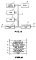
- the area map of the RAM 7 in Fig. 5 is shown in Fig. 6 and comprises a calling dial number register area a, an automatic calling dial number register area b, an automatic calling timer register area c, an automatic calling time register area d and an automatic calling timer area e.
- the function area of the clock 13 explained in connection with Figs. 1 and 5 may also be secured in the RAM 7 as shown by a block diagram in Fig. 7 to thereby realize on a software basis the calling request resulting from the timer 11 and comparator 14 and the function of the clock 13 in the foregoing embodiment, in which case the area map of the RAM 7 in Fig. 7 comprises, in addition to such areas a to e, a time counter area f for realizing the clock function, as shown in the memory map of Fig. 6 as shown in Fig. 8.
- the areas a to e are the same as those in Fig. 6 and thus explanation thereof is omitted.
Abstract
Description
- The present invention relates to car telephone equipments and, more particularly, to a car telephone equipment which can automatically call a destination party after passage of a specified time period or at a specified time, that is, which has an automatic calling function.
- In these years, car telephone equipments have spread in communication service fields.
- There has been suggested such a car telephone equipment that has a voice recognization function to allow the user of the equipment to easily achieve calling and speech operations even during his driving of a car, that is, that has a so-called voice dialling function of automatically calling a destination party in response to a voice utterance and eliminating the need for any key input dialling operation.
- With such a car telephone equipment having the voice dialling function, when it is desired for the user to call a predetermined destination party at a predetermined time, the user must drive his car while always getting worried about the predetermined time, which is highly dangeous and may often result undesirably in a car accident. In addition, when concentrating his attention on the car driving, the user is apt to forget to dial or call the predetermined destination party.
- In view of such circumstances, it is an object of the present invention to provide a car telephone equipment which can perform an automatic calling operation over a preset telephone number at a preset time or after passage of a preset time period.
- In accordance with the present invention, the above object is attained by providing a car telephone equipment which comprises means for inputting a telephone number, number storage means for storing the input telephone number, time control means for having a clock function or a timer function, specification means for specifying a predetermined telephone number previously stored in the number storage means and for specifiying a predetermined time or a predetermined time interval for the time control means, and means for calling a destination party corresponding to the predetermined telephone number specified by the specification means when a time or a time period at the time control means coincides with the predetermined time or the predetermined time period specified by the specification means.
- In the present invention, when a time or a time period at the time control means coincides with the predetermined time or the predetermined time period specified by the specification means, the calling means can reliably perform a calling operation over the predetermined telephone number specified by the specification means.
- In this way, the car telephone equipment of the present invention can positively call the destination party corresponding to the predetermined telephone number specified by the specification means through the calling means when a time or a time period at the time control means coincides with the predetermined time or the predetermined time period specified by the specification means. As a result, even if the user concentrates his attention on the car driving, the telephone equipment can automatically call the predetermined party at the predetermined or after passage of the predetermined time period. Thus, the user can keep his mind only on the driving and even when he forgets to call the party, the telephone equipment in place of him can call the destination party reliably and automatically.
- Fig. 1 is a block diagram showing an embodiment of a car telephone equipment having an automatic calling function in accordance with the present invention;
- Figs. 2 to 4 shows a flowchart for explaining the operation of the embodiment of Fig. 1;
- Fig. 5 is a block diagram showing a control circuit in another embodiment of the present invention;
- Fig. 6 is a memory map for explaining the areas of a RAM in Fig. 5;
- Fig. 7 is a block diagram showing a control circuit in yet a further embodiment of the present invention; and
- Fig. 8 is a memory map for explaining the areas of a RAM in Fig. 7.
- An embodiment of the present invention will be detailed with reference to the accompanying drawings.
- Referring first to Fig. 1, there is shown a block diagram of an embodiment of a car telephone equipment having an automatic calling function in accordance with the present invention. In the drawing, the car telephone equipment comprises an antenna 1, a transmitter/receiver unit 2, a
control circuit 3 and ahandset 4, which parts are mounted on a car (not shown). - The
handset 4 includes areceiver 401 and atransmitter 402 through which a voice signal is vocally input and output respectively, and akey pad 403 for key inputting operation. - The
control circuit 3 comprises amicrocomputer 5 for control of various parts and for input and output of various types of signals, a nonvolatile memory (ROM) 6 for storing therein a program for control of themicrocomputer 5 and the like, a volatile memory (RAM) 7 for storing therein various sorts of data, aninterface connector 8 which connects thecontrol circuit 3 to the transmitter/receiver unit 2, an input/output port 9 for the transmitter/receiver unit 2, asystem bus 10 which are connected between various parts, a timer 11 which has set information stored therein and which outputs an interrupt signal when the set time period has expired, aninterrupt line 12, aclock 13 for outputting a time data, a time register 14 for storing therein a time data that is received from thehandset 4 through key operation or voice input and that corresponds to a time at which the telephone equipment is to call, acomparator 15 which compares a time data generated at theclock 13 with a time data stored in thetime register 14 and outputs an interrupt signal when finding a coincidence therebetween, a dial-number memory 16 for storing the telephone number of a destination party which is received from thehandset 4 through key operation or voice input and with which the telephone equipment is to call the destination party, an input/output port 17 for thehandset 4, and aninterface connector 18 which connects thecontrol circuit 3 to thehandset 4. - Explanation will next be made as to the operation of the car telephone equipment of such an arragement as mentioned above when performing its automatic calling function. Assume in the following explanation that the specification of a calling time period and a calling time is effected on a vocal input basis and the input of a destination party telephone number is similarly vocally effected.
- First, when it is desired to automatically call a desired destination party after passage of a desired time, the operator of the telephone equipment picks up the
handset 4 to put the handset in its off-hook state and utters a desired calling time period and a desired destination party telephone number through thetransmitter 402 of thehandset 4 for the purpose of voice input. For example, when the operator speaks "30 minutes later" and then the desired destination party telephone number "xxx - xxx - xxxx", the information indicative of the off-hook state of thehandset 4, the voice information indicative of the desired time period and the voice information indicative of the party telephone number are input to themicrocomputer 5 through theinterface connector 18, the input/output port 17 and thesystem bus 10. Themicrocomputer 5, when receiving these information, carries out such processings as shown in Figs. 2 and 3 on the basis of the received information. - More in detail, when the
handset 4 is put in the off-hook state (step 301), themicrocomputer 5 checks the absence of presence of the specified time period as the next voice input (step 302). The presence of the second specified time voice input causes themicrocomputer 5 to recognize the second voice input (step 303). The voice input recognization by themicrocomputer 5 may be executed by a well known speech recognization technique, for example, by previously storing the voice pattern of the operator in the memory and by comparing the input voice pattern with the previously stored reference voice pattern to recognize the input voice. - When recognizing the specified voice input time period at the
step 303, themicrocomputer 5 sets the specified time period in the timer 11 (step 304). The microcomputer then judges whether or not an voice input on a destination party telephone number is present (step 305). The presence of the destination party telephone number voice input causes themicrocomputer 5 to recognize the voice-input party telephone number (step 306). The voice recogniation of the party telephone number may be carried out by the similar technique to that used in the foregoing voice recognization of the specified time period. - After having recognized the voice-input destination party telephone number at the
step 306, the microcomputer then stores the recognized destination party telephone number in the dial number memory 16 (step 307). - Subsequently, the
microcomputer 5 judges whether or not thehandset 4 is in its on-hook state (step 308). The judgement of the on-hook state causes themicrocomputer 5 to start the timer 11 (step 309). - After that, the
microcomputer 5 monitors whether or not the timer 11 has expired or timed out (step 310). The time-out of the timer 11 causes an automatic call request to be sent from the timer 11 through theinterrupt line 12 to themicrocomputer 5, so that themicrocomputer 5 turns on the transmitter of the transmitter/receiver unit 2 (step 311) to establish a radio circuit between the telephone equipment and a base station (not shown) (step 312), to transfer the contents of thedial number memory 16 indicative of the party telephone number to a calling telephone number memory zone in theRAM 7, and to transmit the destination party telephone number from the transmitter (step 313). And the telephone equipment, when receiving an answer signal from the party in response to the transmission of the party telephone number (step 314), is put in a speech mode (step 315). In this manner, when the user merely inputs a desired time period and a desired destination party telephone number to the telephone equipment through thetransmitter 402 of thehandset 4, the telephone equipment can automatically call the desired input party after passage of the desired time period. - Explanation will next be made as to the operation of the telephone equipment when calling a desired destination party at a desired time. To this end, the operator first causes the
handset 4 to go off-hook and speaks a desired time and a party telephone number for their voice input. For example, the operator utters "at two fourty" and then a destination party telephone number "xxx - xxx - xxxx". This results in that the information indicative of the off-hook state of thehandset 4, the voice information indicative of the desired time and the voice information indicative of the party telephone number are input to themicrocomputer 5 through theinterface connector 18, the input/output port 17 and thesystem bus 10. - The
microcomputer 5 detects that thehandset 4 has been put in the off-hook state (step 301). If not a specified time period but a specified time is vocally input (step 302), then themicrocomputer 5 detects it at astep 316 and then recognizes the voice-input specified time at astep 317. - The recognization of the voice-input specified time at the
step 317 causes themicrocomputer 5 to store the recognized specified-time in the time register 14 (step 318). - The microcomputer then judges whether or not the voice input on the party telephone number is present (step 319). When the
microcomputer 5 judges the presence of the party-telephone-number voice input, it recognizes the voice-input destination party telephone number (step 320). - After having recognized the voice-input party telephone number at the
step 320, themicrocomputer 5 then stores the recognized destination party telephone number in the dial number memory 16 (step 321). - After that, the
microcomputer 5 detects, on the basis of an output of thecomparator 15, whether or not the contents of theclock 13 coincides with the contents of the time register 14 (step 322). If themicrocomputer 5 detects the coincidence between the contents of theclock 13 and the contents of the time register 14 at thecomparator 15, then themicrocomputer 5 receives an automatic calling request from thecomparator 15 through theinterrupt line 12. As a result, themicrocomputer 5 turns on the transmitter of the transmitter/receiver unit 2 (step 311) to establish a radio communication circuit between the telephone equipment and a base station (not shown) (step 312), to transfer the contents of thedial number memory 16 indicative of the party telephone number to a calling telephone number memory zone in theRAM 7, and to transmit the party telephone number from the transmitter (step 313). And the telephone equipment, when receiving an answer signal from the party in response to the transmission of the destination party telephone number (step 314), is put in the speech mode (step 315). - In this way, in the present embodiment, the destination party telephone number and calling time period (after expiration of which, the calling is to be done by the telephone equipment) or the calling time are previously vocally input to the telephone equipment through the
handset 4 to previously store the telephone number in thedial number memory 16 and the time period in the timer 11 or the time in the time register 14, so that, when the timer 11 times out or when thecomparators 15 finds a coincidence between the time of theclock 13 and the time of the time register 14, themicrocomputer 5 can automatically call the destination party. As a result, even if the user or driver of the car carrying the telephone equipment concentrates on his car driving, he can reliably call the desired party at the predetermined time or after passage of the predetermined time interval and have a conversation with the party without being nervous about the calling time. - The foregoing embodiment has been arranged so that the operation of the telephone equipment is repeated until the equipment receives the specified time interval input or the specified time input at the
step step 319 or until the equipment receives the answer signal from the destination party at thestep 314. However, in practical applications, a time monitoring element is provided in each of these repetitive loops so that the expiration of a predetermined time enables the control to go out of these loops. - Further, although the destination party telephone number and the calling time period (after expiration of which, the calling is to be done by the telephone equipment) or the calling time are vocally input to the telephone equipment through the
receiver 402 of thehandset 4 in the foregoing embodiment, the destination party telephone number and the calling time period or the time may be input through the key operation of thekey pad 403 of thehandset 4. In this connection, the latter case can also be arranged in substantially the same manner as in the foregoing embodiment. - Furthermore, in the foregoing embodiment, the timer 11,
time register 14 anddial number memory 16 explained in connection with Fig. 1 may be secured in theRAM 7 as shown by a block diagram in Fig. 5 to thereby realize on a software basis the calling request resulting from the timer 11 andcomparator 14 in the foregoing embodiment. In this case, the area map of theRAM 7 in Fig. 5 is shown in Fig. 6 and comprises a calling dial number register area a, an automatic calling dial number register area b, an automatic calling timer register area c, an automatic calling time register area d and an automatic calling timer area e. - In each of the foregoing embodiments, the function area of the
clock 13 explained in connection with Figs. 1 and 5 may also be secured in theRAM 7 as shown by a block diagram in Fig. 7 to thereby realize on a software basis the calling request resulting from the timer 11 andcomparator 14 and the function of theclock 13 in the foregoing embodiment, in which case the area map of theRAM 7 in Fig. 7 comprises, in addition to such areas a to e, a time counter area f for realizing the clock function, as shown in the memory map of Fig. 6 as shown in Fig. 8. The areas a to e are the same as those in Fig. 6 and thus explanation thereof is omitted.
Claims (16)
means for inputting a telephone number of a destination party;
timer means;
means for setting a desired time period at said timer means;
means for detecting a time-out state of said timer means; and
automatic calling means for establishing said radio communication circuit between said base station and the equipment on the basis of a detection output of said detecting means and for performing an automatic calling operation over said destination party telephone number received from said input means.
means for inputting a telephone number of a destination party;
time generating means;
means for setting a desired time
means for detecting a coincidence between a time generated from said time generating means and a time set by said setting means; and
automatic calling means for establishing said radio communication circuit between said base station and said equipment on the basis of a detection output of said detecting means and for performing an automatic calling operation over said destination party telephone number received from said input means.
input means for inputting a telephone number;
number storage means for storing said received telephone number input by said input means;
time-period control means having a timer function;
specification means for specifying the predetermined telephone number stored in said number storage means and for specifying a predetermined time for the timer function of said time control means; and
calling means for performing a calling operation corresponding to the predetermined telephone number specified by said specification means when a time at said time-period control means coincides with said predetermined time specified by said specification means.
input means for inputting a telephone number;
number storage means for storing said received telephone number;
time-period control means having a clock function;
specification means for specifying the predetermined telephone number stored in said number storage means and for specifying a predetermined time period for the timer function of said time control means; and
calling means for performing a calling operation corresponding to the predetermined telephone number specified by said specification means when a time period at said time-period control means coincides with said predetermined time period specified by said specification means.
Applications Claiming Priority (2)
| Application Number | Priority Date | Filing Date | Title |
|---|---|---|---|
| JP62234432A JPS6477353A (en) | 1987-09-18 | 1987-09-18 | Land mobile telephone system |
| JP234432/87 | 1987-09-18 |
Publications (2)
| Publication Number | Publication Date |
|---|---|
| EP0308204A2 true EP0308204A2 (en) | 1989-03-22 |
| EP0308204A3 EP0308204A3 (en) | 1990-05-23 |
Family
ID=16970921
Family Applications (1)
| Application Number | Title | Priority Date | Filing Date |
|---|---|---|---|
| EP88308507A Ceased EP0308204A3 (en) | 1987-09-18 | 1988-09-14 | Car telephone equipment having automatic calling function |
Country Status (5)
| Country | Link |
|---|---|
| US (1) | US4939768A (en) |
| EP (1) | EP0308204A3 (en) |
| JP (1) | JPS6477353A (en) |
| KR (1) | KR910005473B1 (en) |
| CA (1) | CA1293300C (en) |
Cited By (10)
| Publication number | Priority date | Publication date | Assignee | Title |
|---|---|---|---|---|
| FR2654565A1 (en) * | 1989-11-15 | 1991-05-17 | Corneux Michel | DEVICE FOR HOURLY PROGRAMMING AND AUTOMATICALLY RETRIEVING CALLS OF A TELEPHONE LINE OF A SUBSCRIBER. |
| EP0554180A2 (en) * | 1992-01-30 | 1993-08-04 | Lg Electronics Inc. | Message sending method and apparatus |
| GB2306276A (en) * | 1995-10-11 | 1997-04-30 | Samsung Electronics Co Ltd | Automatic calling method for a mobile telephone |
| FR2746568A1 (en) * | 1996-03-25 | 1997-09-26 | Motorola Inc | PROCESS FOR ALLOWING A TELEPHONE TO REMIND THE USER THAT IT MUST MAKE A TELEPHONE COMMUNICATION AND TO AUTOMATICALLY DIAL THE CORRESPONDING NUMBER |
| WO1998005182A2 (en) * | 1996-07-31 | 1998-02-05 | Ericsson Inc. | Call generator within a mobile telecommunications network |
| EP0880241A2 (en) * | 1992-09-09 | 1998-11-25 | Hitachi, Ltd. | Mobile communications equipment |
| DE19927843A1 (en) * | 1999-05-10 | 2001-01-11 | E Lead Electronic Co | System for selecting from electronic telephone directory in vehicle has index and data units, temporary register, numeric code checker, selection device, controller, remote tone detection unit |
| EP1128640A2 (en) * | 2000-02-21 | 2001-08-29 | BECKER GmbH | Car telephone and method of operating the same |
| WO2007074433A2 (en) | 2005-12-29 | 2007-07-05 | Sandisk Il Ltd. | Phone batch calling task management system |
| CN113163052A (en) * | 2020-01-22 | 2021-07-23 | 华为技术有限公司 | Emergency call method and electronic equipment |
Families Citing this family (10)
| Publication number | Priority date | Publication date | Assignee | Title |
|---|---|---|---|---|
| JPH0354946A (en) * | 1989-07-24 | 1991-03-08 | Nec Corp | Automobile telephone system |
| JP2974709B2 (en) * | 1990-01-26 | 1999-11-10 | 株式会社東芝 | Wireless telephone device and wireless telephone control device |
| US5046082A (en) * | 1990-05-02 | 1991-09-03 | Gte Mobile Communications Service Corporation | Remote accessing system for cellular telephones |
| US5109403A (en) * | 1990-05-11 | 1992-04-28 | Goldstar Products Co., Limited | System for programming of features of a mobile cellular telephone unit |
| US5297183A (en) * | 1992-04-13 | 1994-03-22 | Vcs Industries, Inc. | Speech recognition system for electronic switches in a cellular telephone or personal communication network |
| US5596636A (en) * | 1995-04-21 | 1997-01-21 | Davies; Peter | Tee time scheduling device |
| CA2191805A1 (en) | 1995-12-15 | 1997-06-16 | Jason Paul Demont | Apparatus and method for transmitting a signal |
| KR19980057462A (en) * | 1996-12-30 | 1998-09-25 | 김광호 | How to redial in case of poor phone quality on your mobile phone |
| JP3123988B2 (en) * | 1998-09-28 | 2001-01-15 | 埼玉日本電気株式会社 | Mobile phone |
| US7421289B2 (en) * | 2001-02-21 | 2008-09-02 | Harman Becker Automotive Systems Gmbh | Motor vehicle telephone system |
Citations (4)
| Publication number | Priority date | Publication date | Assignee | Title |
|---|---|---|---|---|
| JPS5765052A (en) * | 1980-10-09 | 1982-04-20 | Nec Corp | Automatic all controller |
| DE3049049A1 (en) * | 1980-12-24 | 1982-07-01 | Licentia Patent-Verwaltungs-Gmbh, 6000 Frankfurt | Telephone subscriber automatic dialling unit - has electronic clock for dialling stored number at given time |
| FR2530103A1 (en) * | 1982-07-09 | 1984-01-13 | Thomson Csf Mat Tel | Appointment reminder device for electronic telephone terminal |
| DE3608497A1 (en) * | 1986-03-14 | 1987-09-17 | Standard Elektrik Lorenz Ag | Method and device for voice-controlled operation of a telecommunications terminal |
Family Cites Families (2)
| Publication number | Priority date | Publication date | Assignee | Title |
|---|---|---|---|---|
| US4481382A (en) * | 1982-09-29 | 1984-11-06 | Villa Real Antony Euclid C | Programmable telephone system |
| FR2571191B1 (en) * | 1984-10-02 | 1986-12-26 | Renault | RADIOTELEPHONE SYSTEM, PARTICULARLY FOR MOTOR VEHICLE |
-
1987
- 1987-09-18 JP JP62234432A patent/JPS6477353A/en active Pending
-
1988
- 1988-09-14 EP EP88308507A patent/EP0308204A3/en not_active Ceased
- 1988-09-15 KR KR8811980A patent/KR910005473B1/en not_active IP Right Cessation
- 1988-09-16 US US07/245,256 patent/US4939768A/en not_active Expired - Lifetime
- 1988-09-16 CA CA000577687A patent/CA1293300C/en not_active Expired - Lifetime
Patent Citations (4)
| Publication number | Priority date | Publication date | Assignee | Title |
|---|---|---|---|---|
| JPS5765052A (en) * | 1980-10-09 | 1982-04-20 | Nec Corp | Automatic all controller |
| DE3049049A1 (en) * | 1980-12-24 | 1982-07-01 | Licentia Patent-Verwaltungs-Gmbh, 6000 Frankfurt | Telephone subscriber automatic dialling unit - has electronic clock for dialling stored number at given time |
| FR2530103A1 (en) * | 1982-07-09 | 1984-01-13 | Thomson Csf Mat Tel | Appointment reminder device for electronic telephone terminal |
| DE3608497A1 (en) * | 1986-03-14 | 1987-09-17 | Standard Elektrik Lorenz Ag | Method and device for voice-controlled operation of a telecommunications terminal |
Non-Patent Citations (2)
| Title |
|---|
| PATENT ABSTRACTS OF JAPAN, vol. 10, no. 61 (E-367)[2118], 11th March 1986; JP-A-60 214 126 (TOYOTA) * |
| PATENT ABSTRACTS OF JAPAN, vol. 6, no. 140 (E-121)[1018], 29th July 1982; & JP-A-57 065 052 (NIPPON DENKI K.K.) * |
Cited By (23)
| Publication number | Priority date | Publication date | Assignee | Title |
|---|---|---|---|---|
| EP0428448A1 (en) * | 1989-11-15 | 1991-05-22 | ETAT FRANCAIS représenté par le C.N.E.T. | Device for time-programming and for automatic transfer of the calls of a telephone subscriber line |
| FR2654565A1 (en) * | 1989-11-15 | 1991-05-17 | Corneux Michel | DEVICE FOR HOURLY PROGRAMMING AND AUTOMATICALLY RETRIEVING CALLS OF A TELEPHONE LINE OF A SUBSCRIBER. |
| EP0554180A2 (en) * | 1992-01-30 | 1993-08-04 | Lg Electronics Inc. | Message sending method and apparatus |
| EP0554180A3 (en) * | 1992-01-30 | 1993-10-13 | Goldstar Co. Ltd. | Message sending method and apparatus |
| EP0880241A2 (en) * | 1992-09-09 | 1998-11-25 | Hitachi, Ltd. | Mobile communications equipment |
| EP0880241A3 (en) * | 1992-09-09 | 1999-04-07 | Hitachi, Ltd. | Mobile communications equipment |
| GB2306276A (en) * | 1995-10-11 | 1997-04-30 | Samsung Electronics Co Ltd | Automatic calling method for a mobile telephone |
| US5943626A (en) * | 1995-10-11 | 1999-08-24 | Samsung Electronics Co., Ltd. | Reserved communication technique in mobile telephone |
| ES2116932A1 (en) * | 1995-10-11 | 1998-07-16 | Samsung Electronics Co Ltd | Reserved communication technique in mobile telephone |
| FR2746568A1 (en) * | 1996-03-25 | 1997-09-26 | Motorola Inc | PROCESS FOR ALLOWING A TELEPHONE TO REMIND THE USER THAT IT MUST MAKE A TELEPHONE COMMUNICATION AND TO AUTOMATICALLY DIAL THE CORRESPONDING NUMBER |
| DE19710689C2 (en) * | 1996-03-25 | 2000-06-08 | Motorola Inc | Method for a telephone device for automatically establishing a telephone connection |
| US5819180A (en) * | 1996-07-31 | 1998-10-06 | Ericsson Inc. | Automatic call generator with a mobile telecommunications network based upon mobile subscriber's location |
| WO1998005182A3 (en) * | 1996-07-31 | 1998-04-16 | Ericsson Ge Mobile Inc | Call generator within a mobile telecommunications network |
| WO1998005182A2 (en) * | 1996-07-31 | 1998-02-05 | Ericsson Inc. | Call generator within a mobile telecommunications network |
| DE19927843A1 (en) * | 1999-05-10 | 2001-01-11 | E Lead Electronic Co | System for selecting from electronic telephone directory in vehicle has index and data units, temporary register, numeric code checker, selection device, controller, remote tone detection unit |
| DE19927843C2 (en) * | 1999-05-10 | 2001-04-19 | E Lead Electronic Co | System for dialing from an electronic phone book in combination with a hands-free mobile phone system for vehicles |
| EP1128640A2 (en) * | 2000-02-21 | 2001-08-29 | BECKER GmbH | Car telephone and method of operating the same |
| EP1128640A3 (en) * | 2000-02-21 | 2003-11-19 | BECKER GmbH | Car telephone and method of operating the same |
| WO2007074433A2 (en) | 2005-12-29 | 2007-07-05 | Sandisk Il Ltd. | Phone batch calling task management system |
| EP1974530A2 (en) * | 2005-12-29 | 2008-10-01 | Modu Ltd. | Phone batch calling task management system |
| EP1974530A4 (en) * | 2005-12-29 | 2010-06-30 | Modu Ltd | Phone batch calling task management system |
| CN113163052A (en) * | 2020-01-22 | 2021-07-23 | 华为技术有限公司 | Emergency call method and electronic equipment |
| CN113163052B (en) * | 2020-01-22 | 2023-03-10 | 华为技术有限公司 | Emergency call method and electronic equipment |
Also Published As
| Publication number | Publication date |
|---|---|
| JPS6477353A (en) | 1989-03-23 |
| KR890006046A (en) | 1989-05-18 |
| CA1293300C (en) | 1991-12-17 |
| KR910005473B1 (en) | 1991-07-29 |
| EP0308204A3 (en) | 1990-05-23 |
| US4939768A (en) | 1990-07-03 |
Similar Documents
| Publication | Publication Date | Title |
|---|---|---|
| EP0308204A2 (en) | Car telephone equipment having automatic calling function | |
| EP0880241B1 (en) | Mobile communications equipment | |
| KR950014293B1 (en) | Radio telephone apparatus | |
| EP0319210B1 (en) | Radio telephone apparatus | |
| CA1295064C (en) | Voice recognition system used in telephone apparatus | |
| EP0554093B1 (en) | Radio telecommunication apparatus | |
| US5950138A (en) | Hand-held telephone set | |
| US4450320A (en) | Dialing device with calling number and identification memory and method for using same | |
| US5799255A (en) | Method for controlling an accessory of a subscriber terminal equipment and an accessory of a subscriber terminal equipment | |
| EP0287061A2 (en) | Apparatus for controlling calls in a mobile communication system | |
| US20130137409A1 (en) | Systems and methods for mobile communications | |
| EP0366152A2 (en) | Cordless telephone | |
| EP0218450B1 (en) | Control system of a radio telephone apparatus | |
| HU224794B1 (en) | Process for operating a telecommunication terminal and telecommunication terminal | |
| US6253095B1 (en) | Telephone set, communications system, and method of setting security functions in telephone set | |
| US4885768A (en) | Active dipole telephone line protection device | |
| EP0717541B1 (en) | Cordless telephone system | |
| KR960020082A (en) | Method of providing location data of portable terminal | |
| KR100309417B1 (en) | Method for sending vehicle information of positioning system by using mobile | |
| JP2718365B2 (en) | Location registration method and authentication method | |
| JP2850798B2 (en) | Cordless telephone equipment | |
| JP2938059B1 (en) | In-vehicle calling device and calling method for mobile phone | |
| US7499697B2 (en) | Portable terminal device for diverting one-time only calls | |
| JP2838986B2 (en) | Cordless telephone equipment | |
| JPH08149195A (en) | Response detection-added dial system |
Legal Events
| Date | Code | Title | Description |
|---|---|---|---|
| PUAI | Public reference made under article 153(3) epc to a published international application that has entered the european phase |
Free format text: ORIGINAL CODE: 0009012 |
|
| 17P | Request for examination filed |
Effective date: 19880922 |
|
| AK | Designated contracting states |
Kind code of ref document: A2 Designated state(s): DE FR GB SE |
|
| PUAL | Search report despatched |
Free format text: ORIGINAL CODE: 0009013 |
|
| AK | Designated contracting states |
Kind code of ref document: A3 Designated state(s): DE FR GB SE |
|
| 17Q | First examination report despatched |
Effective date: 19920825 |
|
| APCB | Communication from the board of appeal sent |
Free format text: ORIGINAL CODE: EPIDOS OBAPE |
|
| APAB | Appeal dossier modified |
Free format text: ORIGINAL CODE: EPIDOS NOAPE |
|
| STAA | Information on the status of an ep patent application or granted ep patent |
Free format text: STATUS: THE APPLICATION HAS BEEN REFUSED |
|
| 18R | Application refused |
Effective date: 19960320 |
|
| APAF | Appeal reference modified |
Free format text: ORIGINAL CODE: EPIDOSCREFNE |