EP0308315B1 - Interpolation method - Google Patents
Interpolation method Download PDFInfo
- Publication number
- EP0308315B1 EP0308315B1 EP88402299A EP88402299A EP0308315B1 EP 0308315 B1 EP0308315 B1 EP 0308315B1 EP 88402299 A EP88402299 A EP 88402299A EP 88402299 A EP88402299 A EP 88402299A EP 0308315 B1 EP0308315 B1 EP 0308315B1
- Authority
- EP
- European Patent Office
- Prior art keywords
- image
- interpolation
- mesh
- memory
- coordinates
- Prior art date
- Legal status (The legal status is an assumption and is not a legal conclusion. Google has not performed a legal analysis and makes no representation as to the accuracy of the status listed.)
- Expired - Lifetime
Links
- 238000000034 method Methods 0.000 title claims description 29
- 230000015654 memory Effects 0.000 claims description 58
- 230000008569 process Effects 0.000 claims description 10
- 230000006870 function Effects 0.000 claims description 7
- 239000000203 mixture Substances 0.000 claims description 3
- 238000004020 luminiscence type Methods 0.000 claims 1
- 238000012937 correction Methods 0.000 description 33
- 238000006073 displacement reaction Methods 0.000 description 14
- 238000004364 calculation method Methods 0.000 description 12
- 239000002131 composite material Substances 0.000 description 9
- 239000011159 matrix material Substances 0.000 description 6
- 210000000056 organ Anatomy 0.000 description 6
- 238000012545 processing Methods 0.000 description 5
- 239000013078 crystal Substances 0.000 description 4
- 230000000694 effects Effects 0.000 description 4
- 238000007792 addition Methods 0.000 description 3
- 230000007547 defect Effects 0.000 description 3
- 238000009826 distribution Methods 0.000 description 3
- 230000002285 radioactive effect Effects 0.000 description 3
- 238000003860 storage Methods 0.000 description 3
- 230000008859 change Effects 0.000 description 2
- 238000001514 detection method Methods 0.000 description 2
- 238000005259 measurement Methods 0.000 description 2
- 238000009206 nuclear medicine Methods 0.000 description 2
- 238000003325 tomography Methods 0.000 description 2
- 230000007704 transition Effects 0.000 description 2
- 206010028980 Neoplasm Diseases 0.000 description 1
- 238000009825 accumulation Methods 0.000 description 1
- 230000032683 aging Effects 0.000 description 1
- 230000003321 amplification Effects 0.000 description 1
- 230000000747 cardiac effect Effects 0.000 description 1
- 238000010276 construction Methods 0.000 description 1
- 230000008602 contraction Effects 0.000 description 1
- 238000013016 damping Methods 0.000 description 1
- 230000007423 decrease Effects 0.000 description 1
- 238000013461 design Methods 0.000 description 1
- 238000011161 development Methods 0.000 description 1
- 230000018109 developmental process Effects 0.000 description 1
- 238000010586 diagram Methods 0.000 description 1
- 230000004069 differentiation Effects 0.000 description 1
- 230000005284 excitation Effects 0.000 description 1
- 238000002474 experimental method Methods 0.000 description 1
- 230000005251 gamma ray Effects 0.000 description 1
- 238000003702 image correction Methods 0.000 description 1
- 238000003384 imaging method Methods 0.000 description 1
- 230000006872 improvement Effects 0.000 description 1
- 230000003993 interaction Effects 0.000 description 1
- 238000012886 linear function Methods 0.000 description 1
- 238000004519 manufacturing process Methods 0.000 description 1
- 230000004048 modification Effects 0.000 description 1
- 238000012986 modification Methods 0.000 description 1
- 238000003199 nucleic acid amplification method Methods 0.000 description 1
- 230000008520 organization Effects 0.000 description 1
- 238000005293 physical law Methods 0.000 description 1
- 230000004044 response Effects 0.000 description 1
- 238000010200 validation analysis Methods 0.000 description 1
- 238000012800 visualization Methods 0.000 description 1
Images
Classifications
-
- G—PHYSICS
- G06—COMPUTING; CALCULATING OR COUNTING
- G06T—IMAGE DATA PROCESSING OR GENERATION, IN GENERAL
- G06T3/00—Geometric image transformation in the plane of the image
- G06T3/40—Scaling the whole image or part thereof
- G06T3/4007—Interpolation-based scaling, e.g. bilinear interpolation
-
- G06T5/80—
-
- A—HUMAN NECESSITIES
- A61—MEDICAL OR VETERINARY SCIENCE; HYGIENE
- A61B—DIAGNOSIS; SURGERY; IDENTIFICATION
- A61B6/00—Apparatus for radiation diagnosis, e.g. combined with radiation therapy equipment
- A61B6/42—Apparatus for radiation diagnosis, e.g. combined with radiation therapy equipment with arrangements for detecting radiation specially adapted for radiation diagnosis
- A61B6/4208—Apparatus for radiation diagnosis, e.g. combined with radiation therapy equipment with arrangements for detecting radiation specially adapted for radiation diagnosis characterised by using a particular type of detector
- A61B6/4258—Apparatus for radiation diagnosis, e.g. combined with radiation therapy equipment with arrangements for detecting radiation specially adapted for radiation diagnosis characterised by using a particular type of detector for detecting non x-ray radiation, e.g. gamma radiation
Definitions
- the present invention relates to a method of interpolating the value of a point in a mesh with N vertices.
- the interpolation studied is preferably of the bilinear type, although the invention applies to cases where it is neither linear nor even double but rather multiple.
- the mesh has four vertices, but in certain applications, in particular in imaging applications representing three-dimensional objects, the mesh could have a different number of vertices: for example three, six or eight vertices. .
- the interpolation method of the invention finds an application in the medical field where it can be used to correct distortions of images acquired with gamma cameras.
- the main interest of the interpolation method of the invention lies in the speed with which the interpolation can be done. This speed allows processing in real time while respecting the usual standards for video and television representation for viewing images.
- Gamma cameras are used in nuclear medicine to visualize in an organ the distribution of molecules marked by a radioactive isotope that has been injected into a patient.
- a gamma camera generally includes a collimator to focus the gamma-ray photons emitted by the patient, a scintillator crystal to transform gamma photons into light photons or scintillations, and a network of photo-multiplier tubes which transform each of the scintillations into electrical pulses called electrical contributions from tubes.
- They also include electronic circuits to produce from the electrical contributions provided by the photo-multiplier tubes, signals of coordinates X and Y of the place where a scintillation occurred, as well as a validation signal Z when the W energy of the scintillation belongs to a predetermined energy band.
- This detection chain is generally followed by a display assembly which may include a cathode oscilloscope controlled by the signals of coordinates X, Y, and by Z to visualize by a luminous point on the screen the point of impact of the gamma photon. on the crystal. This impact is also called an image event.
- the display assembly may optionally include a photographic device for forming an image of the organ observed by integrating a large number of light points produced on the cathode-ray screen. It can also include digital image processing.
- the display assembly can be adapted to the representation of tomographies of the organ observed. To achieve this goal, several images of this organ are acquired according to a plurality of observation orientations of the gamma-camera with respect to this organ. By signal processing, analogous to those encountered in CT scanners, images of sections of the organs examined can be reconstructed.
- a gamma camera must have a good spatial resolution, that is to say the ability to distinguish from small close-up radioactive sources, a good response in counting rate, that is to say the ability to process a large number of 'events per unit of time, and image quality as independent as possible from the energy of the isotope under consideration.
- the spatial resolution depends on the precision of the calculations of the X and Y coordinates of each of the image events. The quality of the development of these coordinates depends on the accuracy of the measurements and the physical laws governing the operation of the different parts of the gamma-camera.
- the interaction of a gamma photon with the crystal gives rise to a light scintillation, the intensity of which decreases expotentially over time.
- This scintillation is seen by several photo-multiplier tubes simultaneously.
- the light photons making up this scintillation pull photoelectrons from the photo-cathodes of the photo-multiplier tubes.
- the number of photo-electrons torn off obeys, for a given scintillation, the Poisson statistical law.
- the electrical contribution is a substantially Gaussian function of the distance separating the center of the photo-multiplier tube from the projection of the place where the scintillation occurred. If the scintillation occurs directly above the center of the tube, the electrical contribution is maximum. The further the scintillation site is from the center of the tube, the lower the electrical contribution. For example, if a scintillation occurs directly above the wall of the tube, the electrical contribution of the latter is approximately halved compared to the maximum electrical contribution.
- a scintillation is seen by several photo-multiplier tubes simultaneously, generally 6 to 10 tubes. Also, the determination of the location of this scintillation on the crystal, itself representative of the place of emission of the excitation gamma photon (and therefore of the image event), can be obtained by calculating the location of the barycenter of the electrical contributions delivered by all the photo-multiplier tubes excited by this scintillation. This calculation is carried out simply, according to the American patent ANGER No. 3011057, by injecting the electrical contributions through a set of resistance matrices whose resistance values are a function of the positions of the photo-multiplier tubes to which they are connected.
- each matrix there are as many resistors as there are photo-multiplier tubes in the network of tubes.
- Each of the resistors is connected on the one hand to the output of a different photo-multiplier tube and on the other hand to a common point which constitutes the output of the matrix.
- One of the problems presented by the ANGER type gamma cameras is that they present geometric distortions of the image linked to the light capture structure: scintillator crystal-photomultiplier tube-barycentration matrix.
- a computer develops a correction matrix of 64 X 64 new U and V coordinates of an undistorted image corresponding to the same number of X and Y coordinates of l distorted image of the target.
- the acquired X and Y coordinates of the image events are coded on 12 bits.
- the 6 most significant bits of X and Y address the memory of U and V.
- a linear interpolation is carried out using the 6 least significant bits of X and Y.
- Given an image field of approximately 400 mm diameter, a 12-bit coding of the coordinates of the image events should normally lead to an image definition of the order of 0.1 mm.
- the acquired coordinates of the image events are given on 12 bits, there remain 5 bits to make an interpolation of the true position of an image event in the mesh corrected to which we just determined it must belong.
- a first correction CI is calculated from the coordinates x (or respectively y) and corrections of coordinates of the two vertices of the mesh: DXa (or DYa) and DXb (or DYb).
- DXa or DYa
- DXb or DYb
- Another computation CJ is then calculated by interpolation between the other two vertices C and D of the mesh.
- CJx or CJy
- the final computation consists, starting from CI and CJ to obtain displacement DX (or DY).
- any image correction method based ultimately on such a direct addressing technique requires exorbitant memory capacity.
- a memory of 16 Mega words of 24 bits (12 bits to determine X corrected, and 12 bits to determine Y corrected) would be required. This memory would be addressed by the X and Y acquired and coded each on 12 bits. This capacity exceeds the technological limits currently available.
- a patent application GB-A-2 026 811 describes a method and a machine for reproducing a color image, a light brush scanning the original image.
- the analog image signal thus obtained is separated into n elementary image signals which are then digitalized, one of these signals is then stored, in its entirety, in a memory, while the others are sampled according to regular models, the sampled values being stored in memory.
- the elementary image signals with digital output are obtained in said memory, by reading the first elementary image signal without modification, by reading the others and by performing an interpolation of the stored values.
- the output signals are then used to obtain the desired reproduced image.
- the interpolation is carried out according to the method defined by the preamble of claim 1.
- the object of the invention is to remedy the drawbacks defined above by proposing an interpolation method where the memory capacity is not particularly increased but where on the other hand the interpolation calculation can be done in real time.
- the fact that the interpolation calculation can be done in real time can be used in the video domain. Indeed the representation of movements requires the acquisition and storage of many images. In order not to increase the memory capacities too much At the time of this storage, it may be useful, since we are only interested in movement, to store only degraded definition images. In some cases, in particular in the study of cardiac movements by gamma-camera, the images obtained have a weak definition from the start.
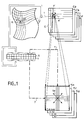
- FIG. 1 schematically represents an interpolation method similar to that used according to the invention.
- a point P or image event, is defined, after an acquisition, by its X and Y coordinates.
- the acquisition is an acquisition obtained following an experiment with a gamma-camera and, to fix ideas, the X and Y coordinates are given in binary form with 12 bits of definition.
- the point P belongs to a distorted image ID which is unusable. To be able to be used, this image must be corrected by an image distortion correction method. Ultimately, it is necessary to calculate the coordinates of a point P 'in a corrected image IC.
- each elementary cell M of the distorted image ID acquired is assigned a corrected cell M ′ whose vertices A, B, C and D are defined by corrections of coordinates, also called here weighting coefficients, DXa - DYa, DXb ... DYd.
- a first step consists in assigning to a mesh M a mesh M '.
- the second step consists in interpolating the position of the point P 'in the mesh M' according to the position of the point P in the mesh M and according to the weighting coefficients of the vertices of the mesh.
- the arrow 1 represents the first operation.
- the most significant bits of the X and Y coordinates are used. In a particular embodiment, the seven most significant bits are used so as to define a mesh of 128 X 128 meshes in the distorted images ID and corrected IC.
- the fineness of interpolation to be obtained is determined.
- the fineness of interpolation to be obtained relates to the five least significant bits, denoted x and y, of the coordinates X and Y.
- Ka is called the contribution (1-x-y + xy)
- Kd the contribution (xy) the invention aims to precalculate the contributions of Ka, Kb, Kc, and Kd, for all the possible values of x and y corresponding to the fineness of interpolation to be obtained. These values are then stored in read only memories called interpolation matrices.
- each x or y coordinate can therefore take 32 values.
- each memory cell has a contribution coded on eight bits.
- the interpolation requires a memory increase of 4 K bytes to store all the relative contributions.
- the correction mesh comprises eight memory zones known as of correction of coordinates and relating to the displacements of the tops of the meshes: DXa, DYa, DXb, ... DYd, of the fact that these corrections of coordinates are coded each on 11 bits (one sign bit, eight significant bits and two fractional bits), and the fact that the correction mesh is relative to a 128 X 128 resolution
- the overall memory size is 2 times 16 K words of 11 bits of RAM , and 4K bytes of ROM.
- the coordinate corrections must be able to change, as a function of the aging of the gamma-camera for example, while the precomputed relative contributions are immutable. They can therefore be stored in a read-only memory.
- the additional memory size for the interpolation matrices is therefore negligible.
- the precalculation of the interpolation contributions can be simplified by using, for programming the memories Ka, Kb and Kc, the results obtained for the precalculation of the memory Kd.
- the multiplication x.y has not been redone.
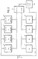
- FIG. 2 represents the preferred method of determining the corrected coordinates of the points P ′ in the mesh M ′.
- a bus 2 routes the X and Y coordinates to the coordinate correction memories 3 to 6 on the one hand, and to the interpolation memories 7 to 10 on the other hand.
- a multiplier-accumulator 15 connected to the outputs of these memories then receives correction memories, the correction of coordinates DX (or DY) on the one hand, and interpolation memories 7 to 10 the relative contributions of interpolation K of somewhere else. It performs the corresponding multiplications and the accumulation of results of these multiplications.
- IL delivers, as appropriate, the displacement DX then the displacement DY. With the accumulator multiplier 15 the processing is carried out in series.
- a correction circuit 150 then delivers the corrected coordinates of the image events by adding the calculated displacements to the distorted coordinates.
- the method of the invention can also make it possible to save more time.
- the addressing of the coordinate corrections of the different vertices of the correction mesh M ′ can be simultaneous.
- X and Y, or at least the 7 most significant bits of X and Y represent the top A of the mesh.
- the vertices B, C and D are deduced therefrom by an addition or a subtraction of a unit of least significant bit among the most significant bits. Consequently, we can have access simultaneously to the 8 weighting coefficients DXa, DYa, etc. At the same time, it is also possible to access the Ka, Kb, Kc and Kd contributions simultaneously.
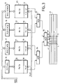
- the video application shown in part in Figure 3 is similar.
- this one a frame of an image available at low resolution.
- it has 64 rows and 64 columns: there are 4 K possible positions for image events and in one example each image element can be coded on 8 bits, ie 256 levels of gray, luminance or chrominance.
- the storage of images is therefore not very demanding.
- the x coordinate coded on 2 bits must be able to be worth from 1 to 4 and the y coordinate also coded on 2 bits must be able to also take the values from 1 to 4. Knowing the gray level, the weighting coefficient, Ca, Cb, Cc and Cd in each of the vertices A, B, C and D of the mesh, it is possible, by a calculation similar to that presented above, to calculate the intermediate gray levels of the intermediate points contained in the mesh.
- low definition source images are read at each cycle time to determine the gray levels, or weighting coefficients, Ca to Cd of the four vertices A to D of a mesh.
- the source memory can be quadrupled so as to be addressed simultaneously in X and Y in order to simultaneously deliver the weighting coefficients Ca to Cd.
- it can be organized differently by separating the even image events in x and y. This different organization then makes it possible to read simultaneously, but in different areas of this memory, the weighting coefficients Ca to Cd of the four vertices of the mesh. If necessary, a multiplexing of reading of this memory can also be organized.
- the memory of the source image or to simplify the explanation the source memories 16 to 19, then deliver the four weighting coefficients on 8 bits each representative of the gray level of one of the vertices of the mesh.
- These gray levels can be used as the address input of each of the memories 20 to 23 of composite precalculation having produced the product KC, and receiving as other address codes corresponding successively to each of the four intermediate positions of the interpolated points 41 to 44 located on the same line in the stitch.
- a line y is fixed, only x varies (from 1 to 4).
- the composite memories 20 to 23 then each deliver successively four results corresponding to the calculation of the luminosity weighted in four places in the mesh according to one of the vertices of this mesh.
- a set of adders 24 to 26 makes it possible to add the results delivered by the four memories 20 to 23 and to deliver the weighted brightness corresponding to this point.
- the four luminosities can be interpolated in 664 nomoseconds.
- the brightnesses in 256 points of a video line can therefore be calculated in 43 microseconds.
- the visualization of the image can then be obtained in conventional video mode. Indeed, in conventional video playback at 25 frames per second, reading a line of an image lasts 64 microseconds.
- the compatibility of these two durations (64 microseconds being greater than 43 microseconds) qualifies the interpolation method thus presented for viewing "on the fly" from weakly defined images to highly defined images.
- the interpolation mode recommended in these two applications is preferably a linear mode. Given the fact that we are trying to represent two-dimensional images, the interpolation mode will even be bilinear. However, the invention can be transposed to an interpolation of a point in a three-dimensional geometric space, or even in a theoretical M-dimensional space. Furthermore, the interpolation is not necessarily of the linear type. Other functions than the linear function are also possible. Being a mesh with N vertices, it may only be necessary that the sum of the contributions relating to each of these vertices is equal to 1.
- N is equal to four as what has just been described.
- the number of vertices can be different. In these latter cases, rather than calculating the contributions according to a Cartesian definition, it may be preferable to use a polar definition.
Description
La présente invention à pour objet un procédé d'interpolation de la valeur d'un point dans une maille à N sommets. L'interpolation étudiée est de préférence de type bilinéaire encore que l'invention s'applique à des cas où elle ne serait ni linéaire ni même double mais plutôt multiple. Dans l'exemple décrit la maille comporte quatre sommets mais dans certaines applications, en particulier dans des applications d'imagerie en représentation d'objets à trois dimensions, la maille pourrait comporter un nombre différent de sommets : par exemple trois, six ou huit sommets. Le procédé d'interpolation de l'invention trouve une application dans le domaine médical où il peut être utilisé pour corriger des distorsions d'images acquises avec les gamma-caméras. Il peut aussi être utilisé dans le domaine vidéo où il permet de représenter des images de faible définition, par exemple à 64 X 64 éléments d'image, comme des images haute définition, par exemple à 256 X 256 éléments d'image. Le principal intérêt du procédé d'interpolation de l'invention réside dans la rapidité avec laquelle l'interpolation peut être faite. Cette rapidité autorise le traitement en temps réel en respectant pour visualiser les images les normes habituelles de représentation vidéo télévision.The present invention relates to a method of interpolating the value of a point in a mesh with N vertices. The interpolation studied is preferably of the bilinear type, although the invention applies to cases where it is neither linear nor even double but rather multiple. In the example described, the mesh has four vertices, but in certain applications, in particular in imaging applications representing three-dimensional objects, the mesh could have a different number of vertices: for example three, six or eight vertices. . The interpolation method of the invention finds an application in the medical field where it can be used to correct distortions of images acquired with gamma cameras. It can also be used in the video field where it makes it possible to represent images of low definition, for example with 64 X 64 picture elements, like high definition images, for example with 256 X 256 picture elements. The main interest of the interpolation method of the invention lies in the speed with which the interpolation can be done. This speed allows processing in real time while respecting the usual standards for video and television representation for viewing images.
Les gamma-caméras sont utilisées en médecine nucléaire pour visualiser dans un organe la répartition de molécules marquées par un isotope radioactif que l'on a injecté à un patient. Une gamma-caméra comprend généralement un collimateur pour focaliser les photons gammas émis par le patient, un cristal scintillateur pour transformer les photons gamma en photons lumineux ou scintillations, et un réseau de tubes photo-multiplicateurs qui transforment chacune des scintillations en des impulsions éléctriques dites contributions électriques de tubes. Elles comportent en outre des circuits électroniques pour produire à partir des contributions électriques fournies par les tubes photo-multiplicateurs, des signaux de coordonnées X et Y du lieu où s'est produite une scintillation, ainsi qu'un signal de validation Z quand l'énergie W de la scintillation appartient à une bande d'énergie prédéterminée.Gamma cameras are used in nuclear medicine to visualize in an organ the distribution of molecules marked by a radioactive isotope that has been injected into a patient. A gamma camera generally includes a collimator to focus the gamma-ray photons emitted by the patient, a scintillator crystal to transform gamma photons into light photons or scintillations, and a network of photo-multiplier tubes which transform each of the scintillations into electrical pulses called electrical contributions from tubes. They also include electronic circuits to produce from the electrical contributions provided by the photo-multiplier tubes, signals of coordinates X and Y of the place where a scintillation occurred, as well as a validation signal Z when the W energy of the scintillation belongs to a predetermined energy band.
Cette chaîne de détection est généralement suivie d'un ensemble de visualisation qui peut comporter un oscilloscope cathodique commandé par les signaux de coordonnés X, Y, et par Z pour visualiser par un point lumineux sur l'écran le point d'impact du photon gamma sur le cristal. Cet impact est aussi appelé évènement d'image. L'ensemble de visualisation peut éventuellement comporter un dispositif photographique pour former une image de l'organe observé en intégrant un grand nombre de points lumineux produits sur l'écran cathodique. Il peut par ailleurs comprendre un traitement numérique des images. En particulier l'ensemble de visualisation peut être adapté à la représentation de tomographies de l'organe observé. Pour atteindre ce but on acquiert plusieurs images de cet organe selon une pluralité d'orientations d'observation de la gamma-caméra par rapport à cet organe. Par des traitements du signal, analogues à ceux rencontrés dans les tomodensitomètres, on peut reconstituer des images de coupes des organes examinés.This detection chain is generally followed by a display assembly which may include a cathode oscilloscope controlled by the signals of coordinates X, Y, and by Z to visualize by a luminous point on the screen the point of impact of the gamma photon. on the crystal. This impact is also called an image event. The display assembly may optionally include a photographic device for forming an image of the organ observed by integrating a large number of light points produced on the cathode-ray screen. It can also include digital image processing. In particular, the display assembly can be adapted to the representation of tomographies of the organ observed. To achieve this goal, several images of this organ are acquired according to a plurality of observation orientations of the gamma-camera with respect to this organ. By signal processing, analogous to those encountered in CT scanners, images of sections of the organs examined can be reconstructed.
En autres qualités une gamma-caméra doit posséder une bonne résolution spatiale, c'est à dire la capacité de distinguer des petites sources radioactives rapprochées, une bonne réponse en taux de comptage, c'est à dire la capacité de traiter un grand nombre d'évènements par unité de temps, et une qualité d'image le plus possible indépendante de l'énergie de l'isotope considéré. La résolution spatiale dépend de la précision des calculs des coordonnées X et Y de chacun des évènements d'image. La qualité de l'élaboration de ces coordonnées dépend de la précision des mesures et des lois physiques régissant le fonctionnement des différentes parties de la gamma-caméra. Ainsi l'interaction d'un photon gamma avec le cristal donne naissance à une scintillation lumineuse dont l'intensité décroît expotentiellement avec le temps. Cette scintillation est vue par plusieurs tubes photo-multiplicateurs simultanément. Les photons lumineux composant cette scintillation arrachent des photo-électrons aux photo-cathodes des tubes photo-multiplicateurs. Le nombre des photo-électrons arrachés obéit, pour une scintillation donnée, à la loi statistique de Poisson. Par ailleurs, à énergie constante, la contribution électrique est une fonction sensiblement gaussienne de la distance séparant le centre du tube photo-multiplicateur de la projection du lieu où s'est produite la scintillation. Si la scintillation se produit à l'aplomb du centre du tube, la contribution électrique est maximum. Plus le lieu de la scintillation est éloigné du centre du tube plus la contribution électrique est faible. A titre d'exemple, si une scintillation se produit à l'aplomb de la paroi du tube la contribution électrique de celui-ci est environ réduite de moitié par rapport à la contribution électrique maximum.In other qualities, a gamma camera must have a good spatial resolution, that is to say the ability to distinguish from small close-up radioactive sources, a good response in counting rate, that is to say the ability to process a large number of 'events per unit of time, and image quality as independent as possible from the energy of the isotope under consideration. The spatial resolution depends on the precision of the calculations of the X and Y coordinates of each of the image events. The quality of the development of these coordinates depends on the accuracy of the measurements and the physical laws governing the operation of the different parts of the gamma-camera. Thus the interaction of a gamma photon with the crystal gives rise to a light scintillation, the intensity of which decreases expotentially over time. This scintillation is seen by several photo-multiplier tubes simultaneously. The light photons making up this scintillation pull photoelectrons from the photo-cathodes of the photo-multiplier tubes. The number of photo-electrons torn off obeys, for a given scintillation, the Poisson statistical law. Furthermore, at constant energy, the electrical contribution is a substantially Gaussian function of the distance separating the center of the photo-multiplier tube from the projection of the place where the scintillation occurred. If the scintillation occurs directly above the center of the tube, the electrical contribution is maximum. The further the scintillation site is from the center of the tube, the lower the electrical contribution. For example, if a scintillation occurs directly above the wall of the tube, the electrical contribution of the latter is approximately halved compared to the maximum electrical contribution.
Une scintillation est vue par plusieurs tubes photo-multiplicateurs simultanément, généralement 6 à 10 tubes. Aussi, la détermination de l'emplacement de cette scintillation sur le cristal, elle-même représentative du lieu d'émission du photon gamma d'excitation (et donc de l'évènement d'image), peut être obtenue en calculant l'emplacement du barycentre des contributions électriques délivrés par l'ensemble des tubes photo-multiplicateurs excités par cette scintillation. Ce calcul s'effectue simplement, selon le brevet américain ANGER N°3011057, en injectant les contributions éléctriques au travers d'un jeu de matrices de résistances dont les valeurs des résistances sont fonction des positions des tubes photo-multiplicateurs auxquels elles sont raccordées. Les positions de ces tubes sont repérées par rapport à des axes cartésiens de référence dont le point d'intersection est généralement situé au centre du réseau de tubes. Dans chaque matrice il y a autant de résistances qu'il y a de tubes photo-multiplicateurs dans le réseau de tubes. Chacune des résistances est reliée d'une part à la sortie d'un tube photo-multiplicateur différent et d'autre part à un point commun qui constitue la sortie de la matrice. Ces résistances effectuent ainsi une pondération des contributions électriques de chacun des tubes de photomultiplicateurs qui les alimentent.A scintillation is seen by several photo-multiplier tubes simultaneously, generally 6 to 10 tubes. Also, the determination of the location of this scintillation on the crystal, itself representative of the place of emission of the excitation gamma photon (and therefore of the image event), can be obtained by calculating the location of the barycenter of the electrical contributions delivered by all the photo-multiplier tubes excited by this scintillation. This calculation is carried out simply, according to the American patent ANGER No. 3011057, by injecting the electrical contributions through a set of resistance matrices whose resistance values are a function of the positions of the photo-multiplier tubes to which they are connected. The positions of these tubes are identified with respect to reference Cartesian axes, the point of intersection of which is generally located at the center of the network of tubes. In each matrix there are as many resistors as there are photo-multiplier tubes in the network of tubes. Each of the resistors is connected on the one hand to the output of a different photo-multiplier tube and on the other hand to a common point which constitutes the output of the matrix. These resistors thus carry out a weighting of the electrical contributions of each of the photomultiplier tubes which supply them.
Un des problèmes présentés par les gamma-caméra du type ANGER est qu'elles présentent des distorsions géométriques de l'image liées à la structure de captation de la lumière : cristal scintillateur-tube photomultiplicateur-matrice de barycentration.One of the problems presented by the ANGER type gamma cameras is that they present geometric distortions of the image linked to the light capture structure: scintillator crystal-photomultiplier tube-barycentration matrix.
Les progrès de la médecine nucléaire, et en particulier les améliorations faites pour recueillir davantage d'informations, et des informations meilleures, à partir des gamma-caméras, par exemple pour la détection de petites tumeurs, conduisent à optimiser la résolution spatiale au détriment de la linéarité caractéristique inhérente à la conception et à la réalisation des caméras. Il en résulte une distorsion spatiale gênante des images. Ces distorsions sont à l'origine de défauts d'uniformité de densité qui peuvent être importants. A titre d'exemple, une contraction de 0,4 mm du rayon de l'image d'une surface circulaire d'un centimètre de rayon conduit à un défaut d'uniformité de 8 %. Ces défauts d'uniformité peuvent être particulièrement gênants en tomographie où l'effet d'amplification des défauts d'uniformité dûs aux procédés de reconstruction peut être supérieur à un facteur 10.Advances in nuclear medicine, and in particular improvements made to collect more and better information from gamma cameras, for example for the detection of small tumors, lead to optimizing spatial resolution at the expense of the characteristic linearity inherent in the design and construction of the cameras. This results in an annoying spatial distortion of the images. These distortions are the source of density uniformity defects which can be significant. For example, a contraction of 0.4 mm in the image radius from a circular surface of one centimeter radius leads to a lack of uniformity of 8%. These uniformity defects can be particularly troublesome in tomography where the amplification effect of the uniformity defects due to the reconstruction processes can be greater than a factor of 10.
Dans l'état de la technique on a tenté de corriger les effets de cette distorsion. Le principe général de la correction est le suivant. On effectue la mesure d'une image d'une mire régulière placée entre une source radioactive d'émission uniforme et la gamma-caméra. Si la gamma-caméra était parfaite, l'image représentée devrait correspondre à la répartition régulière des trous ou des fentes de la mire. La mesure effectuée montre en fait des irrégularités provenant des effets de distorsion spatiales. On peut cependant utiliser dans l'image ainsi acquise la connaissance de la distorsion, mesurée en comparant l'image acquise à la répartition théorique à laquelle on aurait dû aboutir, pour effectuer les corrections des images ultérieurement acquises avec la même gamma-caméra.In the state of the art, attempts have been made to correct the effects of this distortion. The general principle of the correction is as follows. An image of a regular pattern placed between a radioactive source of uniform emission and the gamma camera is measured. If the gamma-camera was perfect, the image represented should correspond to the regular distribution of the holes or slits of the target. The measurement actually shows irregularities from the effects of spatial distortion. It is however possible to use in the image thus acquired the knowledge of the distortion, measured by comparing the acquired image with the theoretical distribution to which one should have arrived, to effect the corrections of the images subsequently acquired with the same gamma-camera.
Dans un état de la technique, constitué par le brevet européen N° 0021.366, un calculateur élabore une matrice de correction de 64 X 64 nouvelles coordonnées U et V d'une image non distordue correspondant à un même nombre de coordonnées X et Y de l'image distordue de la mire. En fonctionnement de correction, les coordonnées acquises X et Y des évènements d'images sont codées sur 12 bits. Les 6 bits de poids fort de X et Y adressent la mémoire des U et V. Puis une interpolation linéaire est effectuée en utilisant les 6 bits de poids faible de X et Y. On utilise ainsi le décalage d'un évènement d'image à placer par rapport aux quatre angles de la maille élémentaire U, V, de l'image corrigée dans laquelle l'élément d'image doit finalement se trouver. Compte tenu d'un champ image d'environ 400 mm de diamètre, une codification sur 12 bits des coordonnées des évènements d'image devrait normalement conduire à une définition d'image de l'ordre de 0,1 mm.In a state of the art, constituted by European patent N ° 0021.366, a computer develops a correction matrix of 64 X 64 new U and V coordinates of an undistorted image corresponding to the same number of X and Y coordinates of l distorted image of the target. In correction operation, the acquired X and Y coordinates of the image events are coded on 12 bits. The 6 most significant bits of X and Y address the memory of U and V. Then a linear interpolation is carried out using the 6 least significant bits of X and Y. We thus use the shift of an image event to place with respect to the four angles of the elementary mesh U, V, of the corrected image in which the image element must ultimately be found. Given an image field of approximately 400 mm diameter, a 12-bit coding of the coordinates of the image events should normally lead to an image definition of the order of 0.1 mm.
On a pu montrer que cette définition ne pouvait être obtenue réellement que si la matrice de correction était en fait une matrice de 128 X 128 mailles et si donc on utilisait 7 bits de poids fort pour déterminer dans quelle maille de l'image corrigée doit se trouver l'évènement d'image à placer. Cette détermination est équivalente à attribuer des corrections de coordonnées aux sommets des 128 X 128 mailles de l'image acquise. Ceci étant, cette différence n'influe pas dans le principe de la présente invention. En effet la réprésentation des images avec 128 X 128 évènements d'image est aussi trop grossière. Il est nécessaire d'atteindre une résolution plus fine. Compte tenu du fait que les coordonnées acquises des évènements d'image (de l'image distordue) sont données sur 12 bits, il reste 5 bits pour faire une interpolation de la position vraie d'un évènement d'image dans la maille corrigée à laquelle on vient de déterminer qu'il doit appartenir. On calcule par interpolation le déplacement à appliquer à l'évènement, à partir des corrections de coordonnées à appliquer aux sommets des mailles. Si on appelle x et y les coordonnées, relatives aux bits de poids faible, de l'élément d'image dans la maille acquise, l'interpolation consiste à déterminer DX DY les déplacements à appliquer à la position de l'évènement situé à l'intérieur d'une maille afin de la corriger. Cette correction dépend de x et de y et de la manière dont la maille acquise a été transformée pour devenir la maille corrigée. Si on appelle A,B, C, et D, les sommets d'une maille carrée dans l'image acquise, ces sommets avec la correction de distorsion doivent respectivement être transformés c'est à dire subir des corrections de coordonnées DXa-DYa, DXb-DYb, DXc-DYc et DXd-DYd selon les deux axes de référence de l'image. Ces corrections de coordonnées sont stockées dans une mémoire dite de correction.One could show that this definition could be obtained really only if the correction matrix was in fact a matrix of 128 X 128 meshes and if therefore one used 7 most significant bits to determine in which mesh of the corrected image must be find the image event to place. This determination is equivalent to assigning corrections of coordinates to the vertices of the 128 X 128 meshes of the acquired image. However, this difference does not affect the principle of the present invention. In fact, the representation of images with 128 X 128 image events is also too rough. It is necessary to reach a finer resolution. Taking into account that the acquired coordinates of the image events (of the distorted image) are given on 12 bits, there remain 5 bits to make an interpolation of the true position of an image event in the mesh corrected to which we just determined it must belong. One calculates by interpolation the displacement to be applied to the event, starting from the corrections of coordinates to be applied to the tops of the meshes. If one calls x and y the coordinates, relative to the least significant bits, of the image element in the acquired mesh, the interpolation consists in determining DX DY the displacements to be applied to the position of the event located at l inside a mesh to correct it. This correction depends on x and y and on the way in which the acquired mesh was transformed to become the corrected mesh. If we call A, B, C, and D, the vertices of a square mesh in the acquired image, these vertices with the distortion correction must respectively be transformed, that is to say undergo corrections of coordinates DXa-DYa, DXb-DYb, DXc-DYc and DXd-DYd along the two reference axes of the image. These coordinate corrections are stored in a so-called correction memory.
La correction de distorsion de la position de l'évènement d'image à replacer est alors donnée par les formules suivantes :
![]()
![]()
En fait la méthode classique de calcul d'interpolation passe, pour le calcul de chaque déplacement DX ou DY, par deux niveaux de calculs intermédiaires. On calcule d'abord une première correction CI à partir des coordonnées x (ou respectivement y) et des corrections de coordonnées des deux sommets de la maille : DXa (ou DYa) et DXb (ou DYb). Avec deux accès à la mémoire où sont enregistrées les coordonnées des sommets des mailles corrigées on obtient ainsi un résultat intermédiaire CIx (ou CIy). On calcule ensuite une autre correction CJ par interpolation entre les deux autres sommets C et D de la maille. On obtient de la même façon CJx (ou CJy) avec deux autres accès à la mémoire. Le calcul final consiste, à partir de CI et de CJ à obtenir le déplacement DX (ou DY). On a donc, pour obtenir chacun des déplacements d'image d'un l'évènement d'image dans l'image corrigée, procédé à quatre accès mémoire (en A, B, C et D), à quatre multiplications en tenant compte des coordonnées x (ou y), à deux additions pour déterminer CI et CJ, à deux accès aux valeurs intermédiaires CI et CJ, à deux autres multiplications en tenant compte des coordonnées y cette fois (ou x) et enfin à une addition pour obtenir le déplacement final DX (ou DY). Ces nombreuses opérations nuisent à la rapidité de la présentation des images corrigées.The correction of distortion of the position of the image event to be replaced is then given by the following formulas:
![]()
![]()
In fact the traditional method of calculation of interpolation passes, for the calculation of each displacement DX or DY, by two levels of intermediate calculations. First of all, a first correction CI is calculated from the coordinates x (or respectively y) and corrections of coordinates of the two vertices of the mesh: DXa (or DYa) and DXb (or DYb). With two accesses to the memory where the coordinates of the vertices of the corrected meshes are recorded, an intermediate result CIx (or CIy) is thus obtained. Another computation CJ is then calculated by interpolation between the other two vertices C and D of the mesh. CJx (or CJy) is obtained in the same way with two other accesses to the memory. The final computation consists, starting from CI and CJ to obtain displacement DX (or DY). To obtain each of the image displacements of an image event in the corrected image, therefore, we have four memory accesses (in A, B, C and D), four multiplications taking into account the x (or y) coordinates, two additions to determine CI and CJ, two accesses to the intermediate values CI and CJ, two other multiplications taking into account the y coordinates this time (or x) and finally to an addition to obtain the final displacement DX (or DY). These numerous operations affect the speed of the presentation of the corrected images.
Lorsque le nombre de bits de poids faible à interpoler est peu important, par exemple trois bits, il est possible de précalculer pour chaque maille corrigée les corrections définitives qu'il faut attribuer à des évènements d'image placés à l'intérieur des mailles acquises. On procède ensuite à un adressage direct pour obtenir les valeurs pré-interpolées. Comme la détermination de la maille corrigée a elle-même été obtenue par adressage, cette technique revient à effectuer un adressage direct de la totalité de la correction. Cette technique présente cependant un inconvénient : elle est inexploitable si le nombre de bits d'adressage est trop important. Ceci signifie qu'elle est inexploitable si la précision de la résolution attendue de l'image est trop grande ou, ce qui revient au même, si l'interpolation doit être pratiquée sur un nombre de bits plus grand. En effet lorsque les coordonnés sont données sur 12 bits tout procédé de correction d'image basé en définitive sur une telle technique d'adressage direct, nécessite une capacité mémoire exorbitante. En particulier pour une image à 4096 X 4096 points d'image, il faudrait une mémoire de 16 Méga mots de 24 bits (12 bits pour déterminer X corrigé, et 12 bits pour déterminer Y corrigé). Cette mémoire serait adressée par les X et Y acquis et codés chacun sur 12 bits. Cette capcité dépasse les limites technologiques actuellement accessibles.When the number of least significant bits to be interpolated is small, for example three bits, it is possible to precalculate for each corrected mesh the final corrections which must be attributed to image events placed inside the acquired meshes . We then proceed to direct addressing to obtain the pre-interpolated values. As the determination of the corrected mesh was itself obtained by addressing, this technique amounts to carrying out a direct addressing of the totality of the correction. However, this technique has a drawback: it cannot be used if the number of addressing bits is too large. This means that it is unusable if the precision of the expected resolution of the image is too high or, which comes to the same thing, if the interpolation must be practiced on a larger number of bits. In fact, when the coordinates are given on 12 bits, any image correction method based ultimately on such a direct addressing technique requires exorbitant memory capacity. In particular for an image at 4096 X 4096 pixels, a memory of 16 Mega words of 24 bits (12 bits to determine X corrected, and 12 bits to determine Y corrected) would be required. This memory would be addressed by the X and Y acquired and coded each on 12 bits. This capacity exceeds the technological limits currently available.
Une demande de brevet GB-A-2 026 811 décrit une méthode et une machine pour reproduire une image couleur, un pinceau lumineux effectuant le balayage de l'image originale. Le signal image analogique ainsi obtenu est séparé en n signaux images élémentaires qui sont alors digitalisés, l'un de ces signaux est alors stocké, dans sa totalité, dans une mémoire, tandis que les autres sont échantillonnés selon des modèles réguliers, les valeurs échantillonnées étant stockées en mémoire. Les signaux images élémentaires à sortie digitale sont obtenus dans ladite mémoire, en lisant le premier signal image élémentaire sans modification, en lisant les autres et en effectuant une interpolation des valeurs mémorisées. Les signaux de sortie sont alors utilisés pour obtenir l'image reproduite désirée. L'interpolation s'effectue selon la méthode définie par le préamble de la revendication 1.A patent application GB-A-2 026 811 describes a method and a machine for reproducing a color image, a light brush scanning the original image. The analog image signal thus obtained is separated into n elementary image signals which are then digitalized, one of these signals is then stored, in its entirety, in a memory, while the others are sampled according to regular models, the sampled values being stored in memory. The elementary image signals with digital output are obtained in said memory, by reading the first elementary image signal without modification, by reading the others and by performing an interpolation of the stored values. The output signals are then used to obtain the desired reproduced image. The interpolation is carried out according to the method defined by the preamble of
L'invention a pour objet de remédier aux inconvénients définis ci-dessus en proposant un procédé d'interpolation où la capacité mémoire n'est pas particulièrement augmentée mais où par contre le calcul d'interpolation peut être fait en temps réel. Le fait que le calcul d'interpolation puisse être fait en temps réel peut être utilisé dans le domaine vidéo. En effet la représentation des mouvements nécessite l'acquisition et le stockage de nombreuses images. De manière à ne pas trop augmenter les capacités mémoire au moment de ce stockage, il peut être utile, étant donné qu'on n'est intéressé qu'au mouvement, de ne stocker que des images à définition dégradée. Dans certains cas, en particulier dans l'étude des mouvements cardiaques par gamma-caméra, les images obtenues ont dès le départ une faible définition. Cependant, au moment de la visualisation, il peut être nécessaire d'amortir les différences de niveau de luminosité et d'augmenter la résolution de l'image en recréant, à partir des images stockées dans la mémoire en faible nombre (faible résolution) des images à haute résolution (introduction d'évènements d'image intermédiaires dans chaque maille d'événements d'image stockée) et avec un nombre de niveaux de gris enrichi. On ne peut cependant créer des évènements d'images intermédiaires que dans la mesure où on peut leur donner, dans la même gamme de niveaux de gris, des niveaux de gris intermédiaires. L'amortissement des transitions lumineuses ne se produit ainsi que si l'écart de niveau de gris entre éléments d'images voisins dans l'image faiblement définie est important. Le calcul en temps réel autorisé par l'invention permet alors la création "au vol" de telles images haute définition à partir d'images basse définition stockées en grand nombre.The object of the invention is to remedy the drawbacks defined above by proposing an interpolation method where the memory capacity is not particularly increased but where on the other hand the interpolation calculation can be done in real time. The fact that the interpolation calculation can be done in real time can be used in the video domain. Indeed the representation of movements requires the acquisition and storage of many images. In order not to increase the memory capacities too much At the time of this storage, it may be useful, since we are only interested in movement, to store only degraded definition images. In some cases, in particular in the study of cardiac movements by gamma-camera, the images obtained have a weak definition from the start. However, at the time of viewing, it may be necessary to absorb the differences in brightness level and to increase the resolution of the image by recreating, from the images stored in the memory in low number (low resolution) of high resolution images (introduction of intermediate image events in each mesh of stored image events) and with an enriched number of gray levels. However, you can only create intermediate image events if you can give them, in the same range of gray levels, intermediate gray levels. The damping of light transitions only occurs if the difference in gray level between neighboring image elements in the weakly defined image is large. The real-time calculation authorized by the invention then allows the creation "on the fly" of such high definition images from low definition images stored in large numbers.
L'invention a donc pour objet un procédé d'interpolation multiple de la valeur d'un point P dans une maille élémentaire à au moins quatre sommets (A, B, C, D), d'une image constituée de pixels, des coefficients pondérateurs étant associés à ces sommets, dans lequel :
- les coefficients pondérateurs des pixels de l'image sont stockées dans une mémoire qui est adressée par les bits de poids fort des coordonnées X et Y du point P,
- les coefficients pondérateurs en ces sommets (A, B, C, D) de la maille sont lus simultanément de cette mémoire,
- les coefficients pondérateurs lus sont multipliés par des valeurs précalculées emmagasinées dans une table,
- ces valeurs précalculées sont des contributions (Ka, Kb, Kc, Kd) d'interpolations relatives à tous les lieux de la maille (A, B, C, D), pour une finesse d'interpolation déterminée (x,y), précalculées selon 1-x-y+xy, x-xy, y-yx et xy,
- on attribue au point P comme valeur interpolée le résultat d'une composition algébrique de ces contributions et des coefficients pondérateurs des sommets de la maille, caractérisé en ce que :
- la table emmagasinée en mémoire contient comme valeurs précalculées le produit des coefficients pondérateurs des sommets et de leurs contributions d'interpolation correspondantes.
- the weighting coefficients of the pixels of the image are stored in a memory which is addressed by the most significant bits of the X and Y coordinates of the point P,
- the weighting coefficients in these vertices (A, B, C, D) of the mesh are read simultaneously from this memory,
- the weighting coefficients read are multiplied by precalculated values stored in a table,
- these precalculated values are contributions (Ka, Kb, Kc, Kd) of interpolations relative to all the places of the mesh (A, B, C, D), for a fineness of interpolation determined (x, y), precalculated according to 1-x-y + xy, x-xy, y-yx and xy,
- the point P is assigned as the interpolated value the result of an algebraic composition of these contributions and the weighting coefficients of the vertices of the mesh, characterized in that:
- the table stored in memory contains as precomputed values the product of the weighting coefficients of the vertices and their corresponding interpolation contributions.
L'invention sera mieux comprise à la lecture de la description qui suit et à l'examen des figures qui l'accompagnent. Celles-ci ne sont données qu'à titre indicatif et nullement limitatif de l'invention. Les figures montrent
- figure 1 : une représentation schématique fonctionnelle d'un pocédé d'interpolation;
- figure 2 : un schéma fonctionnel des moyens permettant de comprendre le procédé de l'invention;
- figure 3 : une réalisation préférée de l'invention dans une application de type vidéo.
- Figure 1: a functional schematic representation of an interpolation process;
- Figure 2: a block diagram of the means for understanding the process of the invention;
- Figure 3: a preferred embodiment of the invention in a video type application.
La figure 1 représente schématiquement un procédé d' interpolation semblable à celui utilisé selon l'invention. Un point P, ou événement d'image, est défini, après une acquisition, par ses coordonnées X et Y. Dans un exemple préféré, l'acquisition est une acquisition obtenue à la suite d'une expérimentation avec une gamma-caméra et, pour fixer les idées, les coordonnées X et Y sont données sous forme binaire avec 12 bits de définition. Le point P appartient à une image distordue ID qui est inexploitable. Pour pouvoir être utilisée cette image doit être corrigée par un procédé de correction de distorsion d' image. En définitive, il faut calculer les coordonnées d'un point P' dans une image corrigée IC. Dans les procédés de correction de distorsion on attribue à chaque maille élémentaire M de l'image distordue ID acquise une maille corrigée M' dont les sommets A, B, C et D sont définis par des corrections de coordonnées, dits aussi ici coefficients pondérateurs, DXa - DYa, DXb... DYd. En déterminant la résolution du maillage de correction il est possible d'effectuer une correction de distorsion en deux temps. Un premier temps consiste à attribuer à une maille M une maille M'. Le second temps consiste à interpoler la position du point P' dans la maille M' en fonction de la position du point P dans la maille M et en fonction des coefficients pondérateurs des sommets de la maille. La flêche 1 représente la première opération. Pour la mener à bien on utilise les bits de poids fort des coordonnées X et Y. Dans une réalisation particulière on utilise les sept bits de poids fort de manière à définir un maillage de 128 X 128 mailles dans les images distordues ID et corrigées IC.FIG. 1 schematically represents an interpolation method similar to that used according to the invention. A point P, or image event, is defined, after an acquisition, by its X and Y coordinates. In a preferred example, the acquisition is an acquisition obtained following an experiment with a gamma-camera and, to fix ideas, the X and Y coordinates are given in binary form with 12 bits of definition. The point P belongs to a distorted image ID which is unusable. To be able to be used, this image must be corrected by an image distortion correction method. Ultimately, it is necessary to calculate the coordinates of a point P 'in a corrected image IC. In the distortion correction methods, each elementary cell M of the distorted image ID acquired is assigned a corrected cell M ′ whose vertices A, B, C and D are defined by corrections of coordinates, also called here weighting coefficients, DXa - DYa, DXb ... DYd. By determining the resolution of the correction mesh it is possible to carry out a distortion correction in two stages. A first step consists in assigning to a mesh M a mesh M '. The second step consists in interpolating the position of the point P 'in the mesh M' according to the position of the point P in the mesh M and according to the weighting coefficients of the vertices of the mesh. The
On détermine la finesse d'interpolation à obtenir. Dans l'exemple présenté, la finesse d'interpolation à obtenir concerne les cinq bits de poids faible, notés x et y, des coordonnées X et Y. Si on appelle Ka la contribution (1-x-y+xy), Kb la contribution (x-xy), Kc la contribution (y-xy), et Kd la contribution (xy), l'invention a pour but de précalculer les contributions de Ka, Kb, Kc, et Kd, pour toutes les valeurs possibles de x et y correspondant à la finesse d'interpolation à obtenir. On stocke ensuite ces valeurs dans des mémoires mortes appelées matrices d'interpolation. Dans l'exemple cette finesse est mesurée sur cinq bits : chaque coordonnée x ou y peut donc prendre 32 valeurs. En adressant des mémoires préprogrammées contenant les différentes contributions Ka, Kb, Kc et Kd par les coordonnées x et y, on peut obtenir directement les valeur des fonctions représentatives de ces contributions. On détermine ultérieurement DX et DY en appliquant les formules suivantes :
![]()
![]()
Puisque x et y sont ici codés sur cinq bits chacun, chaque mémoire morte Ka, Kb, Kc et Kd comporte 1024 cases mémoire. Dans la pratique chaque case mémoire comporte une contribution codées sur huit bits. Il y a quatre matrices d'interpolation. Autrement dit l'interpolation nécessite une augmentation mémoire de 4 K octets pour stocker l'ensemble des contributions relatives. Compte tenu du fait que le maillage de correction comporte huit zones mémoires dites de correction de coordonnées et relatives aux déplacements des sommets des mailles : DXa, DYa, DXb,... DYd, du fait que ces corrections de coordonnées sont codées chacune sur 11 bits (un bit de signe, huit bits significatifs et deux bits fractionnaires), et du fait que le maillage de correction est relatif à une résolution 128 X 128, la taille mémoire globale est de 2 fois 16 K mots de 11 bits de mémoire vive, et de 4 K octets de mémoire morte. En effet les corrections de coordonnées doivent pouvoir changer, en fonction du vieillissement de la gamma-caméra par exemple, alors que les contributions relatives précalculées sont immuables. Elles peuvent donc être stockées dans une mémoire morte.The fineness of interpolation to be obtained is determined. In the example presented, the fineness of interpolation to be obtained relates to the five least significant bits, denoted x and y, of the coordinates X and Y. If Ka is called the contribution (1-x-y + xy), Kb la contribution (x-xy), Kc the contribution (y-xy), and Kd the contribution (xy), the invention aims to precalculate the contributions of Ka, Kb, Kc, and Kd, for all the possible values of x and y corresponding to the fineness of interpolation to be obtained. These values are then stored in read only memories called interpolation matrices. In the example, this fineness is measured over five bits: each x or y coordinate can therefore take 32 values. By addressing preprogrammed memories containing the different contributions Ka, Kb, Kc and Kd by the coordinates x and y, one can directly obtain the values of the functions representative of these contributions. DX and DY are subsequently determined by applying the following formulas:
![]()
![]()
Since x and y are here coded on five bits each, each read only memory Ka, Kb, Kc and Kd has 1024 memory boxes. In practice, each memory cell has a contribution coded on eight bits. There are four interpolation matrices. In other words, the interpolation requires a memory increase of 4 K bytes to store all the relative contributions. Taking into account that the correction mesh comprises eight memory zones known as of correction of coordinates and relating to the displacements of the tops of the meshes: DXa, DYa, DXb, ... DYd, of the fact that these corrections of coordinates are coded each on 11 bits (one sign bit, eight significant bits and two fractional bits), and the fact that the correction mesh is relative to a 128 X 128 resolution, the overall memory size is 2 times 16 K words of 11 bits of RAM , and 4K bytes of ROM. In fact, the coordinate corrections must be able to change, as a function of the aging of the gamma-camera for example, while the precomputed relative contributions are immutable. They can therefore be stored in a read-only memory.
La taille mémoire supplémentaire pour les matrices d'interpolation est par conséquent négligeable. Dans l'application il est utile de remarquer que le précalcul des contributions d'interpolation peut être simplifié en utilisant, pour la programmation des mémoires Ka, Kb et Kc les résultats obtenus pour le précalcul de la mémoire Kd. La multiplication x.y n'a pas être refaite.The additional memory size for the interpolation matrices is therefore negligible. In the application, it is useful to note that the precalculation of the interpolation contributions can be simplified by using, for programming the memories Ka, Kb and Kc, the results obtained for the precalculation of the memory Kd. The multiplication x.y has not been redone.
La figure 2 représente le mode préféré de détermination des coordonnées corrigées des point P′ dans la maille M′. Un bus 2 achemine les coordonnées X et Y jusqu'aux mémoires de corrections de coordonnées 3 à 6 d'une part, et jusqu'aux mémoires d'interpolation 7 à 10 d'autre part. Un multiplicateur-accumulateur 15 relié aux sorties de ces mémoires reçoit ensuite des mémoires de corrections, les corrections de coordonnées DX (ou DY) d'une part, et des mémoires d'interpolation 7 à 10 les contributions relatives d'interpolation K d'autre part. Il effectue les multiplications correspondantes et l'accumulation des résultats de ces multiplications. IL délivre selon le cas le déplacement DX puis le déplacement DY. Avec le multiplicateur accumulateur 15 le traitement est effectué en série. Un circuit de correction 150 délivre ensuite les coordonnées corrigées des évènements d'image en additionnant aux coordonnées distordues les déplacements calculés.FIG. 2 represents the preferred method of determining the corrected coordinates of the points P ′ in the mesh M ′. A
Ajouté au fait que la taille mémoire a ainsi peu augmenté le procédé de l'invention peut aussi permettre de plus de gagner du temps. En effet l'adressage des corrections de coordonnées des différents sommets de la maille de correction M′ peut être simultané. En effet X et Y, ou du moins les 7 bits de poids fort de X et Y, représentent le sommet A de la maille. Les sommets B, C et D s'en déduisent par une addition ou une soustraction d'une unité de bit de poids le plus faible parmi les bits de poids fort. En conséquence on peut avoir accès simultanément aux 8 coefficients pondérateurs DXa, DYa,etc. Dans le même temps il est également possible d'accèder simultanément aux contributions Ka, Kb, Kc et Kd. En remplaçant alors le multiplicateur-accumulateur 15 par un jeu de quatre multiplicateurs affectés respectivement aux mémoires 3 et 7, 4 et 8, 5 et 9 et 6 et 10, et en les reliant à un additionneur on peut accélérer les calculs des déplacements. En effet lors d'un cycle d'horloge suivant celui où les mémoires ont été adressées il est possible au moyen des multiplicateurs d'effectuer chacune des multiplications K.DX (ou K.DY). Au troisième temps de cycle on dispose des valeurs de déplacement DX (ou DY). Trois temps de cycles encore plus tard on dispose de l'autre valeur de déplacement DY (ou DX). Il est même possible de disposer de ces deux valeurs de déplacement simultanément en doublant encore le nombre des multiplicateurs.Added to the fact that the memory size has thus increased little the method of the invention can also make it possible to save more time. Indeed, the addressing of the coordinate corrections of the different vertices of the correction mesh M ′ can be simultaneous. Indeed X and Y, or at least the 7 most significant bits of X and Y, represent the top A of the mesh. The vertices B, C and D are deduced therefrom by an addition or a subtraction of a unit of least significant bit among the most significant bits. Consequently, we can have access simultaneously to the 8 weighting coefficients DXa, DYa, etc. At the same time, it is also possible to access the Ka, Kb, Kc and Kd contributions simultaneously. By then replacing the multiplier-
L'application vidéo représentée en partie sur la figure 3, est semblable. Dans celle-ci une trame d'une image disponible a une faible résolution. Par exemple elle comporte 64 lignes et 64 colonnes : il y a 4 K positions possibles des évènements d'image et dans un exemple chaque élément d'images peut être codé sur 8 bits soit 256 niveaux de gris, de luminance ou de chrominance. Le stockage des images est donc peu exigeant. La reconstruction, au vol, d'une image plus finement définie, par exemple avec un pas de 256 X 256 rend nécessaire le calcul du niveau de gris en 16 lieux d'une maille du maillage 64 X 64. Autrement dit une maille repérée par quatre sommets adjacents appartenant à deux lignes adjacentes de l'image stockée doit être morcelée en 4 x 4 = 16 parties. La coordonnée x codée sur 2 bits doit pouvoir valoir de 1 à 4 et la coordonnée y aussi codée sur 2 bits doit pouvoir prendre également les valeurs de 1 à 4. Connaissant le niveau de gris, le coefficient pondérateur, Ca, Cb, Cc et Cd en chacun des sommets A, B, C et D de la maille, il est possible, par un calcul similaire à celui présenté plus haut de calculer les niveaux de gris intermédiaires des points intermédiaires contenus dans la maille.The video application shown in part in Figure 3 is similar. In this one a frame of an image available at low resolution. For example, it has 64 rows and 64 columns: there are 4 K possible positions for image events and in one example each image element can be coded on 8 bits, ie 256 levels of gray, luminance or chrominance. The storage of images is therefore not very demanding. The reconstruction, on the fly, of a more finely defined image, for example with a step of 256 X 256 makes it necessary to calculate the gray level in 16 places of a mesh of the 64 X 64 mesh. In other words a mesh identified by four adjacent vertices belonging to two adjacent lines of the stored image must be divided into 4 x 4 = 16 parts. The x coordinate coded on 2 bits must be able to be worth from 1 to 4 and the y coordinate also coded on 2 bits must be able to also take the values from 1 to 4. Knowing the gray level, the weighting coefficient, Ca, Cb, Cc and Cd in each of the vertices A, B, C and D of the mesh, it is possible, by a calculation similar to that presented above, to calculate the intermediate gray levels of the intermediate points contained in the mesh.
Selon l'invention on s'est cependant rendu compte que, plutôt que de n'effectuer que le calcul des contributions Ka, Kb,Kc et Kd, il était ici préférable et possible d'effectuer le précalcul de toutes les multiplications nécessaires. En effet, étant donné que les niveaux de gris ne sont donnés pour chaque point que sur huit bits (256 niveaux), il est possible de remplacer les mémoires d'interpolation Ka, Kb, Kc et Kd à 16 cases mémoires (16 positions possibles dans la maille) par des mémoires d'interpolation composites à 16x256 cases mémoires. Les précalculs effectués dans ces mémoires composites sont effectués sur 8 bits.According to the invention, however, it has been realized that, rather than carrying out only the calculation of the contributions Ka, Kb, Kc and Kd, it was here preferable and possible to carry out the precalculation of all the necessary multiplications. Indeed, since the gray levels are only given for each point on eight bits (256 levels), it is possible to replace the interpolation memories Ka, Kb, Kc and Kd with 16 memory boxes (16 possible positions in the mesh) by composite interpolation memories with 16x256 memory boxes. The precalculations carried out in these composite memories are carried out on 8 bits.
Les transitions brutales de niveau de gris entre des éléments d'image voisins de l'image faiblement définie sont alors adoucies par l'introduction d'éléments d'image intermédiaires, dont les niveaux de gris sont fixés à des niveaux intermédiaires dans la même gamme de niveaux de gris, à ceux de ces éléments d'image voisins.Sudden gray level transitions between picture elements neighboring the weakly defined image are then softened by the introduction of intermediate picture elements, the gray levels of which are fixed at intermediate levels in the same range. from grayscale, to those of these neighboring picture elements.
Dans une première phase de ce traitement rapide, des images sources de faible définition sont lues à chaque temps de cycle pour déterminer les niveaux de gris, ou coefficients pondérateurs, Ca à Cd des quatre sommets A à D d'une maille. La mémoire source peut être quadruplée de manière à être adressée simultanément en X et Y pour délivrer en même temps les coefficients pondérateurs Ca à Cd. De manière à éviter le coût imposé par le quadruplement de la mémoire on peut l'organiser différemment en séparant les évènements d'image pairs en x et y. Cette organisation différente permet alors de lire simultanément, mais en des zones différentes de cette mémoire, les coefficients pondérateurs Ca à Cd des quatres sommets de la maille. Au besoin un multiplexage de lecture de cette mémoire peut aussi être organisé. La mémoire de l'image source, ou pour simplifier l'explication les mémoires sources 16 à 19, délivrent alors les quatre coefficents pondérateurs sur 8 bits représentatifs chacun du niveau de gris d'un des sommets de la maille. Ces niveaux de gris peuvent être utilisés comme entrée d'adresse de chacune des mémoires 20 à 23 de précalcul composite ayant effectué le produit K.C,et recevant comme autre adresse des codes correspondant successivement à chacune des quatre positions intermédiaires des points interpolés 41 à 44 situés sur une même ligne dans la maille. Dans une ligne y est fixé, seul x varie (de 1 à 4). Les mémoires composites 20 à 23 délivrent alors chacune successivement quatre résultats correspondant au calcul de la luminosité pondérée en quatre lieux dans la maille en fonction d'un des sommets de cette maille. Pour chaque lieu un jeu d'additionneurs 24 à 26 permet d'additionner les résultats délivrés par les quatre mémoires 20 à 23 et de délivrer la luminosité pondérée correspondant à ce point. Avec un temps de cycle de lecture de 166 nomosecondes, les quatres luminosités peuvent être interpolées en 664 nomosecondes. Les luminosités en 256 points d'une ligne vidéo peuvent donc être ainsi calculées en 43 microsecondes. La visualisation de l'image peut alors être obtenue en mode vidéo classique. En effet, en lecture vidéo classique à 25 images par seconde, la lecture d'une ligne d'une image dure 64 microsecondes. La compatibilité de ces deux durées (64 microsecondes étant supérieur à 43 microsecondes) qualifie le procédé d'interpolation ainsi présenté pour la visualisation "au vol" d'images faiblement définies en des images hautement définies.In a first phase of this rapid processing, low definition source images are read at each cycle time to determine the gray levels, or weighting coefficients, Ca to Cd of the four vertices A to D of a mesh. The source memory can be quadrupled so as to be addressed simultaneously in X and Y in order to simultaneously deliver the weighting coefficients Ca to Cd. In order to avoid the cost imposed by quadrupling the memory, it can be organized differently by separating the even image events in x and y. This different organization then makes it possible to read simultaneously, but in different areas of this memory, the weighting coefficients Ca to Cd of the four vertices of the mesh. If necessary, a multiplexing of reading of this memory can also be organized. The memory of the source image, or to simplify the explanation the
Le précalcul des mémoires composites présente de plus une particularité. Si on accepte de coter x= O et y = O le centre d'une maille, on se rend compte que la contribution composite attribuée à un point peut être simplifiée. Il suffit de ne calculer qu'une seule mémoire composite et de la réaliser en quatre exemplaires. Seules les valeurs d'adressage utilisées pour accèder à ces mémoires composites changent. Selon la contribution composite envisagée, selon le sommet, on fera subir aux adresses x et y des inversions de valeurs -x et -y. Cette manière d'agir, présente un intérêt. Lors de la fabrication il n'y a pas lieu de se préoccuper d'une différentiation quelconque entre les mémoires 20 à 23. Seul des décodeurs respectifs d'accès 28 à 31 sont ainsi particularisés en fonction de leur objet.The precalculation of composite memories also has a special feature. If one accepts to dimension x = O and y = O the center of a mesh, one realizes that the composite contribution allotted to a point can be simplified. It suffices to calculate only one composite memory and to carry it out in four copies. Only the address values used to access these composite memories change. Depending on the composite contribution envisaged, depending on the vertex, the addresses x and y will undergo inversions of values -x and -y. This way of acting is of interest. During manufacture, there is no need to worry about any differentiation between the
Le mode d'interpolation préconisé dans ces deux applications est de préférence un mode linéaire. Compte tenu du fait qu'on cherche à représenter des images à deux dimensions le mode d'interpolation sera même bilinéaire. Cependant l'invention peut être transposée à une interpolation d'un point dans un espace géométrique à trois dimensions, ou même dans un espace théorique à M dimensions. En outre l'interpolation n'est pas nécessairement du type linéaire. D'autres fonctions que la fonction linéaire sont aussi envisageables. S'agissant d'une maille à N sommets, il peut seulement être nécessaire que la somme des contributions relatives à chacun de ces sommets soit égale à 1.The interpolation mode recommended in these two applications is preferably a linear mode. Given the fact that we are trying to represent two-dimensional images, the interpolation mode will even be bilinear. However, the invention can be transposed to an interpolation of a point in a three-dimensional geometric space, or even in a theoretical M-dimensional space. Furthermore, the interpolation is not necessarily of the linear type. Other functions than the linear function are also possible. Being a mesh with N vertices, it may only be necessary that the sum of the contributions relating to each of these vertices is equal to 1.
En outre la définition d'une maille à N sommets ne doit pas être comprise uniquement dans le cas où N vaut quatre comme ce qui vient d'être décrit. Dans le cas où la maille à une forme différente, par exemple triangulaire ou hexagonale, le nombre de sommets peut être différent. Dans ces derniers cas, plutôt que de calculer les contributions selon une définition cartésienne, il peut s'avérer préférable d'utiliser une définition polaire.Furthermore, the definition of a mesh with N vertices should not be understood only in the case where N is equal to four as what has just been described. In the case where the mesh has a different shape, for example triangular or hexagonal, the number of vertices can be different. In these latter cases, rather than calculating the contributions according to a Cartesian definition, it may be preferable to use a polar definition.
Claims (6)
- Process for the multiple interpolation of the value of a point P in an elementary mesh having at least four nodes (A, B, C, D) of an image constituted by pixels, weighting coefficients (Ca...Cd) being associated with said nodes, wherein the weighting coefficients of the pixels of the image are stored in a memory (16-19), which is addressed by the most significant bits ((x, y) of the coordinates X and Y of the point P, the weighting coefficient in said nodes (A, B, C, D) of the mesh are simultaneously read from said memory, the read weighting coefficients are multiplied by the precalculated values (Ka...Kd) stored in a table (20-23), said precalculated values are the contributions (Ka, Kb, Kc, Kd) of interpolations relative to all the locations of the mesh (A, B, C, D) for a given interpolation fineness (x, y) precalculated according to Ka=1-x-y+xy, Kb=x-xy, Kc=y-yx and Kd=xy, and to the point P is attributed as the interpolated value the result of an algebraic composition of these contributions and the weighting coefficients of the nodes of the mesh, characterized in that the table (20-23) stored in the memory contains as precalculated values the product of the weighting coefficients (Ca...Cd) of the nodes and of their corresponding interpolation contributions (Ka...Kd).
- Process according to claim 1, characterized in that the multiple interpolation is a double interpolation (in x and y).
- Process according to claim 2, characterized in that the double interpolation is a bilinear interpolation.
- Process according to any one of the claims 1 to 3, characterized in that the value represents the luminescence or chrominance of an image element.
- Process according to claim 4, characterized in that a partial precalculation (20, 30) takes place of the interpolated values as a function of predetermined values of the weighting coefficients.
- Process according to any one of the claims 1 to 5, characterized in that it is applied to a video-type image.
Applications Claiming Priority (2)
| Application Number | Priority Date | Filing Date | Title |
|---|---|---|---|
| FR8712814 | 1987-09-16 | ||
| FR8712814A FR2620544B1 (en) | 1987-09-16 | 1987-09-16 | INTERPOLATION PROCESS |
Publications (2)
| Publication Number | Publication Date |
|---|---|
| EP0308315A1 EP0308315A1 (en) | 1989-03-22 |
| EP0308315B1 true EP0308315B1 (en) | 1993-12-15 |
Family
ID=9354941
Family Applications (1)
| Application Number | Title | Priority Date | Filing Date |
|---|---|---|---|
| EP88402299A Expired - Lifetime EP0308315B1 (en) | 1987-09-16 | 1988-09-13 | Interpolation method |
Country Status (6)
| Country | Link |
|---|---|
| US (1) | US5048102A (en) |
| EP (1) | EP0308315B1 (en) |
| JP (1) | JPH01126779A (en) |
| DE (1) | DE3886323T2 (en) |
| FR (1) | FR2620544B1 (en) |
| IL (1) | IL87703A0 (en) |
Cited By (8)
| Publication number | Priority date | Publication date | Assignee | Title |
|---|---|---|---|---|
| US8823823B2 (en) | 1997-07-15 | 2014-09-02 | Google Inc. | Portable imaging device with multi-core processor and orientation sensor |
| US8866923B2 (en) | 1999-05-25 | 2014-10-21 | Google Inc. | Modular camera and printer |
| US8896724B2 (en) | 1997-07-15 | 2014-11-25 | Google Inc. | Camera system to facilitate a cascade of imaging effects |
| US8902333B2 (en) | 1997-07-15 | 2014-12-02 | Google Inc. | Image processing method using sensed eye position |
| US8908075B2 (en) | 1997-07-15 | 2014-12-09 | Google Inc. | Image capture and processing integrated circuit for a camera |
| US8908069B2 (en) | 1997-07-15 | 2014-12-09 | Google Inc. | Handheld imaging device with quad-core image processor integrating image sensor interface |
| US8936196B2 (en) | 1997-07-15 | 2015-01-20 | Google Inc. | Camera unit incorporating program script scanner |
| US9055221B2 (en) | 1997-07-15 | 2015-06-09 | Google Inc. | Portable hand-held device for deblurring sensed images |
Families Citing this family (40)
| Publication number | Priority date | Publication date | Assignee | Title |
|---|---|---|---|---|
| JP2957623B2 (en) * | 1990-01-31 | 1999-10-06 | 株式会社東芝 | Artifact or sensitivity correction device for SPECT device |
| US6201574B1 (en) | 1991-05-13 | 2001-03-13 | Interactive Pictures Corporation | Motionless camera orientation system distortion correcting sensing element |
| US5384588A (en) * | 1991-05-13 | 1995-01-24 | Telerobotics International, Inc. | System for omindirectional image viewing at a remote location without the transmission of control signals to select viewing parameters |
| US6243131B1 (en) | 1991-05-13 | 2001-06-05 | Interactive Pictures Corporation | Method for directly scanning a rectilinear imaging element using a non-linear scan |
| US7714936B1 (en) | 1991-05-13 | 2010-05-11 | Sony Corporation | Omniview motionless camera orientation system |
| US5903319A (en) * | 1991-05-13 | 1999-05-11 | Interactive Pictures Corporation | Method for eliminating temporal and spacial distortion from interlaced video signals |
| US5467443A (en) * | 1991-09-25 | 1995-11-14 | Macromedia, Inc. | System and method for automatically generating derived graphic elements |
| JP3093869B2 (en) * | 1992-04-28 | 2000-10-03 | オリンパス光学工業株式会社 | Image capture device |
| JP3438233B2 (en) * | 1992-05-22 | 2003-08-18 | ソニー株式会社 | Image conversion apparatus and method |
| US5410616A (en) * | 1992-05-28 | 1995-04-25 | Unisys Corporation | Loop-up table image scaling for rational factors |
| US5420940A (en) * | 1992-06-16 | 1995-05-30 | Hughes Training, Inc. | CGSI pipeline performance improvement |
| US5684937A (en) | 1992-12-14 | 1997-11-04 | Oxaal; Ford | Method and apparatus for performing perspective transformation on visible stimuli |
| US6731284B1 (en) | 1992-12-14 | 2004-05-04 | Ford Oxaal | Method of and apparatus for performing perspective transformation of visible stimuli |
| US5799114A (en) * | 1993-05-05 | 1998-08-25 | Liberty Technologies, Inc. | System and method for stable analysis of sampled transients arbitrarily aligned with their sample points |
| US5517585A (en) * | 1993-05-05 | 1996-05-14 | Liberty Technologies, Inc. | System and method for stable analysis of sampled transients arbitrarily aligned with their sample points |
| FR2705465B1 (en) * | 1993-05-18 | 1995-07-07 | Inst Nat Sante Rech Med | Process for decomposing scintigraphic images into total absorption and scattered components. |
| CA2129092C (en) * | 1993-10-04 | 1999-10-19 | Leon C. Williams | Image interpolation apparatus |
| US5732162A (en) * | 1993-10-28 | 1998-03-24 | Xerox Corporation | Two dimensional linearity and registration error correction in a hyperacuity printer |
| US5796426A (en) * | 1994-05-27 | 1998-08-18 | Warp, Ltd. | Wide-angle image dewarping method and apparatus |
| USRE43490E1 (en) | 1994-05-27 | 2012-06-26 | B.H. Image Co. Llc | Wide-angle dewarping method and apparatus |
| FR2736454B1 (en) * | 1995-07-03 | 1997-08-08 | Commissariat Energie Atomique | METHOD FOR RECONSTRUCTING THREE-DIMENSIONAL IMAGES ON A MOBILE OR DEFORMABLE OBJECT |
| US5764311A (en) * | 1995-11-30 | 1998-06-09 | Victor Company Of Japan, Ltd. | Image processing apparatus |
| US6373642B1 (en) | 1996-06-24 | 2002-04-16 | Be Here Corporation | Panoramic imaging arrangement |
| US6341044B1 (en) | 1996-06-24 | 2002-01-22 | Be Here Corporation | Panoramic imaging arrangement |
| US6459451B2 (en) | 1996-06-24 | 2002-10-01 | Be Here Corporation | Method and apparatus for a panoramic camera to capture a 360 degree image |
| US6493032B1 (en) | 1996-06-24 | 2002-12-10 | Be Here Corporation | Imaging arrangement which allows for capturing an image of a view at different resolutions |
| US6331869B1 (en) | 1998-08-07 | 2001-12-18 | Be Here Corporation | Method and apparatus for electronically distributing motion panoramic images |
| JPH10164326A (en) * | 1996-11-28 | 1998-06-19 | Minolta Co Ltd | Image fetching device |
| US6043837A (en) | 1997-05-08 | 2000-03-28 | Be Here Corporation | Method and apparatus for electronically distributing images from a panoptic camera system |
| US6466254B1 (en) | 1997-05-08 | 2002-10-15 | Be Here Corporation | Method and apparatus for electronically distributing motion panoramic images |
| US6356296B1 (en) | 1997-05-08 | 2002-03-12 | Behere Corporation | Method and apparatus for implementing a panoptic camera system |
| US5978744A (en) * | 1998-04-27 | 1999-11-02 | Trimble Navigation Ltd. | Interpolation of survey coordinate differences |
| US6370476B1 (en) * | 1998-04-27 | 2002-04-09 | Trimble Navigation Limited | Interpolation of survey coordinate differences |
| US6924832B1 (en) | 1998-08-07 | 2005-08-02 | Be Here Corporation | Method, apparatus & computer program product for tracking objects in a warped video image |
| US6369818B1 (en) | 1998-11-25 | 2002-04-09 | Be Here Corporation | Method, apparatus and computer program product for generating perspective corrected data from warped information |
| US6175454B1 (en) | 1999-01-13 | 2001-01-16 | Behere Corporation | Panoramic imaging arrangement |
| US20020191800A1 (en) * | 2001-04-19 | 2002-12-19 | Armstrong Stephen W. | In-situ transducer modeling in a digital hearing instrument |
| JP4144292B2 (en) * | 2002-08-20 | 2008-09-03 | ソニー株式会社 | Image processing apparatus, image processing system, and image processing method |
| EP1376381A1 (en) * | 2003-02-12 | 2004-01-02 | Agilent Technologies Inc | Method and system for data sampling |
| US20070092144A1 (en) * | 2005-08-17 | 2007-04-26 | Chuanyong Bai | Random data resampling for medical imaging |
Family Cites Families (11)
| Publication number | Priority date | Publication date | Assignee | Title |
|---|---|---|---|---|
| JPS5522708A (en) * | 1978-08-04 | 1980-02-18 | Dainippon Screen Mfg Co Ltd | Method and apparatus for recording of color image |
| JPS5676683A (en) * | 1979-11-28 | 1981-06-24 | Ricoh Co Ltd | Processing method for picture deformation |
| US4446529A (en) * | 1981-01-26 | 1984-05-01 | Rca Corporation | Linear interpolation between regularly spaced digital samples |
| JPS57138685A (en) * | 1981-02-23 | 1982-08-27 | Hitachi Ltd | Graphic conversion for graphic indicator |
| DE3280288D1 (en) * | 1981-07-14 | 1991-02-14 | Dainippon Printing Co Ltd | VIDEO RECORDING DEVICE. |
| JPS5884358A (en) * | 1981-11-13 | 1983-05-20 | Toshiba Corp | Picture enlargement processor |
| US4610026A (en) * | 1982-04-30 | 1986-09-02 | Hitachi, Ltd. | Method of and apparatus for enlarging/reducing two-dimensional images |
| US4528693A (en) * | 1982-09-30 | 1985-07-09 | International Business Machines Corporation | Apparatus and method for scaling facsimile image data |
| US4578812A (en) * | 1982-12-01 | 1986-03-25 | Nec Corporation | Digital image processing by hardware using cubic convolution interpolation |
| JPS6145737A (en) * | 1984-08-08 | 1986-03-05 | 株式会社東芝 | X-ray examination apparatus |
| JPS6273865A (en) * | 1985-09-27 | 1987-04-04 | Toshiba Corp | Line density converting device |
-
1987
- 1987-09-16 FR FR8712814A patent/FR2620544B1/en not_active Expired - Fee Related
-
1988
- 1988-09-07 IL IL87703A patent/IL87703A0/en not_active IP Right Cessation
- 1988-09-13 DE DE3886323T patent/DE3886323T2/en not_active Expired - Fee Related
- 1988-09-13 EP EP88402299A patent/EP0308315B1/en not_active Expired - Lifetime
- 1988-09-14 US US07/244,715 patent/US5048102A/en not_active Expired - Lifetime
- 1988-09-16 JP JP63232155A patent/JPH01126779A/en active Pending
Cited By (24)
| Publication number | Priority date | Publication date | Assignee | Title |
|---|---|---|---|---|
| US8934053B2 (en) | 1997-07-15 | 2015-01-13 | Google Inc. | Hand-held quad core processing apparatus |
| US9237244B2 (en) | 1997-07-15 | 2016-01-12 | Google Inc. | Handheld digital camera device with orientation sensing and decoding capabilities |
| US8922670B2 (en) | 1997-07-15 | 2014-12-30 | Google Inc. | Portable hand-held device having stereoscopic image camera |
| US8896724B2 (en) | 1997-07-15 | 2014-11-25 | Google Inc. | Camera system to facilitate a cascade of imaging effects |
| US8902333B2 (en) | 1997-07-15 | 2014-12-02 | Google Inc. | Image processing method using sensed eye position |
| US8908075B2 (en) | 1997-07-15 | 2014-12-09 | Google Inc. | Image capture and processing integrated circuit for a camera |
| US8908069B2 (en) | 1997-07-15 | 2014-12-09 | Google Inc. | Handheld imaging device with quad-core image processor integrating image sensor interface |
| US8913137B2 (en) | 1997-07-15 | 2014-12-16 | Google Inc. | Handheld imaging device with multi-core image processor integrating image sensor interface |
| US8913182B2 (en) | 1997-07-15 | 2014-12-16 | Google Inc. | Portable hand-held device having networked quad core processor |
| US8913151B2 (en) | 1997-07-15 | 2014-12-16 | Google Inc. | Digital camera with quad core processor |
| US9560221B2 (en) | 1997-07-15 | 2017-01-31 | Google Inc. | Handheld imaging device with VLIW image processor |
| US8836809B2 (en) | 1997-07-15 | 2014-09-16 | Google Inc. | Quad-core image processor for facial detection |
| US9055221B2 (en) | 1997-07-15 | 2015-06-09 | Google Inc. | Portable hand-held device for deblurring sensed images |
| US8936196B2 (en) | 1997-07-15 | 2015-01-20 | Google Inc. | Camera unit incorporating program script scanner |
| US8823823B2 (en) | 1997-07-15 | 2014-09-02 | Google Inc. | Portable imaging device with multi-core processor and orientation sensor |
| US9060128B2 (en) | 1997-07-15 | 2015-06-16 | Google Inc. | Portable hand-held device for manipulating images |
| US9148530B2 (en) | 1997-07-15 | 2015-09-29 | Google Inc. | Handheld imaging device with multi-core image processor integrating common bus interface and dedicated image sensor interface |
| US9168761B2 (en) | 1997-07-15 | 2015-10-27 | Google Inc. | Disposable digital camera with printing assembly |
| US9179020B2 (en) | 1997-07-15 | 2015-11-03 | Google Inc. | Handheld imaging device with integrated chip incorporating on shared wafer image processor and central processor |
| US9191530B2 (en) | 1997-07-15 | 2015-11-17 | Google Inc. | Portable hand-held device having quad core image processor |
| US9197767B2 (en) | 1997-07-15 | 2015-11-24 | Google Inc. | Digital camera having image processor and printer |
| US8928897B2 (en) | 1997-07-15 | 2015-01-06 | Google Inc. | Portable handheld device with multi-core image processor |
| US9432529B2 (en) | 1997-07-15 | 2016-08-30 | Google Inc. | Portable handheld device with multi-core microcoded image processor |
| US8866923B2 (en) | 1999-05-25 | 2014-10-21 | Google Inc. | Modular camera and printer |
Also Published As
| Publication number | Publication date |
|---|---|
| DE3886323D1 (en) | 1994-01-27 |
| EP0308315A1 (en) | 1989-03-22 |
| DE3886323T2 (en) | 1994-06-09 |
| FR2620544B1 (en) | 1994-02-11 |
| IL87703A0 (en) | 1989-02-28 |
| US5048102A (en) | 1991-09-10 |
| FR2620544A1 (en) | 1989-03-17 |
| JPH01126779A (en) | 1989-05-18 |
Similar Documents
| Publication | Publication Date | Title |
|---|---|---|
| EP0308315B1 (en) | Interpolation method | |
| FR2779853A1 (en) | PROCESS FOR RECONSTRUCTING A THREE-DIMENSIONAL IMAGE OF AN OBJECT, IN PARTICULAR AN ANGIOGRAPHIC THREE-DIMENSIONAL IMAGE | |
| EP1617372B1 (en) | Imaging apparatus, control method thereof, and program | |
| FR2494022A1 (en) | ULTRASONIC SCANNING MEMORY AND CONVERSION SYSTEM AND MEMORY AND READING METHOD | |
| FR2602602A1 (en) | VIEW IMAGE CORRECTION DEVICE AND METHOD FOR MOVING AN OBJECT | |
| FR2741723A1 (en) | DEVELOPED NUCLEAR MEDICINE SYSTEM | |
| EP0470909B1 (en) | Nuclear detector, especially of the gamma camera type, equipped with deconvolution filters | |
| FR2750821A1 (en) | METHOD AND DEVICE FOR TAKING DIGITAL IMAGES WITH CONTROL AND OPTIMIZATION OF THE TIME OF EXPOSURE OF THE OBJECT TO X OR Y RADIATION | |
| BE897048A (en) | METHOD AND DEVICE FOR PROCESSING RADIOSCOPIC IMAGES | |
| FR2530824A1 (en) | Gamma:ray image camera with improved resolution | |
| FR2669439A1 (en) | NUCLEAR DETECTION METHOD WITH BASIC POTENTIAL CORRECTION AND APPARATUS (IN PARTICULAR GAMMA-CAMERA) CORRESPONDING. | |
| EP0414587A1 (en) | Method and device for gamma spectroscopy | |
| EP0295986B1 (en) | Apparatus for nuclear radiation localisation and image formation | |
| FR2778467A1 (en) | Gamma camera for patient or biological specimen observation | |
| EP0236157B1 (en) | Fast scanning system of an optical charge transfer sensor in a matrix form organised in a one shot frame transfer for the detection of short video images | |
| EP2145208A2 (en) | X-ray imaging device having a polychromatic source | |
| EP0293293A1 (en) | Method of correcting the geometric distortion of an image, in particular of an image produced by a gamma camera | |
| EP0086709B1 (en) | Process and apparatus to obtain three-dimensional images of an object as applied in tomography | |
| FR2479990A1 (en) | ELECTRONIC DEVICE FOR CORRECTING LINEARITY DEFECTS OF AN ANGER-TYPE GAMMAGRAM CAMERA | |
| FR2816155A1 (en) | Method and device for qualification of image detectors in function of their bad pixels | |
| FR2851359A1 (en) | Radiographic image acquiring apparatus calibrating process for e.g. mammography, involves correcting each image of object e.g. bone, by subtracting current image variation of grey level in relation to primary image of object | |
| EP4119989B1 (en) | Method for forming a sub-pixelated gamma image, taking into account a non-spatial uniformity of sensitivity | |
| FR2498857A1 (en) | TELEVISION RADIOSCOPY SYSTEM | |
| EP0329685A1 (en) | Method for reconstructing images of successive parallel section cuttings of an object containing gamma radiation emitting sources | |
| EP0433171B1 (en) | Selective three-dimensional X-ray method using two-dimensional X-ray images taken at two different energies to represent the bone structure of a patient |
Legal Events
| Date | Code | Title | Description |
|---|---|---|---|
| PUAI | Public reference made under article 153(3) epc to a published international application that has entered the european phase |
Free format text: ORIGINAL CODE: 0009012 |
|
| AK | Designated contracting states |
Kind code of ref document: A1 Designated state(s): DE GB NL |
|
| 17P | Request for examination filed |
Effective date: 19890825 |
|
| 17Q | First examination report despatched |
Effective date: 19911030 |
|
| GRAA | (expected) grant |
Free format text: ORIGINAL CODE: 0009210 |
|
| AK | Designated contracting states |
Kind code of ref document: B1 Designated state(s): DE GB NL |
|
| REF | Corresponds to: |
Ref document number: 3886323 Country of ref document: DE Date of ref document: 19940127 |
|
| GBT | Gb: translation of ep patent filed (gb section 77(6)(a)/1977) |
Effective date: 19940224 |
|
| PLBE | No opposition filed within time limit |
Free format text: ORIGINAL CODE: 0009261 |
|
| STAA | Information on the status of an ep patent application or granted ep patent |
Free format text: STATUS: NO OPPOSITION FILED WITHIN TIME LIMIT |
|
| 26N | No opposition filed | ||
| PGFP | Annual fee paid to national office [announced via postgrant information from national office to epo] |
Ref country code: NL Payment date: 19980930 Year of fee payment: 11 |
|
| PG25 | Lapsed in a contracting state [announced via postgrant information from national office to epo] |
Ref country code: NL Free format text: LAPSE BECAUSE OF NON-PAYMENT OF DUE FEES Effective date: 20000401 |
|
| NLV4 | Nl: lapsed or anulled due to non-payment of the annual fee |
Effective date: 20000401 |
|
| REG | Reference to a national code |
Ref country code: GB Ref legal event code: IF02 |
|
| PGFP | Annual fee paid to national office [announced via postgrant information from national office to epo] |
Ref country code: GB Payment date: 20040908 Year of fee payment: 17 |
|
| PGFP | Annual fee paid to national office [announced via postgrant information from national office to epo] |
Ref country code: DE Payment date: 20040929 Year of fee payment: 17 |
|
| PG25 | Lapsed in a contracting state [announced via postgrant information from national office to epo] |
Ref country code: GB Free format text: LAPSE BECAUSE OF NON-PAYMENT OF DUE FEES Effective date: 20050913 |
|
| PG25 | Lapsed in a contracting state [announced via postgrant information from national office to epo] |
Ref country code: DE Free format text: LAPSE BECAUSE OF NON-PAYMENT OF DUE FEES Effective date: 20060401 |
|
| GBPC | Gb: european patent ceased through non-payment of renewal fee |
Effective date: 20050913 |