EP0310256A2 - Aufzeichnungs-/Wiedergabegerät für magnetische Bänder - Google Patents
Aufzeichnungs-/Wiedergabegerät für magnetische Bänder Download PDFInfo
- Publication number
- EP0310256A2 EP0310256A2 EP88308232A EP88308232A EP0310256A2 EP 0310256 A2 EP0310256 A2 EP 0310256A2 EP 88308232 A EP88308232 A EP 88308232A EP 88308232 A EP88308232 A EP 88308232A EP 0310256 A2 EP0310256 A2 EP 0310256A2
- Authority
- EP
- European Patent Office
- Prior art keywords
- cassette
- recording
- designated
- drive unit
- storage shelf
- Prior art date
- Legal status (The legal status is an assumption and is not a legal conclusion. Google has not performed a legal analysis and makes no representation as to the accuracy of the status listed.)
- Withdrawn
Links
Images


Classifications
-
- G—PHYSICS
- G11—INFORMATION STORAGE
- G11B—INFORMATION STORAGE BASED ON RELATIVE MOVEMENT BETWEEN RECORD CARRIER AND TRANSDUCER
- G11B15/00—Driving, starting or stopping record carriers of filamentary or web form; Driving both such record carriers and heads; Guiding such record carriers or containers therefor; Control thereof; Control of operating function
- G11B15/02—Control of operating function, e.g. switching from recording to reproducing
- G11B15/16—Control of operating function, e.g. switching from recording to reproducing by sensing presence, absence or position of record carrier or container
- G11B15/17—Control of operating function, e.g. switching from recording to reproducing by sensing presence, absence or position of record carrier or container of container
-
- G—PHYSICS
- G11—INFORMATION STORAGE
- G11B—INFORMATION STORAGE BASED ON RELATIVE MOVEMENT BETWEEN RECORD CARRIER AND TRANSDUCER
- G11B15/00—Driving, starting or stopping record carriers of filamentary or web form; Driving both such record carriers and heads; Guiding such record carriers or containers therefor; Control thereof; Control of operating function
- G11B15/675—Guiding containers, e.g. loading, ejecting cassettes
- G11B15/68—Automatic cassette changing arrangements; automatic tape changing arrangements
- G11B15/682—Automatic cassette changing arrangements; automatic tape changing arrangements with fixed magazines having fixed cassette storage cells, e.g. in racks
- G11B15/6835—Automatic cassette changing arrangements; automatic tape changing arrangements with fixed magazines having fixed cassette storage cells, e.g. in racks the cassettes being transferred to a fixed recorder or player using a moving carriage
-
- G—PHYSICS
- G11—INFORMATION STORAGE
- G11B—INFORMATION STORAGE BASED ON RELATIVE MOVEMENT BETWEEN RECORD CARRIER AND TRANSDUCER
- G11B27/00—Editing; Indexing; Addressing; Timing or synchronising; Monitoring; Measuring tape travel
- G11B27/002—Programmed access in sequence to a plurality of record carriers or indexed parts, e.g. tracks, thereof, e.g. for editing
-
- G—PHYSICS
- G11—INFORMATION STORAGE
- G11B—INFORMATION STORAGE BASED ON RELATIVE MOVEMENT BETWEEN RECORD CARRIER AND TRANSDUCER
- G11B27/00—Editing; Indexing; Addressing; Timing or synchronising; Monitoring; Measuring tape travel
- G11B27/36—Monitoring, i.e. supervising the progress of recording or reproducing
-
- G—PHYSICS
- G11—INFORMATION STORAGE
- G11B—INFORMATION STORAGE BASED ON RELATIVE MOVEMENT BETWEEN RECORD CARRIER AND TRANSDUCER
- G11B2220/00—Record carriers by type
- G11B2220/40—Combinations of multiple record carriers
- G11B2220/41—Flat as opposed to hierarchical combination, e.g. library of tapes or discs, CD changer, or groups of record carriers that together store one title
-
- G—PHYSICS
- G11—INFORMATION STORAGE
- G11B—INFORMATION STORAGE BASED ON RELATIVE MOVEMENT BETWEEN RECORD CARRIER AND TRANSDUCER
- G11B2220/00—Record carriers by type
- G11B2220/90—Tape-like record carriers
-
- G—PHYSICS
- G11—INFORMATION STORAGE
- G11B—INFORMATION STORAGE BASED ON RELATIVE MOVEMENT BETWEEN RECORD CARRIER AND TRANSDUCER
- G11B2220/00—Record carriers by type
- G11B2220/90—Tape-like record carriers
- G11B2220/91—Helical scan format, wherein tracks are slightly tilted with respect to tape direction, e.g. VHS, DAT, DVC, AIT or exabyte
- G11B2220/913—Digital audio tape [DAT] format
-
- G—PHYSICS
- G11—INFORMATION STORAGE
- G11B—INFORMATION STORAGE BASED ON RELATIVE MOVEMENT BETWEEN RECORD CARRIER AND TRANSDUCER
- G11B27/00—Editing; Indexing; Addressing; Timing or synchronising; Monitoring; Measuring tape travel
- G11B27/10—Indexing; Addressing; Timing or synchronising; Measuring tape travel
- G11B27/102—Programmed access in sequence to addressed parts of tracks of operating record carriers
- G11B27/107—Programmed access in sequence to addressed parts of tracks of operating record carriers of operating tapes
Definitions
- the present invention relates to a magnetic recording/playback apparatus, specifically, a digital audio tape recorder for recording data on and reproducing data from a magnetic tape stored in a cassette, particularly for recording audio signals in the form of PCM signals on the magnetic tape and reproducing the audio signals thus recorded from the magnetic tape.
- digital signals are used to record/reproduce audio signals of, e.g., music, making it possible to obtain sound of a quality unavailable from a conventional tape recorder.
- audio tape recorder can be made multifunctional in that varieties of ID codes representing the heads of programs, program numbers, time data and the like can be recorded so that a desired program can readily be retrieved and played back in a short time.
- the tape player of such a conventional type has posed a problem in that, if the user happens to forget which cassette has been loaded therein, it is necessary to interrupt the playback operation to extract the cassette and examine the label thereof or the like in order to ascertain the contents of the cassette.
- the leading end of each cassette must be played to ascertain the contents of the cassettes. For this, the operator must push the operating button each time one cassette is played for the purpose of confirmation. Such operations are extremely troublesome and time-consuming.
- a desired cassette is returned to a magazine after a desired piece of music has been played, and the next cassette is drawn so that desired pieces of music can be reproduced in a repetitive manner.
- the last cassette is returned to the magazine and all operations terminated.
- the cassettes are returned to the magazine without being rewound. Accordingly, the cassettes must be rewound before being played again. It therefore not only takes time to restart playback, but also a double playback operation is needed.
- An object of the present invention is to provide a magnetic recording/playback apparatus such as a digital tape recorder in which a plurality of cassettes are stored in such a manner that they can be replayed continually and in which the operability of the apparatus is improved by automatically detecting a desired program from the plurality of cassettes.
- a magnetic recording/playback apparatus having a timer playback function and a search function, and which is used for reproducing data relative to a cassette installed in a tape drive unit
- the recording/playback apparatus comprising: a plurality of storage shelves for storing a plurality of cassettes; cassette transfer means for transferring a cassette from a designated storage shelf to the tape drive unit, and vice versa; cassette detection means for detecting the presence or absence of a cassette on each storage shelf; and control means for detecting the presence or absence of cassettes stored on the storage shelves sequentially in an order set by the cassette detection means, designating a detected storage shelf as being loaded with a cassette and instructing the cassette transfer means to transfer the cassette thus detected to perform a playback operation, conducting a search and playback operation by searching for and playing back programs for a predetermined time from the beginning of playback of each program, and again conducting a search and playback operation relative to the next cassette when no program is detected as the result of search.
- Another object of the present invention is to provide a magnetic recording/playback apparatus such as a digital tape recorder in which a plurality of cassettes are stored in such a manner that they can be replayed continually and continuous recording can be carried out by designating a next cassette for use in continuous recording.
- a magnetic recording/playback apparatus such as a digital tape recorder in which a plurality of cassettes are stored in such a manner that they can be replayed continually and continuous recording can be carried out by designating a next cassette for use in continuous recording.
- the above object can be accomplished by providing a magnetic recording/playback apparatus for recording data on a magnetic tape stored in a cassette installed in a tape drive unit, the magnetic recording/playback apparatus comprising a plurality of storage shelves for storing a plurality of cassettes, cassette transfer means for transferring a cassette from a designated storage shelf to the tape drive unit and vice versa; operating means for designating a storage shelf; memory means for storing the storage shelf designated by the operating means; and control means for storing the storage shelf data designated by the operating means in the memory means during a recording operation, designating the storage shelf data stored in the memory means when a recording operation is terminated, and instructing the cassette transfer means to transfer the cassette stored on the designated storage shelf to thereby carry out a recording operation.
- a further object of the present invention is to provide a magnetic recording/playback apparatus such as a digital tape recorder in which a plurality of cassettes are stored and a different cassette can be selected depending on the operating mode in order to improve the operability of the apparatus.
- the aforesaid object is accomplished by providing a magnetic recording/playback apparatus for recording data on a magnetic tape stored in a cassette installed in a tape drive unit, the magnetic recording/playback apparatus comprising a plurality of storage shelves for storing a plurality of cassettes; cassette transfer means for transferring a cassette from a designated storage shelf to the tape drive unit and vice versa; mode setting means for selecting and setting operating modes including playback and recording modes; and control means for designating a predetermined first storage shelf when the playback mode is selected and instructing the cassette transfer means to transfer the cassette to the tape drive unit to perform a playback operation thereon and for designating a predetermined second storage shelf when the recording mode is set and instructing the cassette transfer means to transfer the cassette to the tape drive unit to perform a recording operation thereon.
- a still further object of the present invention is to provide a magnetic recording/playback apparatus such as a digital tape recorder in which a plurality of cassettes are stored in such a manner that the same process is automatically applicable to the plurality of cassettes through a simple operation so that the operability of the apparatus is improved.
- a magnetic recording/playback apparatus for recording and/or reproducing data on a cassette installed in a tape drive unit
- the recording/playback apparatus comprising: a plurality of storage shelves for storing a plurality of cassettes; cassette transfer means for transferring a cassette from a designated storage shelf to the tape drive unit and vice versa; operating means for designating a particular storage shelf; memory means for storing data indicative of the storage shelf designated by the operating means; and control means for designating the storage shelves stored in the memory means successively and instructing the cassette transfer means to transfer a cassette when the operating mode is designated and for conducting a process in the operating mode thus designated on the cassette stored on the designated storage shelf.
- This object is accomplished by providing an auto-changer for a tape recorder of the type used to load a cassette in a drive unit in a tape recorder body and to replay the cassette for a fixed interval, wherein the cassette is returned to the changer means after completion of playback, whereas the next cassette is replayed in a repetitive manner, whereby only the head portion of every cassette need be played.
- This object is accomplished by providing a tape recording/playback apparatus in which cassettes are transported from a magazine to a tape drive unit for playing for fixed interval, wherein when the tape end of the cassette being played according to a program is detected, the number of the cassettes is stored in memory, and wherein at least the cassette whose number is thus stored is again placed in the drive unit after completion of the playback of the whole cassette and completely rewound before being reset in the magazine.
- the aforementioned object is accomplished by providing a tape cassette recording/playback apparatus wherein for the timer recording, recording start and terminating times and the number of a cassette to be played during these time periods are designated on a timer recording basis, and wherein the cassettes are used for recording in the order of the number thus designated.
- Fig. 1 shows a front view of a magnetic recording/playback apparatus embodying the present invention.
- a plurality of cassette halves are stored in a storage unit 1; namely, five layers of storage shelves 11 to 15 are provided to store five cassettes, the cassettes being moved in and out from the front panel of the apparatus
- An operating unit 2 includes various operating keys for designating operating modes, including recording (REC key) 211, playback (PLAY) 216, fast forward (FF) 215, and rewind (REW) 216, and keys for timer setting and designating a shelf number in the storage units 1.
- a display unit 10 is used to display various kinds of data such as the operating mode or time data.
- the operating unit 2 includes an operating key (REN0.) 213 for designating the process of rewriting a program number peculiar to a digital audio tape recorder, and shelf number designating keys 221 to 225 for designating shelf numbers corresponding to the storage shelves 11 to 15. The process of rewriting the program is conducted when the program numbers not arranged in order from the head of the magnetic tape are rearranged in numerical order as in the case where the user has recorded programs at random.
- Fig. 2 is a block diagram of the magnetic recording/playback apparatus embodying the present invention.
- Cassette detection section 11 shown in Fig. 2 detects the presence or absence of cassettes on the storage shelves 11 to 15 in the storage unit 1 using light-emitting diodes and photo diodes disposed near the respective storage shelves 11 to 15.
- a cassette intercepts the light emitted by a light-emitting diode, the interception of the light is detected by a corresponding photodiode and the presence of the cassette is thus detected by the output of the photodiode.
- a detection unit can be realized by the provision of a mechanical switch arranged inside each storage shelf.
- the tape drive unit 3 drives the cassette tape and outputs signals indicating the detection of the end and head of the tape and the completion of installation of a cassette, in addition to an FG signal indicative of the speed of one of the tape reels.
- the cassette transfer unit 4 transfers the cassette from the storage unit 1 to the tape drive unit 3 and vice versa. On receiving a signal indicating the number of the storage shelf in the storage unit 1 and a drive signal, the cassette transfer unit takes the cassette from the designated storage shelf and mounts it in the tape drive unit 3. On receiving a drive signal while the cassette is mounted in the tape drive unit 3, the cassette transfer unit returns the cassette from the tape drive unit 3 to the designated storage shelf in the storage unit 1.
- a control unit 5 provided with a microprocessor carries out normal recording/playback operations, such as fast forwarding or rewinding, in conformity with instructions from the operating unit 2.
- the control unit 5 On receiving a start signal instructing the commencement of a playing operation, the control unit 5 starts controlling the playback operation, at the designated time of timer playback, by detecting the program from the cassettes stored in the storage unit 1, as will be described in more detail later.
- a timer circuit 6 operates supplies power to the cassette transfer unit 4, etc., at a time preset by the control unit 10 and applies a start signal for the operation of the timer to the control unit 5.
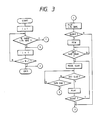
- Fig. 3 is a flowchart illustrating control operations effected by the control unit at the time of timer playback.
- control unit sets a variable i at 1 and detects the presence or absence of the cassette on the storage shelf 11, the variable i representing the position where the cassette corresponding to each of the storage shelves 11 to 15 is stored.
- the cassette detection unit 11 On detecting the designated cassette on the storage shelf 11, the cassette detection unit 11 applies a signal designating the storage shelf 11 to the cassette transfer unit 4, which extracts the cassette from the storage shelf 11 and mounts it in the tape drive unit 3.
- control unit On receiving a signal indicating the completion of the installation of the cassette from the tape drive unit 3, the control unit applies a playback drive signal (play signal) to the tape drive unit 3 to cause the playback operation to be performed.
- a playback drive signal play signal
- the control unit increments the variable i by ne and searches for the desired cassette on the storage shelves 12, 13,.. sequentially in order (until the variable i becomes greater by one than the number of storage shelves) while repeating the playback operation until the desired cassette is detected.
- control unit When a program of, e.g., music is reproduced within a predetermined period of time upon mounting the cassette in the tape drive unit 3 and performing the playback operation, the control unit continues with the playback operation. However, if a silent state continues for a fixed period of time with the reproduction of no program, the control unit sends a rewind drive signal (REW signal) to the tape drive unit 3 to cause the cassette to be rewound.
- REW signal rewind drive signal
- the control unit On receiving a detection signal indicating that the tape has been completely rewound, the control unit applies a drive signal (FF signal) designating a high-speed search operation to the cassette drive unit 3 to carry out a high-speed search operation while detecting the start IDs until the tape end is detected.
- FF signal drive signal
- the control unit When a start ID is detected, the control unit produces a playback drive signal to resume the playback operation and, if the silent state continues for a fixed period of time while a playback operation is being performed, a high-speed search is conducted and the above-described operation is repeated.
- control unit increments the variable i by one as in the case where no cassette is detected on the storage shelf 1, and detects the cassettes sequentially in order on the storage shelves 12, 13,... and performs the above-described operations in the same manner as already described.
- a program of, e.g., music can be played back automatically as far as there exists at least one cassette stored and at least one program recorded on the cassette corresponding to the designated selection.
- a plurality of cassettes are stored on the storage shelves and the presence or absence of a desired cassettes is detected successively during timer playback. If no playback operation is performed for a fixed period of time, the control unit searches through a tape from its head for a program, and a playback operation is performed with respect to the next cassette when no recorded program is found on the preceding one. Accordingly, the trouble of having to repetitively replace the cassettes is eliminated.
- FIG. 4 A second embodiment of the invention will be described with reference to Fig. 4.
- a shelf number designating key 221 to 225 is depressed together with the REC key 211 while a program of, e.g., music is being recorded on a cassette installed in the tape drive unit 3, the recording process is continued on a cassette on the storage shelf designated by the depressed shelf number designating key 221 to 225 after recording on the present cassette is terminated.
- the tape drive unit 3 drives the cassette installed therein and outputs signals indicating the detection of the end and head of the tape and the completion of installation of the cassette therein, in addition to an FG signal indicating the tape reel speed.
- the cassette transfer unit 4 transfers the cassettes from the storage unit 1 to the tape drive unit 3 and vice versa. On receiving a signal indicating the number of a storage shelf in the storage unit 1 and a drive signal, the cassette transfer unit extracts the cassette from the designated storage shelf and mounts it in the tape drive unit 3. On receiving a drive signal while the cassette is mounted in the tape drive unit 3, the cassette transfer unit returns the cassette to the designated storage shelf in the storage unit 1.
- a memory 26 is used to store the shelf number designated by the chosen shelf number designating key 221 to 225 and the control 5 effects normal recording/playback, fast forwarding or rewinding operations in conformity with the instructions from the operating unit 10, as in the previously discussed embodiment.
- the control unit 6 stores in the memory 26 the shelf number designated by the chosen shelf number designating key 221 to 225 during recording, and sends a signal indicating the shelf number stored in the memory 26 and a drive signal to the cassette transfer unit 4 when recording of the present cassette is terminated to cause continuous recording to be carried out.
- control unit 5 Based on an FG signal supplied from the drive unit 3, the control unit 5 computes the remaining time relative for the present cassette for recording and drives the display unit 10 to display a message when the remaining time reaches a predetermined level.
- Fig. 5 is a flowchart illustrating the control operations carried out by the control unit 5. A control operation while recording is being carried out will subsequently be described.
- the shelf number supplied by the chosen shelf number designating key 221 to 225 is stored in the memory 26.
- the display unit 10 provides a display message for calling attention to the decrease of the remaining time to a predetermined value.
- the control unit 5 clears the displayed message from the display unit 10 and, provided the inputs of the shelf designating key 22 and the REC key 211 have been applied, determines the continual recording mode is valid and reads the shelf number stored in the memory 26. After storing data indicative of the cassette in the tape drive unit 3 in the memory 26, the control unit 5 applies the shelf number read from the memory 26 and the drive signal to the tape drive unit 3 to thus effect continuous recording sequentially relative to the designated cassette, and then clears the memory 5.
- the apparatus embodying the present invention is designed so that the user is allowed to confirm the designating number (storage shelf number) of the cassette to be subsequently used for recording while continuous recording is in effect.
- the storage shelf number designated for continuous recording is successively stored in the memory 26 in a storage area S(i) identified by an index i.
- the control unit 5 resets the index i to "0" at the time continuous recording is started and, when an input of a predetermined operating key (e.g., the "+” key) is applied, increments the index i by 1, whereby the display unit 10 is caused to display the storage shelf number stored in the storage area S(i) for a predetermined length of time.
- a predetermined operating key e.g., the "+” key
- the control unit 5 increments the index i by 1 each time the input of the operating key is applied and causes the storage shelf number stored in the memory 26 to be successively displayed by the display unit 10.
- Fig. 6 is a flowchart of the above-described control operations.
- a plurality of cassettes are stored in the storage shelves in the magnetic recording/playback apparatus such as a digital audio tape recorder according to the present invention in such a manner that a storage shelf designated during a recording operation is stored and a recording operation is automatically performed on the designated cassette after the termination of the recording operation on the present cassette. Accordingly, the plurality of cassette are usable for continuous recording.
- Fig. 7 is a flowchart illustrating the control operations effected by the control unit 6 in the third embodiment.
- the control unit applies a signal indicating the number of a predetermined first storage shelf 11 to the cassette transfer unit 4, which in response extracts the cassette stored on the storage shelf 11 and mounts it in the tape drive unit 3 to perform a playback operation.
- the control unit applies a signal indicating the number of a predetermined fifth storage shelf 15 to the cassette transfer unit 4 to cause a recording operation to be performed on the cassette stored on the storage shelf 15.
- control operations refer to normal control.
- timer operation the same control operations are employed in dependence on the operating key activated when the timer circuit 6 outputs a start signal.
- timer playback on the cassette from the first storage shelf 11 is effected in the playback mode, whereas timer recording on the cassette from the fifth storage shelf is carried out in the recording mode.
- the cassette on a predetermined different storage shelf is automatically used according to the recording or playback mode.
- the storage shelves can be divided into positions for dedicated use in recording and playback. Consequently, the trouble resulting from confusing cassettes intended for recording and playback can be reduced, which makes it possible to provide an apparatus offering excellent operability.
- the storage shelves for dedicated use in recording and playback are divided from one another, the operation of setting both the operating key of each mode and the number designating the storage shelf can be dispensed with when recording or playback is carried out. Accordingly, the keyboarding operations are minimized.
- the storage shelves can be divided into two groups for dedicated use in recording and playback and, since the storage shelves for use in recording and playback are predetermined, it is only necessary to operate either key in the recording or playback mode.
- the keyboarding operations are thus minimized, and the operability of the apparatus is improved.
- the shelf number designating keys 221 to 225 are used to designate a storage shelf and then an operating key (REW key 212, etc.) for designating an operating mode process is pressed
- the designated process is automatically applied to the cassette on the designated storage shelf. That is, when the REW key 212 is pressed after the storage shelf designating keys 221, 222 and 223 are successively pressed, for instance, a rewinding operation is performed on the cassettes stored on the storage shelves 11, 12, and 13, respectively, having storage shelf numbers "1", "2" and "3".
- Fig. 8 is a flowchart illustrating control exercised by the control unit 5 of Fig. 4 in accordance with the fourth embodiment.
- an index i identifies a storage area S(i) of the memory 26, which is initially set to "0".
- the control unit increments the index i by 1 and stores the shelf number thus supplied in the storage area S(1) and further determines whether the input of an operating key 211 to216 such as that of the REW key 212 or RENO. key 213 is supplied.
- the control unit successively detects the input of the shelf number designating key 221 to 225 until the input of the operating key 21 is supplied and successively stores the shelf number designated in the respective storage areas S(2), S(3), ... .
- the control unit When the input of an operating key 211 to 216 is supplied, the control unit reads the shelf number from the arrangement storage area S(i) designated by the index i and supplies data indicative of the designated storage shelf to the cassette transfer unit 4. Further, the control unit conducts the process designated by the depressed operating key 211 to 216 (e.g., rewinding or program rewriting).
- control unit decrements the index i by 1 and conducts the same process relative to the next cassette on the storage shelf indicated by the shelf number stored in the storage area S(i). The process is terminated when the index i becomes "0".
- the plurality of storage shelves are thus designated and the desired process relative to the cassette on the designated shelf can be conducted by pressing the operating key only once.
- a plurality of cassettes are stored on the storage shelves in the magnetic recording/playback apparatus in such a manner that the designated storage shelf is stored and the process in the designated mode is successively conducted on the cassette on the storage shelf thus designated. Accordingly, the same process can be carried out on a plurality of cassettes automatically through a simple operation, and moreover the operability of the apparatus is improved due to the minimized keyboarding operation.
- FIG. 9 a circuit incorporated in the tape recording/playback apparatus shown in Fig. 1 in accordance with a fifth embodiment will be explained. It is noted that reference numerals identical to those shown in Fig. 1 refer to identical components, and a further detailed description thereof will be omitted.
- a mechanical drive unit 32 for recording and replaying a cassette selected and transferred from the shelves by a changer unit 31, a rotary head 33, an amplifier 34 for amplifying signals reproduced by the rotary head 33, a signal processing unit 35 for identifying various control signals recorded on a tape and fed from the amplifier 34 and outputting the same, and a control unit 36 for controlling the mechanical drive unit 32, the signal processing unit 35, the changer unit 31 and the display 10 according to the various data signals from the mechanical drive unit 32, the signal processing unit 35 and the operating unit 2, the control unit 36 performing a series of operations in accordance with the procedures shown in the flowcharts shown in Figs. 10 and 11, as will be described below.
- An external synchronizing signal is also supplied to the control unit 36.
- the drive unit is equipped with a sensor for detecting the presence of a cassette.
- the control unit sets the first cassette as an i-th cassette (Step a); monitors whether the i-th cassette is loaded in the holder of the drive unit (Step b); issues instructions as to the examination of next cassette provided the i-th cassette is absent (Step c); monitors whether the next cassette is a final one (Step d); and returns to Step b if the final cassette is absent and again monitors whether still another cassettes is loaded in the holder of the drive unit.
- Step b On detecting a cassette in Step b, the control unit operates to send to the mechanical drive unit 32 a signal for starting the playback of the detected cassette. Consequently, the mechanical drive unit 32 starts replaying the cassette (Step e).
- the control unit 36 monitors the elapsed time (Step f) and transmits a playback stop signal to the mechanical drive unit 32 after a fixed interval, and further proceeds to a Step c in which the playing of the next cassette starts.
- Step f the control unit 36 monitors whether an eject button is pressed (Step g) and, if the eject button is pushed during that period, it terminates the introduction scanning operation (Step h).
- control unit repeats the introduction scanning operation to complete the playback of all cassettes and, since a signal indicating the completion of the playback of all cassettes is issued in Step d, an output for stopping the introduction scanning operation is transmitted.
- the first cassette is selected (Step a) and the cassette thus selected is transferred to the mechanical drive unit 32 for the preparation of tape loading (Step i). If no cassette is present, no loading operation is performed, and therefore the control unit 36 determines the absence of the cassette (Step j) and transmits an unloading signal to the mechanical drive unit (Step k) so as to advance to the condition in which the next cassette is drawn. Accordingly, the control unit 36 shifts to the next Step c to play the next cassette. In case a cassette is detected in Step j, the control unit allows the playback of the cassette thus loaded (Step e), i.e. an operation similar to that shown in Fig. 9 is initiated.
- the cassette loaded into the drive unit after being extracted from the shelves is replayed for a predetermined time, and the cassette is returned to the shelves after completion of the playback operation while the next cassette is continually played in a similar operation so that only the leading ends of all cassettes are played. Accordingly, the contents of all cassettes can be checked without having to manually extract the cassettes one after another to check the labels thereof or to repeatedly play and stop each cassette. The contents of each cassette can thus be confirmed without any troublesome operation.
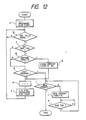
- FIG. 12 A sixth embodiment of the invention will be described with reference to the flowchart of Fig. 12.
- the overall arrangement of the apparatus of the embodiment is the same as that shown in Figs. 1 and 9.
- Step a When a program is played back by designating a plurality of pieces of music from the cassettes in such a manner that the operating unit 2 designates a particular piece from a particular cassette, the cassette thus designated is moved from the shelves to the mechanical drive unit 32, the tape is loaded, and playback is started (Step a).
- the control unit 5 monitors an end signal of the designated piece from the reproduced signal from the cassette being played, i.e., an ST-ID signal, which is a signal designating the head of the piece being played, supplied from the signal processing unit 35 via the rotary head 33 and the amplifier 34 (Step b). Unless the ST-ID signal is supplied from the signal processing unit 35, the tape is allowed to continue to be run until its end is reached.
- an ST-ID signal which is a signal designating the head of the piece being played
- control unit 36 monitors the tape end through the drive unit 32 to detect the leader tape at the tape end (Step c). If the control unit 36 detects the ST-ID signal before detecting the tape end, it determines whether the program has been played back completely (Step d). The control unit 36 further selects another cassette in the next step (Step e), moves the cassette thus selected into the drive unit 32, and loads the tape to have the designated piece reproduced (Step f).
- the control unit 36 instructs the fast feeding and rewinding of the tape prior to proceeding to Step e.
- the playback operation is performed. The process then proceeds to Step e.
- Step c Unless the ST-ID signal indicating the head of the next piece is supplied in Step c, the tape is allowed to move until the tape end is reached. Consequently, the tape end signal is supplied from the drive unit 32 to the control unit 36.
- the control unit 36 determines whether the next program represents a piece on the same cassette or is contained on another cassette (Step g), and, if the next piece is on another cassette, stores the reel number of the present cassette in the memory (Step h).
- the control unit returns to Step e after storing the number in the memory, selects a cassette programmed in the next stage, and starts the playback of the program.
- Step g When the piece programmed in the following stage is on the same cassette in Step g, the control unit returns to Step d and performs the same operation.
- Step i the control unit 36 determines that the program in Step d has been completed. Consequently, the control unit 36 monitors the presence of the cassette stored in Step h and set for rewinding (Step i) and, of any cassette to be rewound is present, moves the cassette from the magazine to the drive unit 32 for loading and performing the rewinding operation (Step j). At this time, the control unit 36 monitors the winding state of the tape from the drive unit 2 (Step k) and, when it detects the winding position signal, returns to Step i to repeat the winding operation of all stored cassettes.
- a cassette is stored when the tape end of the cassette to be replayed according to a program is detected, and at least the cassette thus stored is moved into the drive unit again, rewound completely up to the tape end and returned to the drive unit for rewinding after all cassettes have been completely replayed. Accordingly, the time required to rewind the cassettes is saved at the time the next program is executed. The total search time is thus shortened.
- a seventh embodiment of the invention will be described with reference to the block diagram of Fig. 13 and the flowchart of Fig. 14.
- the seventh embodiment differs from the sixth embodiment by the addition of a tuner unit 37 through which a plurality of broadcast stations and a plurality of timers can be set.
- the control unit 36 supplies power to the tuner unit 37 at times preset by a built-in timer.
- the output signal from the tuner unit 37 is supplied to the rotary head 33.
- the operating unit 2 determines a particular cassette stored in the changer unit (shelves) 31 on which a particular program from a particular broadcast station is recorded for a particular length of time and sets the recording operation a desired number of times. Consequently, the broadcast stations, recording time and the identifying numbers of cassettes thus set are stored in the memory.
- Step a When timer-controlled recording is to be carried out, the control unit 36 executes a first step (Step a) and monitors whether the first timer start time is reached (Step b). In this case, the control unit 36 moves the cassette set corresponding to the set time from the changer unit 31 into the drive unit 32 when it detects the set time and remains in a standby state where the tape can be wound on the rotary head 33 for recording purposes (Step c). The control unit 36 in this state monitors whether a cassette is present in the drive unit 32 (Step d) and simultaneously ascertains whether recording is possible (Step e). When the control unit 36 detects the presence of a cassette and a situation in which recording is possible, it holds the tuner unit 37 on and, while supplying the broadcast signal from the tuner unit 37 to the rotary head 33, starts the recording operation (Step f).
- Step h the control unit 36 monitors whether the recording time set first has terminated and monitors to see whether the end of the cassette being used for recording is reached. If no cassette is detected in Steps d and e, when recording conditions are not met, and further when the recording operation has been completed in Steps g and h, the control unit 36 operates to eject the cassette from the drive unit 32 (Step i) and subsequently proceeds to the next step (Step j) and monitors whether this step is final (Step k). If it is not the final step, the control unit 36 returns to Step b and monitors the timer recording time secondly set.
- the tuner unit 37 may be installed separately and may be operated by instruction signals issued from the control unit 36.
- recording start and terminating times and the identifying number of a cassette to be played during a specified time period are designated on a timer recording basis when timer recording is carried out a plurality of times, and the cassettes are used for recording in the order of the numbers thus designated. Accordingly, recording can be made on cassettes classified as to program use, with the effect of dispensing with the necessity of subsequent editing.
Applications Claiming Priority (14)
| Application Number | Priority Date | Filing Date | Title |
|---|---|---|---|
| JP244409/87 | 1987-09-30 | ||
| JP244407/87 | 1987-09-30 | ||
| JP244410/87 | 1987-09-30 | ||
| JP62244410A JPS6489064A (en) | 1987-09-30 | 1987-09-30 | Magnetic recording and reproducing device |
| JP244408/87 | 1987-09-30 | ||
| JP62244409A JPS6489063A (en) | 1987-09-30 | 1987-09-30 | Magnetic recording and reproducing device |
| JP62244407A JPS6489072A (en) | 1987-09-30 | 1987-09-30 | Magnetic recording/reproducing device |
| JP62244408A JP2794283B2 (ja) | 1987-09-30 | 1987-09-30 | 記録・媒体記録装置 |
| JP245760/87 | 1987-10-01 | ||
| JP62245760A JPH0191364A (ja) | 1987-10-01 | 1987-10-01 | テープレコーダのオートチェンジャ |
| JP62248069A JPH0192954A (ja) | 1987-10-02 | 1987-10-02 | テープレコーダのオートチェンジャ |
| JP248069/87 | 1987-10-02 | ||
| JP257435/87 | 1987-10-14 | ||
| JP62257435A JPH01100768A (ja) | 1987-10-14 | 1987-10-14 | テープレコーダのオートチェンジャ |
Publications (2)
| Publication Number | Publication Date |
|---|---|
| EP0310256A2 true EP0310256A2 (de) | 1989-04-05 |
| EP0310256A3 EP0310256A3 (de) | 1990-11-22 |
Family
ID=27566689
Family Applications (1)
| Application Number | Title | Priority Date | Filing Date |
|---|---|---|---|
| EP19880308232 Withdrawn EP0310256A3 (de) | 1987-09-30 | 1988-09-06 | Aufzeichnungs-/Wiedergabegerät für magnetische Bänder |
Country Status (2)
| Country | Link |
|---|---|
| US (1) | US5469307A (de) |
| EP (1) | EP0310256A3 (de) |
Cited By (6)
| Publication number | Priority date | Publication date | Assignee | Title |
|---|---|---|---|---|
| EP0501343A2 (de) * | 1991-02-28 | 1992-09-02 | Kabushiki Kaisha Toshiba | Vorrichtung zur Gebrauchsverwaltung für mehrere Kassetten |
| EP0501338A2 (de) * | 1991-02-28 | 1992-09-02 | Kabushiki Kaisha Toshiba | Vorrichtung zum Führen eines Zeitgebers |
| WO1995021445A1 (fr) * | 1994-02-07 | 1995-08-10 | Marcel Allot | Procede et module d'assistance pour controler les operations des appareils domestiques d'enregistrement et de lecture d'emissions televisees |
| US5675557A (en) * | 1993-07-29 | 1997-10-07 | Carlos Lores Borras | Integrated mixing system for synchronizing video and audio signals |
| EP0872834A1 (de) * | 1996-10-09 | 1998-10-21 | Sony Corporation | Informationssignalaufzeichnungsmedium gebrauchendes aufzeichnungsgerät |
| US6153411A (en) * | 1998-10-30 | 2000-11-28 | American Water Works Company, Inc. | Methods and kits for detection of Cryptosporidium parvum using immunomagnetic separation and amplification |
Families Citing this family (8)
| Publication number | Priority date | Publication date | Assignee | Title |
|---|---|---|---|---|
| JPH0737369A (ja) * | 1993-07-19 | 1995-02-07 | Sony Corp | 映像信号記録再生装置 |
| US20030002857A1 (en) * | 2000-12-27 | 2003-01-02 | Curtin Steven D. | Electronic write protect detection for video tape recorders |
| WO2004111797A2 (en) * | 2003-06-11 | 2004-12-23 | Touch Automation | Automated business system and method of vending and returning a consumer product |
| WO2011121890A1 (ja) * | 2010-03-29 | 2011-10-06 | パナソニック株式会社 | 光ディスク再生装置 |
| US9438642B2 (en) | 2012-05-01 | 2016-09-06 | Google Technology Holdings LLC | Methods for coordinating communications between a plurality of communication devices of a user |
| US9813262B2 (en) | 2012-12-03 | 2017-11-07 | Google Technology Holdings LLC | Method and apparatus for selectively transmitting data using spatial diversity |
| US9979531B2 (en) | 2013-01-03 | 2018-05-22 | Google Technology Holdings LLC | Method and apparatus for tuning a communication device for multi band operation |
| US10229697B2 (en) | 2013-03-12 | 2019-03-12 | Google Technology Holdings LLC | Apparatus and method for beamforming to obtain voice and noise signals |
Citations (11)
| Publication number | Priority date | Publication date | Assignee | Title |
|---|---|---|---|---|
| US3938190A (en) * | 1974-08-15 | 1976-02-10 | Direct Access Corporation | Storage and retrieval system for magnetic tape cassettes |
| FR2366661A1 (fr) * | 1976-02-25 | 1978-04-28 | Huot Didier | Selecteur de cassettes |
| JPS5715255A (en) * | 1980-07-02 | 1982-01-26 | Sony Corp | Cassette changer |
| JPS5760563A (en) * | 1980-09-29 | 1982-04-12 | Heishiro Tanami | Recording method using a plurality of recording media |
| FR2517863A1 (fr) * | 1981-12-09 | 1983-06-10 | Moulene Daniel | Appareil de traitement d'informations |
| JPS59201262A (ja) * | 1983-04-28 | 1984-11-14 | Pioneer Electronic Corp | オ−トチエンジ機能を有するカセツトデツキ |
| JPS59213062A (ja) * | 1983-05-16 | 1984-12-01 | Nippon Telegr & Teleph Corp <Ntt> | 集合カ−トリツジ記憶装置 |
| FR2570538A1 (fr) * | 1984-09-20 | 1986-03-21 | Electronique Acoustique Ind | Dispositif lecteur de support d'information, notamment cassettes sonores |
| US4622610A (en) * | 1982-01-08 | 1986-11-11 | Mitsubishi Denki Kabushiki Kaisha | Automatic cassette exchanging playback device |
| EP0224465A2 (de) * | 1985-11-29 | 1987-06-03 | Staar Societe Anonyme | Auswahlgerät und- Verfahren für den Abwechslungsmodus eines automatischen Plattenwechslers |
| EP0257534A2 (de) * | 1986-08-23 | 1988-03-02 | GRUNDIG E.M.V. Elektro-Mechanische Versuchsanstalt Max Grundig | Einrichtung zum Aufzeichnen und schnellen Wiederauffinden von Videosignalabschnitten auf einem Magnetband |
Family Cites Families (1)
| Publication number | Priority date | Publication date | Assignee | Title |
|---|---|---|---|---|
| US4779151A (en) * | 1985-04-08 | 1988-10-18 | Odetics, Inc. | Robotic tape cassette handling system with rotary loading and unloading mechanism |
-
1988
- 1988-09-06 EP EP19880308232 patent/EP0310256A3/de not_active Withdrawn
-
1993
- 1993-09-03 US US08/115,790 patent/US5469307A/en not_active Expired - Fee Related
Patent Citations (11)
| Publication number | Priority date | Publication date | Assignee | Title |
|---|---|---|---|---|
| US3938190A (en) * | 1974-08-15 | 1976-02-10 | Direct Access Corporation | Storage and retrieval system for magnetic tape cassettes |
| FR2366661A1 (fr) * | 1976-02-25 | 1978-04-28 | Huot Didier | Selecteur de cassettes |
| JPS5715255A (en) * | 1980-07-02 | 1982-01-26 | Sony Corp | Cassette changer |
| JPS5760563A (en) * | 1980-09-29 | 1982-04-12 | Heishiro Tanami | Recording method using a plurality of recording media |
| FR2517863A1 (fr) * | 1981-12-09 | 1983-06-10 | Moulene Daniel | Appareil de traitement d'informations |
| US4622610A (en) * | 1982-01-08 | 1986-11-11 | Mitsubishi Denki Kabushiki Kaisha | Automatic cassette exchanging playback device |
| JPS59201262A (ja) * | 1983-04-28 | 1984-11-14 | Pioneer Electronic Corp | オ−トチエンジ機能を有するカセツトデツキ |
| JPS59213062A (ja) * | 1983-05-16 | 1984-12-01 | Nippon Telegr & Teleph Corp <Ntt> | 集合カ−トリツジ記憶装置 |
| FR2570538A1 (fr) * | 1984-09-20 | 1986-03-21 | Electronique Acoustique Ind | Dispositif lecteur de support d'information, notamment cassettes sonores |
| EP0224465A2 (de) * | 1985-11-29 | 1987-06-03 | Staar Societe Anonyme | Auswahlgerät und- Verfahren für den Abwechslungsmodus eines automatischen Plattenwechslers |
| EP0257534A2 (de) * | 1986-08-23 | 1988-03-02 | GRUNDIG E.M.V. Elektro-Mechanische Versuchsanstalt Max Grundig | Einrichtung zum Aufzeichnen und schnellen Wiederauffinden von Videosignalabschnitten auf einem Magnetband |
Non-Patent Citations (6)
| Title |
|---|
| FERNSEH UND KINO TECHNIK. vol. 36, no. 5, May 1982, BERLIN DE pages 171 - 177; HEDTKE et al.: "Dezentrales Mikroprozessorsystem am Beispiel eines Multikassettenautomaten" * |
| JOURNAL OF THE SOCIETY OF MOTION PICTURE ENGINEERS. vol. 88, no. 4, April 1979, NEW YORK US pages 221 - 223; kazama et al.: "Atomatic Storage and Retrieval of Videotaped Programs" * |
| PATENT ABSTRACTS OF JAPAN vol. 6, no. 137 (P-130)(1016) 24 June 1982, & JP-A-57 060 563 (HEISHIROU TANAMI) 12 April 1982 * |
| PATENT ABSTRACTS OF JAPAN vol. 6, no. 79 (P-115)(957) 18 May 1982, & JP-A-57 015 255 (SONY K.K.) 26 January 1982 * |
| PATENT ABSTRACTS OF JAPAN vol. 9, no. 68 (P-344)(1791) 28 March 1985, & JP-A-59 201 262 (PIONEER K.K.) 14 November 1984 * |
| PATENT ABSTRACTS OF JAPAN vol. 9, no. 83 (P-348)(1806) 12 April 1985, & JP-A-59 213 062 (NIPPON DENSHIN DENWA KOSHA) 01 December 1984 * |
Cited By (13)
| Publication number | Priority date | Publication date | Assignee | Title |
|---|---|---|---|---|
| US5469308A (en) * | 1991-02-28 | 1995-11-21 | Kabushiki Kaisha Toshiba | Management apparatus for a plurality of cassettes |
| EP0501338A2 (de) * | 1991-02-28 | 1992-09-02 | Kabushiki Kaisha Toshiba | Vorrichtung zum Führen eines Zeitgebers |
| US5343450A (en) * | 1991-02-28 | 1994-08-30 | Kabushiki Kaisha Toshiba | Timer operation management apparatus |
| EP0501343A3 (en) * | 1991-02-28 | 1994-09-07 | Toshiba Kk | Use management apparatus for a plurality of cassettes |
| EP0501338A3 (en) * | 1991-02-28 | 1994-09-28 | Toshiba Kk | Timer operation management apparatus |
| EP0501343A2 (de) * | 1991-02-28 | 1992-09-02 | Kabushiki Kaisha Toshiba | Vorrichtung zur Gebrauchsverwaltung für mehrere Kassetten |
| US5675557A (en) * | 1993-07-29 | 1997-10-07 | Carlos Lores Borras | Integrated mixing system for synchronizing video and audio signals |
| FR2716063A1 (fr) * | 1994-02-07 | 1995-08-11 | Allot Marcel Yves | Procédé d'assistance pour l'enregistrement et la lecture d'émissions télévisées. |
| WO1995021445A1 (fr) * | 1994-02-07 | 1995-08-10 | Marcel Allot | Procede et module d'assistance pour controler les operations des appareils domestiques d'enregistrement et de lecture d'emissions televisees |
| EP0872834A1 (de) * | 1996-10-09 | 1998-10-21 | Sony Corporation | Informationssignalaufzeichnungsmedium gebrauchendes aufzeichnungsgerät |
| EP0872834A4 (de) * | 1996-10-09 | 1999-12-29 | Sony Corp | Informationssignalaufzeichnungsmedium gebrauchendes aufzeichnungsgerät |
| US6153411A (en) * | 1998-10-30 | 2000-11-28 | American Water Works Company, Inc. | Methods and kits for detection of Cryptosporidium parvum using immunomagnetic separation and amplification |
| US6395517B1 (en) | 1998-10-30 | 2002-05-28 | American Water Works Company, Inc. | Methods and kits for detection of cryptosporidium parvum |
Also Published As
| Publication number | Publication date |
|---|---|
| US5469307A (en) | 1995-11-21 |
| EP0310256A3 (de) | 1990-11-22 |
Similar Documents
| Publication | Publication Date | Title |
|---|---|---|
| US5418622A (en) | Apparatus for recording and reproducing audio and video signals in accordance with a broadcast schedule | |
| US5469307A (en) | Magnetic tape recording/playback apparatus for automatically detecting a desired program | |
| WO1990001838A1 (en) | Recovery recorder system, particularly commercial radio/tv broadcast recovery recorder system | |
| JP2000123463A (ja) | マルチディスクプレーヤ | |
| JPS61172238A (ja) | ビデオテ−プレコ−ダの自動頭出し装置 | |
| US5426534A (en) | Multiple-deck magnetic information recording reproducer | |
| JP2764926B2 (ja) | カセット自動供給選択再生装置 | |
| US5179543A (en) | Dubbing apparatus for audio equipment | |
| JPH09198853A (ja) | 再生装置 | |
| JP3419854B2 (ja) | 送出システム | |
| KR100221723B1 (ko) | 브이시알 시스템에서 제로스톱 기억처리 방법 | |
| KR0157523B1 (ko) | 예약녹화시 테이프 잔량 부족분 처리방법 | |
| JPS5819778A (ja) | 自動選曲装置 | |
| JPH07141838A (ja) | 番組送出装置 | |
| JPH0430713Y2 (de) | ||
| JP3227723B2 (ja) | テープカセット自動供給選択再生装置 | |
| KR900007021B1 (ko) | 녹화 초기위치 자동 되감기 방법 | |
| KR100276447B1 (ko) | 오디오시스템의 테이프 레코딩방법 | |
| JPH035938A (ja) | 磁気記録再生装置 | |
| JPH01319165A (ja) | 記録媒体のオートチェンジャ装置 | |
| JPH0335455A (ja) | ディジタル・オーディオ・テープレコーダ | |
| GB2239551A (en) | Tape playing device and method | |
| JPH03248366A (ja) | ビデオテープレコーダ | |
| JPH0831043A (ja) | 磁気記録及び/または再生装置のテープリワインド方法 | |
| JPH0519216B2 (de) |
Legal Events
| Date | Code | Title | Description |
|---|---|---|---|
| PUAI | Public reference made under article 153(3) epc to a published international application that has entered the european phase |
Free format text: ORIGINAL CODE: 0009012 |
|
| AK | Designated contracting states |
Kind code of ref document: A2 Designated state(s): DE FR GB |
|
| PUAL | Search report despatched |
Free format text: ORIGINAL CODE: 0009013 |
|
| AK | Designated contracting states |
Kind code of ref document: A3 Designated state(s): DE FR GB |
|
| RHK1 | Main classification (correction) |
Ipc: G11B 27/02 |
|
| 17P | Request for examination filed |
Effective date: 19910503 |
|
| 17Q | First examination report despatched |
Effective date: 19930901 |
|
| STAA | Information on the status of an ep patent application or granted ep patent |
Free format text: STATUS: THE APPLICATION HAS BEEN WITHDRAWN |
|
| 18W | Application withdrawn |
Withdrawal date: 19940113 |