EP0314513A2 - Ink jet recording apparatus - Google Patents
Ink jet recording apparatus Download PDFInfo
- Publication number
- EP0314513A2 EP0314513A2 EP88310196A EP88310196A EP0314513A2 EP 0314513 A2 EP0314513 A2 EP 0314513A2 EP 88310196 A EP88310196 A EP 88310196A EP 88310196 A EP88310196 A EP 88310196A EP 0314513 A2 EP0314513 A2 EP 0314513A2
- Authority
- EP
- European Patent Office
- Prior art keywords
- ink
- rubbing
- cleaning
- ink jet
- recording apparatus
- Prior art date
- Legal status (The legal status is an assumption and is not a legal conclusion. Google has not performed a legal analysis and makes no representation as to the accuracy of the status listed.)
- Granted
Links
Images


Classifications
-
- B—PERFORMING OPERATIONS; TRANSPORTING
- B41—PRINTING; LINING MACHINES; TYPEWRITERS; STAMPS
- B41J—TYPEWRITERS; SELECTIVE PRINTING MECHANISMS, i.e. MECHANISMS PRINTING OTHERWISE THAN FROM A FORME; CORRECTION OF TYPOGRAPHICAL ERRORS
- B41J2/00—Typewriters or selective printing mechanisms characterised by the printing or marking process for which they are designed
- B41J2/005—Typewriters or selective printing mechanisms characterised by the printing or marking process for which they are designed characterised by bringing liquid or particles selectively into contact with a printing material
- B41J2/01—Ink jet
- B41J2/135—Nozzles
- B41J2/165—Preventing or detecting of nozzle clogging, e.g. cleaning, capping or moistening for nozzles
- B41J2/16505—Caps, spittoons or covers for cleaning or preventing drying out
- B41J2/16508—Caps, spittoons or covers for cleaning or preventing drying out connected with the printer frame
-
- B—PERFORMING OPERATIONS; TRANSPORTING
- B41—PRINTING; LINING MACHINES; TYPEWRITERS; STAMPS
- B41J—TYPEWRITERS; SELECTIVE PRINTING MECHANISMS, i.e. MECHANISMS PRINTING OTHERWISE THAN FROM A FORME; CORRECTION OF TYPOGRAPHICAL ERRORS
- B41J2/00—Typewriters or selective printing mechanisms characterised by the printing or marking process for which they are designed
- B41J2/005—Typewriters or selective printing mechanisms characterised by the printing or marking process for which they are designed characterised by bringing liquid or particles selectively into contact with a printing material
- B41J2/01—Ink jet
- B41J2/135—Nozzles
- B41J2/165—Preventing or detecting of nozzle clogging, e.g. cleaning, capping or moistening for nozzles
- B41J2/16517—Cleaning of print head nozzles
- B41J2/16535—Cleaning of print head nozzles using wiping constructions
- B41J2/16538—Cleaning of print head nozzles using wiping constructions with brushes or wiper blades perpendicular to the nozzle plate
Definitions
- This invention relates to an ink discharge recording device in an ink jet recording apparatus, and in particular to an ink discharge recovery device provided with cleaning means for cleaning the discharge port surface of a recording head.
- an ink jet recording apparatus as means for preventing the ink discharge ports from clogging due to the increase in viscosity of ink caused by evaporation of the ink solvent or to the adherence of dust or the creation of bubbles, there is a construction as described, for example, in U.S. Patent No. 4,045,802 and U.S. Patent No. 4,603,931, wherein the ink discharge port surface of the recording head is covered with a cap to thereby shield the ink discharge port surface from the atmosphere and keep the discharge ports in a good condition, and a construction in which a discharge recovery device for causing ink to be discharged by a suction pump or the like is provided.
- Such a capping operation and such a discharge recovery operation are usually effected when a carriage is at its home position.
- liquid drops of relatively low viscosity such as ink drops adhering to the surroundings of the discharge ports and dewdrops formed on the surroundings of the discharge ports by the rise of the humidity in the apparatus can be removed by the discharge recovery operation using suction or the like.
- the discharge recovery device when an attempt is made to resume recording after recording has been ceased or stopped for a long time, the occurrence of non-discharge is eliminated by the discharge recovery device, but the direction of flight of ink deviates and thus, it has become impossible to cause ink droplets to adhere to a accurate positions on the surface of a recoridng medium and images formed thereon have sometimes been disturbed.
- the sponge retains water content therein and therefore, the rise of the humidity in the apparatus is expedited and the total amount of water drops adhering to the surroundings of the discharge ports due to dew formation is increased, and this has increased the wiping operation by the blade and thus, this could not be a radical improvement.
- the inventors have carried out recording tests under all conditions while observing the surroundings of the discharge ports of the recording head and have deeply sought after the causes of the occurrence of unsatisfactory ink discharge.
- Such an ink film ID′ has often been created when non-recording has lasted long.
- unsatisfactory discharge occurs when recording is resumed after a long downtime of recording, but the cause thereof has been regarded as being attributable to an increase in the viscosity of ink or entry of air into ink.
- the causes of non-discharge are the clogging resulting from an increase in the viscosity of ink and entry of air, but nobody has been aware that the cause of the deviation of the direction of ink discharge is attributable to the film of ink as noted above.
- such a film has reduced the ink-repellent property of the discharge port surface and has induced a state in which ink is ready to adhere.
- the present invention has been made in view of the above-noted problems. It is an object of the present invention to provide an ink jet recording apparatus in which ink drops, water drops, dust, etc. adhering to the vicinity of discharge ports can be remove and a film caused by the ink adhering thereto can also be removed.
- It is another object of the present invention to provide an ink jet recording apparatus having a carriage for scanning a recording head having discharge ports for discharging ink therethrough relative to a recording medium, and heating means for heating said recording medium, characterized by blade means provided outside the recording area for wiping the vicinity of said discharge ports on the basis of a predetermined sequence during the recording operation, rubbing means differing from said blade means and provided at a position outside the recording area whereat it can contact with said recording head, and means for moving said carriage to the vicinity of a position at which it can contact with said rubbing means, said means producing a command for cleaning the vicinity of said discharge ports by said rubbing means when a predetermined signal is input to said means.
- the present invention may be of any construction which can achieve the objects of the invention, and may of course permit combinations of constituents in the embodiments which will hereinafter be described, the timing of the cleaning operation and the sequence, as well as may be one which effects sequence control comprising a combination of further constituents.
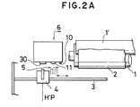
- Figures 2A - 2C are a schematic plan view, a schematic perspective view and a schematic perspective view, respectively, showing the essential portions of an ink jet recording apparatus according to the present invention.
- a guide shaft 3 is installed forwardly of paper 2 as a recording medium backed up by a platen 1, and an ink jet recording head 5 is carried on a carriage 4 movable along the guide shaft 3.
- Heating means 1′ such as a fixating heater is provided on a discharge route for the paper 2 after recording.
- An electro-thermal converting member, not shown, as energy generating means for generating energy utilized to discharge ink is provided in the recording head 5, and by causing heat energy to act on the ink, the ink is discharged.
- Such a recording head is preferably used for its numerous merits, but may be one using a piezo element or the like.
- the recording head may be of a construction integrally having an ink tank for containing ink therein, or may be a full line type head in which a number of discharge ports are disposed widthwisely of the recording medium.
- the discharge port surface of the above-described recording head is subjected, for example, to ink-repellent surface treatment.
- a discharge recovery device (of the pump suction type in the illustrated embodiment) 6 for the recording head 5 is provided at the home position HP of the carriage 4.
- This discharge recovery device is provided with capping means 7 having a cap 30 driven forward and backward relative to the recording head 5 and covering the front face (the orifice portion) of the recording head at the forwardly moved position thereof, and a pump 9 for sucking the ink from the orifices (the ink discharge ports) through the capping means 7.
- the operation of this recovery device is effected by the input or the like of a key switch. not shown.
- a flexible blade 10 for wiping the vicinity of the discharge ports (for example, the discharge port surface) of the recording head 5 is mounted on a side of the discharge recovery device 6.
- the blade refers to a member which makes substantially line contact with the discharge port surface, that is, whose area of contact CA is small (see Figure 2B), and rubbing means refers to a means whose area of contact CA is great (see Figure 2C).
- a rubbing mechanism 11 movable forward and backward with the capping means 7 is provided on a side of the capping means 7.
- This rubbing mechanism 11 is means for rubbing the vicinity of the discharge ports (for example, the discharge port surface) of the recording head 5, and has a greater area of contact with the discharge port surface than the aforementioned blade.
- the rubbing operation of the rubbing mechanism 11 may be accomplished by the cap operation and the carriage operation.
- Figure 3 is a schematic perspective view of the discharge recovery device 6
- Figure 4 is a schematic front view corresponding to Figure 3
- Figure 5 is a schematic side view corresponding to Figure 3
- Figure 6 is a schematic elevational view of a worm wheel portion forming the drive mechanism in Figure 3.
- the pump 9 is mounted on a frame 15, and a worm wheel 12 rides on the piston 9A ( Figure 6) of the pump 9, and a worm wheel shaft 12A integral with the worm wheel 12 is supported by a lid 16.
- the worm wheel 12 is formed with a worm wheel cam 13, and when the worm wheel 12 is rotated, the worm wheel cam 13 comes into abutment against a fixed cam 13A ( Figure 6), whereby the worm wheel 12 is moved downward and the piston 9A of the pump 9 is depressed.
- the pump 9 is driven by the depression of this piston 9A and generates a negative suction force lower than the atmospheric pressure.
- the return of the piston 9A (the discontinuance of the operation of the pump 9) is accomplished by a spring (a return spring), not shown, in the pump 9.
- the forward and backward movement of the capping means 7 with respect to the recording head 5 is accomplished by the engagement between the inner surface cam (another cam surface, not shown) of the worm wheel cam 13 and the capping means.
- the cap 30 formed, for example, of silicone, butyl chloride or the like adapted to be sealingly urged against the orifice surface is provided on the front face of the capping means.
- the blade 10 is controlled by a combination of the forward and reverse rotation of the cam 13, a blade stop lever and the carriage operation so that it is moved forward by a predetermined amount when the capping means 7 is brought into its opened condition by rotation of the cam 13.
- the blade 10 may be fixed at its forwardly moved position.
- Figure 7 is a partial plan view showing the assembled state of the rubbing mechanism 11.
- the rubbing mechanism 11 comprises a block 11B supported on a base member 7A integral with the capping means 7 for movement back and forth, and a rubbing member 11C attached to the block 11B with a plate-like porous material interposed in a U-shape therebetween, said rubbing member 11C being assembled in such a manner that the current surface portion thereof is protruded by a predetermined amount toward the recording head side by a compression spring 11A mounted between the block 11B and the base member 7A.
- the anti-slippage of the block 11B from the base member 7A is accomplished by a snap ring 11D.
- the material forming the rubbing member 11C may preferably be a porous material, and more preferably be a material having more or less soft texture and a water-absorbing property, such as urethane, polyvinyl alcohol (PVA), polyethylene (PE), polyvinyl formal, polypropylene or polyurethane, and unwoven fabric or the like is also usable as the rubbing member.
- PVA polyvinyl alcohol
- PE polyethylene
- PE polyvinyl formal
- polypropylene or polyurethane and unwoven fabric or the like is also usable as the rubbing member.
- Figure 8 is a flow chart of the operation procedure when the rubbing operation of the orifice portion of the recording head 5 is effected by the above-described rubbing mechanism 11.
- step F1 the recording head 5 is first moved to the home position HP, and the capping means 7 is kept as it is or is once closed, whereafter it is opened (step F2).
- step F3 the carriage 4 is moved to the right as viewed in Figure 1 by a predetermined ith the capping means 7 opened, and is set in a position wherein the rubbing member 11C can bear against the orifice portion of the recording head 5.
- step F4 the capping means 7 is moved forward to a point corresponding to the closed position and the rubbing member llC of a porous material is urged against the orifice portion by the spring 11A.
- step F5 the carriage 4 is further moved to the right as viewed in Figure 2 with the rubbing member 11C urged against the orifice portion, and the rubbing member 11C is slidden while rubbing the orifice surface. Thereby, a very thin adhering film or the like produced by the desiccation of pools of ink on the orifice surface is removed.
- the wetting property of the orifice surface can be maintained constant and stable ink discharge can be realized.
- step F6 the capping means 7 is moved backward, and at step F7, the recording head 5 is returned to the home position HP.
- the ink discharge recovery device 6 has various recovering functions.
- the discharge recovery device has various recovering functions such as the discharge recovery for effecting the charge of ink into the ink supply system, the recording head 5 and a sub-tank provided between the recording head and a main tank containing the ink therein and the discharge of ink increased in viscosity and bubbles, and the recovery for dissolving the ink increased in viscosity and solidified ink by a three-way valve mechanism 20 ( Figure 5) for directing the ink from the sub-tank in the ink supply system to the cap and a vent mechanism 21 ( Figure 5).
- a control system is constructed so that always stable ink discharge can be easily and reliably obtained correspondingly to various conditions of use.
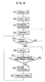
- FIG. 9 is a flow chart showing the sequence control operation of the recovery operation.
- the power switch of the ink jet recording apparatus is closed, the pump 9 is driven and the ink is sucked from the discharge port through the cap 30 and the elimination of the clogging of the discharge ports, the discharge of bubbles, etc. are effected (step S2).
- step S3 capping is released and the above-described rubbing operation is performed, whereafter capping is again effected at the home position and the apparatus becomes ready for the recording operation (step S4).
- a print command comes upon inputting of a recording signal, capping is released and recording is effected (step S6).
- step S7 When a predetermined time (e.g., 10 to 20 sec.) passes after recording has been started (step S7), recording is interrupted and the recording head is moved toward the home position. At this time, the blade 10 is moved forward toward the discharge port surface of the recording head 5. The recording head 5 is moved from the recording area side to the home position side relative to the blade 10 thus moved forward, whereby the recording head is wiped (step S8). Thereafter, at the home position, predischarge of the ink in the cap 30 is effected (step S9), and the recording head 5 continues to be moved to the recording area, thus resuming recording.
- a predetermined time e.g. 10 to 20 sec.
- the cleaning of the discharge port surface by the rubbing means is effected on the basis of a predetermined input signal independently of the cleaning by the blade. That is, the cleaning by the rubbing means is effected only after a long downtime of recording such as the time of power-ON, whereby deterioration of the rubbing means is prevented and efficient release of unsatisfactory discharge conforming to the objects to be removed (ink drops and ink film) can be accomplished.
- the timing of the cleaning by the rubbing means for example, the aforedescribed rubbing function for the orifice surface of the recording head 5 may be omitted in the automatic recovery during the power-ON, and various control sequences may also be designed so that as by effecting the cleaning by the rubbing means during the recovery operation in conformity with a signal produced by the depression of a key switch for effecting a recovery operation differing from the ordinary recovery during the unpacking of the recording apparatus or after a long downtime of the apparatus, the function of the rubbing means is kept good and the time for the recovery operation is made necessary minimum and the amount of ink consumed is minimized.
- the rubbing mechanism 11 is of a structure supported by a spring and having back-lash relative to the capping means 7, and is designed such that when it bears against the recording head 5, it is moved backward by spring displacement and the bearing surface thereof becomes proper.
- the control or the like of the recovery mechanism such as the capping means 7 and the suction pump 9 and of the cleaning means is executed by detecting the position of the cam (the worm wheel cam) 13 by the contact 17 ( Figure 4) of a limit switch or the like, setting the driving pulse and controlling the angle of rotation of the cam 13.
- the aforedescribed rubbing operation for the orifice portion is a part of the recovery sequence, and various combinations are possible such as effecting the rubbing operation after predischarge is effected from the recording head 5 to the rubbing member (porous material) 11C and effecting the rubbing operation before or after the sucking operation by the pump 9.
- the rubbing means 11 is operatively associated with the capping means 7, but alternatively, these may be individually controlled without being operatively associated with each other.
- the present invention is not restricted to a serial type recording apparatus in which the recording head 5 is reciprocally moved to the left and right by the carriage 4, but may also be applied to a line print type recording apparatus.
- Figure 10 is a schematic perspective view showing the essential portions of a rubbing mechanism for the line head of a line print type ink jet recording apparatus.
- Figure 10 shows an ink jet recovery device using arms 53 and 53 changed over to back and forth by a drive source 51 such as a solenoid and a return spring 52 and a long rotatable roll type rubbing member (porous material) 54 to rub the front surface of a line head (ink jet head) 55, i.e., the surface in which orifices 56 are arranged.
- a drive source 51 such as a solenoid and a return spring 52 and a long rotatable roll type rubbing member (porous material) 54 to rub the front surface of a line head (ink jet head) 55, i.e., the surface in which orifices 56 are arranged.
- the porous material 54 is made into a rotatable member and therefore, abrasion can be reduced.
- Figure 11 shows a rubbing mechanism in which a roll type rubbing member (porous material) 62 rotatable about a vertical axis is mounted between two upper and lower wires 61 and 61 and the wires 61 and 61 are driven to the left and right by a motor or the like to thereby slide the rubbing member 62 while the rubbing member 62 bears against the orifice portion in the front surface of the line head (not shown).
- a roll type rubbing member (porous material) 62 rotatable about a vertical axis is mounted between two upper and lower wires 61 and 61 and the wires 61 and 61 are driven to the left and right by a motor or the like to thereby slide the rubbing member 62 while the rubbing member 62 bears against the orifice portion in the front surface of the line head (not shown).
- Figure 12 is a plan view showing the essential portions of still another embodiment of the present invention.
- This embodiment is such that a block shaft 11E perpendicular to a block 11B supported on the base plate 7A of the capping means 7 is provided and a roll-like rotatably rubbing member 11C of porous material is rotatably and interchangeably mounted in such a manner as to be dropped onto the block shaft 11E from above.
- Figure 13 shows another example of the structure of the rubbing mechanism 11 in which the rubbing member 11C of porous material is formed integrally with the rubber cap 30 fitted to the front face of the capping means 7.
- a cap clip portion 30A which is in intimate contact with the circumference of the orifice portion of the recording head 5 is formed around the cap portion of the rubber cap 30.
- the rubbing member 11C is formed of a soft porous material protruding in a semi-cylindrical shape sideways of the cap clip portion 30A on the front face of the rubber cap 30, as shown.
- the resiliency of the cap spring 7B ( Figures 5 and 13) of the capping means 7 and the elasticity of the rubber cap 30 itself can be utilized to cause the rubbing member 11C to bear against the orifice portion with a desired pressure force and therefore, the rubbing member mounting mechanism comprising the spring 11A, the block 11B and the snap ring 11D shown in Figure 7 can be eliminated to thereby reduce the number of parts of the rubbing mechanism 11 and simplify the structure thereof.
- the mechanism 11 discretely from the operation of the blade, the mechanism 11 operatively associated with the capping means 7 of the ink discharge recovery device 6 and rubbing the orifice surface of the recording head 5 as a part of a series of recovery sequences is provided and the recovery operation is performed by the utilization of the rubbing operation of the rubbing mechanism 11 and the operation of the carriage and therefore, pools of ink can be removed and an ink film produced by the desiccation or the like of the pools of ink can also be removed easily and reliably by a simple control circuit and a simple drive system, and it has become possible to keep the wetting property of the orifice portion of the recording head constant and realize stable ink discharge.
- the orifice portion of the recording head 5 can be rubbed by the rubbing member (porous material) 11C, 54, 62 and therefore, the wetting property (the ink-repellent property) of the orifice portion can always be easily maintained constant, and it has become possible to eliminate any printing twist which makes the shooting point of the ink irregular.
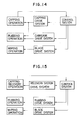
- Figure 14 is a block diagram for effecting the rubbing operation.
- the rubbing operation can be accomplished by another drive system without the utilization of the carriage operation.
- the present invention can also be carried out by other various suitable sequences than the above-described sequences.
- Figure 16 shows the construction of the essential portions of an ink jet recording apparatus according to a sixth embodiment of the present invention.
- the basic construction of this embodiment is similar to that of the previously described embodiment, but it will be described again.
- the reference numeral l designates a platen forming a recording surface by a cylindrical member
- the reference numeral 2 denotes recording paper twined around the platen 1 and having its recording position thereof moved by rotation of the platen 1.
- the reference numeral 3 designates a guide shaft
- the reference numeral 4 denotes a carriage
- the reference numeral 5 designates a recording head.
- the carriage 4 is moved along the guide shaft 3 by the drive of a motor, not shown, and with this movement, the recording head 5 carried on the carriage 4 records images on the recording paper 2.
- HP indicates the home position of the carriage 4, and at the home position HP, an ink discharge recovery device 6 is disposed in such a manner as to be opposed to the discharge port surface of the recording head 5.
- the ink discharge recovery device 6 is comprised of capping means 7 movable forward and backward in opposed relationship with the recording head 5 and hermetically sealing the discharge port surface of the recording head 5 in the forwardly moved position thereof, and a pump 9 driven by a discharge recovering operation lever, not shown, and sucking ink from the ink discharge ports through the capping means 7.
- a flexible blade 10 for wiping the ink discharge port surface of the recording head 5.
- the reference numeral 11 designates a rubbing mechanism disposed on a portion of the surface of the capping means 7 which is opposed to the recording head 5. The rubbing mechanism moves with forward and backward movement of the capping means 7.
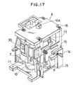
- Figures 17, 18 and 19 are a schematic perspective view, a schematic front view and a schematic side view, respectively, of the ink discharge recovery device.
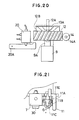
- Figure 20 is a schematic side view showing the details of a pump driving mechanism in the ink discharge recovery device.
- the reference numeral 15 designates a frame forming the bottom plate of the ink discharge recovery device 6,
- the reference character 9A denotes the piston of a pump 9
- the reference numeral 12 designates a worm wheel
- the reference character 12A denotes a worm wheel shaft
- the reference numeral 16 designates a lid.
- the pump 9 is mounted on the frame 15, and the piston 9A and the worm wheel 12 are connected together, and the worm wheel shaft 12A is supported on the lid 16 forming a part of the frame 15.
- the worm wheel 12 and the piston 9A are integral with each other and are vertically movable along the worm wheel shaft 12A, and are biased upwardly by a spring or the like, not shown, in the pump 9.
- the reference numeral 13 designates a cam mechanism engaged with the capping means 7, and this cam mechanism 13 is driven by a motor, not shown. Thereby, forward and backward movement of the capping means 7 is accomplished. Also, the blade 10 is driven by the cam of the cam mechanism 13, and by appropriately controlling the rotation thereof, a position opposed to the capping means 7 is defined.
- the reference numeral 12D designates a worm for transmitting to the worm wheel 12 the drive force transmitted through the worm shaft 14 shown in Figure 17, thereby rotating the worm wheel 12.
- the reference character 12B denotes a worm wheel cam mounted on the worm wheel 12, and the reference character 13A designates a fixed cam fixed to the lid 16.
- Figure 21 is a top plan view showing the details of the rubbing mechanism.
- the reference character 11B designates a block rotatably mounted on a shaft disposed at a predetermined location in the capping means 7.
- the reference character 11C denotes a porous member mounted in a U-shape along the block 11B.
- This porous member 11C may preferably be formed of soft texture comprising a material such as urethane, PVA or PE.
- the reference character 11E designates a base forming the body of the rubbing means 11, and the reference character 11A denotes a leaf spring attached to the base 11E to bias the block 11B by a predetermined amount.
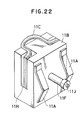
- FIG 22 is a perspective view showing the details off a holding member for the porous member 11C.
- L-shaped grooves 11H are formed at two locations in the block 11B, and the porous member 11C is embedded in a U-shape along these grooves.
- the porous member 11C is exposed at a portion of the block 11B, and the discharge port surface of the recording head 5 is rubbed by this exposed portion.
- Leaf springs 11A are disposed at two locations on that side of the block 1B which is opposite to the side on which the porous member 11C is exposed, and the leaf springs 11A are brought into contact with the base 11E shown in Figure 21.
- a dowel 11F is also slidably engaged with a hole formed in the base 11E, and when rubbing the discharge port surface, the block 11B is moved in the driection of arrow G indicated in Figure 21 while being subjected to the bias of the leaf springs 11A.
- the life of the porous member 11lC of the rubbing means 11 is considerably short as compared with the life of the head and therefore, if it is used beyond its life, the porous surface will become coarse and flully and the rubbing effect will become incomplete. So, according to the experiment carried by the inventors, the life of this porous member 11C substantially corresponds to the time during which the ink in the ink cartridge is consumed, and if the porous member 11C is interchanged during the interchange of the ink cartridge, the rubbing effect can always be maintained and it will be possible to prevent printing twist or the like and thereby prevent deterioration of the quality of recorded images.
- ink cartridge holders 101 are attached to the base 100 of the recording apparatus, and guide grooves 101a for the ink cartridge 102 are formed in the holders 101.
- the ink cartridge 102 is pushed in along the guide grooves 101a by a predetermined stroke in the direction of arrow.
- the rubbing mechanism 11 is made integral with the upper portion of the ink cartridge 102 and therefore, the rubbing mechanism 11 will strike against the base 100 of the recording apparatus and the ink cartridge 102 will become uninsertable. So, by breaking the rubbing mechanism 11 at its root portion 11J, the rubbing mechanism 11 and the ink cartridge 102 are separated from each other and here, for the first time, the insertion of the ink cartridge 102 becomes possible. The separated rubbing mechanism 11 is interchanged with the old rubbing mechanism by the user, and the problem of the deteriorated quality of recording caused by forgotten interchange is solved.
- step S11 When at step S11, the power switch is closed, the pump is driven and the ink is sucked from the discharge ports (step S12), whereafter the recording standby condition is brought about, but if at this time, at step S13, there are the input of a switch provided in the apparatus and the inputting of a rubbing means driving signal from a host computer, the rubbing operation is performed as in the aforedescribed first embodiment, and the ink film is removed (step S14).
- the recording head is again capped and enters the recording standby condition (step S15).
- a recording command is given by the inputting of a recording signal
- the recording head is reciprocally moved in the recording area and discharges the ink to thereby accomplish recording (step S17).
- the cleaning by the blade takes place to remove the ink drops or the like on the discharge port surface.
- the recording of a predetermined number of lines may be printing in one direction effected a plurality of times, or printing in both directions effected a plurality of times.
- the cleaning switch of the rubbing means may be the same as the switch for effecting the suction recovery (PUMP ON) when the apparatus is in power-ON condition, and the rubbing operation and the suction recovery operation may be effected in association with each other.
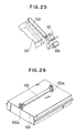
- Figure 25 schematically shows the construction of a rubbing mechanism in the case of a line printer, and more particularly shows an example in which a long rotatable porous member 103 corresponding to a recording head is caused to bear against the ink discharge port surface of a line head 122 by the operation of a solenoid 120 and a spring 121.
- the rotatable porous member 103 is removably mounted relative to a support member 123.
- Figure 26 shows a rotatable porous member 103 which is made integral with an ink cartridge 102 in the case of the construction shown in Figure 25.
- This rotatable porous member 103 is removably held by a holding member 102a integrally formed on the ink cartridge 102.
- the holding member 102a remains in a convex shape after the rotatable porous member 103 is pulled out and therefore, a contrivance such as the provision of a groove permitting the escape thereof on the base 100 side of the recording apparatus is necessary.
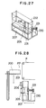
- Figure 27 shows a construction in which a line head 200 as shown in Figure 25 is scanned by a rotatable porous member 205.
- the porous member 205 is attached to two wires 232 by a fastening means 231, and by driving the wires 232 by a motor 220 and a group of gears 221, the rotatable porous member 205 performs the rubbing operation along the line head 200.
- Figure 28 is a schematic side view showing a full line type ink jet recording apparatus according to the present embodiment.
- the recording head 200 effects recording while remaining stationary at a position PP (recording position) opposed to a recording medium P.
- a support member 201 carrying the recording head 200 thereon is moved from the recording position to a position opposed to a blade 206 for each page.
- the recovery device is then moved and the wires 232 are driven to thereby clean the discharge port surface by the blade 206.
- the recording head 200 When recording is to be resumed after a long downtime or the like, the recording head 200 is moved by a rubbing means switch, not shown, from the capping position by a cap 207 to a position at which it can bear against the rotatable porous member 205 as the rubbing means, and the ink film on the discharge port surface is removed by the aforedescribed operation.
- a motor 220 for driving the blade 206 and the porous member 205 is common, and by moving the recording head to a position opposed to each of them, cleaning corresponding to each of them is effected.
- the blade, the rubbing means and the cap are arranged in the named order from the recording position, and the interruption time of the recording operation can be shortened and efficient cleaning can be accomplished.
- the cap and the rubbing means may be reversed in arrangement.
- Figure 29 is a schematic view showing an ink jet recording apparatus according to a ninth embodiment of the present invention.
- This embodiment is basically similar in construction to the first embodiment, and the difference between the two embodiments is that the ink film is removed by the rubbing means in conformity with the temperature of the recording head 5 detected by a temperature sensor 91 for detecting the temperature of the recording head.
- the ink film is created by desiccation of the ink adhering to the discharge port surface and therefore, as previously described, it is ready to be created when the downtime of recording lasts long.
- the recording head is pre-heated by heating means or the like, not shown, so that the viscosity of the ink in the discharge ports (in the recording head 5) may not become great.
- pre-heating is so effected ruing the downtime of recording
- the desiccation of the discharge port is prevented by capping, the ink on the discharge port surface is dried and creates an ink film.
- the discharge port surface is cleaned by the rubbing means to thereby remove the ink film.
- FIG. 30 is a flow chart showing the cleaning operation by the present embodiment.
- the recording head 5 stands by at the home position.
- the recording head 5 is moved to the recording area and effects recording (step S103).
- cleaning is effected by the blade 10 for a predetermined time at each recording of a predetermined number of lines.
- the downtime is measured, but even if the downtime does not amount to a predetermined time, when the temperature of the recording head 5 reaches a predetermined value or more (step S105), the discharge port surface is cleaned by the rubbing means to thereby remove the ink film (step S106).
- the timer is reset, and return is made to step S102.
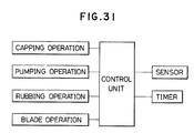
- Figure 31 is a block diagram showing the essential portions of a control system according to the present embodiment. As in the aforedescribed embodiments, design may be made such that the rubbing means is moved in operative association with the drive means for effecting capping.
- the present embodiment it becomes possible to effect the cleaning by the rubbing means which corresponds to the period of creation of the ink film, and the discharge port surface can be more efficiently kept in a good condition.
- FIG. 32 shows a construction in which the rotatable porous member 11 is dropped onto the block shaft 11E. Further, in this case, the joint between the rotatable porous member 11 and the ink cartridge 102 is such that as shown in Figure 33, the rotatable porous member 11 is held on a split pin 102b provided on the ink cartridge 102. That is, since the rubbing mechanism is also interchanged without fail during the interchange of the ink cartridge, the quality of the porous member is always maintained at a predetermined level or higher, and the occurrence of the non-discharge and the printing twist which would otherwise result from the deterioration of the porous member can be completely prevented.
- the discharge port surface of the recording head is cleaned by effecting the cleaning by the blade and the cleaning comprising rubbing the discharge port surface by the porous member, as the ink recovery operation, and the elimination of the printing twist in which the shooting point of the ink becomes irregular can be accomplished, and since a series of recovery sequences including the rubbing operation for the recording head are effected, stable discharge can be obtained without requiring any special operation. That is, by the means capable of effectively removing the ink drops, the water drops, the dust, the ink film etc. adhering to the vicinity of the discharge ports corresponding to the natures thereof, the removing operation can be accomplished correspondingly to the creation of them.
- the ink-repellent property of the surroundings of the discharge ports can be kept good and clean images formed by the ink can be obtained.
Abstract
Description
- This invention relates to an ink discharge recording device in an ink jet recording apparatus, and in particular to an ink discharge recovery device provided with cleaning means for cleaning the discharge port surface of a recording head.
- With an ink jet recording apparatus, it has sometimes been the case that in addition to the entry of air into a recording head and the adherence of paper powder and dust or viscosity-increased ink to the surroundings of the orifice of the recording head (the vicinity of an opening for discharging ink therethrough), unsatisfactory discharge such as non-discharge of the ink or the deviation of the direction of discharge is caused by the collection of the ink around the orifice.
- So, a means of solution such as the provision of means for removing these foreign materials which cause the unsatisfactory discharge has been adopted.
- In an ink jet recording apparatus, as means for preventing the ink discharge ports from clogging due to the increase in viscosity of ink caused by evaporation of the ink solvent or to the adherence of dust or the creation of bubbles, there is a construction as described, for example, in U.S. Patent No. 4,045,802 and U.S. Patent No. 4,603,931, wherein the ink discharge port surface of the recording head is covered with a cap to thereby shield the ink discharge port surface from the atmosphere and keep the discharge ports in a good condition, and a construction in which a discharge recovery device for causing ink to be discharged by a suction pump or the like is provided.
- Such a capping operation and such a discharge recovery operation are usually effected when a carriage is at its home position.
- Also, as a construction for removing ink and dust present near the discharge port, there is a construction as described in U.S. Patent No. 4,112,435, U.S. Patent No. 4,364,065 and Japanese Laid-Open Patent Application No. 58-94472 wherein as cleaning means, a flexible blade formed of rubber or like material is used to wipe the front face of the recording head (the surroundings of the discharge ports) (this will hereinafter be referred to as prior art ①). As the cleaning means, besides the above-mentioned one, there is a construction as described, for example, in U.S. Patent No. 4,306,245 wherein a brush and an ink absorbing member are slidden around the discharge ports (this will hereinafter be referred to as prior art ②). Further, there is a construction as described in Japanese Laid-Open Patent Application No. 59-83664 wherein the surroundings of the discharge ports are first wetted by sponge impregnated with water and then are wiped by a blade (this will hereinafter be referred to as prior art ③).
- However, it has been found from the numerous experiments carried out by the inventors that according to the above-described prior arts, ① - ③, recovery from unsatisfactory ink discharge is not fully accomplished in somecases and there is the necessity of improvement.
- In the case of prior art ①). liquid drops of relatively low viscosity such as ink drops adhering to the surroundings of the discharge ports and dewdrops formed on the surroundings of the discharge ports by the rise of the humidity in the apparatus can be removed by the discharge recovery operation using suction or the like. However, when an attempt is made to resume recording after recording has been ceased or stopped for a long time, the occurrence of non-discharge is eliminated by the discharge recovery device, but the direction of flight of ink deviates and thus, it has become impossible to cause ink droplets to adhere to a accurate positions on the surface of a recoridng medium and images formed thereon have sometimes been disturbed.
- In the case of
prior art ②, cleaning is repetitively effected at the home position and therefore, the stain or fluffing of the surface of the absorbing member attributable to the durability of the absorbing member causes foreign materials to adhere to the surroundings of the discharge ports, and this has sometimes resulted in unsatisfactory ink discharge. - In the case of
prior art ③, the sponge retains water content therein and therefore, the rise of the humidity in the apparatus is expedited and the total amount of water drops adhering to the surroundings of the discharge ports due to dew formation is increased, and this has increased the wiping operation by the blade and thus, this could not be a radical improvement. - So, the inventors have carried out recording tests under all conditions while observing the surroundings of the discharge ports of the recording head and have deeply sought after the causes of the occurrence of unsatisfactory ink discharge.
- As a result, it has been found that unsatisfactory discharge is attributable to the fact that the state of the ink adhering to the surroundings of the discharge ports OF changes as shown in Figures lA - ID of the accompanying drawings. If, as shown in Figures lA and lB, ink adheres as drops ID to the surroundings of the discharge ports OF, like dew, and is dried up, the ink assumes a state of very thin film ID′ on the surroundings of the discharge ports OF as shown in Figures 1C and 1D.
- Such an ink film ID′ has often been created when non-recording has lasted long. Heretofore, it has been known that unsatisfactory discharge occurs when recording is resumed after a long downtime of recording, but the cause thereof has been regarded as being attributable to an increase in the viscosity of ink or entry of air into ink. Certainly, most of the causes of non-discharge are the clogging resulting from an increase in the viscosity of ink and entry of air, but nobody has been aware that the cause of the deviation of the direction of ink discharge is attributable to the film of ink as noted above. Further, such a film has reduced the ink-repellent property of the discharge port surface and has induced a state in which ink is ready to adhere.
- In view of the above-noted fact, the inventors have studied, through the numerous experiments repetitively carried out by them, what is the construction of an ink jet recording apparatus in which the causes of unsatisfactory discharge can be eliminated most effectively and good recorded image can be obtained.
- As a result, it has been found that as the cleaning means for the discharge port (orifice) surface of the ink jet recording apparatus, it is still preferable from the viewpoints of the effect of wiping and the problem of the durability of the cleaning means to remove ink drops, pools of ink and formed dew on the discharge port (orifice) portion by the aforementioned flexible blade. In an apparatus provided with a heating and fixating heater for expediting the fixation of ink, particularly, the ink adhering as a recorded image to the recording medium, the probability with which dew is formed by the evaporation of the water content of the ink becomes high and the role of the blade is very great. However, if ink drops or pools of ink adhere to the surroundings of the discharge ports for a long time and form very thin film or the like on the surroundings of the discharge ports, the direction of discharge is made unstable by the film even if apparently pools of ink are eliminated, and in addition, the ink-repellent property of the discharge port surface is reduced and pools of ink become ready to be created and thus, discharge twist becomes ready to occur. Such ink film could not be fully removed by the cleaning by the blade as previously described.
- The present invention has been made in view of the above-noted problems. It is an object of the present invention to provide an ink jet recording apparatus in which ink drops, water drops, dust, etc. adhering to the vicinity of discharge ports can be remove and a film caused by the ink adhering thereto can also be removed.
- It is another object of the present invention to provide an ink jet recording apparatus in which unsatisfactory ink discharge can be prevented from occurring due to deterioration of a member for cleaning discharge ports.
- It is still another object of the present invention to provide an ink jet recording apparatus in which optimum cleaning can be effected in conformity with the state of foreign materials adhering to the vicinity of discharge ports to thereby prevent unsatisfactory discharge.
- It is yet still another object of the present invention to provide an ink jet recording apparatus in which the effect of removing a film by a rubbing member can be kept good.
- It is a further object of the present invention to provide a method of cleaning the vicinity of the discharge ports of an ink jet recording apparatus, characterized in that cleaning comprising wiping the vicinity of said discharge ports by a blade with a certain contact surface with respect to the vicinity of said discharge ports and cleaning comprising rubbing the vicinity of said discharge ports by rubbing means with a contact surface larger than said contact surface are effected independently of each other.
- It is still a further object of the present invention to provide an ink jet recording apparatus in which cleaning conforming to the state of ink can be accomplished by said method to thereby prevent unsatisfactory ink discharge.
- It is yet still a further object of the present invention to provide an ink jet recording apparatus having a recording head having discharge ports for discharge ink therethrough, blade means for wriping the vicinity of said discharge ports with a certain contact surface with respect to the vicinity of said discharge ports, rubbing means for rubbing the vicinity of said discharge ports with a contact surface larger than said contact surface, and control means for driving the wiping operation by said blade means and the rubbing operation by said rubbing means independently of each other.
- It is another object of the present invention to provide an ink jet recording apparatus having a carriage for scanning a recording head having discharge ports for discharging ink therethrough relative to a recording medium, and heating means for heating said recording medium, characterized by blade means provided outside the recording area for wiping the vicinity of said discharge ports on the basis of a predetermined sequence during the recording operation, rubbing means differing from said blade means and provided at a position outside the recording area whereat it can contact with said recording head, and means for moving said carriage to the vicinity of a position at which it can contact with said rubbing means, said means producing a command for cleaning the vicinity of said discharge ports by said rubbing means when a predetermined signal is input to said means.
- It is still another object of the present invention to provide an ink cartridge removably mounted with respect to an ink jet recording apparatus having a cleaning member for cleaning the vicinity of discharge ports for discharging the ink of a recording head therethrough, and containing ink to be supplied to said head, characterized by means for connecting said cleaning member and said cartridge together.
- It is yet still another object of the present invention to provide an ink jet recording apparatus provided an ink jet recording apparatus provided with an ink cartridge in which an interchangeable member such as a cleaning member is connected by said construction, whereby the maintenance work is simplified.
- It is another object of the present invention to provide an ink jet recording apparatus which enables the user to readily know the period of interchange of a cleaning member.
-
- Figures 1A - 1D are schematic views showing the state of the discharge port surface of a recording head.
- Figures 2A - 2C are a schematic plan view, a schematic perspective view and a schematic perspective view, respectively, showing the essential portions of an ink jet recording apparatus according to the present invention.
- Figure 3 is a schematic perspective view of an ink discharge recovery device in Figure 2.
- Figure 4 is a schematic front view corresponding to Figure 3.
- Figure 5 is a schematic side view corresponding to Figure 3.
- Figure 6 is a schematic fragmentary enlarged elevational view of a worm wheel cam in Figure 3.
- Figure 7 is a schematic fragmentary enlarged plan view of a rubbing mechanism in Figure 3.
- Figure 8 is a flow chart showing the operation procedure of the rubbing mechanism of an ink jet recording apparatus according to the present invention.
- Figure 9 is a flow chart showing a series of operation procedures of the cleaning operation according to the present invention.
- Figures 10 and 11 are schematic perspective views showing the essential portions of a rubbing mechanism for the orifice surface of a line print type recording apparatus.
- Figure 12 is a schematic fragmentary enlarged plan view of a fourth embodiment of the rubbing mechanism of Figure 7.
- Figure 13 is a schematic fragmentary perspective view of the rubbing mechanism of the discharge recovery device of an ink jet recording apparatus according to a fifth embodiment of the present invention.
- Figure 14 is a block diagram of an embodiment of the present invention.
- Figure 15 is a block diagram of another embodiment of the present invention.
- Figure 16 is a schematic plan view showing the essential portions of an ink jet recording apparatus according to an embodiment of the present invention.
- Figures 17, 18 and 19 are a schematic perspective view, a schematic front view and a schematic side view, respectively, of an ink discharge recovery device in Figure 16.
- Figure 20 is a schematic view of a pump during mechanism in the present invention.
- Figure 21 is a schematic cross-sectional view of a rubbing mechanism portion in the present invention.
- Figure 22 is a schematic perspective view of the rubbing mechanism portion in the present invention.
- Figure 23 is a schematic perspective view showing an ink cartridge according to an embodiment of the present invention as it is made integral with the rubbing mechanism portion.
- Figure 24 is a flow chart showing a series of cleaning operation procedures according to the present invention.
- Figure 25 is a schematic perspective view showing the rubbing mechanism portion in a full line head construction.
- Figure 26 is a schematic perspective view showing the porous member shown in Figure 25 as it is made integral with an ink cartridge.
- Figures 27 and 28 are a schematic perspective view of the rubbing mechanism in the present invention and a schematic view of a full line type ink jet recording apparatus, respectively.
- Figure 29 is a schematic view showing an embodiment of the present invention.
- Figure 30 is a flow chart showing a series of cleaning operation procedures according to the present invention.
- Figure 31 is a block diagram of the present invention.
- Figure 32 is a schematic top plan view showing a construction in which a rotatable porous member is made interchangeable.
- Figure 33 is a schematic perspective view showing the rotatable porous member shown in Figure 32 as it is made integral with an ink cartridge.
- The present invention will hereinafter be described specifically with reference to the drawings, but the present invention is not restricted to embodiments which will hereinafter be described.
- That is, the present invention may be of any construction which can achieve the objects of the invention, and may of course permit combinations of constituents in the embodiments which will hereinafter be described, the timing of the cleaning operation and the sequence, as well as may be one which effects sequence control comprising a combination of further constituents.
- Figures 2A - 2C are a schematic plan view, a schematic perspective view and a schematic perspective view, respectively, showing the essential portions of an ink jet recording apparatus according to the present invention.
- Referring to Figure 2A, a
guide shaft 3 is installed forwardly ofpaper 2 as a recording medium backed up by aplaten 1, and an inkjet recording head 5 is carried on acarriage 4 movable along theguide shaft 3. Heating means 1′ such as a fixating heater is provided on a discharge route for thepaper 2 after recording. An electro-thermal converting member, not shown, as energy generating means for generating energy utilized to discharge ink is provided in therecording head 5, and by causing heat energy to act on the ink, the ink is discharged. Such a recording head is preferably used for its numerous merits, but may be one using a piezo element or the like. Also, the recording head may be of a construction integrally having an ink tank for containing ink therein, or may be a full line type head in which a number of discharge ports are disposed widthwisely of the recording medium. The discharge port surface of the above-described recording head is subjected, for example, to ink-repellent surface treatment. - A discharge recovery device (of the pump suction type in the illustrated embodiment) 6 for the
recording head 5 is provided at the home position HP of thecarriage 4. This discharge recovery device is provided with capping means 7 having acap 30 driven forward and backward relative to therecording head 5 and covering the front face (the orifice portion) of the recording head at the forwardly moved position thereof, and apump 9 for sucking the ink from the orifices (the ink discharge ports) through the capping means 7. The operation of this recovery device is effected by the input or the like of a key switch. not shown. - A
flexible blade 10 for wiping the vicinity of the discharge ports (for example, the discharge port surface) of therecording head 5 is mounted on a side of thedischarge recovery device 6. - In the present invention, the blade refers to a member which makes substantially line contact with the discharge port surface, that is, whose area of contact CA is small (see Figure 2B), and rubbing means refers to a means whose area of contact CA is great (see Figure 2C).
- A rubbing
mechanism 11 movable forward and backward with the capping means 7 is provided on a side of the capping means 7. - This rubbing
mechanism 11 is means for rubbing the vicinity of the discharge ports (for example, the discharge port surface) of therecording head 5, and has a greater area of contact with the discharge port surface than the aforementioned blade. When therecording head 5 has come off the home position HP by the drive control of thecarriage 4 and has come to a position indicated by a dot-and-dash line in Figure 2, the rubbing member is driven forward with the capping means 7 to bear against the orifice portion and thecarriage 4 is moved by a predetermined distance, whereby the orifice surface is rubbed by the rubbing member. - Thus, the rubbing operation of the rubbing
mechanism 11 may be accomplished by the cap operation and the carriage operation. - Figure 3 is a schematic perspective view of the
discharge recovery device 6, Figure 4 is a schematic front view corresponding to Figure 3, Figure 5 is a schematic side view corresponding to Figure 3, and Figure 6 is a schematic elevational view of a worm wheel portion forming the drive mechanism in Figure 3. - Referring to Figures 3-6, the
pump 9 is mounted on aframe 15, and aworm wheel 12 rides on thepiston 9A (Figure 6) of thepump 9, and aworm wheel shaft 12A integral with theworm wheel 12 is supported by alid 16. - When a
worm 14A (Figure 6) integral with aworm wheel 14 is rotatively driven, theworm wheel 12 which is in meshing engagement with theworm 14A is rotated. - In this case, the
worm wheel 12 is formed with aworm wheel cam 13, and when theworm wheel 12 is rotated, theworm wheel cam 13 comes into abutment against a fixedcam 13A (Figure 6), whereby theworm wheel 12 is moved downward and thepiston 9A of thepump 9 is depressed. - The
pump 9 is driven by the depression of thispiston 9A and generates a negative suction force lower than the atmospheric pressure. - The return of the
piston 9A (the discontinuance of the operation of the pump 9) is accomplished by a spring (a return spring), not shown, in thepump 9. - The forward and backward movement of the capping means 7 with respect to the
recording head 5 is accomplished by the engagement between the inner surface cam (another cam surface, not shown) of theworm wheel cam 13 and the capping means. - As previously described, the
cap 30 formed, for example, of silicone, butyl chloride or the like adapted to be sealingly urged against the orifice surface is provided on the front face of the capping means. - The
blade 10 is controlled by a combination of the forward and reverse rotation of thecam 13, a blade stop lever and the carriage operation so that it is moved forward by a predetermined amount when the capping means 7 is brought into its opened condition by rotation of thecam 13. Alternatively, theblade 10 may be fixed at its forwardly moved position. - Figure 7 is a partial plan view showing the assembled state of the rubbing
mechanism 11. - Referring to Figure 7, the rubbing
mechanism 11 comprises ablock 11B supported on abase member 7A integral with the capping means 7 for movement back and forth, and a rubbingmember 11C attached to theblock 11B with a plate-like porous material interposed in a U-shape therebetween, said rubbingmember 11C being assembled in such a manner that the current surface portion thereof is protruded by a predetermined amount toward the recording head side by acompression spring 11A mounted between theblock 11B and thebase member 7A. - The anti-slippage of the
block 11B from thebase member 7A is accomplished by asnap ring 11D. - The material forming the rubbing
member 11C may preferably be a porous material, and more preferably be a material having more or less soft texture and a water-absorbing property, such as urethane, polyvinyl alcohol (PVA), polyethylene (PE), polyvinyl formal, polypropylene or polyurethane, and unwoven fabric or the like is also usable as the rubbing member. - Figure 8 is a flow chart of the operation procedure when the rubbing operation of the orifice portion of the
recording head 5 is effected by the above-described rubbingmechanism 11. - In Figure 8, at step F1, the
recording head 5 is first moved to the home position HP, and the capping means 7 is kept as it is or is once closed, whereafter it is opened (step F2). - Next, at step F3, the
carriage 4 is moved to the right as viewed in Figure 1 by a predetermined ith the capping means 7 opened, and is set in a position wherein the rubbingmember 11C can bear against the orifice portion of therecording head 5. - Then, at step F4, the capping means 7 is moved forward to a point corresponding to the closed position and the rubbing member llC of a porous material is urged against the orifice portion by the
spring 11A. - Then, at step F5, the
carriage 4 is further moved to the right as viewed in Figure 2 with the rubbingmember 11C urged against the orifice portion, and the rubbingmember 11C is slidden while rubbing the orifice surface. Thereby, a very thin adhering film or the like produced by the desiccation of pools of ink on the orifice surface is removed. - By the film of ink being thus removed, the wetting property of the orifice surface can be maintained constant and stable ink discharge can be realized.
- After the orifice surface has been rubbed, at step F6, the capping means 7 is moved backward, and at step F7, the
recording head 5 is returned to the home position HP. - Also, the ink
discharge recovery device 6 has various recovering functions. - That is, the discharge recovery device has various recovering functions such as the discharge recovery for effecting the charge of ink into the ink supply system, the
recording head 5 and a sub-tank provided between the recording head and a main tank containing the ink therein and the discharge of ink increased in viscosity and bubbles, and the recovery for dissolving the ink increased in viscosity and solidified ink by a three-way valve mechanism 20 (Figure 5) for directing the ink from the sub-tank in the ink supply system to the cap and a vent mechanism 21 (Figure 5). - By suitably combining these various recovering functions, the cleaning by the blade and the cleaning by the rubbing means, a control system is constructed so that always stable ink discharge can be easily and reliably obtained correspondingly to various conditions of use.
- The recovery operation including the above-described rubbing operation will hereinafter be described in detail.
- Figure 9 is a flow chart showing the sequence control operation of the recovery operation. When at step S1, the power switch of the ink jet recording apparatus is closed, the
pump 9 is driven and the ink is sucked from the discharge port through thecap 30 and the elimination of the clogging of the discharge ports, the discharge of bubbles, etc. are effected (step S2). Next, at step S3, capping is released and the above-described rubbing operation is performed, whereafter capping is again effected at the home position and the apparatus becomes ready for the recording operation (step S4). When at step S5, a print command comes upon inputting of a recording signal, capping is released and recording is effected (step S6). When a predetermined time (e.g., 10 to 20 sec.) passes after recording has been started (step S7), recording is interrupted and the recording head is moved toward the home position. At this time, theblade 10 is moved forward toward the discharge port surface of therecording head 5. Therecording head 5 is moved from the recording area side to the home position side relative to theblade 10 thus moved forward, whereby the recording head is wiped (step S8). Thereafter, at the home position, predischarge of the ink in thecap 30 is effected (step S9), and therecording head 5 continues to be moved to the recording area, thus resuming recording. - In the ink jet recording apparatus, during the recording operation, the internal humidity rises due to the discharged ink and the heating of the recording medium by the heater for fixation, and ink drops and water drops resulting from dew formation are liable to adhere to the discharge port surface, and it is desirable to clean the discharge port surface by the blade at predetermined time intervals. However, it is difficult for the ink film caused by the desiccation of the discharge port surface to be produced during the recording operation. This occurs chiefly during a long downtime of recording.
- Accordingly, the cleaning of the discharge port surface by the rubbing means is effected on the basis of a predetermined input signal independently of the cleaning by the blade. That is, the cleaning by the rubbing means is effected only after a long downtime of recording such as the time of power-ON, whereby deterioration of the rubbing means is prevented and efficient release of unsatisfactory discharge conforming to the objects to be removed (ink drops and ink film) can be accomplished.
- As regards the timing of the cleaning by the rubbing means, for example, the aforedescribed rubbing function for the orifice surface of the
recording head 5 may be omitted in the automatic recovery during the power-ON, and various control sequences may also be designed so that as by effecting the cleaning by the rubbing means during the recovery operation in conformity with a signal produced by the depression of a key switch for effecting a recovery operation differing from the ordinary recovery during the unpacking of the recording apparatus or after a long downtime of the apparatus, the function of the rubbing means is kept good and the time for the recovery operation is made necessary minimum and the amount of ink consumed is minimized. - Further, the rubbing
mechanism 11 is of a structure supported by a spring and having back-lash relative to the capping means 7, and is designed such that when it bears against therecording head 5, it is moved backward by spring displacement and the bearing surface thereof becomes proper. - The control or the like of the recovery mechanism such as the capping means 7 and the
suction pump 9 and of the cleaning means is executed by detecting the position of the cam (the worm wheel cam) 13 by the contact 17 (Figure 4) of a limit switch or the like, setting the driving pulse and controlling the angle of rotation of thecam 13. The aforedescribed rubbing operation for the orifice portion is a part of the recovery sequence, and various combinations are possible such as effecting the rubbing operation after predischarge is effected from therecording head 5 to the rubbing member (porous material) 11C and effecting the rubbing operation before or after the sucking operation by thepump 9. - Also, in the illustrated embodiment, the rubbing
means 11 is operatively associated with the capping means 7, but alternatively, these may be individually controlled without being operatively associated with each other. - Further. the present invention is not restricted to a serial type recording apparatus in which the
recording head 5 is reciprocally moved to the left and right by thecarriage 4, but may also be applied to a line print type recording apparatus. - Figure 10 is a schematic perspective view showing the essential portions of a rubbing mechanism for the line head of a line print type ink jet recording apparatus.
- More particularly, Figure 10 shows an ink jet recovery
device using arms drive source 51 such as a solenoid and areturn spring 52 and a long rotatable roll type rubbing member (porous material) 54 to rub the front surface of a line head (ink jet head) 55, i.e., the surface in whichorifices 56 are arranged. - In the structure of Figure 10, the
porous material 54 is made into a rotatable member and therefore, abrasion can be reduced. - Figure 11 shows a rubbing mechanism in which a roll type rubbing member (porous material) 62 rotatable about a vertical axis is mounted between two upper and
lower wires wires member 62 while the rubbingmember 62 bears against the orifice portion in the front surface of the line head (not shown). - Figure 12 is a plan view showing the essential portions of still another embodiment of the present invention.
- This embodiment is such that a
block shaft 11E perpendicular to ablock 11B supported on thebase plate 7A of the capping means 7 is provided and a roll-likerotatably rubbing member 11C of porous material is rotatably and interchangeably mounted in such a manner as to be dropped onto theblock shaft 11E from above. - The other portions and sequence of the present embodiment are substantially the same as those of the aforedescribed first embodiment.
- Figure 13 shows another example of the structure of the rubbing
mechanism 11 in which the rubbingmember 11C of porous material is formed integrally with therubber cap 30 fitted to the front face of the capping means 7. Acap clip portion 30A which is in intimate contact with the circumference of the orifice portion of therecording head 5 is formed around the cap portion of therubber cap 30. - In the example shown in Figure 13, the rubbing
member 11C is formed of a soft porous material protruding in a semi-cylindrical shape sideways of thecap clip portion 30A on the front face of therubber cap 30, as shown. - According to the rubbing mechanism of Figure 13, the resiliency of the
cap spring 7B (Figures 5 and 13) of the capping means 7 and the elasticity of therubber cap 30 itself can be utilized to cause the rubbingmember 11C to bear against the orifice portion with a desired pressure force and therefore, the rubbing member mounting mechanism comprising thespring 11A, theblock 11B and thesnap ring 11D shown in Figure 7 can be eliminated to thereby reduce the number of parts of the rubbingmechanism 11 and simplify the structure thereof. - According to the above-described first to fifth embodiments, discretely from the operation of the blade, the
mechanism 11 operatively associated with the capping means 7 of the inkdischarge recovery device 6 and rubbing the orifice surface of therecording head 5 as a part of a series of recovery sequences is provided and the recovery operation is performed by the utilization of the rubbing operation of the rubbingmechanism 11 and the operation of the carriage and therefore, pools of ink can be removed and an ink film produced by the desiccation or the like of the pools of ink can also be removed easily and reliably by a simple control circuit and a simple drive system, and it has become possible to keep the wetting property of the orifice portion of the recording head constant and realize stable ink discharge. - Also, during the ink recovery operation, the orifice portion of the
recording head 5 can be rubbed by the rubbing member (porous material) 11C, 54, 62 and therefore, the wetting property (the ink-repellent property) of the orifice portion can always be easily maintained constant, and it has become possible to eliminate any printing twist which makes the shooting point of the ink irregular. - Further, the series of recovery sequences are effected with the rubbing operation for the
recording head 5 and therefore, any special operation has become unnecessary. - Figure 14 is a block diagram for effecting the rubbing operation.
- Also, discretely from what has been described above, as shown in the block diagram of Figure 15, the rubbing operation can be accomplished by another drive system without the utilization of the carriage operation.
- The present invention can also be carried out by other various suitable sequences than the above-described sequences.
- Figure 16 shows the construction of the essential portions of an ink jet recording apparatus according to a sixth embodiment of the present invention. The basic construction of this embodiment is similar to that of the previously described embodiment, but it will be described again. In Figure 16, the reference numeral l designates a platen forming a recording surface by a cylindrical member, and the
reference numeral 2 denotes recording paper twined around theplaten 1 and having its recording position thereof moved by rotation of theplaten 1. - The
reference numeral 3 designates a guide shaft, thereference numeral 4 denotes a carriage, and thereference numeral 5 designates a recording head. Thecarriage 4 is moved along theguide shaft 3 by the drive of a motor, not shown, and with this movement, therecording head 5 carried on thecarriage 4 records images on therecording paper 2. - HP indicates the home position of the
carriage 4, and at the home position HP, an inkdischarge recovery device 6 is disposed in such a manner as to be opposed to the discharge port surface of therecording head 5. The inkdischarge recovery device 6 is comprised of capping means 7 movable forward and backward in opposed relationship with therecording head 5 and hermetically sealing the discharge port surface of therecording head 5 in the forwardly moved position thereof, and apump 9 driven by a discharge recovering operation lever, not shown, and sucking ink from the ink discharge ports through the capping means 7. - On a side, i.e., the right side as viewed in Figure 16, of the capping means 7, there is provided a
flexible blade 10 for wiping the ink discharge port surface of therecording head 5. Thereference numeral 11 designates a rubbing mechanism disposed on a portion of the surface of the capping means 7 which is opposed to therecording head 5. The rubbing mechanism moves with forward and backward movement of the capping means 7. - Figures 17, 18 and 19 are a schematic perspective view, a schematic front view and a schematic side view, respectively, of the ink discharge recovery device. Figure 20 is a schematic side view showing the details of a pump driving mechanism in the ink discharge recovery device.
- In these figures, the
reference numeral 15 designates a frame forming the bottom plate of the inkdischarge recovery device 6, thereference character 9A denotes the piston of apump 9, thereference numeral 12 designates a worm wheel, thereference character 12A denotes a worm wheel shaft, and thereference numeral 16 designates a lid. Thepump 9 is mounted on theframe 15, and thepiston 9A and theworm wheel 12 are connected together, and theworm wheel shaft 12A is supported on thelid 16 forming a part of theframe 15. Theworm wheel 12 and thepiston 9A are integral with each other and are vertically movable along theworm wheel shaft 12A, and are biased upwardly by a spring or the like, not shown, in thepump 9. - The
reference numeral 13 designates a cam mechanism engaged with the capping means 7, and thiscam mechanism 13 is driven by a motor, not shown. Thereby, forward and backward movement of the capping means 7 is accomplished. Also, theblade 10 is driven by the cam of thecam mechanism 13, and by appropriately controlling the rotation thereof, a position opposed to the capping means 7 is defined. - In Figure 20, the reference numeral 12D designates a worm for transmitting to the
worm wheel 12 the drive force transmitted through theworm shaft 14 shown in Figure 17, thereby rotating theworm wheel 12. The reference character 12B denotes a worm wheel cam mounted on theworm wheel 12, and thereference character 13A designates a fixed cam fixed to thelid 16. - By the engagement between the worm wheel cam 12B and the fixed
cam 13A which results from the rotation of theworm wheel 12, theworm wheel 12 is biased and moved downward. Thereby, thepiston 9A effects its pressing action in the cylinder of thepump 9 and acommunication valve lever 20A is depressed to effect appropriate opening and closing of acommunication valve 20. When released from the bias by theworm wheel 12, thecommunication valve lever 20A restores its original position by the force of a spring or the like, like thepiston 9A does. By the series of operations of thepiston 9A and thecommunication valve lever 20A, the discharge recovery process of sucking the ink increased in viscosity in the nozzle and near the ink discharge ports with thecap opening portion 30 of the capping means 7 shown in Figures 17, etc. being brought into intimate contact with the ink discharge port surface is accomplished. - Figure 21 is a top plan view showing the details of the rubbing mechanism. In Figure 21, the
reference character 11B designates a block rotatably mounted on a shaft disposed at a predetermined location in the capping means 7. Thereference character 11C denotes a porous member mounted in a U-shape along theblock 11B. Thisporous member 11C, as in the aforedescribed embodiments, may preferably be formed of soft texture comprising a material such as urethane, PVA or PE. Thereference character 11E designates a base forming the body of the rubbingmeans 11, and thereference character 11A denotes a leaf spring attached to thebase 11E to bias theblock 11B by a predetermined amount. - Figure 22 is a perspective view showing the details off a holding member for the
porous member 11C. L-shapedgrooves 11H are formed at two locations in theblock 11B, and theporous member 11C is embedded in a U-shape along these grooves. As a result, theporous member 11C is exposed at a portion of theblock 11B, and the discharge port surface of therecording head 5 is rubbed by this exposed portion. Leaf springs 11A are disposed at two locations on that side of the block 1B which is opposite to the side on which theporous member 11C is exposed, and theleaf springs 11A are brought into contact with thebase 11E shown in Figure 21. Adowel 11F is also slidably engaged with a hole formed in thebase 11E, and when rubbing the discharge port surface, theblock 11B is moved in the driection of arrow G indicated in Figure 21 while being subjected to the bias of theleaf springs 11A. - Now, among the cleaning members, the life of the porous member 11lC of the rubbing
means 11 is considerably short as compared with the life of the head and therefore, if it is used beyond its life, the porous surface will become coarse and flully and the rubbing effect will become incomplete. So, according to the experiment carried by the inventors, the life of thisporous member 11C substantially corresponds to the time during which the ink in the ink cartridge is consumed, and if theporous member 11C is interchanged during the interchange of the ink cartridge, the rubbing effect can always be maintained and it will be possible to prevent printing twist or the like and thereby prevent deterioration of the quality of recorded images. - Therefore, as a means for ensuring the user to interchange the
porous member 11C during the interchange of the ink cartridge, it has been conceived to make the rubbingmechanism 11 including theporous member 11C integral with the ink cartridge. - That is. as shown in Figure 23,
ink cartridge holders 101 are attached to thebase 100 of the recording apparatus, and guidegrooves 101a for theink cartridge 102 are formed in theholders 101. Theink cartridge 102 is pushed in along theguide grooves 101a by a predetermined stroke in the direction of arrow. - The rubbing
mechanism 11 is made integral with the upper portion of theink cartridge 102 and therefore, the rubbingmechanism 11 will strike against thebase 100 of the recording apparatus and theink cartridge 102 will become uninsertable. So, by breaking the rubbingmechanism 11 at itsroot portion 11J, the rubbingmechanism 11 and theink cartridge 102 are separated from each other and here, for the first time, the insertion of theink cartridge 102 becomes possible. The separated rubbingmechanism 11 is interchanged with the old rubbing mechanism by the user, and the problem of the deteriorated quality of recording caused by forgotten interchange is solved. - The sequence of the recovery operation in the present embodiment will now be described in detail with reference to the flow chart of Figure 24.
- When at step S11, the power switch is closed, the pump is driven and the ink is sucked from the discharge ports (step S12), whereafter the recording standby condition is brought about, but if at this time, at step S13, there are the input of a switch provided in the apparatus and the inputting of a rubbing means driving signal from a host computer, the rubbing operation is performed as in the aforedescribed first embodiment, and the ink film is removed (step S14).
- The recording head is again capped and enters the recording standby condition (step S15). When at step S16, a recording command is given by the inputting of a recording signal, the recording head is reciprocally moved in the recording area and discharges the ink to thereby accomplish recording (step S17). If at this time, recording of a predetermined number of lines is effected, the cleaning by the blade takes place to remove the ink drops or the like on the discharge port surface. The recording of a predetermined number of lines may be printing in one direction effected a plurality of times, or printing in both directions effected a plurality of times. Also, the cleaning switch of the rubbing means may be the same as the switch for effecting the suction recovery (PUMP ON) when the apparatus is in power-ON condition, and the rubbing operation and the suction recovery operation may be effected in association with each other.
- Figure 25 schematically shows the construction of a rubbing mechanism in the case of a line printer, and more particularly shows an example in which a long rotatable
porous member 103 corresponding to a recording head is caused to bear against the ink discharge port surface of aline head 122 by the operation of asolenoid 120 and aspring 121. The rotatableporous member 103 is removably mounted relative to asupport member 123. - Figure 26 shows a rotatable
porous member 103 which is made integral with anink cartridge 102 in the case of the construction shown in Figure 25. This rotatableporous member 103 is removably held by a holdingmember 102a integrally formed on theink cartridge 102. In this case, the holdingmember 102a remains in a convex shape after the rotatableporous member 103 is pulled out and therefore, a contrivance such as the provision of a groove permitting the escape thereof on the base 100 side of the recording apparatus is necessary. - Figure 27 shows a construction in which a
line head 200 as shown in Figure 25 is scanned by a rotatableporous member 205. In Figure 27, theporous member 205 is attached to twowires 232 by a fastening means 231, and by driving thewires 232 by amotor 220 and a group ofgears 221, the rotatableporous member 205 performs the rubbing operation along theline head 200. - Figure 28 is a schematic side view showing a full line type ink jet recording apparatus according to the present embodiment.
- During the recording operation, as shown, the
recording head 200 effects recording while remaining stationary at a position PP (recording position) opposed to a recording medium P. In a case where therecording head 200 effects the printing of a predetermined number of lines or in the case of a cut sheet, asupport member 201 carrying therecording head 200 thereon is moved from the recording position to a position opposed to ablade 206 for each page. The recovery device is then moved and thewires 232 are driven to thereby clean the discharge port surface by theblade 206. When recording is to be resumed after a long downtime or the like, therecording head 200 is moved by a rubbing means switch, not shown, from the capping position by acap 207 to a position at which it can bear against the rotatableporous member 205 as the rubbing means, and the ink film on the discharge port surface is removed by the aforedescribed operation. - A
motor 220 for driving theblade 206 and theporous member 205 is common, and by moving the recording head to a position opposed to each of them, cleaning corresponding to each of them is effected. - According to the above-described construction, even in an ink jet recording apparatus using a full line type recording head, the blade, the rubbing means and the cap are arranged in the named order from the recording position, and the interruption time of the recording operation can be shortened and efficient cleaning can be accomplished. (The cap and the rubbing means may be reversed in arrangement.)
- Figure 29 is a schematic view showing an ink jet recording apparatus according to a ninth embodiment of the present invention.
- This embodiment is basically similar in construction to the first embodiment, and the difference between the two embodiments is that the ink film is removed by the rubbing means in conformity with the temperature of the
recording head 5 detected by atemperature sensor 91 for detecting the temperature of the recording head. - The ink film is created by desiccation of the ink adhering to the discharge port surface and therefore, as previously described, it is ready to be created when the downtime of recording lasts long. During the downtime of recording, it is sometimes the case that the recording head is pre-heated by heating means or the like, not shown, so that the viscosity of the ink in the discharge ports (in the recording head 5) may not become great. When pre-heating is so effected ruing the downtime of recording, it is sometimes the case that although the desiccation of the discharge port is prevented by capping, the ink on the discharge port surface is dried and creates an ink film. In order to prevent this, in the present embodiment, when the temperature of the recording head is above a predetermined level and recording is not being effected, the discharge port surface is cleaned by the rubbing means to thereby remove the ink film.
- Figure 30 is a flow chart showing the cleaning operation by the present embodiment. At step S101, the
recording head 5 stands by at the home position. When at step S102, a recording command is given, therecording head 5 is moved to the recording area and effects recording (step S103). During the recording operation, as in the aforedescribed embodiment, cleaning is effected by theblade 10 for a predetermined time at each recording of a predetermined number of lines. At step S104, the downtime is measured, but even if the downtime does not amount to a predetermined time, when the temperature of therecording head 5 reaches a predetermined value or more (step S105), the discharge port surface is cleaned by the rubbing means to thereby remove the ink film (step S106). Thereafter, at step S107, the timer is reset, and return is made to step S102. - Figure 31 is a block diagram showing the essential portions of a control system according to the present embodiment. As in the aforedescribed embodiments, design may be made such that the rubbing means is moved in operative association with the drive means for effecting capping.
- As described above, according to the present embodiment, it becomes possible to effect the cleaning by the rubbing means which corresponds to the period of creation of the ink film, and the discharge port surface can be more efficiently kept in a good condition.
- This embodiment is a construction which corresponds to the aforedescribed fourth embodiment. Figure 32 shows a construction in which the rotatable
porous member 11 is dropped onto theblock shaft 11E. Further, in this case, the joint between the rotatableporous member 11 and theink cartridge 102 is such that as shown in Figure 33, the rotatableporous member 11 is held on a split pin 102b provided on theink cartridge 102. That is, since the rubbing mechanism is also interchanged without fail during the interchange of the ink cartridge, the quality of the porous member is always maintained at a predetermined level or higher, and the occurrence of the non-discharge and the printing twist which would otherwise result from the deterioration of the porous member can be completely prevented. - As described above, according to the present invention, the discharge port surface of the recording head is cleaned by effecting the cleaning by the blade and the cleaning comprising rubbing the discharge port surface by the porous member, as the ink recovery operation, and the elimination of the printing twist in which the shooting point of the ink becomes irregular can be accomplished, and since a series of recovery sequences including the rubbing operation for the recording head are effected, stable discharge can be obtained without requiring any special operation. That is, by the means capable of effectively removing the ink drops, the water drops, the dust, the ink film etc. adhering to the vicinity of the discharge ports corresponding to the natures thereof, the removing operation can be accomplished correspondingly to the creation of them.
- Accordingly without permitting any foreign material to adhere to the recording head, the ink-repellent property of the surroundings of the discharge ports can be kept good and clean images formed by the ink can be obtained.
Claims (31)
a recording head having discharge ports for discharging ink therethrough;
blade means for wiping the vicinity of said discharge ports with a certain contact surface with respect to the vicinity of said discharge ports;
rubbing means for rubbing the vicinity of said discharge ports with a contact surface larger than said contact surface; and
control means for driving the wiping operation by said blade means and the rubbing operation by said rubbing means independently of each other.
blade means provided outside the recording area for wiping the vicinity of said discharge ports on the basis of a predetermined sequence during the recording operation;
rubbing means differing from said blade means and provided at a position outside the recording area whereat it can contact with said recording head; and
means for moving said carriage to the vicinity of a position at which it can contact with said rubbing means, said means producing a command for cleaning the vicinity of said discharge ports by said rubbing means when a predetermined signal is input to said means.
Applications Claiming Priority (8)
| Application Number | Priority Date | Filing Date | Title |
|---|---|---|---|
| JP27503587 | 1987-10-30 | ||
| JP275035/87 | 1987-10-30 | ||
| JP27503487 | 1987-10-30 | ||
| JP275034/87 | 1987-10-30 | ||
| JP278175/87 | 1987-11-05 | ||
| JP27817587 | 1987-11-05 | ||
| JP253458/88 | 1988-10-07 | ||
| JP63253458A JP2626805B2 (en) | 1987-10-30 | 1988-10-07 | Ink jet recording device |
Publications (3)
| Publication Number | Publication Date |
|---|---|
| EP0314513A2 true EP0314513A2 (en) | 1989-05-03 |
| EP0314513A3 EP0314513A3 (en) | 1989-11-08 |
| EP0314513B1 EP0314513B1 (en) | 1993-07-14 |
Family
ID=27478296
Family Applications (1)
| Application Number | Title | Priority Date | Filing Date |
|---|---|---|---|
| EP88310196A Expired - Lifetime EP0314513B1 (en) | 1987-10-30 | 1988-10-28 | Ink jet recording apparatus |
Country Status (4)
| Country | Link |
|---|---|
| US (1) | US4951066A (en) |
| EP (1) | EP0314513B1 (en) |
| JP (1) | JP2626805B2 (en) |
| DE (1) | DE3882329T2 (en) |
Cited By (10)
| Publication number | Priority date | Publication date | Assignee | Title |
|---|---|---|---|---|
| EP0383019A2 (en) * | 1989-01-13 | 1990-08-22 | Canon Kabushiki Kaisha | Ink jet recording head, ink jet recording apparatus and wiping method therefor |
| EP0409558A1 (en) * | 1989-07-18 | 1991-01-23 | Seiko Instruments Inc. | Apparatus for use in an ink jet printer |
| US5184147A (en) * | 1991-04-22 | 1993-02-02 | Tektronix, Inc. | Ink jet print head maintenance system |
| US5424768A (en) * | 1993-06-21 | 1995-06-13 | Xerox Corporation | Zero-volume maintenance cap for an ink jet printhead |
| EP0720913A2 (en) * | 1995-01-04 | 1996-07-10 | Brother International Corporation | Maintenance device in an ink jet printing apparatus |
| EP1040924A1 (en) * | 1999-03-31 | 2000-10-04 | Seiko Epson Corporation | Ink jet recording apparatus |
| US6260944B1 (en) * | 1991-05-15 | 2001-07-17 | Seiko Epson Corporation | Ink jet type recording apparatus and recording head cleaning method |
| US6866361B2 (en) | 2002-10-02 | 2005-03-15 | Brother Kogyo Kabushiki Kaisha | Ink-jet recording apparatus and maintenance method of ink-jet head included in ink-jet recording apparatus |
| US7380903B2 (en) | 2003-09-10 | 2008-06-03 | Fujifilm Corporation | Inkjet recording apparatus, and ink discharge surface cleaning method and device |
| CN108760838A (en) * | 2018-04-25 | 2018-11-06 | 江苏大学 | A kind of leaf water content prediction model and its method for building up based on dielectric property |
Families Citing this family (49)
| Publication number | Priority date | Publication date | Assignee | Title |
|---|---|---|---|---|
| JPH0347754A (en) * | 1989-04-26 | 1991-02-28 | Canon Inc | Ink jet recorder |
| US5266974A (en) * | 1989-05-18 | 1993-11-30 | Canon Kabushiki Kaisha | Ink jet recording apparatus including means for controlling speed of wiper member |
| US6000778A (en) * | 1989-05-18 | 1999-12-14 | Canon Kabushiki Kaisha | Recording apparatus recovery method using variable pressure |
| JP3175769B2 (en) * | 1989-08-29 | 2001-06-11 | キヤノン株式会社 | Ink jet recording apparatus and ink cartridge used for the recording apparatus |
| DE69029780T2 (en) * | 1989-08-31 | 1997-07-10 | Canon Kk | Suction-regeneration device for an ink jet recording device |
| EP0419193B1 (en) * | 1989-09-18 | 1996-12-11 | Canon Kabushiki Kaisha | An ink jet apparatus |
| EP0450287B1 (en) * | 1990-02-13 | 1996-10-09 | Canon Kabushiki Kaisha | Capping means and ink jet recording apparatus using the same |
| JP2667277B2 (en) * | 1990-03-14 | 1997-10-27 | キヤノン株式会社 | Ink jet recording device |
| DE69126629T2 (en) * | 1990-03-30 | 1998-01-08 | Canon Kk | Ink jet recording device and associated pump mechanism |
| US5717444A (en) * | 1990-04-11 | 1998-02-10 | Canon Kabushiki Kaisha | Suction recovery device and ink jet recording apparatus using the device |
| US5197777A (en) * | 1990-10-26 | 1993-03-30 | Prince Corporation | Visor with extendable panel |
| JPH04247954A (en) * | 1991-01-18 | 1992-09-03 | Canon Inc | Cap for ink jet recording head, ink jet recording head and ink jet recorder |
| JP2944767B2 (en) * | 1991-02-06 | 1999-09-06 | キヤノン株式会社 | Ink jet recording device |
| EP0526155B1 (en) * | 1991-07-31 | 1997-10-01 | Canon Kabushiki Kaisha | Ink jet recording apparatus |
| DE69328942T2 (en) * | 1992-02-10 | 2000-11-30 | Canon Kk | Ink jet recording device |
| JP3110151B2 (en) * | 1992-04-14 | 2000-11-20 | キヤノン株式会社 | Ink jet recording device |
| US5621441A (en) * | 1992-09-21 | 1997-04-15 | Hewlett-Packard Company | Service station for inkjet printer having reduced noise, increased ease of assembly and variable wiping capability |
| JPH06134998A (en) * | 1992-10-22 | 1994-05-17 | Canon Inc | Ink jet recorder |
| JP3535885B2 (en) * | 1992-12-16 | 2004-06-07 | セイコーエプソン株式会社 | Ink jet recording device |
| US5602573A (en) * | 1993-04-30 | 1997-02-11 | Hewlett-Packard Company | Service station for inkjet printer having wipers with concave wiping edges |
| US5608432A (en) * | 1993-06-22 | 1997-03-04 | Canon Kabushiki Kaisha | Ink jet apparatus and recovery mechanism therefor |
| US5559539A (en) * | 1993-10-12 | 1996-09-24 | Dataproducts Corporation | Ink jet recording apparatus having self aligning print head cleaning system and method of operating the print head cleaning system |
| JPH07246708A (en) * | 1994-03-10 | 1995-09-26 | Canon Inc | Ink jet recording device |
| US20010033308A1 (en) | 1994-03-11 | 2001-10-25 | Hitoshi Fujimoto | Recovering apparatus for recovering a status of an ink jet recording head |
| US5644346A (en) * | 1994-04-08 | 1997-07-01 | Hewlett-Packard Company | Modular wiping unit for inkjet printer |
| US6000780A (en) * | 1994-04-08 | 1999-12-14 | Hewlett-Packard Company | Wiping system for inkjet printer |
| US5574485A (en) * | 1994-10-13 | 1996-11-12 | Xerox Corporation | Ultrasonic liquid wiper for ink jet printhead maintenance |
| US5570117A (en) * | 1995-01-06 | 1996-10-29 | Tektronix, Inc. | Print head maintenance method and apparatus with retractable wiper |
| JP3308752B2 (en) * | 1995-02-21 | 2002-07-29 | キヤノン株式会社 | Ink jet recording device |
| DE69634884T2 (en) | 1995-04-11 | 2006-04-27 | Canon K.K. | Inkjet recorder with an image reading head |
| JPH09189574A (en) * | 1996-01-10 | 1997-07-22 | Canon Inc | Optical linear encoder, and electronic apparatus and recording apparatus using the encorder |
| US6164754A (en) * | 1996-11-06 | 2000-12-26 | Canon Kabushiki Kaisha | Liquid discharging recording apparatus with elastic head cleaning member |
| US6102518A (en) | 1997-04-07 | 2000-08-15 | Hewlett-Packard Company | Liquid capping system for sealing inkjet printheads |
| US20040119829A1 (en) * | 1997-07-15 | 2004-06-24 | Silverbrook Research Pty Ltd | Printhead assembly for a print on demand digital camera system |
| US6347858B1 (en) | 1998-11-18 | 2002-02-19 | Eastman Kodak Company | Ink jet printer with cleaning mechanism and method of assembling same |
| US6312090B1 (en) | 1998-12-28 | 2001-11-06 | Eastman Kodak Company | Ink jet printer with wiper blade cleaning mechanism and method of assembling the printer |
| US6241337B1 (en) | 1998-12-28 | 2001-06-05 | Eastman Kodak Company | Ink jet printer with cleaning mechanism having a wiper blade and transducer and method of assembling the printer |
| US6164751A (en) * | 1998-12-28 | 2000-12-26 | Eastman Kodak Company | Ink jet printer with wiper blade and vacuum canopy cleaning mechanism and method of assembling the printer |
| US6328411B1 (en) | 1999-10-29 | 2001-12-11 | Hewlett-Packard Company | Ferro-fluidic inkjet printhead sealing and spitting system |
| US6454385B1 (en) * | 2000-10-04 | 2002-09-24 | Hewlett-Packard Company | Sliced sponge scraper system for inkjet wipers |
| US6513903B2 (en) | 2000-12-29 | 2003-02-04 | Eastman Kodak Company | Ink jet print head with capillary flow cleaning |
| US7669960B2 (en) * | 2001-01-31 | 2010-03-02 | Hewlett-Packard Development Company, L.P. | Special service station module for extra servicing |
| US6572215B2 (en) | 2001-05-30 | 2003-06-03 | Eastman Kodak Company | Ink jet print head with cross-flow cleaning |
| JP4019835B2 (en) * | 2002-07-18 | 2007-12-12 | ソニー株式会社 | Image forming apparatus and control method thereof |
| JP3918117B2 (en) * | 2003-09-10 | 2007-05-23 | 富士フイルム株式会社 | Ink jet recording apparatus and ink discharge surface cleaning method |
| JP4501447B2 (en) * | 2004-02-16 | 2010-07-14 | ソニー株式会社 | Head cap, head cartridge, and liquid ejection device |
| US7118189B2 (en) | 2004-05-28 | 2006-10-10 | Videojet Technologies Inc. | Autopurge printing system |
| US7465015B2 (en) * | 2004-12-06 | 2008-12-16 | Silverbrook Research Pty Ltd | Capping system for inkjet printhead assembly |
| JP5483910B2 (en) * | 2009-03-10 | 2014-05-07 | キヤノン株式会社 | Inkjet recording device |
Citations (4)
| Publication number | Priority date | Publication date | Assignee | Title |
|---|---|---|---|---|
| US4364065A (en) * | 1979-08-13 | 1982-12-14 | Matsushita Electric Industrial Company, Limited | Ink jet writing apparatus having a nozzle moistening device |
| US4401990A (en) * | 1980-08-28 | 1983-08-30 | Sharp Kabushiki Kaisha | Nozzle cleaning device in an ink jet system printer |
| US4589000A (en) * | 1982-10-14 | 1986-05-13 | Epson Corporation | Ink jet printer of the ink-on-demand type |
| US4600931A (en) * | 1979-10-23 | 1986-07-15 | Canon Kabushiki Kaisha | Ink jet recording apparatus |
Family Cites Families (14)
| Publication number | Priority date | Publication date | Assignee | Title |
|---|---|---|---|---|
| US4045802A (en) * | 1975-07-29 | 1977-08-30 | Ricoh Company, Ltd. | Ink ejection printing apparatus comprising automatically actuated ejection orifice cap |
| DE2607313C3 (en) * | 1976-02-23 | 1979-01-25 | Siemens Ag, 1000 Berlin Und 8000 Muenchen | Protection and cleaning device for writing heads in ink writing devices |
| JPS52150029A (en) * | 1976-06-07 | 1977-12-13 | Konishiroku Photo Ind Co Ltd | Ink jet recording device |
| US4306245A (en) * | 1978-09-21 | 1981-12-15 | Canon Kabushiki Kaisha | Liquid jet device with cleaning protective means |
| US4436439A (en) * | 1980-08-27 | 1984-03-13 | Epson Corporation | Small printer |
| AT377946B (en) * | 1981-07-21 | 1985-05-28 | Philips Nv | CASSETTE WITH DEVICES FOR COVERING AND CLEANING THE NOZZLE AREA OF A WRITING HEAD OF AN INK INK PEN |
| JPS5862057A (en) * | 1981-10-08 | 1983-04-13 | Canon Inc | Capping device of ink jet nozzle |
| JPS5894472A (en) * | 1981-12-02 | 1983-06-04 | Matsushita Electric Ind Co Ltd | Cleaner for ink jet recorder |
| DE3317067A1 (en) * | 1982-05-11 | 1983-11-17 | Canon K.K., Tokyo | INK-JET PRINTER AND SUCTION DEVICE FOR RESTORING ITS OPERATION |
| JPS5983664A (en) * | 1982-11-02 | 1984-05-15 | Matsushita Electric Ind Co Ltd | Apparatus for cleaning ink jet head |
| US4479136A (en) * | 1983-02-17 | 1984-10-23 | Exxon Research & Engineering Co. | Cleaning system and method for ink jet printer |
| JPS60101054A (en) * | 1983-11-08 | 1985-06-05 | Canon Inc | Liquid jet recorder |
| US4745414A (en) * | 1986-04-09 | 1988-05-17 | Canon Kabushiki Kaisha | Recovery device for an ink jet recorder and a recovery method thereof |
| US4774523A (en) * | 1987-03-25 | 1988-09-27 | Hewlett-Packard Company | Method and apparatus for uniformly drying ink on paper from an ink jet printer |
-
1988
- 1988-10-07 JP JP63253458A patent/JP2626805B2/en not_active Expired - Fee Related
- 1988-10-27 US US07/263,021 patent/US4951066A/en not_active Expired - Lifetime
- 1988-10-28 EP EP88310196A patent/EP0314513B1/en not_active Expired - Lifetime
- 1988-10-28 DE DE88310196T patent/DE3882329T2/en not_active Expired - Fee Related
Patent Citations (4)
| Publication number | Priority date | Publication date | Assignee | Title |
|---|---|---|---|---|
| US4364065A (en) * | 1979-08-13 | 1982-12-14 | Matsushita Electric Industrial Company, Limited | Ink jet writing apparatus having a nozzle moistening device |
| US4600931A (en) * | 1979-10-23 | 1986-07-15 | Canon Kabushiki Kaisha | Ink jet recording apparatus |
| US4401990A (en) * | 1980-08-28 | 1983-08-30 | Sharp Kabushiki Kaisha | Nozzle cleaning device in an ink jet system printer |
| US4589000A (en) * | 1982-10-14 | 1986-05-13 | Epson Corporation | Ink jet printer of the ink-on-demand type |
Cited By (14)
| Publication number | Priority date | Publication date | Assignee | Title |
|---|---|---|---|---|
| US5534898A (en) * | 1989-01-13 | 1996-07-09 | Canon Kabushiki Kaisha | Ink jet head, ink jet apparatus and wiping method therefor |
| EP0383019A3 (en) * | 1989-01-13 | 1992-06-17 | Canon Kabushiki Kaisha | Ink jet recording head, ink jet recording apparatus and wiping method therefor |
| EP0383019A2 (en) * | 1989-01-13 | 1990-08-22 | Canon Kabushiki Kaisha | Ink jet recording head, ink jet recording apparatus and wiping method therefor |
| EP0409558A1 (en) * | 1989-07-18 | 1991-01-23 | Seiko Instruments Inc. | Apparatus for use in an ink jet printer |
| US5184147A (en) * | 1991-04-22 | 1993-02-02 | Tektronix, Inc. | Ink jet print head maintenance system |
| US6260944B1 (en) * | 1991-05-15 | 2001-07-17 | Seiko Epson Corporation | Ink jet type recording apparatus and recording head cleaning method |
| US5424768A (en) * | 1993-06-21 | 1995-06-13 | Xerox Corporation | Zero-volume maintenance cap for an ink jet printhead |
| EP0720913A2 (en) * | 1995-01-04 | 1996-07-10 | Brother International Corporation | Maintenance device in an ink jet printing apparatus |
| EP0720913A3 (en) * | 1995-01-04 | 1997-04-02 | Brother Int | Maintenance device in an ink jet printing apparatus |
| EP1040924A1 (en) * | 1999-03-31 | 2000-10-04 | Seiko Epson Corporation | Ink jet recording apparatus |
| US6340219B1 (en) | 1999-03-31 | 2002-01-22 | Seiko Epson Corporation | Ink jet recording apparatus |
| US6866361B2 (en) | 2002-10-02 | 2005-03-15 | Brother Kogyo Kabushiki Kaisha | Ink-jet recording apparatus and maintenance method of ink-jet head included in ink-jet recording apparatus |
| US7380903B2 (en) | 2003-09-10 | 2008-06-03 | Fujifilm Corporation | Inkjet recording apparatus, and ink discharge surface cleaning method and device |
| CN108760838A (en) * | 2018-04-25 | 2018-11-06 | 江苏大学 | A kind of leaf water content prediction model and its method for building up based on dielectric property |
Also Published As
| Publication number | Publication date |
|---|---|
| JP2626805B2 (en) | 1997-07-02 |
| DE3882329D1 (en) | 1993-08-19 |
| US4951066A (en) | 1990-08-21 |
| EP0314513B1 (en) | 1993-07-14 |
| DE3882329T2 (en) | 1993-12-23 |
| EP0314513A3 (en) | 1989-11-08 |
| JPH02518A (en) | 1990-01-05 |
Similar Documents
| Publication | Publication Date | Title |
|---|---|---|
| EP0314513A2 (en) | Ink jet recording apparatus | |
| JP3233175B2 (en) | Ink jet recording device | |
| EP1464500B1 (en) | An ink jet head cleaning method and an ink jet recording apparatus | |
| EP0552472B1 (en) | Ink-expelling restoring device and method for ink jet printer | |
| US5790146A (en) | Fluid applicator for maintenance of liquid ink printers | |
| EP0724959A1 (en) | Wet capping system for inkjet printheads | |
| KR100526492B1 (en) | Apparatus and method for cleaning ink jet printer | |
| EP1095775B1 (en) | Dual wiper scrapers for incompatible inkjet ink wipers | |
| EP1018432A1 (en) | Replaceable snout wiper for injkjet cartridges | |
| EP1018431B1 (en) | Replaceable inkjet ink solvent application system | |
| JP2000103072A (en) | Recovery apparatus for ink-jet recording apparatus | |
| US6260944B1 (en) | Ink jet type recording apparatus and recording head cleaning method | |
| US6206498B1 (en) | Ink purge apparatus, ink purging method nozzle wiping apparatus and wiping method in printer | |
| EP1018430A1 (en) | Inkjet ink solvent application system | |
| US6435646B2 (en) | Fiber tracking management system for inkjet printheads | |
| US5907336A (en) | Ink jet recording apparatus with ink discharge hole in nonprint region | |
| JPH09156115A (en) | Head cleaner for ink jet printer | |
| JP3276493B2 (en) | Recovery mechanism and ink jet device provided with the mechanism | |
| JPH0958015A (en) | Mechanism for maintenance of printing head | |
| US6533386B1 (en) | Cam-actuated lever capping arm | |
| JP3327747B2 (en) | Ink jet recording device | |
| JP2002234174A (en) | Ink-jet recorder | |
| JPH0521745B2 (en) | ||
| JP3536958B2 (en) | Ink jet recording device | |
| JP3680480B2 (en) | Inkjet printer |
Legal Events
| Date | Code | Title | Description |
|---|---|---|---|
| PUAI | Public reference made under article 153(3) epc to a published international application that has entered the european phase |
Free format text: ORIGINAL CODE: 0009012 |
|
| AK | Designated contracting states |
Kind code of ref document: A2 Designated state(s): DE FR GB IT NL |
|
| PUAL | Search report despatched |
Free format text: ORIGINAL CODE: 0009013 |
|
| AK | Designated contracting states |
Kind code of ref document: A3 Designated state(s): DE FR GB IT NL |
|
| 17P | Request for examination filed |
Effective date: 19900405 |
|
| 17Q | First examination report despatched |
Effective date: 19910905 |
|
| GRAA | (expected) grant |
Free format text: ORIGINAL CODE: 0009210 |
|
| AK | Designated contracting states |
Kind code of ref document: B1 Designated state(s): DE FR GB IT NL |
|
| REF | Corresponds to: |
Ref document number: 3882329 Country of ref document: DE Date of ref document: 19930819 |
|
| ET | Fr: translation filed | ||
| ITF | It: translation for a ep patent filed |
Owner name: SOCIETA' ITALIANA BREVETTI S.P.A. |
|
| ITTA | It: last paid annual fee | ||
| PLBE | No opposition filed within time limit |
Free format text: ORIGINAL CODE: 0009261 |
|
| STAA | Information on the status of an ep patent application or granted ep patent |
Free format text: STATUS: NO OPPOSITION FILED WITHIN TIME LIMIT |
|
| 26N | No opposition filed | ||
| REG | Reference to a national code |
Ref country code: GB Ref legal event code: IF02 |
|
| PGFP | Annual fee paid to national office [announced via postgrant information from national office to epo] |
Ref country code: GB Payment date: 20051014 Year of fee payment: 18 |
|
| PGFP | Annual fee paid to national office [announced via postgrant information from national office to epo] |
Ref country code: NL Payment date: 20051018 Year of fee payment: 18 |
|
| PGFP | Annual fee paid to national office [announced via postgrant information from national office to epo] |
Ref country code: FR Payment date: 20051027 Year of fee payment: 18 |
|
| PGFP | Annual fee paid to national office [announced via postgrant information from national office to epo] |
Ref country code: DE Payment date: 20051216 Year of fee payment: 18 |
|
| PGFP | Annual fee paid to national office [announced via postgrant information from national office to epo] |
Ref country code: IT Payment date: 20061031 Year of fee payment: 19 |
|
| PG25 | Lapsed in a contracting state [announced via postgrant information from national office to epo] |
Ref country code: DE Free format text: LAPSE BECAUSE OF NON-PAYMENT OF DUE FEES Effective date: 20070501 Ref country code: NL Free format text: LAPSE BECAUSE OF NON-PAYMENT OF DUE FEES Effective date: 20070501 |
|
| GBPC | Gb: european patent ceased through non-payment of renewal fee |
Effective date: 20061028 |
|
| NLV4 | Nl: lapsed or anulled due to non-payment of the annual fee |
Effective date: 20070501 |
|
| REG | Reference to a national code |
Ref country code: FR Ref legal event code: ST Effective date: 20070629 |
|
| PG25 | Lapsed in a contracting state [announced via postgrant information from national office to epo] |
Ref country code: GB Free format text: LAPSE BECAUSE OF NON-PAYMENT OF DUE FEES Effective date: 20061028 |
|
| PG25 | Lapsed in a contracting state [announced via postgrant information from national office to epo] |
Ref country code: FR Free format text: LAPSE BECAUSE OF NON-PAYMENT OF DUE FEES Effective date: 20061031 |
|
| PG25 | Lapsed in a contracting state [announced via postgrant information from national office to epo] |
Ref country code: IT Free format text: LAPSE BECAUSE OF NON-PAYMENT OF DUE FEES Effective date: 20071028 |