-
This invention relates to localised coil arrangements for receiving signals from resonating nuclei.
-
More particularly the invention relates to localized coil arrangements for use in medical imaging equipment to receive electromagnetic signals from resonating nuclei produced in the examination region of such equipment and will be described with particular reference thereto. It is to be appreciated, however, that the invention may also find utility in other magnetic resonance and radio frequency antenna applications, such as exciting resonance, chemical analysis, well logging, and the like.
-
Heretofore, various types of coils have been positioned to receive electromagnetic signals for magnetic resonance imaging and spectroscopy, e.g. whole body, body portion, and localized coils. The whole body and portion receiving coils had standard sizes which were selected for readily receiving the patient's whole body or a selected portion. Due to the standardized coil size and variable patient size, a void or empty region was commonly defined between the coil and the portion of the patient to be imaged.
-
Localized or surface coils were configured from rigid or flexible non-conductive sheets on which conductive loops were mounted. Rigid, flat coils were constructed in a variety of sizes to facilitate positioning adjacent the selected area of the patient to be imaged. When a flat coil was positioned adjacent to a relatively flat area of the patient, the intervening air gap was relatively small.
-
To receive signals from deeper within the patient, larger diameter loops were utilized. The depth of the coil's region of sensitivity has been adjusted by selecting more complex winding patterns. However, the complex loop arrangements still had the high magnetic energy losses of the single loop.
-
Another approach was to construct the localized coil from a loop of quarter length 50 ohm coaxial cable with a gap cut into the outer shield. The quarter wave length loop would be connected integrally with an n /2 transmission line.
-
One of the problems with the prior art localized coils resided in coupling between the sample or patient and the coil, which coupling degraded the Q or quality factor of the coil. The closer the surface coil was placed to the patient, the more the coupling problem was accentuated. Although the use of quarter wave length coaxial cable with a gap cut into the outer sheathing reduced such coupling, the coaxial cable coils were load sensitive. Changes in the patient or load would affect the Q value of the coil, the tuning, the matching, and the coil performance.
-
It is an object of the present invention to provide a localised coil arrangement wherein the above problems are overcome.
-
According to a first aspect of the present invention there is provided a localised coil arrangement for receiving radio frequency signals from resonating nuclei characterised in that it comprises: an inner conductor defining a first current path adjacent a surface of a subject; an outer conductor defining a current path along the inner conductor and at least partially therearound, the outer conductor being disposed between the surface of the subject and the inner conductor, the outer conductor having at least one opening therein between the subject surface and the inner conductor; a connecting means for electrically connecting adjacent first ends of the inner and outer conductors; and an interface means connected with and adjacent second ends of the inner and outer conductors for interconnecting the conductors with a cable extending to a receiver.
-
According to a second aspect of the present invention there is provided a localised coil arrangement for receiving radio frequency signals from resonating nuclei characterised in that it comprises: an inner conductor defining at least one loop between first and second ends thereof; a Faraday shield means including a first conductive portion extending along the inner conductor from adjacent the first end of the inner conductor and between the inner conductor and the surface of a subject and a second conductive portion extending along the inner conductor from adjacent the second end of the inner conductor and between the inner conductor and the surface of the subject, the first and second conductive portions defining a gap therebetween; a first FET transistor having a gate connected with the first end of the inner conductor, a source connected with the Faraday shield first and second conductive portions and by a transmission cable to a receiver, and a drain connected by the transmission cable to the receiver.
-
According to a third aspect of the present invention there is provided a magnetic resonance method comprising: disposing a subject in a magnetic field; disposing an inner conductor adjacent a surface of the subject; disposing an outer conductor parallel to the inner conductor and between the inner conductor and the subject, the outer conductor having an electrical discontinuity therein; connecting the outer conductor with a ground; connecting at least one end of the inner conductor with a preamplifier, which preamplifier is disposed adjacent the inner conductor and the patient surface within the magnetic field; connecting the preamplifier with a radio frequency receiver; exciting magnetic resonance of nuclei in the subject such that radio frequency magnetic resonance signals are generated; receiving the magnetic resonance signals with the inner conductor, amplifying the magnetic resonance signals with the preamplifier, and conducting the amplified magnetic resonance signals to the receiver.
-
One advantage of the present invention is that in a receive mode, an improved signal to noise ratio is achieved.
-
Another advantage of the present iention is that it improves the Q factor of the coil.
-
Another advantage of the present invention resides in the reduction of the interaction between the localized coil and the subject.
-
Another advantage of the present invention is that it enables localized coils to be operated over a wide range of frequencies, including frequencies above and below the self resonance frequency.
-
Yet another advantage of the present invention resides in a completely passive interface between the localized coil and transmission cable.
-
Various localised coil arrangements in accordance with the present invention will now be described, by way of example, with reference to the accompanying drawings in which:
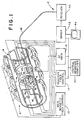
- Figure 1 is a diagrammatic illustration of a magnetic resonance imaging apparatus incorporating a first localised coil arrangement in accordance with the present invention;
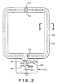
- Figure 2 is a plan view of the first localized coil arrangement;
- Figure 3 is a cross sectional view on the line 3-3 in Figure 2;
- Figure 4 is a schematic diagram illustrating electrical interface circuitry of the first coil arrangement;
- Figure 5 is a cross sectional view corresponding to the cross sectional view of Figure 3 of a second localized coil arrangement in accordance with the present invention;
- Figure 6 shows a third localized coil arrangement in accordance with the present invention incorporating a passive interface circuit;
- Figure 7 shows part of a fourth localized coil arrangement in accordance with the present invention incorporating an active interface circuit,
- Figure 8 is a view of part of a fifth localized coil arrangement in accordance with the present invention;
- Figure 9 shows a sixth localized coil arrangement in accordance with the present invention having a balanced coil configuration.
- Figure 10 shows a seventh localized coil arrangement in accordance with the present invention; and
- Figure 11 shows a part of an eighth localized coil arrangement in accordance with the present invention.
-
Referring to Figure 1, the magnetic resonance imaging apparatus includes a main magnetic field means A for establishing a generally uniform, main magnetic field longitudinally through an image region along a z-axis. A gradient field means B selectively produces magnetic field gradients transversely across the main magnetic field of the image region. A magnetic resonance excitation means C excites magnetic resonance in selected nuclei of a patient or subject disposed in the image region. The resonating nuclei generate radio frequency magnetic resonance signals which are received by a surface or localized coil D. More specifically, the surface coil is disposed adjacent a preselected region of the subject to be imaged such that it receives magnetic resonance signals from nuclei disposed in the preselected region of interest. Electronic processing circuitry E converts the received radio frequency signals into an image representation indicative of nuclei density, relaxation time, position, nuclei characteristics, or the like.
-
The main magnetic field means A includes a magnetic field control circuit 10 and a plurality of high power magnets 12. A gradient magnetic field control circuit or means 14 applies current pulses to gradient coils 16 to create gradients across the main magnetic field. The current pulse to each gradient coil is controlled by the gradient field means B to select the angular orientation of the transverse gradient field generated by a gradient field coil assembly 16. The resonance excitation means C includes a radio frequency transmitter 18 and transmission coil 20 to broadcast radio frequency (RF) signals that excite and manipulate magnetic resonance. Optionally, the localized coil D may be connected with the RF transmitter to apply the RF pulses to adjacent regions of the subject. A central computer 22 coordinates the sequence and timing of the gradient field pulses and the RF pulses.
-
The signals emitted by the relaxation of nuclei in the subject have components only in a plane that is normal to the direction of the static magnetic field, i.e. in the x-y plane, which is normal to the z-axis. Accordingly, only those conductors of the localized coil which intersect the x-y plane will detect the magnetic resonance signals. RF signals from the x-y plane induce a like RF current along the z-axis in the intersecting coil segment.
-
In high frequency magnetic resonance, the conductors contribute to a heavy interaction with the subject which results in Q loading and reduced sensitivity. When used as a transmitter, the RF current pulses through a z-axis conductor of the localized coil induce magnetic fields in the x-y plane. Magnetic resonance signal components not in the x-y planes, i.e. z-axis components, are attributable solely to noise. Accordingly, it is desirable to suppress reception of the z-axis RF field components.
-
The localized coil D includes a first or inner conductor 30 which defines a current path or loop along a surface of the subject adjacent the region of interest. A second or outer conductor or Faraday shield 32 extends parallel to the inner conductor and peripherally therearound. An electrical interconnection 34 interconnects first ends of the inner and outer electrical conductors. An electrical interface 36 couples the localized coil, particularly the second ends of the inner and outer conductors, with a flexible transmission cable 38.
-
The flexible cable 38 connects the localized coil with the remotely located processing circuitry E. More specifically, the cable conveys the received radio frequency signals from the localized coil to a radio frequency receiver 40. An imager 42 reconstructs an image representation from the received magnetic resonance signals and the magnetic field control and timing information from the central processor 22. The electronic image representation may be converted to a man-readable display by a video monitor or other display means 44.
-
With reference to FIGURES 2 and 3, the localized coil is a loop of coaxially constructed conductors closed upon itself. At a first end of the loop, the inner or center conductor 30 is shorted 34 to the outer conductor 32. More specific to the preferred embodiment, the outer conductor includes segments of copper tubing 32 which are discontinuous at a gap or opening 50. The inner conductor 30 is the center core of a coaxial cable separated from the outer conductor 32 by a dielectric insulator 52. At a second end, the inner conductor 30 becomes a signal output and the outer conductor 32 is electrically interconnected with each other and a ground 54. Preferably, the first and second ends of the coil are disposed adjacent the interface 36 and the gap 50 is disposed diametrically opposite.
-
The self resonance of the coaxial cable is governed in significant part by the inductance of the inner conductor and the shunt capacitance of the center conductor to the outer shield. Reducing the shunt capacitance raises the self resonance and Q value of the coil. The shunt capacitance can be reduced by increasing the diameter of the outer conductor or by reducing the dielectric constant of the inter-conductor insulating material 52. Higher velocity factor dielectrics for a given conductor geometry will raise the characteristic impedance and typically the Q value. Air is a suitable high velocity dielectric and is typically less lossy than materials with a high dielectric constant, hence lower velocity factor.
-
With continuing reference to FIGURE 2 and further reference to FIGURE 4, the interface circuit 38 includes a variable capacitor 60 for adjusting the resonant frequency of the coil. If the coil were operated above its parallel self resonant frequency, the coil would appear capacitive at the operating frequency. To cancel this capacitive reactance, an inductor 62 is connected in parallel with the capacitor 60 across the inner and outer conductors to enable the coil to be tuned to resonance. A preamplifier means 64 includes a single junction FET 66 connected in a common source configuration. That is, the inner conductor 30 is connected with the gate of the transistor. The source, like one end of the capacitor and inductor, is connected with the ground
-
54. The drain is connected with the transmission cable 38 to receive motive power therefrom, specifically a DC bias. Connecting the FET in a common source configuration allows the high impedance localized coil to see a high impedance load while driving a lower impedance cable, typically 50 ohms. The preamplified output from the transistor is conveyed superimposed with the DC bias on a pair of coaxial leads of the transmission cable 38. A pair of high speed switching diodes 68 are connected back to back across the coil and the system ground to protect the FET from excessive RF voltage during RF pulse transmission.
-
With this configuration, the localized coil D appears electrically as a parallel resonance structure trimmed to a selected frequency by the variable capacitor 60 and, if necessary, the inductor 62. The Faraday shielding renders the coil relatively insensitive to electrostatic fields from the environment. Moreover, the electrostatic field generated by excitation of the coil by external means, such as the radio frequency resonance excitation signal, is substantially contained between the inner and outer conductors of the coil. The coil couples magnetically to the environment because the inner loop is viewed from outside of the coil, whereas the outer conductor or shield is not a closed loop.
-
An incident magnetic field perpendicular to the x-z plane in which the coil lies induces a potential across the output of the coil to the gate of the transistor 66. The level of this potential is increased by the Q value of the coil in proportion to the square root of the Q. Because the Q value of the coil is damped by the magnetic coupling of the coil and the sample, and not by the electrostatic coupling, the available signal is greater than that obtained by an ordinary coil of similar size. Further, because the electrostatic field does not couple outside of the fixed coil geometry, the tuning of the coil is relatively unaffected by the sample.
-
To the coil, the input of the transistor 66 appears as a near open circuit which minimizes the effect of the transistor on the coils Q value. Further, impedance matching is not required. The coil effectively does not deliver power into the load. The FET input impedance sees the equivalent parallel resistance of the coil at resonance which, of course, is a function of the Q value. Because the transistor is physically adjacent the coil, the equivalent noise input voltage as defined by the transistor noise figure and the thermal noise tracks the coil impedance defined by the loaded Q value over a wide range of impedances. Preferably, the transistor is an FET of a type selected to have an IDSS on the same order as the ID specification for the best noise figure.
-
A DC power supply 70 is mounted in conjunction with the receiver 40 for applying a DC bias to the coaxial leads of the transmission cable 38. Specifically, a DC bias voltage source 72 is superimposed on the transmission line by a decoupling impedance 74. A DC blocking capacitor 76 blocks the DC bias voltage from reaching the input stage of the receiver 40.
-
With reference to FIGURE 5, the outer conductor 32 need not completely surround the inner conductor 30 in order to shield against electrostatic field losses. Rather, partially surrounding the inner conductor on the side toward the surface of the subject has been found to produce satisfactory shielding.
-
With reference to FIGURE 6, the interface 36 is a passive interface which is particularly advantageous for mid-field imagers and lower frequency applications. The passive interface includes a tuning capacitor 60 for adjusting the tuning, i.e. for adjusting the resonant frequency of the coil and interface to match the resonance signal center frequency. Optionally, the capacitor 60 may be a varactor diode to enable the coil system to be tuned remotely by superimposing a voltage on cable 38. A matching capacitance 78 matches the coil with the impedance of the cable 38, e.g. a 50 ohm cable. Optionally, an inductor may be connected in parallel to the matching capacitor to raise the self resonant frequency of the coil.
-
With reference to FIGURE 7, the interface circuit 36 includes a passive impedance matching network and an active decoupling system. The active decoupling system includes PIN diodes 80, 82 for selectively decoupling the localized coil from the cable. Particularly, when a positive DC bias or current is superimposed on the leads of the cable 38, the diodes are biased on and appear as a very low impedance to radio frequency signals. The diode 82 effectively shorts out the coil deresonating it. The diode 80 effectively connects a capacitor 84 and an inductor 86 in parallel. The inductor is selected to parallel resonate capacitor 84 at the operating frequency, effectively decoupling the coil from the rest of the system. When a negative voltage is superimposed on cable 38, the diodes are biased off and the coil operates as a pick up coil. A varicap diode 88 whose capacitance is remotely adjustable is used to optimize the system performance. In the illustrated embodiment, the varicap diode is biased such that adjusting a negative bias applied across the cable 38 adjusts the capacitance. Optionally, an inductor can be added analogous to inductor 62 of FIGURE 4 to raise the self resonance frequency. In operation, a positive DC bias is applied to the cable 38 when the scanner is exciting magnetic resonance. When a magnetic resonance signal is to be received, a negative bias of a magnitude selected to match the resonance frequency of the interface circuit with the center resonance frequency, and to provide an impedance match between the coil and the output load, in the preferred embodiment, the receiver 40.
-
With reference to FIGURE 8, the inductor 62 of the embodiment of FIGURES 1-6 enables physically large localized coils to be operated below their self resonance frequency. Alternately, operation below the self resonance frequency can be achieved by connecting capacitors 90, 92 in series with the inner conductor 30. In the preferred embodiment, the outer conductors have additional gaps generally midway between the gap or opening 50 and the ends of the coil to provide access for connecting the capacitors 90, 92. Electrical connectors 94, such as conductive sleeves, provide electrical continuity across the capacitor access gaps. Other numbers of capacitors may, of course, be provided, e.g. a larger plurality of capacitors may be symmetrically or asymmetrically arranged around the coil. Moreover, other constructions may be provided for maintaining electrical continuity of the outer conductor adjacent the capacitor, an integral or welded tubing section, metal leads, or the like. In this manner, the average voltage appearing between the inner conductor 30 and the outer conductor 32 is reduced which reduces the electrostatic field losses within the coil by distributing the radio frequency voltage.
-
With reference to FIGURE 9, a balanced coil configuration is provided which raises the self resonant frequency of the localized coil. Specifically, opposite ends of the center conductor 30 are both connected with the interface circuit 36. An adjustable tuning reactance 60 is connected across the ends of the inner conductor to tune the resonant frequency of the coil. A protection diode array 68 connects the ends of the inner conductor with the ground and the outer conductor. The gates of a pair of FET transistors 66a, 66b are each connected to one of the inner conductors. The FETs are connected in a common source configuration with their sources connected to ground and their drains connected to a balun 98. The balun matches the balanced coil configuration to the unbalanced transmission cable 38.
-
With reference to FIGURE 10, the preamplifier means 64 may include other solid state arrangements. Utilizing a MOSFET transistor offers the advantage of a higher impedance, hence, a higher coil Q value which can result in substantial gains in the signal-to-noise ratio when a level of loading on the coils is low. In the embodiment of Figure 10, a dual gate MOSFET 100 has a first gate 102 connected with the inner conductor. A second gate 104 is connected with a decoupling circuit 106 which derives a second gate bias from the drain supply.
-
With reference to Figure 11, a pair of crossed diodes 110 short the gap 50 in the outer conductor. Any incident radio frequency field of a large magnitude will cause the crossed diodes to conduct, thus shorting the gap and preventing the inner conductor from becoming visible to the RF magnetic field. In this manner, the pick up loop 30 can be isolated from the incident radio frequency magnetic resonance excitation fields.
-
It is to be appreciated that various coil configurations may be provided, such as saddle coils, solenoid coils, Helmholz pair coil geometries and the like.