EP0329504B1 - Service trolley - Google Patents
Service trolley Download PDFInfo
- Publication number
- EP0329504B1 EP0329504B1 EP19890400234 EP89400234A EP0329504B1 EP 0329504 B1 EP0329504 B1 EP 0329504B1 EP 19890400234 EP19890400234 EP 19890400234 EP 89400234 A EP89400234 A EP 89400234A EP 0329504 B1 EP0329504 B1 EP 0329504B1
- Authority
- EP
- European Patent Office
- Prior art keywords
- chassis
- load
- wheels
- handling trolley
- ground
- Prior art date
- Legal status (The legal status is an assumption and is not a legal conclusion. Google has not performed a legal analysis and makes no representation as to the accuracy of the status listed.)
- Expired - Lifetime
Links
Images


Classifications
-
- B—PERFORMING OPERATIONS; TRANSPORTING
- B62—LAND VEHICLES FOR TRAVELLING OTHERWISE THAN ON RAILS
- B62B—HAND-PROPELLED VEHICLES, e.g. HAND CARTS OR PERAMBULATORS; SLEDGES
- B62B3/00—Hand carts having more than one axis carrying transport wheels; Steering devices therefor; Equipment therefor
- B62B3/04—Hand carts having more than one axis carrying transport wheels; Steering devices therefor; Equipment therefor involving means for grappling or securing in place objects to be carried; Loading or unloading equipment
- B62B3/06—Hand carts having more than one axis carrying transport wheels; Steering devices therefor; Equipment therefor involving means for grappling or securing in place objects to be carried; Loading or unloading equipment for simply clearing the load from the ground
- B62B3/0612—Hand carts having more than one axis carrying transport wheels; Steering devices therefor; Equipment therefor involving means for grappling or securing in place objects to be carried; Loading or unloading equipment for simply clearing the load from the ground power operated
-
- B—PERFORMING OPERATIONS; TRANSPORTING
- B62—LAND VEHICLES FOR TRAVELLING OTHERWISE THAN ON RAILS
- B62B—HAND-PROPELLED VEHICLES, e.g. HAND CARTS OR PERAMBULATORS; SLEDGES
- B62B2301/00—Wheel arrangements; Steering; Stability; Wheel suspension
- B62B2301/08—Wheel arrangements; Steering; Stability; Wheel suspension comprising additional wheels to increase stability
-
- B—PERFORMING OPERATIONS; TRANSPORTING
- B62—LAND VEHICLES FOR TRAVELLING OTHERWISE THAN ON RAILS
- B62B—HAND-PROPELLED VEHICLES, e.g. HAND CARTS OR PERAMBULATORS; SLEDGES
- B62B2301/00—Wheel arrangements; Steering; Stability; Wheel suspension
- B62B2301/20—Resilient wheel suspension using springs
- B62B2301/23—Resilient wheel suspension using springs the pressure of the wheel on the ground being controlled, e.g. by the load or the wheel slip
-
- B—PERFORMING OPERATIONS; TRANSPORTING
- B62—LAND VEHICLES FOR TRAVELLING OTHERWISE THAN ON RAILS
- B62B—HAND-PROPELLED VEHICLES, e.g. HAND CARTS OR PERAMBULATORS; SLEDGES
- B62B3/00—Hand carts having more than one axis carrying transport wheels; Steering devices therefor; Equipment therefor
- B62B3/04—Hand carts having more than one axis carrying transport wheels; Steering devices therefor; Equipment therefor involving means for grappling or securing in place objects to be carried; Loading or unloading equipment
- B62B3/06—Hand carts having more than one axis carrying transport wheels; Steering devices therefor; Equipment therefor involving means for grappling or securing in place objects to be carried; Loading or unloading equipment for simply clearing the load from the ground
- B62B3/0625—Hand carts having more than one axis carrying transport wheels; Steering devices therefor; Equipment therefor involving means for grappling or securing in place objects to be carried; Loading or unloading equipment for simply clearing the load from the ground using rigid mechanical lifting mechanisms, e.g. levers, cams or gears
-
- B—PERFORMING OPERATIONS; TRANSPORTING
- B62—LAND VEHICLES FOR TRAVELLING OTHERWISE THAN ON RAILS
- B62B—HAND-PROPELLED VEHICLES, e.g. HAND CARTS OR PERAMBULATORS; SLEDGES
- B62B5/00—Accessories or details specially adapted for hand carts
- B62B5/06—Hand moving equipment, e.g. handle bars
- B62B5/063—Hand moving equipment, e.g. handle bars for low-lift hand trucks
Definitions
- the present invention relates to a handling trolley of the type comprising a chassis equipped with four lift wheels and a drive and steer wheel, which is located substantially between two of the four lift wheels, which are mounted relative to the chassis practically without suspension.
- elastic while between the steering and driving wheel and the chassis is provided an elastic suspension, which presses said steering and driving wheel on the ground with a predetermined elastic force and which includes a suitable actuating means, when actuated , modifying said elastic force, said actuating means being controlled by a load sensing device.
- handling trolley There are many models of handling trolley, with tray or platform for receiving loads, or with a fork for picking up and transporting loads, and with or without lifting and / or stacking capacity.
- the known carriages can be accompanied or transported driver.
- the present invention is applicable to all models of industrial truck, provided that they are of the above-mentioned type.
- handling trolleys of this type it is known to provide an actuating means making it possible to modify the application force and, consequently, the adhesion of the steering and driving wheel on the ground, for example to allow the trolley to cross an inclined ramp or to pass over a smooth or slippery surface (see for example patent applications FR 2570655 and EP 0209502).
- Said actuating means can be for example a hydraulic cylinder connected directly or indirectly to a support of the driving and steering wheel. It can be put into operation either by a manual control actuated by the driver of the trolley, for example using a control push button, or automatically using a detector, such as a strain gauge , a load cell, a pressure switch, etc. detecting a load placed on the platform or the fork of the industrial truck. In the case where the latter is equipped with a lifting cylinder making it possible to lower and raise the platform or the fork of the carriage, it is known to use the lifting cylinder itself as a load detector.
- the value of the pressure of the hydraulic fluid in the lifting cylinder can give an indication of the presence or absence of a load on the plate or the fork of the carriage and theoretically also an indication of the value of the load. It is then known to connect the jack which is used to modify the force of application of the driving and guiding wheel on the ground, on the same hydraulic circuit as the lifting jack, so that the first jack presses the driving wheel and directing on the ground with a force commensurate with the weight of the load carried by the industrial truck.
- the present invention therefore essentially aims to remedy this drawback, by providing a handling trolley in which means are provided to prevent the two lift wheels located on either side of the driving and steering wheel from being able to lift above the ground when the actuation means provided for modifying the force of application of said driving and steering wheel on the ground is put into operation.
- the handling trolley of the present invention is characterized in that the load sensing device is disposed between the chassis (or an element rigidly fixed to the chassis) and an element which is linked to one of the three wheels, namely the driving and steering wheel and the two wheels located on either side thereof, and which is at a fixed vertical distance from the ground.
- the actuating means can be constituted, in a known manner, by a hydraulic cylinder which can be supplied with hydraulic fluid from a hydraulic pump mechanically connected to an electric motor.
- the load sensing device can be constituted by a simple contactor or it can be constituted by a switching means controlled by a sensor sensitive to a compressive force. If the industrial truck is equipped with a hydraulic lifting cylinder, the latter and the jack forming the actuating means can be supplied with pressurized hydraulic fluid by respective hydraulic pumps or by the same pump.
- the switching means of the load sensing device can be electrically connected in the current supply circuit of the electric motor associated with the hydraulic pump serving to supply hydraulic fluid to the jack forming said actuating means.
- said switching means can be electrically connected in the current supply circuit of a solenoid valve hydraulically connected between the common hydraulic pump and the jack forming said actuating means.
- FIG. 1 shows, by way of example, a known handling trolley 10, of the type called pallet truck, with accompanying driver, in which the present invention can be implemented.
- the carriage 10 comprises a chassis 1 equipped with four lift wheels, namely two front idlers 2 and two rear wheels 3.
- the front wheels 2 are mounted in supports or yokes 4 which can rotate freely around vertical axes 5. None elastic suspension is not interposed between the chassis 1 and the wheels 2 and 3, that is to say that there is between the chassis 1 and the wheels 2 and 3 no element liable to deform substantially elastically and to authorize a relative vertical movement between the chassis 1 and any one of the wheels 2 and 3.
- a driving and steering wheel 6 which can be driven in rotation by an electric or hydraulic motor 7 and which can be oriented at will by an accompanying driver by means of an operating drawbar 8, to steer the carriage 10.
- the wheel 6 is pressed against the ground by a predetermined elastic force which can be modified by an actuating means, for example by a hydraulic cylinder 9.
- the chassis 1 may comprise a main chassis 11, under which the two front wheels 2 and the wheel 6 are mounted, and an auxiliary chassis 12, which extends rearward from the main chassis 11 and under which the two rear wheels 3.
- the auxiliary chassis 12 is mounted vertically movable relative to the main chassis 11.
- its front part 12a is connected to the main chassis 11 by two upper links 13 and by two lower links 14 (a single link 13 and a single link 14 are visible in Figure 1).
- At least one hydraulic lifting cylinder 15 is mounted between the main chassis 11 and the part 12a of the auxiliary chassis 12 to move the latter vertically.
- the part 12b of the auxiliary chassis 12, which extends horizontally towards the rear, is intended to support one or more loads 16.
- the part 12b can have, in known manner, either the shape of a plate, or the shape of 'a fork, and it can be raised and lowered at the same time as the part 12a.
- each of the two lower links 14 is constituted by one of the two branches of a bent pivoting lever, the other branch 17 of which is connected by a connecting rod 18 to one 19 of the two branches of another lever angled swivel, the other branch 21 of which carries, at its free end, one of the two rear wheels 3.
- the load 16 In service, whether the load 16 is unitary or divided, it may happen that its center of gravity G is in the region of the two rear wheels 3. Under these conditions, the rear wheels 3 support, in addition to a fraction of the weight of the carriage 10, all or almost all of the weight P of the load 16, while the front wheels 2 support almost only the remaining fraction of the self weight of the carriage 10. In other words, in the situation indicated above, whatever the value of the weight P of the load 16, the latter brings practically no additional weight to the front wheels 2.
- the elastic suspension which presses the wheel 6 on the ground exerts on the main frame 11, due to the reaction of the ground, a force which is directed vertically from bottom to top and which tends to lift the main frame 11. It follows that if, in the situation mentioned above, the accompanying driver actuates the hydraulic cylinder 9 in order to increase the pressure exerted by the wheel 6 on the ground, in order to increase the grip of said wheel, it may happen that the main frame 11 and, consequently, the front wheels 2 are actually lifted off the ground. It should indeed be known that the carriages of the kind of that shown in Figure 1 have a relatively low self-weight (often significantly lower than the weight of the load they are capable of transporting).
- the invention makes it possible to avoid this by providing a load detector which is disposed between the main chassis 11 and an element which is linked to one of the two front wheels 2 or to the wheel 6 and which is at a vertical distance. fixed relative to the ground.
- the charge detector can be produced in different forms.
- the handling trolley of the present invention can have a general structure similar to that of the trolley 10 of FIG. 1.
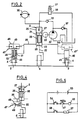
- FIG. 2 shows, schematically, a first embodiment of the present invention.
- the elements which are identical or which play the same role as those of Figure 1 are designated by the same reference numbers.
- FIG. 2 shows a front view of the two front wheels 2 and the driving and steering wheel 6 with its vertical pivot 22.
- the pivot 22 can slide axially in two guide rings 23 and 24 fixed in a cylindrical barrel 25 which forms the cylinder of the hydraulic cylinder 9.
- the cylindrical barrel 25 is supported by a cross member 26 which is part of the main chassis 11 ( Figure 1).
- the cylindrical barrel is supported by the crosspiece 26 so as to be able to rotate relative to the latter about a vertical axis, but without being able to move axially, therefore without possibility of movement in the vertical direction .
- a piston 27 which can slide in the cylindrical barrel 25, in the part of the latter which is located above the ring 24, so as to form with said part of the cylindrical barrel 25 the hydraulic cylinder 9.
- Said force can be increased by sending a hydraulic fluid under pressure into the chamber 31 of the hydraulic cylinder 9 by means of a pump 32.
- the pump 32 When the pump 32 is driven by an electric motor 33, it sucks the hydraulic fluid into a reservoir 34 and the discharge through a check valve 35 both to the chamber 31 and to a pressure accumulator 36.
- the latter allows the spring 28 to continue to play a role of elastic suspension even when the chamber 31 is filled with hydraulic fluid under pressure.
- a pressure 37 makes it possible to return the hydraulic fluid to the reservoir 34.
- the additional force which is due to the hydraulic fluid under pressure contained in the chamber 31 and which is added to the force of the spring 28 to press the wheel 6 on the ground, can be canceled by actuating a solenoid valve 38 which, when is open, allows the hydraulic fluid contained in the chamber 31 and in the accumulator 36 to be evacuated to the reservoir 34.
- the spring 28 can be replaced by a volume of oil enclosed in the chamber 39 of the cylindrical barrel 25, between the ring 24 and a piston 41 fixed to the pivot 22, the chamber 39 being connected by a pipe 42 to another pressure accumulator 43, as shown in FIG. 3.
- the chamber 44 of the accumulator 43 is inflated to a predetermined gas pressure so that the wheel 6 is pressed on the ground with a predetermined force.
- the support yoke 4 of each of the two front wheels 2 is provided with a vertical pivot 45 rotatably mounted in a housing 46.
- the two housings 46 are rigidly fixed respectively to the ends of the cross member 26.
- the aforementioned load sensing device may comprise a contactor 47, the housing 48 of which is rigidly fixed to the cross member 26 and the movable contact 49 of which is functionally connected to the pivot 45 of one of the two front wheels 2, via the operating member (lever or push button not shown in the diagram in FIG. 2) of the contactor 47.
- another contactor 47 ′ (shown in line mixed in FIG. 2) can also be associated with the pivot 45 of the other front wheel 2, in an arrangement similar to that of the contactor 47.
- the movable contact 49 of the contactor 47 can be connected functionally at the pivot 22 of the wheel 6 as shown in FIG. 4.
- a spring 51 having a small clearance in the vertical direction is interposed between the upper end wall of the housing 46 and a shoulder 52 of the pivot 45 of the front wheel 2 shown in the left part of FIG. 2.
- the another housing 46 shown in the right part of FIG. 2 also contains a spring similar to the spring 51 and bearing on a shoulder, similar to the shoulder 52, of the pivot 45 of the other front wheel 2.
- the two springs 51 tend to push up the housings 46 and the crosspiece 26 with the housing 48 of the contactor 47.
- the force of the spring or springs 51 is chosen so that the contactor 47 (and also the contactor 47 ′ when provided) is open when there is no load on the load receiving surface 12b of the carriage 10 (figure 1), and closed when the spring or springs 51 are comp rhymed as a result of the presence of a charge on said receiving surface 12b.
- the spring or springs 51 should not be considered as forming an elastic suspension for the front wheel or wheels 2.
- the arrangement is such that the amplitude of the vertical relative movement which is allowed by each spring 51 between the housing 46 and the corresponding pivot 45, is very small (approximately 1 to 3 mm) and corresponds to the opening and closing travel of the contacts of the contactor 47.
- a battery 53 supplies the electrical energy for the current supply of the electric motor 33.
- the contactor 47 is electrically connected in series with the motor 33. note that, in the case where two contactors 47 and 47 ′ are provided, these are preferably electrically connected both in series with the motor 33, in such a way that the latter can only be supplied with current when the two contactors 47 and 47 ′ are closed.
- a switch 54 can also be connected in series with the contactor 47 and the motor 33.
- the switch 54 can be actuated by means of a control button 55 provided on the handle 56 of the drawbar 8 ( figure 1).
- the battery 53 supplies an excitation current to the solenoid 57 of the solenoid valve 38 (FIG. 2) when a switch 58 is closed.
- the switch 58 can be actuated for example by means of a control button 59 also provided on the handle 56 of the operating drawbar 8.
- the fraction of the weight of the load 16 which is added to the cross-member 26 is sufficient to compress the spring or springs 51 and to cause the closure of the contactor (s) 47 and 47 ′.
- the driver decides that the pressure of the wheel 6 on the ground must be increased, for example so that the carriage 10 can more easily cross a ramp or a slippery area, the driver will close the switch 54 by pressing the button 55. Under these conditions, the electric motor 33 will be supplied with current, will drive the pump 32. The latter, drawing the hydraulic fluid from the reservoir 34, will discharge it into the chamber 31.
- FIG. 5 In the case where the chassis 1 of the carriage 10 consists of two parts 11 and 12, the part 12 of which can be moved vertically relative to the part 11 by means of at least one hydraulic cylinder 15, and in the case where the hydraulic cylinders 9 and 15 are supplied with hydraulic fluid respectively by two pumps each having its own electric drive motor, the diagram of FIG. 5 can be completed as shown in FIG. 6.
- the elements which are identical to those of FIG. 5 or which play the same role, are designated by the same reference numbers.
- the number 61 designates a switch which, when closed, causes the electric motor 62 to be supplied with current, which drives the hydraulic pump associated with the hydraulic lifting cylinder 15.
- the switch 61 is mechanically coupled with the 'switch 54 and the two switches can be actuated by the control button 55 provided on the handle 56 of the tiller 8 ( Figure 1).
- Another switch 63 is mechanically coupled with the switch 58, these two switches being able to be actuated at the same time by means of the control button 59 provided on the handle 56.
- the switch 63 causes the excitation of a solenoid 64.
- the solenoid 64 controls a solenoid valve 65 (FIG. 7) which is normally closed at rest and which, when actuated by the solenoid 64, authorizes the evacuation of the fluid contained in the hydraulic lifting cylinder 15 towards the tank 34.
- the load receiving surface 12b constituted for example by a fork
- the piston rod of the jack 15 being retracted
- the branches of the fork 12b are engaged under a load to be transported, for example a load carried by a pallet
- the driver presses the control button 55.
- the two switches 61 and 54 close, thereby causing the electric current to be supplied to the motor 62.
- the motor 33 remains not supplied as long that no load is applied to the cross member 26 and that the contactor 47 remains open. Consequently, initially, only the hydraulic lifting cylinder 15 is supplied with hydraulic fluid and lifts the fork 12b of the carriage 10.
- the additional force applied to the wheel 6 to increase its grip on the ground is produced automatically when the fork 12b of the carriage 10 grasps the load 16, provided that the fraction of the weight of the load which is reported at this time on the cross member 26 is sufficient to cause the closure of the contactor 47. Likewise, said additional force is automatically canceled when the load 16 is lowered.
- the two switches 58 and 63 close, the solenoids 57 and 64 are energized and the solenoid valves 38 and 65 authorize the return to the reservoir 34 of the hydraulic fluid contained in the jack 15 and in chamber 31 of cylinder 9.
- FIG. 7 and 8 show the modifications to be made respectively to the diagram of Figures 2 and 6 when the hydraulic cylinders 9 and 15 are supplied with hydraulic fluid by a single hydraulic pump, for example pump 32 with its electric drive motor. 33.
- the pump 32 supplies the lifting cylinder 15 by a pipe 66 into which two non-return valves are inserted, namely the valve 35 and another valve 67.
- a pipe 68 is connected in bypass on the pipe 66 between the valves 35 and 67, and it conducts the hydraulic fluid coming from the pump 32 towards the chamber 31 of the jack 9 and towards the pressure accumulator 36.
- a solenoid valve 69 In the pipe 68 is inserted a solenoid valve 69, of which the solenoid 71 is electrically connected in series with the contactor 47 and with the switch 54 as shown in FIG. 8. As also shown in FIG. 8, the electric motor 33 driving the pump 32 is connected in series with the switch 61.
- the solenoid valve 38 is hydraulically connected to the pipe 68 downstream of the solenoid valve 69, while the solenoid valve 65 is hydraulically connected to the pipe 66 downstream of the non-return valve 67.
- the electric motor 33 is supplied with current as soon as the control button 55 is pressed, thereby causing the lifting cylinder 15 to be supplied with hydraulic fluid through the valves 35 and 67
- the solenoid 71 doesn’t is not energized, the solenoid valve 69 remains closed and the chamber 31 of the jack 9 is not supplied with hydraulic fluid.
- the contactor 47 closes, thereby causing the opening of the solenoid valve 69.
- part of the hydraulic fluid supplied by the pump 32 is withdrawn by the pipe 68 to fill the pressure accumulator 36 and the chamber 31 of the jack 9.
- the pressure of the hydraulic fluid in the chamber 31 reaches a value sufficient to cause, by reaction, the lifting of the cross-member 26, the contactor 47 opens and, the solenoid 71 being no longer energized, the solenoid valve 69 closes.
- the pressure of the hydraulic fluid in the chamber 31 then keeps the value reached at the time of the opening of the contactor 47, to apply an additional force to the wheel 6 and increase the grip of the latter on the ground, as long as the solenoid valve 38 remains closed.
- said additional force is canceled by opening the solenoid valve 38, when the driver presses the button 59 to control the lowering of the fork 12b of the carriage 10 and the load that she supports.
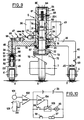
- FIG. 9 shows a concrete embodiment of the front wheel set 2, 6 of the carriage.
- the casing of the motor-reduction unit 7 for driving the driving and driving wheel 6 is fixed by bolts 72 to a flange 73 which is welded to the lower end of the pivot 22.
- This the latter is constituted by a shaft having a stepped profile, with shoulders 22a and 22b, the surfaces of which play the same role as the active surfaces of the pistons 27 and 41 of FIG. 3.
- the pivot 22 is mounted axially sliding in rings 23, 24 and 74, which are suitably kept axially spaced from each other in the cylindrical barrel 25 by tube segments 75 and 76 so as to form between them the chambers 31 and 39.
- the chamber 31 is connected by a pipe 77 to the pressure accumulator 36 and this the latter is connected by a hose 78 to the pump 32 (not shown in FIG. 9).
- the chamber 39 is connected by the pipe 42 to the pressure accumulator 43.
- the cylindrical barrel 25 is mounted for rotation, without the possibility of axial movement, in a central hole of the crosspiece 26 by means of a ball bearing 79.
- the pivot 22 is extended by a grooved end of the shaft 22c which is slidably mounted in the central hole of a ring 81 having internal grooves corresponding to those of the fluted shaft 22c.
- the ring 81 is kept axially spaced from the ring 74 by a tube segment 82 and it is rigidly fixed to the cylindrical barrel 25 by at least one screw 83. At its upper end, the barrel 25 is closed by a cover 84, which is kept axially spaced from the ring 81 by a tube segment 85.
- Two rings 86 and 87, of the "circlip" type ensure the cohesion of all the elements 23-25, 74-76 and 81-85.
- the drawbar 8 of FIG. 1 is attached to the cylindrical barrel 25 by means not shown, to allow the orientation of the driving driving wheel 6 by rotating the cylindrical barrel 25.
- the housings 46 in which the pivots 45 of the yokes 4 of the two front wheels 2 are rotatably mounted are formed by appendages of the cross member 26 extending vertically downward from the ends thereof.
- each appendage 46 comprises, in its lower part, a cylindrical cavity 88, of vertical axis, open downwards.
- Pivot 45 of the front wheel 2 is rotatably mounted in the cavity 88 by means of two anti-friction pads or rings 89.
- the part of the pivot 45 which is located between the two pads 89 has a reduced outside diameter so as to form a circular groove 91.
- a retaining pin 92 engaged in aligned holes 93 in the appendage 46 and in the groove 91 prevents the pivot 45 from coming out of the cavity 88.
- a hole 94 In the bottom of the cavity 88 is pierced a hole 94, also of vertical axis and having a diameter smaller than that of the cavity 88.
- a rod 95 is engaged in the hole 94 and can slide freely therein.
- a disc 96 At the lower end of the rod 95 is fixed a disc 96 which bears on the upper end of the pivot 45 by means of a ball 97.
- the spring 51 is interposed between the disc 96 and the bottom of the cavity 88.
- the spring 51 may for example be constituted by a stack of frustoconical washers of the "Belleville" washer type.
- the load sensing device consisted of one or two contactors 47, 47 ′ arranged between the frame (the cross member 26) and an element (the pivot 45 or the rod 94 or the pivot 22) which is located at a fixed vertical distance from the ground, so that the contactor 47 is closed and authorizes the operation of the actuating means (hydraulic cylinder 9) intended to increase the pressure of application of the driving and driving wheel 6 on the ground , when the crosspiece 26 occupies a relatively low position relative to said element 45 or 94 or 22, and in such a way that the contactor 47 is open and prevents or stops the operation of said means of actuation 9 when the cross-member 26 occupies a relatively higher position than the above-mentioned position with respect to said element 45 or 94 or 22.
- the load detector can be produced other than by a contactor, for example by a sensor sensitive to a pressure or to a compressive force, such as a strain gauge, a piezoelectric sensor, etc. ., which produces an electrical signal whose value depends on the value of the pressure or the compression force to which it is subjected, and which is associated with a switching means which can be controlled directly or after appropriate processing by the signal electric produced by said sensor.
- a sensor sensitive to a pressure or to a compressive force such as a strain gauge, a piezoelectric sensor, etc. .
- Figure 10 shows, by way of example, an electrical diagram including a pressure-sensitive sensor.
- the sensor 101 is connected to one of the two inputs of a comparator 102, the other input of which is connected to an adjustable reference voltage source 103.
- the output of the comparator 102 is connected, through an adaptation circuit and amplification 104 at the control input of a switching means 105 connected in series with the electric motor 33 driving the pump 32, in place of the contactor 47 described above.
- the switching means 105 may for example be an electromagnetic relay, a transistor, a diac, a triac, etc.
- the sensor 101 can for example be placed in place of the spring 51 between the disc 96 and the bottom of the cavity 88, the rod 95 and the contactor 47 then being removed, but the hole 94 can be kept for the passage of the conductors of electrical connection of the sensor 101.
- the reference voltage produced by the source 103 is for example adjusted so that the comparator 102 produces on its output a signal having a first value such as the switching means 105 is closed when the result of the forces applied to the crosspiece 26, directed from top to bottom, is greater than a predetermined value, and the comparator 102 produces on its output a signal having a second value such as the switching means 105 is open when said result of the forces applied to the crosspiece 26, directed from top to bottom, is lower than said predetermined value.
- FIG. 10 is similar to that of FIG. 5. It goes without saying, however, that in FIGS. 6 and 8, the contactors 47 could be replaced by a switching means such as the switching means 105 in FIG. 10, controlled in the same way by a sensor. 101 pressure sensitive.
Description
La présente invention concerne un chariot de manutention du type comprenant un châssis équipé de quatre roues de sustentation et d'une roue motrice et directrice, qui est située sensiblement entre deux des quatre roues de sustentation, lesquelles sont montées par rapport au châssis pratiquement sans suspension élastique, tandis qu'entre la roue directrice et motrice et le châssis est prévue une suspension élastique, qui presse ladite roue directrice et motrice sur le sol avec une force élastique prédéterminée et qui inclut un moyen d'actionnement apte, lorsqu'il est actionné, à modifier ladite force élastique, ledit moyen d'actionnement étant commandé par un dispositif détecteur de charge.The present invention relates to a handling trolley of the type comprising a chassis equipped with four lift wheels and a drive and steer wheel, which is located substantially between two of the four lift wheels, which are mounted relative to the chassis practically without suspension. elastic, while between the steering and driving wheel and the chassis is provided an elastic suspension, which presses said steering and driving wheel on the ground with a predetermined elastic force and which includes a suitable actuating means, when actuated , modifying said elastic force, said actuating means being controlled by a load sensing device.
Il existe de nombreux modèles de chariot de manutention, avec plateau ou plate-forme de réception des charges, ou avec une fourche de saisie et de transport des charges, et avec ou sans capacité de levage et/ou de gerbage des charges. En outre, les chariots connus peuvent être à conducteur accompagnant ou à conducteur transporté. La présente invention est applicable à tous les modèles de chariot de manutention, pourvu qu'ils soient du type susindiqué. Dans les chariots de manutention de ce type, il est connu de prévoir un moyen d'actionnement permettant de modifier la force d'application et, par suite, l'adhérence de la roue directrice et motrice sur le sol, par exemple pour permettre au chariot de franchir une rampe inclinée ou de passer sur une surface lisse ou glissante (voir par exemple les demandes de brevet FR 2570655 et EP 0209502). Ledit moyen d'actionnement peut être par exemple un vérin hydraulique relié directement ou indirectement à un support de la roue motrice et directrice. Il peut être mis en fonctionnement soit par une commande manuelle actionnée par le conducteur du chariot, par exemple à l'aide d'un bouton poussoir de commande, soit automatiquement à l'aide d'un détecteur, telle qu'une jauge de contrainte, une jauge dynamométrique, un pressostat, etc. détectant une charge placée sur le plateau ou la fourche du chariot de manutention. Dans le cas où ce dernier est équipé d'un vérin de levage permettant d'abaisser et de relever le plateau ou la fourche du chariot, il est connu d'utiliser le vérin de levage lui-même comme détecteur de charge. En effet, dans ce cas, la valeur de la pression du fluide hydraulique dans le vérin de levage peut donner une indication de la présence ou de l'absence d'une charge sur le plateau ou la fourche du chariot et théoriquement aussi une indication de la valeur de la charge. Il est alors connu de brancher le vérin qui sert à modifier la force d'application de la roue motrice et directrice sur le sol, sur le même circuit hydraulique que le vérin de levage, de telle façon que le premier vérin presse la roue motrice et directrice sur le sol avec une force en rapport avec le poids de la charge porté par le chariot de manutention.There are many models of handling trolley, with tray or platform for receiving loads, or with a fork for picking up and transporting loads, and with or without lifting and / or stacking capacity. In addition, the known carriages can be accompanied or transported driver. The present invention is applicable to all models of industrial truck, provided that they are of the above-mentioned type. In handling trolleys of this type, it is known to provide an actuating means making it possible to modify the application force and, consequently, the adhesion of the steering and driving wheel on the ground, for example to allow the trolley to cross an inclined ramp or to pass over a smooth or slippery surface (see for example patent applications FR 2570655 and EP 0209502). Said actuating means can be for example a hydraulic cylinder connected directly or indirectly to a support of the driving and steering wheel. It can be put into operation either by a manual control actuated by the driver of the trolley, for example using a control push button, or automatically using a detector, such as a strain gauge , a load cell, a pressure switch, etc. detecting a load placed on the platform or the fork of the industrial truck. In the case where the latter is equipped with a lifting cylinder making it possible to lower and raise the platform or the fork of the carriage, it is known to use the lifting cylinder itself as a load detector. Indeed, in this case, the value of the pressure of the hydraulic fluid in the lifting cylinder can give an indication of the presence or absence of a load on the plate or the fork of the carriage and theoretically also an indication of the value of the load. It is then known to connect the jack which is used to modify the force of application of the driving and guiding wheel on the ground, on the same hydraulic circuit as the lifting jack, so that the first jack presses the driving wheel and directing on the ground with a force commensurate with the weight of the load carried by the industrial truck.
Bien que les chariots de manutention antérieurement connus du type décrit ci-dessus constituent un progrès important par rapport aux chariots de manutention dans lesquels la roue motrice et directrice est pressée contre le sol avec une force élastique constante, ils présentent néanmoins un manque de stabilité lorsque le centre de gravité de la ou des charges transportées se trouve dans un plan vertical qui est voisin des deux roues de sustentation les plus éloignées de la roue motrice et directrice. En effet, dans ce cas, comme on le verra plus en détail dans la suite de la description, il peut arriver que les deux roues de sustentation qui se trouvent de part et d'autre de la roue motrice et directrice soient soulevées au-dessus du sol lorsque le vérin hydraulique modifiant la force d'application de la roue motrice et directrice sur le sol est mis en action. Ceci peut nuire gravement à la stabilité du chariot de manutention.Although the previously known handling carriages of the type described above constitute an important advance compared to handling carriages in which the driving and driving wheel is pressed against the ground with a constant elastic force, they nevertheless exhibit a lack of stability when the center of gravity of the transported load (s) is in a vertical plane which is close to both lift wheels furthest from the drive and steer wheel. Indeed, in this case, as will be seen in more detail in the following description, it may happen that the two lift wheels which are on either side of the driving and steering wheel are raised above from the ground when the hydraulic cylinder modifying the application force of the driving and driving wheel on the ground is put into action. This can seriously affect the stability of the industrial truck.
La présente invention a donc essentiellement pour but de remédier à cet inconvénient, en fournissant un chariot de manutention dans lequel des moyens sont prévus pour empêcher que les deux roues de sustentation situées de part et d'autre de la roue motrice et directrice puissent se soulever au-dessus du sol lorsque le moyen d'actionnement prévu pour modifier la force d'application de ladite roue motrice et directrice sur le sol est mis en fonctionnement.The present invention therefore essentially aims to remedy this drawback, by providing a handling trolley in which means are provided to prevent the two lift wheels located on either side of the driving and steering wheel from being able to lift above the ground when the actuation means provided for modifying the force of application of said driving and steering wheel on the ground is put into operation.
A cet effet, le chariot de manutention de la présente invention est caractérisé en ce que le dispositif détecteur de charge est disposé entre le châssis (ou un élément fixé rigidement au châssis) et un élément qui est lié à l'une des trois roues, à savoir la roue motrice et directrice et les deux roues situées de part et d'autre de celle-ci, et qui se trouve à une distance verticale fixe par rapport au sol.To this end, the handling trolley of the present invention is characterized in that the load sensing device is disposed between the chassis (or an element rigidly fixed to the chassis) and an element which is linked to one of the three wheels, namely the driving and steering wheel and the two wheels located on either side thereof, and which is at a fixed vertical distance from the ground.
Le moyen d'actionnement peut être constitué, de façon connue, par un vérin hydraulique qui peut être alimenté en fluide hydraulique à partir d'une pompe hydraulique reliée mécaniquement à un moteur électrique. Le dispositif détecteur de charge peut être constitué par un simple contacteur ou il peut être constitué par un moyen de commutation commandé par un capteur sensible à une force de compression. Si le chariot de manutention est équipé d'un vérin hydraulique de levage, ce dernier et le vérin formant le moyen d'actionnement peuvent être alimentés en fluide hydraulique sous pression par des pompes hydrauliques respectives ou par la même pompe. Dans le premier cas, le moyen de commutation du dispositif détecteur de charge peut être connecté électriquement dans le circuit d'alimentation en courant du moteur électrique associé à la pompe hydraulique servant à alimenter en fluide hydraulique le vérin formant ledit moyen d'actionnement. Dans le second cas, ledit moyen de commutation peut être connecté électriquement dans le circuit d'alimentation en courant d'une électrovanne branchée hydrauliquement entre la pompe hydraulique commune et le vérin formant ledit moyen d'actionnement.The actuating means can be constituted, in a known manner, by a hydraulic cylinder which can be supplied with hydraulic fluid from a hydraulic pump mechanically connected to an electric motor. The load sensing device can be constituted by a simple contactor or it can be constituted by a switching means controlled by a sensor sensitive to a compressive force. If the industrial truck is equipped with a hydraulic lifting cylinder, the latter and the jack forming the actuating means can be supplied with pressurized hydraulic fluid by respective hydraulic pumps or by the same pump. In the first case, the switching means of the load sensing device can be electrically connected in the current supply circuit of the electric motor associated with the hydraulic pump serving to supply hydraulic fluid to the jack forming said actuating means. In the second case, said switching means can be electrically connected in the current supply circuit of a solenoid valve hydraulically connected between the common hydraulic pump and the jack forming said actuating means.
D'autres caractéristiques et avantages de la présente invention apparaîtront au cours de la description qui va suivre de diverses formes d'exécution de l'invention données en référence aux dessins annexés sur lesquels:
- la figure 1 montre, en élévation latérale, un chariot de manutention, du type appelé transpalette, à conducteur accompagnant, dans lequel la présente invention peut être mise en oeuvre, certaines parties du chariot ayant été arrachées pour mieux montrer certains détails.
- La figure 2 est un schéma mécanique et hydraulique montrant une première forme d'exécution de la présente invention.
- La figure 3 montre une variante de réalisation d'une partie du schéma de la figure 2.
- La figure 4 montre une autre variante de réalisation d'une autre partie du schéma de la figure 2.
- La figure 5 est le schéma d'un circuit électrique utilisable en liaison avec le schéma de la figure 2 ou de la figure 4.
- La figure 6 est un schéma d'un autre circuit électrique utilisable en liaison avec le schéma de la figure 2 ou de la figure 4.
- La figure 7 est un schéma semblable à celui de la figure 2, montrant une autre forme d'exécution de la présente invention.
- La figure 8 est le schéma d'un circuit électrique utilisable avec le schéma de la figure 7.
- La figure 9 montre, en partie en élévation de face et en partie en coupe verticale, une forme concrète d'exécution du train de roues avant d'un chariot de manutention conforme à la présente invention.
- La figure 10 est un schéma électrique relatif à une autre forme d'exécution de la présente invention.
- Figure 1 shows, in side elevation, a handling trolley, of the type called pallet truck, with accompanying driver, in which the present invention can be implemented, certain parts of the trolley having been broken away to better show certain details.
- Figure 2 is a mechanical and hydraulic diagram showing a first embodiment of the present invention.
- FIG. 3 shows an alternative embodiment of part of the diagram in FIG. 2.
- FIG. 4 shows another alternative embodiment of another part of the diagram in FIG. 2.
- FIG. 5 is the diagram of an electrical circuit usable in conjunction with the diagram of FIG. 2 or of FIG. 4.
- FIG. 6 is a diagram of another electrical circuit usable in conjunction with the diagram in FIG. 2 or in FIG. 4.
- Figure 7 is a diagram similar to that of Figure 2, showing another embodiment of the present invention.
- FIG. 8 is the diagram of an electrical circuit usable with the diagram of FIG. 7.
- Figure 9 shows, partly in front elevation and partly in vertical section, a concrete embodiment of the front wheel set of a handling trolley according to the present invention.
- Figure 10 is an electrical diagram relating to another embodiment of the present invention.
La figure 1 montre, à titre d'exemple, un chariot de manutention connu 10, du genre appelé transpalette, à conducteur accompagnant, dans lequel la présente invention peut être mise en oeuvre. Le chariot 10 comprend un châssis 1 équipé de quatre roues de sustentation, à savoir deux roues folles avant 2 et deux roues arrière 3. Les roues avant 2 sont montées dans des supports ou chapes 4 pouvant tourner librement autour d'axes verticaux 5. Aucune suspension élastique n'est interposée entre le châssis 1 et les roues 2 et 3, c'est-à-dire qu'il n'y a entre le châssis 1 et les roues 2 et 3 aucun élément susceptible de se déformer sensiblement élastiquement et d'autoriser un déplacement vertical relatif entre le châssis 1 et l'une quelconque des roues 2 et 3.FIG. 1 shows, by way of example, a known
Sensiblement entre les deux roues avant 2 se trouve une roue motrice et directrice 6, qui peut être entraînée en rotation par un moteur électrique ou hydraulique 7 et qui peut être orientée à volonté par un conducteur accompagnant au moyen d'un timon de manoeuvre 8, pour diriger le chariot 10. La roue 6 est pressée contre le sol par une force élastique prédéterminée qui peut être modifiée par un moyen d'actionnement, par exemple par un vérin hydraulique 9.Significantly between the two
Le châssis 1 peut comprendre un châssis principal 11, sous lequel sont montées les deux roues avant 2 et la roue 6, et un châssis auxiliaire 12, qui s'étend vers l'arrière à partir du châssis principal 11 et sous lequel sont montées les deux roues arrière 3. Le châssis auxiliaire 12 est monté verticalement mobile par rapport au châssis principal 11. Par exemple, sa partie avant 12a est reliée au châssis principal 11 par deux biellettes supérieures 13 et par deux biellettes inférieures 14 (une seule biellette 13 et une seule biellette 14 sont visibles dans la figure 1). Au moins un vérin hydraulique de levage 15 est monté entre le châssis principal 11 et la partie 12a du châssis auxiliaire 12 pour déplacer ce dernier verticalement. La partie 12b du châssis auxiliaire 12, qui s'étend horizontalement vers l'arrière, est destinée à supporter une ou plusieurs charges 16. La partie 12b peut avoir, de façon connue, soit la forme d'un plateau, soit la forme d'une fourche, et elle peut être soulevée et abaissée en même temps que la partie 12a. En effet, chacune des deux biellettes inférieures 14 est constituée par l'une des deux branches d'un levier pivotant coudé, dont l'autre branche 17 est reliée par une bielle 18 à l'une 19 des deux branches d'un autre levier pivotant coudé, dont l'autre branche 21 porte, à son extrémité libre, l'une des deux roues arrière 3.The
En service, que la charge 16 soit unitaire ou divisée, il peut arriver que son centre de gravité G se trouve dans la région des deux roues arrière 3. Dans ces conditions, les roues arrière 3 supportent, en plus d'une fraction du poids propre du chariot 10, la totalité ou la quasi totalité du poids P de la charge 16, tandis que les roues avant 2 supportent presque uniquement la fraction restante du poids propre du chariot 10. Autrement dit, dans la situation indiquée plus haut, quelle que soit la valeur du poids P de la charge 16, cette dernière n'apporte pratiquement aucun poids supplémentaire sur les roues avant 2.In service, whether the
D'un autre côté, la suspension élastique qui presse la roue 6 sur le sol exerce sur le châssis principal 11, du fait de la réaction du sol, une force qui est dirigée verticalement de bas en haut et qui tend à soulever le châssis principal 11. Il en résulte que si, dans la situation évoquée plus haut, le conducteur accompagnant actionne le vérin hydraulique 9 afin d'augmenter la pression exercée par la roue 6 sur le sol, afin d'augmenter l'adhérence de ladite roue, il peut arriver que le châssis principal 11 et, par suite, les roues avant 2 soient effectivement soulevés au-dessus du sol. Il faut en effet savoir que les chariots du genre de celui représenté sur la figure 1 ont un poids propre relativement faible (souvent nettement plus faible que le poids de la charge qu'ils sont capables de transporter). En conséquence, lorsque le vérin hydraulique 9 est actionné, la force qui est appliquée par réaction au châssis principal 11 et qui est dirigée verticalement de bas en haut peut devenir plus grande que la fraction du poids propre du chariot 10 qui tend à maintenir les roues avant 2 en contact avec le sol, de sorte que le châssis principal 11 et les roues avant 2 se soulèvent au-dessus du sol. Dans cette situation, le chariot 10 est privé des éléments de stabilité que constituaient les deux roues avant 2. Il en résulte que la stabilité générale du chariot 10 peut être gravement compromise au détriment de la sécurité des personnes et des biens qui se trouvent sur le chariot ou à proximité de celui-ci lorsqu'il circule dans de telles conditions.On the other hand, the elastic suspension which presses the
Le risque que les roues avant 2 se soulèvent au-dessus du sol est encore agravé lorsque le chariot comporte un vérin hydraulique de levage 15 comme le chariot 10 de la figure 1, et que le vérin hydraulique 9 est alimenté en fluide hydraulique à partir du même circuit hydraulique que le vérin hydraulique de levage 15, de telle façon que la pression dans le vérin 9 soit proportionnelle au poids de la charge transportée. En effet, dans ce cas, sous l'effet du poids P, la réaction du sol sur les roues 3 tend à faire pivoter les leviers coudés 19, 21 dans le sens contraire des aiguilles d'une montre (en regardant la figure 1), ce qui comprime longitudinalement les bielles 18 y associées. A leur tour, les bielles 18 tendent à faire pivoter les leviers coudés 14, 17 dans le sens des aiguilles d'une montre, ce qui tend d'une part à soulever le châssis principal 11 et, d'autre part, à comprimer davantage le fluide hydraulique contenu dans le vérin hydraulique de levage 15. De cette disposition, il apparaît clairement que si la pression du fluide hydraulique dans le vérin 9 est indexée sur la pression du fluide hydraulique régnant dans le vérin de levage 15, pour appliquer la roue 6 fortement sur le sol en fonction du poids de la charge 16, un tel système aura pour effet, par réaction, d'inciter le châssis principal 11 et, par suite, les roues avant 2 à se soulever au-dessus du sol.The risk that the
L'invention permet d'éviter cela en prévoyant un détecteur de charge qui est disposé entre le châssis principal 11 et un élément qui est lié à l'une des deux roues avant 2 ou à la roue 6 et qui se trouve à une distance verticale fixe par rapport au sol. Comme on le verra plus loin, le détecteur de charge peut être réalisé sous différentes formes.The invention makes it possible to avoid this by providing a load detector which is disposed between the
Le chariot de manutention de la présente invention peut avoir une structure générale semblable à celle du chariot 10 de la figure 1. La figure 2 montre, de façon schématique, une première forme d'exécution de la présente invention. Dans la figure 2, les éléments qui sont identiques ou qui jouent le même rôle qui ceux de la figure 1 sont désignés par les mêmes numéros de référence.The handling trolley of the present invention can have a general structure similar to that of the
La figure 2, montre de face les deux roues avant 2 et la roue motrice et directrice 6 avec son pivot vertical 22. Le pivot 22 peut glisser axialement dans deux bagues de guidage 23 et 24 fixées dans un fût cylindrique 25 qui forme le cylindre du vérin hydraulique 9. Le fût cylindrique 25 est supporté par une traverse 26 qui fait partie du châssis principal 11 (figure 1). Comme on le verra plus loin, le fût cylindrique est supporté par la traverse 26 de manière à pouvoir tourner par rapport à celle-ci autour d'un axe vertical, mais sans pouvoir se déplacer axialement, donc sans possibilité de mouvement dans le sens vertical. A l'extrémité supérieure du pivot 22 est fixé un piston 27 qui peut coulisser dans le fût cylindrique 25, dans la partie de celui-ci qui se trouve au-dessus de la bague 24, de manière à former avec ladite partie du fût cylindrique 25 le vérin hydraulique 9.FIG. 2 shows a front view of the two
Un ressort hélicoïdal le compression 28, prenant appui à une extrémité contre la bague 24 et à son autre extrémité contre un épaulement 29 du pivot 22, presse la roue 6 sur le sol avec une force élastique prédéterminée. Ladite force peut être augmentée en envoyant un fluide hydraulique sous pression dans la chambre 31 du vérin hydraulique 9 au moyen d'une pompe 32. Quand la pompe 32 est entraînée par un moteur électrique 33, elle aspire le fluide hydraulique dans un réservoir 34 et le refoule à travers un clapet anti-retour 35 à la fois vers la chambre 31 et vers un accumulateur de pression 36. Ce dernier permet au ressort 28 de continuer à jouer un rôle de suspension élastique même quand la chambre 31 est remplie de fluide hydraulique sous pression. En cas de surpression accidentelle dans le circuit hydraulique, un limiteur de pression 37 permet de renvoyer le fluide hydraulique vers le réservoir 34.A compression
La force supplémentaire, qui est dûe au fluide hydraulique sous pression contenu dans la chambre 31 et qui s'ajoute à la force du ressort 28 pour presser la roue 6 sur le sol, peut être annulée en actionnant une électrovanne 38 qui, lorsqu'elle est ouverte, permet l'évacuation vers le réservoir 34 du fluide hydraulique contenu dans la chambre 31 et dans l'accumulateur 36.The additional force, which is due to the hydraulic fluid under pressure contained in the
Le ressort 28 peut être remplacé par un volume d'huile enfermé dans la chambre 39 du fût cylindrique 25, entre la bague 24 et un piston 41 fixé au pivot 22, la chambre 39 étant raccordée par un tuyau 42 à un autre accumulateur de pression 43, comme montré dans la figure 3. La chambre 44 de l'accumulateur 43 est gonflée à une pression de gaz prédéterminée pour que la roue 6 soit pressée sur le sol avec une force prédéterminée.The
Comme montré dans la figure 2, la chape de support 4 de chacune des deux roues avant 2 est pourvue d'un pivot vertical 45 monté à rotation dans un boîtier 46. Les deux boîtiers 46 sont fixés rigidement respectivement aux extrémités de la traverse 26.As shown in FIG. 2, the
Suivant une forme d'exécution de la présente invention, le dispositif détecteur de charge susmentionné peut comprendre un contacteur 47, dont le boîtier 48 est fixé rigidement à la traverse 26 et dont le contact mobile 49 est relié fonctionnellement au pivot 45 de l'une des deux roues avant 2, par l'intermédiaire de l'organe de manoeuvre (levier ou bouton-poussoir non montré dans le schéma de la figure 2) du contacteur 47. Si on le désire, un autre contacteur 47′ (montré en trait mixte dans la figure 2) peut être aussi associé au pivot 45 de l'autre roue avant 2, suivant une disposition semblable à celle du contacteur 47. Suivant une variante d'exécution, le contact mobile 49 du contacteur 47 peut être relié fonctionnellement au pivot 22 de la roue 6 comme montré dans la figure 4.According to one embodiment of the present invention, the aforementioned load sensing device may comprise a
Un ressort 51 ayant un faible débattement dans le sens vertical est interposé entre la paroi d'extrémité supérieure du boîtier 46 et un épaulement 52 du pivot 45 de la roue avant 2 montrée dans la partie gauche de la figure 2. De préférence, l'autre boîtier 46, montré dans la partie droite de la figure 2, contient aussi un ressort semblable au ressort 51 et prenant appui sur un épaulement, semblable à l'épaulement 52, du pivot 45 de l'autre roue avant 2. Comme les deux épaulement 52 se trouvent à une distance verticale fixe par rapport au sol, les deux ressorts 51 tendent à repousser vers le haut les boîtiers 46 et la traverse 26 avec le boîtier 48 du contacteur 47. De préférence, la force du ou des ressorts 51 est choisie de telle façon que le contacteur 47 (et aussi le contacteur 47′ lorsqu'il est prévu) est ouvert quand il n'y a aucune charge sur la surface de réception de charge 12b du chariot 10 (figure 1), et fermé quand le ou les ressorts 51 sont comprimés par suite de la présence d'une charge sur ladite surface de réception 12b.A
Contrairement à ce que pourrait laisser penser la représentation très schématique de la figure 2, le ou les ressorts 51 ne doivent pas être considérés comme formant une suspension élastique pour la ou les roues avant 2. En réalité, l'agencement est tel que l'amplitude du mouvement relatif vertical qui est permis par chaque ressort 51 entre le boîtier 46 et le pivot 45 correspondant, est très faible (environ 1 à 3 mm) et correspond à la course d'ouverture et de fermeture des contacts du contacteur 47.Contrary to what the very schematic representation of FIG. 2 might suggest, the spring or springs 51 should not be considered as forming an elastic suspension for the front wheel or
Comme montré dans la figure 5, une batterie 53 fournit l'énergie électrique pour l'alimentation en courant du moteur électrique 33. Le contacteur 47 est connecté électriquement en série avec le moteur 33. On notera que, dans le cas où il est prévu deux contacteurs 47 et 47′, ceux-ci sont de préférence connectés électriquement tous les deux en série avec le moteur 33, de telle façon que celui-ci ne puisse être alimenté en courant que quand les deux contacteurs 47 et 47′ sont fermés. Comme montré dans la figure 5, un interrupteur 54 peut être également connecté en série avec le contacteur 47 et le moteur 33. L'interrupteur 54 peut être actionné au moyen d'un bouton de commande 55 prévu sur la poignée 56 du timon 8 (figure 1). Comme cela est également montré dans la figure 5, la batterie 53 fournit un courant d'excitation au solénoïde 57 de l'électrovanne 38 (figure 2) quand un interrupteur 58 est fermé. L'interrupteur 58 peut être actionné par exemple au moyen d'un bouton de commande 59 également prévu sur la poignée 56 du timon de manoeuvre 8.As shown in FIG. 5, a
On décrira maintenant le fonctionnement du système. Quand aucune charge n'est présente sur la surface de réception 12b du chariot 10, le contacteur 47 est ouvert. Il en résulte que, même si le conducteur du chariot agit sur le bouton de commande 55 pour fermer l'interrupteur 54, le moteur 33 ne peut pas être alimenté en courant et, par suite, la chambre 31 du vérin hydraulique 9 ne peut pas être remplie de fluide hydraulique sous pression. En conséquence, aucune pression n'est exercée sur la paroi supérieure de la chambre 31, pression qui pourrait, autrement, provoquer le soulèvement du fût cylindrique 25 et de la traverse 26 et, par suite, le soulèvement des roues avant 2 au-dessus du sol.The operation of the system will now be described. When no load is present on the receiving
Quand une charge 16 est présente sur la surface de réception 12b du chariot 10, deux situations peuvent se présenter. Dans une première situation, la fraction du poids de la charge qui est rapportée sur la traverse 26 est insuffisante pour comprimer le ou les ressorts 51 et pour provoquer la fermeture du ou des contacteurs 47 et 47′. Une telle situation pourra par exemple se produire soit parce que le poids de la charge 16 est trop faible, soit parce que le centre de gravité G de la charge se trouve dans la région des roues arrière 3. Dans cette première situation, le fonctionnement du système est semblable à celui décrit plus haut en l'absence de charge sur la surface de réception 12b. Aucun fluide hydraulique sous pression ne peut être alors admis dans la chambre 31, de sorte qu'il n'y a pas de risque que les roues avant 2 soient soulevées au-dessus du sol.When a
Dans la seconde situation, la fraction du poids de la charge 16 qui est rapportée sur la traverse 26 est suffisante pour comprimer le ou les ressorts 51 et pour provoquer la fermeture du ou des contacteurs 47 et 47′. Si, dans cette seconde situation, le conducteur décide que la pression de la roue 6 sur le sol doit être augmentée, par exemple pour que le chariot 10 puisse franchir plus aisément une rampe ou une zone glissante, le conducteur fermera l'interrupteur 54 en appuyant sur le bouton 55. Dans ces conditions, le moteur électrique 33 sera alimenté en courant en entraînera la pompe 32. Cette dernière, puisant le fluide hydraulique dans le réservoir 34, le refoulera dans la chambre 31. Quand la pression du fluide hydraulique dans la chambre 31 atteint une valeur telle que la force exercée par le fluide hydraulique sur la paroi supérieure de la chambre 31 et dirigée de bas en haut dépasse la force, dirigée de haut en bas, correspondant à la fraction du poids de la charge qui est appliquée à la traverse et qui a provoqué la fermeture du ou des contacteurs 47 et 47′, ce ou ces contacteurs s'ouvrent. Le moteur 33 n'est alors plus alimenté en courant et la pompe 32 s'arrête. Le clapet anti-retour 35 se ferme et la pression du fluide hydraulique dans la chambre 31 reste à la valeur atteinte au moment de l'ouverture du ou des contacteurs 47 et 47′.In the second situation, the fraction of the weight of the
D'après ce qui précède, il ressort que avec l'arrangement du détecteur de charge conforme à la présente invention, la pression du fluide hydraulique dans la chambre 31 ne peut pas atteindre une valeur telle que le fût cylindrique 25 et la traverse 26 soient soulevés à un point tel que les roues avant 2 soient elles-mêmes soulevés au-dessus du sol. Il en résulte que les risques d'instabilité que l'on rencontrait avec les chariots antérieurement connus, sont éliminés.From the above, it appears that with the arrangement of the load detector according to the present invention, the pressure of the hydraulic fluid in the
Quand le conducteur du chariot décide d'annuler la force additionnelle, qui est due au fluide hydraulique sous pression dans la chambre 31 et qui s'ajoute à la force du ressort 28 pour presser la roue 6 sur le sol, il suffit qu'il ferme l'interrupteur 58 en appuyant sur le bouton 59. Dans ces conditions, le solénoïde 57 est excité et l'électrovanne 38 autorise l'évacuation du fluide hydraulique contenu dans la chambre 31 et dans l'accumulateur 36 vers le réservoir 34.When the driver of the carriage decides to cancel the additional force, which is due to the hydraulic fluid under pressure in the
Le système décrit en liaison avec les figures 2 à 5 fonctionne indépendamment du fait que le châssis 1 du chariot 10 est constitué par un unique ensemble rigide ou par deux parties 11 et 12 dont l'une (12) est verticalement mobile par rapport à l'autre partie 11. En conséquence, l'invention, telle qu'elle a été décrite plus haut, s'applique aussi bien à un chariot dont le châssis est constitué par un unique ensemble rigide, qu'à un chariot dont le châssis 1 est constitué par deux parties 11 et 12 comme celles montrées dans la figure 1.The system described in connection with FIGS. 2 to 5 operates independently of the fact that the
Dans le cas où le châssis 1 du chariot 10 est constitué par deux parties 11 et 12, dont la partie 12 peut être déplacée verticalement par rapport à la partie 11 au moyen d'au moins un vérin hydraulique 15, et dans le cas où les vérins hydrauliques 9 et 15 sont alimentés en fluide hydraulique respectivement par deux pompes ayant chacune son propre moteur électrique d'entraînement, le schéma de la figure 5 peut être complété comme montré sur la figure 6. Dans la figure 6, les éléments qui sont identiques à ceux de la figure 5 ou qui jouent le même rôle, sont désignés par les mêmes numeros de référence. Dans la figure 6, le numéro 61 désigne un interrupteur qui, quand il est fermé, provoque l'alimentation en courant du moteur électrique 62 qui entraîne la pompe hydraulique associée au vérin hydraulique de levage 15. L'interrupteur 61 est couplé mécaniquement avec l'interrupteur 54 et les deux interrupteurs peuvent être actionnés par le bouton de commande 55 prévu sur la poignée 56 du timon de manoeuvre 8 (figure 1). Un autre interrupteur 63 est couplé mécaniquement avec l'interrupteur 58, ces deux interrupteurs pouvant être actionnés en même temps au moyen du bouton de commande 59 prévu sur la poignée 56. Quand il est fermé, l'interrupteur 63 provoque l'excitation d'un solénoïde 64. Le solénoïde 64 commande une électrovanne 65 (figure 7) qui est normalement fermée au repos et qui, quand elle est actionnée par le solénoïde 64, autorise, l'évacuation du fluide contenu dans le vérin hydraulique de levage 15 vers le réservoir 34.In the case where the
Quand la surface de réception de charge 12b, constituée par exemple par une fourche, est en position basse (la tige du piston du vérin 15 étant rétractée), et quand les branches de la fourche 12b sont engagées sous une charge à transporter, par exemple une charge portée par une palette, le conducteur appuie sur le bouton de commande 55. Alors, les deux interrupteurs 61 et 54 se ferment, provoquant ainsi l'alimentation en courant électrique du moteur 62. Par contre, le moteur 33 reste non alimenté tant qu'aucune charge n'est appliquée à la traverse 26 et que le contacteur 47 reste ouvert. En conséquence, dans un premier temps, seul le vérin hydraulique de levage 15 est alimenté en fluide hydraulique et soulève la fourche 12b du chariot 10. Quand la fourche 12b du chariot 10 vient saisir la charge et que, de ce fait, une partie du poids de la charge est appliquée à la traverse 26 et provoque la fermeture du contacteur 47, le moteur électrique 33 est alors alimenté en courant, de sorte que le vérin hydraulique 9 est également alimenté en fluide hydraulique pour presser plus fortement la roue 6 sur le sol. Comme dans le mode de réalisation décrit précédemment, quand la pression du fluide dans le vérin hydraulique 9 atteint une valeur telle que la force exercée par le fluide hydraulique sur la paroi supérieure de la chambre 31 du vérin 9 devient légèrement plus grande que la force antagoniste, due à la charge, qui a provoqué la fermeture du contacteur 47, ce dernier contacteur s'ouvre, de sorte que le vérin hydraulique 9 cesse d'être alimenté en fluide hydraulique et que la pression dans la chambre 31 reste à la valeur atteinte au moment de l'ouverture du contacteur 47. Dans ce cas aussi, on est donc assuré que la pression du fluide hydraulique dans le vérin 9 ne pourra pas atteindre un niveau tel que les roues avant 2 soient soulevées au-dessus du sol. On notera que, dans cette forme d'exécution, la force additionnelle appliquée à la roue 6 pour augmenter son adhérence sur le sol est produite automatiquement au moment où la fourche 12b du chariot 10 saisit la charge 16, à la condition que la fraction du poids de la charge qui est rapportée à ce moment sur la traverse 26 soit suffisante pour provoquer la fermeture du contacteur 47. De même, ladite force additionnelle est automatiquement annulée quand la charge 16 est abaissée. En effet, quand le conducteur appuie sur le bouton de commande 59, les deux interrupteurs 58 et 63 se ferment, les solénoïdes 57 et 64 sont excités et les électrovannes 38 et 65 autorisent le retour vers le réservoir 34 du fluide hydraulique contenu dans le vérin 15 et dans chambre 31 du vérin 9.When the
Les figures 7 et 8 montrent les modifications à apporter respectivement au schéma des figures 2 et 6 quand les vérins hydrauliques 9 et 15 sont alimentés en fluide hydrauliques par une seule et même pompe hydraulique, par example la pompe 32 avec son moteur électrique d'entraînement 33. Comme montré dans la figure 7, la pompe 32 alimente le vérin de levage 15 par un tuyau 66 dans lequel sont insérés deux clapets anti-retour, à savoir le clapet 35 et un autre clapet 67. Un tuyau 68 est branché en dérivation sur le tuyau 66 entre les clapets 35 et 67, et il conduit le fluide hydraulique en provenance de la pompe 32 vers la chambre 31 du vérin 9 et vers l'accumulateur de pression 36. Dans le tuyau 68 est insérée une électrovanne 69, dont le solénoïde 71 est connecté électriquement en série avec le contacteur 47 et avec l'interrupteur 54 comme montré dans la figure 8. Comme le montre également la figure 8, le moteur électrique 33 d'entraînement de la pompe 32 est connecté en série avec l'interrupteur 61. L'électrovanne 38 est reliée hydrauliquement au tuyau 68 en aval de l'électrovanne 69, tandis que l'électrovanne 65 est reliée hydrauliquement au tuyau 66 en aval du clapet anti-retour 67.Figures 7 and 8 show the modifications to be made respectively to the diagram of Figures 2 and 6 when the
Dans la forme d'exécution des figures 7 et 8, le moteur électrique 33 est alimenté en courant dès que le bouton de commande 55 est enfoncé, provoquant ainsi l'alimentation du vérin de levage 15 en fluide hydraulique à travers les clapets 35 et 67. Par contre, tant que la fourche 12b du chariot 10 n'a pas saisi une charge et tant que la fraction du poids de la charge rapportée sur la traverse 26 n'a pas provoqué la fermeture du contacteur 47, le solénoïde 71 n'est pas excité, l'électrovanne 69 reste fermée et la chambre 31 du vérin 9 n'est pas alimentée en fluide hydraulique. Dès que la charge appliquée à la traverse 26 devient suffisante, le contacteur 47 se ferme, provoquant ainsi l'ouverture de l'électrovanne 69. A partir de ce moment, une partie du fluide hydraulique débitée par la pompe 32 est prélevée par le tuyau 68 pour remplir l'accumulateur de pression 36 et la chambre 31 du vérin 9. Quand la pression du fluide hydraulique dans la chambre 31 atteint une valeur suffisante pour provoquer, par réaction, le soulèvement de la traverse 26, le contacteur 47 s'ouvre et, le solénoïde 71 n'étant plus excité, l'électrovanne 69 se ferme. La pression du fluide hydraulique dans la chambre 31 garde alors la valeur atteinte au moment de l'ouverture du contacteur 47, pour appliquer une force additionnelle à la roue 6 et augmenter l'adhérence de celle-ci sur le sol, tant que l'électrovanne 38 reste fermée. Comme dans la forme d'exécution de la figure 6, ladite force additionnelle est annulée en ouvrant l'électrovanne 38, quand le conducteur appuie sur le bouton 59 pour commander l'abaissement de la fourche 12b du chariot 10 et de la charge qu'elle supporte.In the embodiment of FIGS. 7 and 8, the
Là encore, on voit que dans la forme d'exécution des figures 7 et 8, la pression du fluide hydraulique dans la chambre 31 du vérin 9 ne peut pas atteindre une valeur telle que les roues avant 2 soient soulevées au dessus du sol et qui, par suite, provoqueraient une perte de stabilité du chariot 10.Again, we see that in the embodiment of Figures 7 and 8, the pressure of the hydraulic fluid in the
La figure 9 montre une forme concrète d'exécution du train de roues avant 2, 6 du chariot. Comme montré dans la figure 9, le carter de l'ensemble moteur- réducteur 7 d'entraînement de la roue motrice et directrice 6 est fixé par des boulons 72 à une bride 73 qui est soudée à l'extrémité inférieure du pivot 22. Ce dernier est constitué par un arbre ayant un profil étagé, avec des épaulements 22a et 22b dont les surfaces jouent le même rôle que les surfaces actives des pistons 27 et 41 de la figure 3. Le pivot 22 est monté axialement glissant dans des bagues 23, 24 et 74, qui sont convenablement maintenues espacées axialement les unes des autres dans le fût cylindrique 25 par des segments de tube 75 et 76 de manière à former entre elles les chambres 31 et 39. La chambre 31 est reliée par un tuyau 77 à l'accumulateur de pression 36 et ce dernier est relié par un tuyau 78 à la pompe 32 (non montrée dans la figure 9). La chambre 39 est reliée par le tuyau 42 à l'accumulateur de pression 43. Le fût cylindrique 25 est monté à rotation, sans possibilité de mouvement axial, dans un trou central de la traverse 26 par l'intermédiaire d'un roulement à bille 79. A son extrémité supérieure, au-delà de la bague 74, le pivot 22 est prolongé par un bout d'arbre cannelé 22c qui est monté coulissant dans le trou central d'une bague 81 ayant des cannelures intérieures correspondant à celles de l'arbre cannelé 22c. La bague 81 est maintenue espacée axialement de la bague 74 par un segment de tube 82 et elle est fixée rigidement au fût cylindrique 25 par au moins une vis 83. A son extrémité supérieure, le fût 25 est obturé par un opercule 84, qui est maintenu espacé axialement de la bague 81 par un segment de tube 85. Deux anneaux 86 et 87, du genre "circlip" assurent la cohésion de l'ensemble des éléments 23-25, 74-76 et 81-85.Figure 9 shows a concrete embodiment of the
Le timon de manoeuvre 8 de la figure 1 est attaché au fût cylindrique 25 par des moyens non montrés, pour permettre l'orientation de la roue motrice directrice 6 en faisant tourner le fût cylindrique 25.The
Les boîtiers 46 dans lesquels les pivots 45 des chapes 4 des deux roues avant 2 sont montés à rotation, sont formés par des appendices de la traverse 26 s'étendant verticalement vers le bas à partir des extrémités de celles-ci. Comme montré dans la partie gauche de la figure 9, chaque appendice 46 comporte, dans sa partie inférieure, une cavité cylindrique 88, d'axe vertical, ouverte vers le bas. Le pivot 45 de la roue avant 2 est monté à rotation dans la cavité 88 par l'intermédiaire de deux coussinets ou bagues anti-friction 89. La partie du pivot 45 qui se trouve entre les deux coussinets 89 a un diamètre extérieur réduit de manière à former une gorge circulaire 91. Une cheville de retenue 92 engagée dans des trous alignés 93 de l'appendice 46 et dans la gorge 91 empêche le pivot 45 de sortir de la cavité 88.The
Dans le fond de la cavité 88 est percé un trou 94, également d'axe vertical et ayant un diamètre plus petit que celui de la cavité 88. Une tige 95 est engagée dans le trou 94 et peut coulisser librement dans celui-ci. A l'extrémité inférieure de la tige 95 est fixé un disque 96 qui prend appui sur l'extrémité supérieure du pivot 45 par l'intermédiaire d'une bille 97. Le ressort 51 est interposé entre le disque 96 et le fond de la cavité 88. Le ressort 51 peut être par exemple constitué par un empilage de rondelles tronconiques du genre rondelles "Belleville". Quand le chariot de manutention 10 est à vide, l'extrémité supérieure de la tige 95 se trouve à proximité immédiate d'un galet 98 monté à l'extrémité libre du levier de manoeuvre 99 du contacteur 47, dont le boîtier 48 est fixé à la traverse 26.In the bottom of the
Dans ce qui précède, le dispositif détecteur de charge était constitué par un ou deux contacteurs 47, 47′ disposés entre le châssis (la traverse 26) et un élément (le pivot 45 ou la tige 94 ou le pivot 22) qui se trouve à une distance verticale fixe par rapport au sol, de telle façon que le contacteur 47 soit fermé et autorise le fonctionnement du moyen d'actionnement (vérin hydraulique 9) prévu pour augmenter la pression d'application de la roue motrice et directrice 6 sur le sol, quand la traverse 26 occupe une position relativement basse par rapport audit élément 45 ou 94 ou 22, et de telle façon que le contacteur 47 soit ouvert et empêche ou fait cesser le fonctionnement dudit moyen d'actionnement 9 quand la traverse 26 occupe une position relativement plus haute que la position susmentionnée par rapport audit élément 45 ou 94 ou 22.In the above, the load sensing device consisted of one or two
Il va cependant de soi que le détecteur de charge peut être réalisé autrement que par un contacteur, par exemple par un capteur sensible à une pression ou à une force de compression, telle qu'une jauge de contrainte, un capteur piézo-électrique, etc., qui produit un signal électrique dont la valeur dépend de la valeur de la pression ou de la force de compression à laquelle il est soumis, et qui est associé à un moyen de commutation pouvant être commandé directement ou après un traitement approprié par le signal électrique produit par ledit capteur.It goes without saying, however, that the load detector can be produced other than by a contactor, for example by a sensor sensitive to a pressure or to a compressive force, such as a strain gauge, a piezoelectric sensor, etc. ., which produces an electrical signal whose value depends on the value of the pressure or the compression force to which it is subjected, and which is associated with a switching means which can be controlled directly or after appropriate processing by the signal electric produced by said sensor.
La figure 10 montre, à titre d'exemple, un schéma électrique incluant un capteur sensible à la pression. Le capteur 101 est connecté à l'une des deux entrées d'un comparateur 102, dont l'autre entrée est connectée à une source de tension de référence ajustable 103. La sortie du comparateur 102 est connectée, à travers un circuit d'adaptation et d'amplification 104 à l'entrée de commande d'un moyen de commutation 105 connecté en série avec le moteur électrique 33 d'entraînement de la pompe 32, à la place du contacteur 47 précédemment décrit. Le moyen de commutation 105 peut être par exemple un relais électromagnétique, un transistor, une diac, une triac, etc.Figure 10 shows, by way of example, an electrical diagram including a pressure-sensitive sensor. The
Le capteur 101 peut être par exemple disposé à la place du ressort 51 entre le disque 96 et le fond de la cavité 88, la tige 95 et le contacteur 47 étant alors supprimés, mais le trou 94 pouvant être conservé pour le passage des conducteurs de raccordement électrique du capteur 101. La tension de référence produite par la source 103 est par exemple ajustée de telle façon que le comparateur 102 produise sur sa sortie un signal ayant une première valeur telle que le moyen de commutation 105 est fermé quand la résultante des forces appliquées à la traverse 26, dirigée de haut en bas, est plus grande qu'une valeur prédéterminée, et que le comparateur 102 produit sur sa sortie un signal ayant une seconde valeur telle que le moyen de commutation 105 est ouvert quand ladite résultante des forces appliquées à la traverse 26, dirigée de haut en bas, est plus faible que ladite valeur prédéterminée. De cette manière, en aucun cas les deux roues 2 ne peuvent être soulevées au-dessus du sol lorsqu'un fluide hydraulique sous pression est envoyé dans la chambre 31 du vérin 9. Pour le reste, le schéma de la figure 10 est semblable à celui de la figure 5. Il va cependant de soi que dans les figures 6 et 8, les contacteurs 47 pourraient être remplacés par un moyen de commutation tel que le moyen de commutation 105 de la figure 10, commandé de la même manière par un capteur 101 sensible à une pression.The
Il est du reste bien entendu que les formes d'exécution de la présente invention qui ont été décrites ci-dessus ont été données à titre d'exemple purement indicatif et nullement limitatif, et que de nombreuses modifications peuvent être facilement apportées par l'homme de l'art sans pour autant sortir du cadre de la présente invention.It is moreover clearly understood that the embodiments of the present invention which have been described above have been given by way of purely indicative and in no way limiting example, and that numerous modifications can be easily made by man. art without departing from the scope of the present invention.
Claims (10)
Applications Claiming Priority (2)
| Application Number | Priority Date | Filing Date | Title |
|---|---|---|---|
| FR8801035 | 1988-01-29 | ||
| FR8801035A FR2626535B1 (en) | 1988-01-29 | 1988-01-29 | TRUCK |
Publications (2)
| Publication Number | Publication Date |
|---|---|
| EP0329504A1 EP0329504A1 (en) | 1989-08-23 |
| EP0329504B1 true EP0329504B1 (en) | 1991-10-23 |
Family
ID=9362752
Family Applications (1)
| Application Number | Title | Priority Date | Filing Date |
|---|---|---|---|
| EP19890400234 Expired - Lifetime EP0329504B1 (en) | 1988-01-29 | 1989-01-27 | Service trolley |
Country Status (3)
| Country | Link |
|---|---|
| EP (1) | EP0329504B1 (en) |
| DE (1) | DE68900343D1 (en) |
| FR (1) | FR2626535B1 (en) |
Cited By (16)
| Publication number | Priority date | Publication date | Assignee | Title |
|---|---|---|---|---|
| DE4432620A1 (en) * | 1994-09-14 | 1996-04-11 | Jungheinrich Ag | Industrial truck |
| US6752224B2 (en) | 2002-02-28 | 2004-06-22 | Stryker Corporation | Wheeled carriage having a powered auxiliary wheel, auxiliary wheel overtravel, and an auxiliary wheel drive and control system |
| US6772460B2 (en) | 1996-04-12 | 2004-08-10 | Hill-Rom Services, Inc. | Pedal arrangement for stretcher apparatus |
| US6772850B1 (en) | 2000-01-21 | 2004-08-10 | Stryker Corporation | Power assisted wheeled carriage |
| US6902019B2 (en) | 1999-09-15 | 2005-06-07 | Hill-Rom Services, Inc. | Stretcher having a motorized wheel |
| US7644458B2 (en) | 1993-01-21 | 2010-01-12 | Hill-Rom Services, Inc. | Hospital bed |
| US7789187B2 (en) | 2008-01-29 | 2010-09-07 | Hill-Rom Services, Inc. | Push handle with pivotable handle post |
| US7882582B2 (en) | 2006-10-13 | 2011-02-08 | Hill-Rom Services, Inc. | User interface and control system for powered transport device of a patient support apparatus |
| US7886377B2 (en) | 2006-10-13 | 2011-02-15 | Hill-Rom Services, Inc. | Push handle with rotatable user interface |
| US7953537B2 (en) | 2008-02-29 | 2011-05-31 | Hill-Rom Services, Inc. | Algorithm for power drive speed control |
| US8016301B2 (en) | 2006-01-19 | 2011-09-13 | Hill-Rom Services, Inc. | Stretcher foot pedal arrangement |
| US8056162B2 (en) | 2007-04-26 | 2011-11-15 | Hill-Rom Services, Inc. | Patient support apparatus with motorized traction control |
| US8442738B2 (en) | 2009-10-12 | 2013-05-14 | Stryker Corporation | Speed control for patient handling device |
| US8757308B2 (en) | 2009-09-10 | 2014-06-24 | Hill-Rom Services Inc. | Powered transport system and control methods |
| US9707143B2 (en) | 2012-08-11 | 2017-07-18 | Hill-Rom Services, Inc. | Person support apparatus power drive system |
| DE102016112511A1 (en) * | 2016-07-07 | 2018-01-11 | Blickle Räder + Rollen GmbH u. Co. KG | Support roller, vehicle with support roller and method for stabilizing a vehicle |
Families Citing this family (23)
| Publication number | Priority date | Publication date | Assignee | Title |
|---|---|---|---|---|
| DE4226936C1 (en) * | 1992-08-14 | 1994-03-17 | Jungheinrich Ag | Industrial truck, in particular driverless vehicle |
| DE4227954C2 (en) * | 1992-08-22 | 1996-03-14 | Jungheinrich Ag | Three-wheel industrial truck |
| FR2698826B1 (en) * | 1992-12-07 | 1995-02-10 | Loc Manutention | Wheel wear compensator for pallet truck type handling trolley. |
| DE4309009A1 (en) * | 1993-03-20 | 1994-09-22 | Aft Gmbh | Transport unit of a floor transport system |
| DE4310257C2 (en) * | 1993-03-30 | 1995-02-23 | Jungheinrich Ag | Industrial truck |
| DE4401257C2 (en) * | 1994-01-18 | 1996-08-29 | Jungheinrich Ag | Pallet truck |
| DE4434327B4 (en) * | 1994-09-26 | 2005-12-01 | Linde Ag | Pallet truck with a load-dependent prestressed drive unit |
| SE509022C2 (en) * | 1997-11-28 | 1998-11-30 | Bt Ind Ab | Device for truck support wheels |
| DE19807849C2 (en) * | 1998-02-25 | 1999-12-23 | Jungheinrich Ag | Pallet truck with adjustable support rollers |
| DE10033801A1 (en) * | 2000-07-12 | 2002-01-24 | Fiat Om Carrelli Elevatori | Industrial truck used as a pallet truck comprises a drive part and a loading part with a guiding drive wheel and castors arranged in the region of the drive part and rotating about a vertical axis |
| ATE472991T1 (en) | 2004-12-01 | 2010-07-15 | Borringia Ind Ag | WHEELED OBJECT FOR USE BY A WALKING PERSON |
| US7770904B2 (en) | 2005-04-14 | 2010-08-10 | Nmhg Oregon, Llc | Stability system for an industrial vehicle |
| EP1868829B1 (en) * | 2005-04-14 | 2012-09-05 | NACCO Materials Handling Group, Inc. | Stability system for an industrial vehicle |
| DE102006041684A1 (en) * | 2006-09-06 | 2008-03-27 | Jungheinrich Ag | Pre-assembly unit for driving a truck |
| DE102008047022A1 (en) * | 2008-09-13 | 2010-03-18 | Jungheinrich Ag | Chassis for an industrial truck |
| ES1070429Y (en) * | 2009-06-01 | 2009-11-16 | Aranguren Com Del Embalaje S L | IMPROVED TRASPALET |
| EP2354078B1 (en) * | 2010-01-27 | 2013-08-28 | BT Products AB | Industrial truck |
| US9259369B2 (en) | 2012-09-18 | 2016-02-16 | Stryker Corporation | Powered patient support apparatus |
| US10004651B2 (en) | 2012-09-18 | 2018-06-26 | Stryker Corporation | Patient support apparatus |
| CN103496398B (en) * | 2013-10-16 | 2015-11-11 | 中国人民解放军总装备部军械技术研究所 | A kind of five take turns four-way drives traveling steering swivel system |
| US10568792B2 (en) | 2015-10-28 | 2020-02-25 | Stryker Corporation | Systems and methods for facilitating movement of a patient transport apparatus |
| DE102017103024A1 (en) | 2017-02-15 | 2018-08-16 | Hubtex Maschinenbau Gmbh & Co. Kg | Truck |
| CZ31282U1 (en) * | 2017-06-15 | 2017-12-11 | Vladimír Fila | A transport cart |
Family Cites Families (3)
| Publication number | Priority date | Publication date | Assignee | Title |
|---|---|---|---|---|
| DE3106027C2 (en) * | 1981-02-19 | 1985-11-28 | Jungheinrich Unternehmensverwaltung Kg, 2000 Hamburg | A lift truck with a height-adjustable wheel hub drive |
| JPH0613244B2 (en) * | 1984-08-28 | 1994-02-23 | 三菱自動車工業株式会社 | Vehicle height adjustment device |
| FR2570655B1 (en) * | 1984-09-26 | 1989-03-24 | Prat Cie Ets A | VEHICLE, ESPECIALLY HANDLING TROLLEY |
-
1988
- 1988-01-29 FR FR8801035A patent/FR2626535B1/en not_active Expired - Lifetime
-
1989
- 1989-01-27 EP EP19890400234 patent/EP0329504B1/en not_active Expired - Lifetime
- 1989-01-27 DE DE8989400234T patent/DE68900343D1/en not_active Expired - Lifetime
Cited By (26)
| Publication number | Priority date | Publication date | Assignee | Title |
|---|---|---|---|---|
| US7644458B2 (en) | 1993-01-21 | 2010-01-12 | Hill-Rom Services, Inc. | Hospital bed |
| DE4432620A1 (en) * | 1994-09-14 | 1996-04-11 | Jungheinrich Ag | Industrial truck |
| US6772460B2 (en) | 1996-04-12 | 2004-08-10 | Hill-Rom Services, Inc. | Pedal arrangement for stretcher apparatus |
| US8397846B2 (en) | 1999-09-15 | 2013-03-19 | Hill-Rom Services, Inc. | Patient support apparatus with powered wheel |
| US6902019B2 (en) | 1999-09-15 | 2005-06-07 | Hill-Rom Services, Inc. | Stretcher having a motorized wheel |
| US8240410B2 (en) | 1999-09-15 | 2012-08-14 | Hill-Rom Services, Inc. | Patient support apparatus with powered wheel |
| US7011172B2 (en) | 1999-09-15 | 2006-03-14 | Hill-Rom Services | Patient support apparatus having a motorized wheel |
| US7530412B2 (en) | 1999-09-15 | 2009-05-12 | Hill-Rom Services, Inc. | Method of making and using a patient support apparatus having a motorized drive assembly |
| US7007765B2 (en) | 2000-01-21 | 2006-03-07 | Stryker Corporation | Method for driving a wheeled carriage |
| US6772850B1 (en) | 2000-01-21 | 2004-08-10 | Stryker Corporation | Power assisted wheeled carriage |
| US6752224B2 (en) | 2002-02-28 | 2004-06-22 | Stryker Corporation | Wheeled carriage having a powered auxiliary wheel, auxiliary wheel overtravel, and an auxiliary wheel drive and control system |
| US8016301B2 (en) | 2006-01-19 | 2011-09-13 | Hill-Rom Services, Inc. | Stretcher foot pedal arrangement |
| US7886377B2 (en) | 2006-10-13 | 2011-02-15 | Hill-Rom Services, Inc. | Push handle with rotatable user interface |
| US8474073B2 (en) | 2006-10-13 | 2013-07-02 | Hill-Rom Services, Inc. | User interface for power drive system of a patient support apparatus |
| US7882582B2 (en) | 2006-10-13 | 2011-02-08 | Hill-Rom Services, Inc. | User interface and control system for powered transport device of a patient support apparatus |
| US8756726B2 (en) | 2006-10-13 | 2014-06-24 | Hill-Rom Services, Inc. | User interface for power drive system of a patient support apparatus |
| US8056162B2 (en) | 2007-04-26 | 2011-11-15 | Hill-Rom Services, Inc. | Patient support apparatus with motorized traction control |
| US7789187B2 (en) | 2008-01-29 | 2010-09-07 | Hill-Rom Services, Inc. | Push handle with pivotable handle post |
| US7953537B2 (en) | 2008-02-29 | 2011-05-31 | Hill-Rom Services, Inc. | Algorithm for power drive speed control |
| US8260517B2 (en) | 2008-02-29 | 2012-09-04 | Hill-Rom Services, Inc. | Patient support apparatus with drive wheel speed control |
| US8757308B2 (en) | 2009-09-10 | 2014-06-24 | Hill-Rom Services Inc. | Powered transport system and control methods |
| US8442738B2 (en) | 2009-10-12 | 2013-05-14 | Stryker Corporation | Speed control for patient handling device |
| US9707143B2 (en) | 2012-08-11 | 2017-07-18 | Hill-Rom Services, Inc. | Person support apparatus power drive system |
| US10588803B2 (en) | 2012-08-11 | 2020-03-17 | Hill-Rom Services, Inc. | Person support apparatus power drive system |
| DE102016112511A1 (en) * | 2016-07-07 | 2018-01-11 | Blickle Räder + Rollen GmbH u. Co. KG | Support roller, vehicle with support roller and method for stabilizing a vehicle |
| US11420666B2 (en) | 2016-07-07 | 2022-08-23 | Blickle Räder + Rollen GmbH u. Co. KG | Support roller, vehicle with a support roller and method for stabilizing a vehicle |
Also Published As
| Publication number | Publication date |
|---|---|
| FR2626535B1 (en) | 1991-08-16 |
| EP0329504A1 (en) | 1989-08-23 |
| FR2626535A1 (en) | 1989-08-04 |
| DE68900343D1 (en) | 1991-11-28 |
Similar Documents
| Publication | Publication Date | Title |
|---|---|---|
| EP0329504B1 (en) | Service trolley | |
| FR2668516A1 (en) | CONTROL SYSTEM FOR AUTOMATICALLY CONTROLLING OPERATING MEANS OF AN EXCAVATOR. | |
| FR2659953A1 (en) | TRANSPALETTE TROLLEY, ELECTRIC, GUIDE USING THE TIMON. | |
| FR3068026A1 (en) | DEVICE FOR HANDLING OBJECT | |
| EP0701963B2 (en) | Motorised lift truck with telescopic arm | |
| EP0905083B1 (en) | Lift truck with mast adapted to be mounted on the back of a transport vehicle | |
| FR3064619A1 (en) | METHOD AND DEVICE FOR SUPPORTING A WHEEL | |
| FR2800363A1 (en) | FORK LIFT TRUCK | |
| FR2606765A1 (en) | Support-distributing mechanism for handling- and lifting-trucks, particularly pallet trucks and stackers | |
| FR2646391A1 (en) | AUTONOMOUS PALLET WITH REMOVABLE WHEELS FOR THE TRANSPORT OF LOADS | |
| FR2459779A1 (en) | Container hoist with lifting frame - is actuated by hydraulic jacks operated in support frame with sliding central section | |
| FR2598142A1 (en) | FORK LIFT TRUCK WITH AN ORIENTABLE CONTROL BLOCK AND A MOBILE HEAD CARRIER ASSEMBLY. | |
| FR2976892A1 (en) | Transport carriage i.e. industrial lorry for transporting e.g. pallets, has supporting unit including autonomous wheel connected to rolling base, where connecting device applies force for pressing wheel independently against ground | |
| EP0909664B1 (en) | Dolly for towing and/or handling for the recovery of vehicles mounted on wheels | |
| FR2661161A3 (en) | PALLET CONVEYOR. | |
| CH664146A5 (en) | Hand propelled trolley - has fork lift mounted on sliding frame actuated by electrically-driven screwed spindles | |
| FR2607076A1 (en) | Vehicle, especially handling trolley | |
| FR2472498A1 (en) | Trolley for handling loads - has frame resting on two wheels and roller tilted to rest also on third wheel | |
| FR2692242A1 (en) | Lifting trolley which clamps and raises barrels automatically - has front main forks with two wheels and trailing castor with vertical chassis member carrying mast with extension and front pinch clamp | |
| FR2872475A1 (en) | Rolling cargo carrier support for e.g. office, has guiding wheel applied on ground using spring to ensure linear guiding, and directly acting on casters using contact rings of braking rod to block pivoting and rotation of casters | |
| FR2574389A1 (en) | Safety device for handling vehicles with front loader | |
| FR2570655A1 (en) | Vehicle, in particular a handling truck | |
| FR2856647A1 (en) | Dustbin handling device, has pole coupled to front support wheel for permitting user to guide device, when device is moved on ground, and hydraulic jack supported by front central column to lift dustbin | |
| FR3067707A1 (en) | TRANSPALETTE | |
| FR2599016A1 (en) | LIFT TRUCK EQUIPPED WITH A TILTING MOUNTED GANTRY. |
Legal Events
| Date | Code | Title | Description |
|---|---|---|---|
| PUAI | Public reference made under article 153(3) epc to a published international application that has entered the european phase |
Free format text: ORIGINAL CODE: 0009012 |
|
| AK | Designated contracting states |
Kind code of ref document: A1 Designated state(s): CH DE GB IT LI SE |
|
| 17P | Request for examination filed |
Effective date: 19890922 |
|
| 17Q | First examination report despatched |
Effective date: 19910315 |
|
| GRAA | (expected) grant |
Free format text: ORIGINAL CODE: 0009210 |
|
| AK | Designated contracting states |
Kind code of ref document: B1 Designated state(s): CH DE GB IT LI SE |
|
| PG25 | Lapsed in a contracting state [announced via postgrant information from national office to epo] |
Ref country code: GB Effective date: 19911023 Ref country code: SE Effective date: 19911023 Ref country code: IT Free format text: LAPSE BECAUSE OF FAILURE TO SUBMIT A TRANSLATION OF THE DESCRIPTION OR TO PAY THE FEE WITHIN THE PRE;WARNING: LAPSES OF ITALIAN PATENTS WITH EFFECTIVE DATE BEFORE 2007 MAY HAVE OCCURRED AT ANY TIME BEFORE 2007. THE CORRECT EFFECTIVE DATE MAY BE DIFFERENT FROM THE ONE RECORDED.SCRIBED TIME-LIMIT Effective date: 19911023 |
|
| REF | Corresponds to: |
Ref document number: 68900343 Country of ref document: DE Date of ref document: 19911128 |
|
| PG25 | Lapsed in a contracting state [announced via postgrant information from national office to epo] |
Ref country code: CH Effective date: 19920131 Ref country code: LI Effective date: 19920131 |
|
| GBV | Gb: ep patent (uk) treated as always having been void in accordance with gb section 77(7)/1977 [no translation filed] | ||
| PLBE | No opposition filed within time limit |
Free format text: ORIGINAL CODE: 0009261 |
|
| STAA | Information on the status of an ep patent application or granted ep patent |
Free format text: STATUS: NO OPPOSITION FILED WITHIN TIME LIMIT |
|
| REG | Reference to a national code |
Ref country code: CH Ref legal event code: PL |
|
| 26N | No opposition filed | ||
| PGFP | Annual fee paid to national office [announced via postgrant information from national office to epo] |
Ref country code: DE Payment date: 20020325 Year of fee payment: 14 |
|
| PG25 | Lapsed in a contracting state [announced via postgrant information from national office to epo] |
Ref country code: DE Free format text: LAPSE BECAUSE OF NON-PAYMENT OF DUE FEES Effective date: 20030801 |