EP0342401A2 - Device for triggering a passive safety system - Google Patents
Device for triggering a passive safety system Download PDFInfo
- Publication number
- EP0342401A2 EP0342401A2 EP89107534A EP89107534A EP0342401A2 EP 0342401 A2 EP0342401 A2 EP 0342401A2 EP 89107534 A EP89107534 A EP 89107534A EP 89107534 A EP89107534 A EP 89107534A EP 0342401 A2 EP0342401 A2 EP 0342401A2
- Authority
- EP
- European Patent Office
- Prior art keywords
- circuit
- threshold
- gate
- output
- signal
- Prior art date
- Legal status (The legal status is an assumption and is not a legal conclusion. Google has not performed a legal analysis and makes no representation as to the accuracy of the status listed.)
- Granted
Links
Images


Classifications
-
- B—PERFORMING OPERATIONS; TRANSPORTING
- B60—VEHICLES IN GENERAL
- B60R—VEHICLES, VEHICLE FITTINGS, OR VEHICLE PARTS, NOT OTHERWISE PROVIDED FOR
- B60R21/00—Arrangements or fittings on vehicles for protecting or preventing injuries to occupants or pedestrians in case of accidents or other traffic risks
- B60R21/01—Electrical circuits for triggering passive safety arrangements, e.g. airbags, safety belt tighteners, in case of vehicle accidents or impending vehicle accidents
- B60R21/013—Electrical circuits for triggering passive safety arrangements, e.g. airbags, safety belt tighteners, in case of vehicle accidents or impending vehicle accidents including means for detecting collisions, impending collisions or roll-over
- B60R21/0132—Electrical circuits for triggering passive safety arrangements, e.g. airbags, safety belt tighteners, in case of vehicle accidents or impending vehicle accidents including means for detecting collisions, impending collisions or roll-over responsive to vehicle motion parameters, e.g. to vehicle longitudinal or transversal deceleration or speed value
- B60R21/0133—Electrical circuits for triggering passive safety arrangements, e.g. airbags, safety belt tighteners, in case of vehicle accidents or impending vehicle accidents including means for detecting collisions, impending collisions or roll-over responsive to vehicle motion parameters, e.g. to vehicle longitudinal or transversal deceleration or speed value by integrating the amplitude of the input signal
-
- B—PERFORMING OPERATIONS; TRANSPORTING
- B60—VEHICLES IN GENERAL
- B60R—VEHICLES, VEHICLE FITTINGS, OR VEHICLE PARTS, NOT OTHERWISE PROVIDED FOR
- B60R21/00—Arrangements or fittings on vehicles for protecting or preventing injuries to occupants or pedestrians in case of accidents or other traffic risks
- B60R21/01—Electrical circuits for triggering passive safety arrangements, e.g. airbags, safety belt tighteners, in case of vehicle accidents or impending vehicle accidents
- B60R21/013—Electrical circuits for triggering passive safety arrangements, e.g. airbags, safety belt tighteners, in case of vehicle accidents or impending vehicle accidents including means for detecting collisions, impending collisions or roll-over
- B60R21/0132—Electrical circuits for triggering passive safety arrangements, e.g. airbags, safety belt tighteners, in case of vehicle accidents or impending vehicle accidents including means for detecting collisions, impending collisions or roll-over responsive to vehicle motion parameters, e.g. to vehicle longitudinal or transversal deceleration or speed value
Definitions
- the invention relates to a device for triggering a passive safety device in vehicles according to the preamble of the first claim.
- DE-OS 37 17 427 two accelerometers (1 and 2) are additionally connected to an acceleration evaluation circuit (13, 14 and 16, 15).
- the acceleration evaluation circuits each have two different threshold values (Ref. 1 and Ref. 2) and both threshold values are reached in the event of a critical impact by the vehicle.
- first and second threshold values are sufficient for triggering, a rear or side impact can be clearly distinguished from a front or oblique impact. Only in the latter two types of impact are the low second threshold values in both channels exceeded. Only then is the safety device triggered. With a rear or Side impact, the low second threshold values are not exceeded at least in one channel, so that the safety device is then not triggered either.
- this known device In addition to the differentiation between different types of impact, this known device also makes it possible to take into account the design of different types of vehicles, in particular in the area of the crumple zones, so that the safety device is reliably triggered for each type of vehicle in the event of a critical impact.
- the invention is based on the object of improving a device of the type in question, on the one hand to reliably differentiate between different types of impact and on the other hand to be able to adapt the device to different driving conditions of the vehicle.
- a refined logic is proposed with which the output signals of the individual signal channels can be evaluated in a variety of ways.
- several threshold value switches with different threshold values are provided in each threshold value circuit, these threshold values being selected so that the safety device can be triggered in different driving situations.
- Which of the threshold switches actually triggers is determined in an evaluation circuit and a logic with the aid of which signals from all channels are evaluated and, based on this evaluation, blocking and release signals are emitted, which then release or release a specific signal path within the device up to the circuit breaker of the safety device . lock.
- the individual signal channels preferably have a single or double integrator circuit as the evaluation circuit and are preferably equipped with two threshold value switches, one threshold value being set relatively low and the other threshold value being set relatively high.
- the evaluation circuit determines which of these two threshold values should be used for a possible triggering of the safety device.
- the integrated signals in the individual channels and / or the output signals of the accelerometers are used directly in the evaluation circuit, possibly after smoothing and signal shaping.
- This evaluation enables a clear identification of whether the output signals of the accelerometers are to be assigned to an impact or are due to other circumstances. The latter can e.g. be the case when the vehicle is traveling over an extremely poor distance, through potholes, over a curb or the like.
- Situations can also be identified in which the accelerometer is subjected to such high mechanical loads for a short time, e.g. in the event of a hammer blow that the safety device would be triggered without an evaluation. However, this must be prevented in any case.
- the evaluation circuit can contain, for example, an AND link in which the output signals of the accelerometers are independent of one another with a relatively low threshold value are compared and / or an OR operation in which the output signals of the accelerometers are compared independently of one another with a relatively high threshold value. If, in one of the comparisons, an output signal is generated according to the logic logic gates, the inputs that are assigned to the threshold value switches with a low threshold value in the individual signal channels are enabled in the logic, for example.
- the signals of the individual signal channels which have already been integrated are preferably fed independently of one another to a threshold value switch, each with a pulse extension element connected downstream.
- the outputs of the pulse extension elements are connected to a comparison and time circuit which, for a certain time after the start of the impact, enables the inputs of the logic assigned to the threshold switches with low threshold values and then blocks them, so that then only the output signals of the threshold switches with higher threshold values.
- the output signals of the accelerometers can also be used to clearly identify a rear impact or a hammer blow, for example.
- the signals from the accelerometers are inverted via an integrator circuit.
- the output signals of these integrator circuits are combined in a common OR gate, the output signal of which blocks the circuit breaker for triggering the safety device in the event of a rear-end collision.
- the output signals of each accelerometer are sampled at short time intervals, the instantaneous value at the end of such a time interval is compared with the minimum value that occurred within this time interval. If high differences are found in this comparison, a time circuit is used to check whether these high differences occur within a certain time interval, which indicates a mechanical load on the accelerometer that is not caused by an impact. In this case, the circuit breaker for the safety device is also blocked.
- the instantaneous threshold value which is effective for triggering the safety device can always be selected such that in the event of a collision of the vehicle in which the safety device must be triggered to protect the vehicle occupants, it is triggered at the earliest possible time in is locked in other situations.
- the adaptability of the device to different vehicle types, different driving situations and different types of impacts can be optimized in this way.
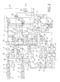
- the block diagram in Figure 2 shows a device referred to as an impact sensor 1 for triggering a safety device, not shown, of a motor vehicle, e.g. an air cushion or a belt tensioner.
- the impact sensor 1 has two accelerometers 2 and 3, e.g. two piezoelectric sensors, each with a directional sensitivity axis, which is designated A1 and A2 in FIG. 1.
- the sensitivity axes are set at an angle + or - against the longitudinal axis of a motor vehicle 4, the direction of travel of which is indicated by the arrow P. In this case the angle is 45 °.
- Accelerometers 2 and 3 each respond in a region around these sensitivity axes in accordance with a cosine characteristic, this region being identified by the four circles in FIG. 1.
- the output signals of the two accelerometers 2 and 3 are evaluated in signal channels 5 and 6 of the same structure. Only the signal channel 5 for the accelerometer 2 is described below:
- the output signal of the accelerometer 2 is amplified in an amplifier 7, shaped in a filter 8 and its amplitude is limited in an asymmetrical limiter 9 above a positive amplitude Sal and below a negative amplitude Sa2.
- a reference value Sa3 which is supplied by a reference value transmitter 11, is subtracted from the output signal obtained in this way, which corresponds to an acceleration of the sensor 2, in a differential element 10.
- the output signal of the differential element 10 is fed to an integrator 12 and in integrated into this.
- the output of the integrator 12, the signal of which corresponds to a speed, is connected to a threshold circuit 13 with two threshold switches 13 and 14 lying in parallel with a relatively low threshold value Sv2 and a second higher threshold value Sv3.
- the two threshold values are selected such that when the integrated output signal exceeds them, the safety device can be triggered under certain conditions. Which of the two threshold values is to act at the moment or whether the triggering of the safety device is to be blocked is decided by an evaluation circuit described below.
- the output of the threshold switch 13 is connected via an input line L1 to a trigger circuit constructed as a logic gate circuit 15.
- the output signal of the threshold switch 14 is combined with signals from the evaluation circuit, as explained further below.
- the said evaluation circuit is composed of several subcircuits, namely a response circuit, a start and selection circuit, two acceleration evaluation circuits, a rear impact evaluation circuit and a so-called hammer blow evaluation circuit.
- the response circuit is intended to ensure that the safety device is only triggered when there are significant signals in both signal channels 5 and 6, from which at least the possibility of a front or angled impact from the front can be concluded. For this purpose, signals in both signal channels must be linked together.
- a third threshold switch 21 is connected to a threshold value Svl, this threshold value being less than the lowest threshold value which triggers the safety device, ie lower than Sv2.
- This third threshold switch 21 is followed by a pulse extender 22, which extends the output signal of the threshold switch 21 to a time period St1.
- the signal channel 5 is linked to the signal channel 6, so that here the integrator 12 of the first signal channel 5 is connected to a threshold switch 21 'with the threshold value Sv1 and the same arrangement of a pulse extender 22' and an AND gate 23 ' .
- the input lines for the gate circuit 15, which carry signals generated in the same way, are labeled L2 'and L6'.
- the start of an impact of the vehicle is determined and one of the threshold values is also selected.
- the outputs of the integrators 12 and 12 ' are each connected to a threshold switch 31 and 31', each of which has the threshold value Sv4.
- This threshold is set in the range between the threshold Svl and Sv2, ie it is also lower than that for an off solution of the safety device suitable lowest threshold value Sv2.
- Both threshold switches 31, 31 ' are each followed by a pulse extender 32 or 32', which extend the pulse emitted by the associated threshold switch by a certain period of time St3.
- the outputs of these pulse extenders are connected to the two inputs of an AND gate 33, the output of which is connected to an edge-controlled timer 34, which emits a signal after a period of time St2 after activation.
- the output of the timer 34 is fed to an input of an OR gate 35, which in turn is followed by a resettable FLIP-FLOP 36.
- An input line L5 leading to the gate circuit 15 is connected to its output.
- the output of the AND gate 33 is also connected to an input of the OR gate 37 and its output to the inputs of two timing elements 38 and 39, respectively.
- the output signal of the timing element 38 is a HIGH signal when there is no activation, but it drops to a LOW signal after activation after a very short period of time St7.
- the output signals of this timer are fed to the gate circuit 15 via an input line L7.
- the second timing element 39 serves as a reset element for the timing element 38 and the FLIP-FLOP 36. After a relatively long period of time after activation, this timing element 39 emits a reset signal to the timing element 38 and the FLIP-FLOP 36 and sets them in their respective initial state back. This period is longer than the total operating time of the safety device in the event of an impact.
- the outputs of the differential elements 10 and 10 ' are each connected to two threshold switches 41 and 51 or 41' and 51 ', the threshold values of which are Sa4 and Sa5, respectively. These threshold values are chosen such that they are practically only reached in the event of an impact.
- the outputs of the two threshold switches 41 and 41 ' are connected to the inputs of the two pulse extenders 42 and 42'. Their outputs are connected to the two inputs of an AND gate 43 and its output is connected to an input of the OR gate 44.
- the outputs of the two threshold switches 51 and 51 ' are connected to the two inputs of an OR gate 52 and its output is connected to a pulse extender 53 which adjusts the output signal of the OR gate 52 to a time period St5. This time period is thus the same as the time period of the pulse extender 42 or 42 '. However, this condition does not have to be met.
- the output of the pulse extender 53 is fed to the second input of the mentioned OR gate 44, to the output of which an input line L3 for the gate circuit 15 is connected.
- This circuit is intended to prevent the passive safety device from being triggered in the event of a rear-end collision.
- the outputs of the asymmetrical limiter 9 and 9 ' are each guided to the input of an inverting amplifier 61 or 61', so that the negative output signals of the accelerometers 2 and 3 occurring in a rear-end collision are converted to positive signals.
- Each inverting amplifier 61, 61 ' is followed by a differential element 62 or 62' tet, with which a reference value transmitter 63 or 63 'is connected.
- a reference value transmitter 63 or 63 ' is connected.
- the signals are then integrated in an integrator 64 or 64 ', which is followed by a threshold switch 65 or 65' with a threshold value Sv5.
- the signals are therefore evaluated according to the same principle as in the signal channels 5 and 6.
- the output of the OR gate 66 is connected on the one hand to an input line L8 leading to the gate circuit 15 and on the other hand to a pulse length doubler 67 which doubles the pulse length, however, always emits a pulse of at least a minimum duration when activated.
- the output of this pulse length doubler is connected to an input line L4 which also leads to the gate circuit 15.
- This circuit is intended to prevent the passive safety device from being triggered in the workshop in the event of a short-term mechanical load, for example in the event of a hammer blow.
- the outputs of the unbalanced limiters 9 and 9 ' are each connected to the input of a holding and sampling circuit 71 and 71', in which within a short period St9 the end value reached at the end of this period with the previous minimum within this period Value is compared.
- the output signals of these sample and hold circuits are each fed to a threshold switch and compared there with a threshold Sa6.
- the outputs of the threshold switches 72 and 72 ' are linked together in an OR gate 73, the output of which is connected to the second input of the above OR gate 37 is connected.
- the output of the OR gate 73 is also led to an input of an AND gate 74, at the second input of which the output signal of the timing element 38 is present.
- the output of the AND gate 74 is connected to the second input of the OR gate 35.
- the gate circuit 15 serving as a trigger circuit for the passive safety device has two AND gates 81 and 81 'with five inputs, an OR gate 82 with four inputs linking the outputs of the AND gates 81 and 81' and a circuit breaker for the passive safety device leading AND gate 83 with three inputs.
- the AND gate 81 With the five inputs of the AND gate 81, the input lines L1, L2, L3, L4 and L5 are connected, with the five inputs of the second AND gate 81 'the input lines L1', L2 ', L3, L4 and L5.
- the four inputs for the OR gate 82 are at the respective output of the AND gates 81 and 81 ', the other two inputs are connected to the input lines L6 and L6'.
- One input of the AND gate 83 is connected to the output of the OR gate 82, the other two inputs to the input lines L7 and L8, the signals carried thereon being inverted in the AND gate 83.
- the accelerometer 2 emits a signal which exceeds the reference value Sa3 and is thus integrated in the integrator 12. If the integrated signal exceeds the threshold Sv2, there is a HIGH signal at the first input of the AND gate 81. However, the AND gate 81 only switches on and thus triggers the safety device, even if a HIGH signal is also present at the other four inputs and, furthermore, the two input lines L7 and L8 connected to the AND gate 83 carry a LOW signal.
- the A Gear line L2 only carries a HIGH signal during the period St1 after triggering the pulse extender 22, ie only when the integrated signals in both signal channels 5 and 6 reach the low threshold Sv1 and thus both accelerometers 2 and 3 receive a significant signal. If the threshold value Sv1 is not reached in only one channel, the AND gate 81 cannot switch through either. Such a case can occur, for example, if there is a side impact.
- the AND gate 81 can also only turn on when the input line L3 carries a HIGH signal. This means that at least one of the two acceleration evaluation circuits must output an output signal, i.e. either that the lower acceleration threshold Sa4 has been reached in both channels or that the higher acceleration threshold Sa5 has been exceeded in at least one channel.
- the fourth input line L4 only carries a HIGH signal if no rear impact has been detected in the rear impact assessment circuit, i.e. only if there is no signal at the input of the inverting pulse length doubler 67.
- the input signal of the pulse length doubler is also on line L8, so that the LOW signal enables the third input of AND gate 83. If a rear-end collision were detected, the output signal of the inverting pulse length doubler became a LOW signal, so that the AND gate 81 is not released. Likewise, the AND gate 83 would then be blocked by the HIGH signal at the output of the OR gate 66 through the inversion.
- the signal on input line L5 must be a HIGH signal. With the flip-flop 36, this is always the case in the event of an impact, during that with the timing element 34 predetermined time period St2. The prerequisite here is that the integrated signals in both signal channels 5 and 6 reach the threshold value Sv4, that is, significant signals must be present in both channels for the AND gate 81 to be switched through.
- the signal on the input line L7 must then be a LOW signal, ie after the start of an impact, which is detected by an output signal from the AND gate 33, the time period St7 must first have elapsed. During this period, the output signal of the pulse extender 38, which is usually LOW, switches to HIGH and thus blocks the AND gate 83 for this period. This blocking effect is also achieved if only a short hammer blow pulse is detected.
- the AND gate 81 is blocked by the flip-flop 36 via the input line L5 which now carries a LOW signal.
- the safety device can only be triggered if a HIGH signal is present at the OR gate 82 via the line L6 and the two input lines L7 and L8 carry a LOW signal.
- a HIGH signal on the input line L6 only occurs, however, if there is also a HIGH signal at both inputs of the AND gate 23, that is to say if the integrated output signal of the integrator 12 exceeds the threshold value Sv3 of the threshold value switch 14 and at the same time within that by the Pulse extender 22 predetermined time period St1 the integrated output signal of the integrator 12 'exceeds the low threshold Sv1. Also in this Traps must therefore have significant signals in both channels.
- the AND gate 81 can also be blocked during the time period St2 predetermined by the pulse extender 34, so that the passive safety device can only be triggered via the OR gate 82.
- the AND gate 81 is blocked by the LOW signal on the input line L2. Likewise, blocking can take place if no relevant output signal occurs in the acceleration evaluation circuits either at the output of the AND gate 43 or at the output of the pulse extender 53.
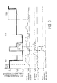
- FIG. 3 A schematic representation of the possible threshold value changes is shown in FIG. 3.
- the two threshold values Sv2 and Sv3 suitable for triggering the passive safety device are indicated, and the symbol also indicates the blocking of the entire device.
- This lock is always given during normal driving, since the AND gates 81 and 81 ', the OR gate 82 and the AND gate 83 are locked in the gate circuit.
- 3 is on the abscissa of the individual signal diagrams Time entered. At time zero, an impact is detected in the AND gate 33, since the integrated output signals in the signal channels 5 and 6 exceed the threshold value Sv4 predetermined by the threshold switches 31 and 31 '.
- the second line of the signal diagram in FIG. 3 only the integrated output signal of a signal channel is shown.
- the impact sensor 1 After detection of the zero point, the impact sensor 1 remains blocked for the short period of time St7 predetermined by the timer 38, since the associated input line L7 carries a HIGH signal during this period and the AND gate 83 blocks. Only after this release does one of the two threshold values Sv2 or Sv3 take effect, depending on the criteria specified above. In this case, it is assumed that the threshold Sv3 takes effect.
- the high acceleration threshold Sa5 is exceeded in the impact sensor 1 in one of the signal channels, which is shown in the third line of the signal diagram in FIG. 3, as a result of which the effective threshold is set to the threshold value Sv2.
- the threshold value is raised to, ie the entire collision sensor is blocked. This is done for the duration of the pulse delivered by the OR gate 66.
- the threshold value is then lowered to the larger threshold value Sv3, since the output signal of the pulse length doubler 67 blocks the two AND gates 81 and 81 'in the gate circuit 15.
- the higher threshold value Sv3 becomes effective for the impact sensor. If the integrated output signal in the signal channels 5 and 6 falls below the threshold value Sv4, then after the period St8, the entire impact sensor is replaced by the inverse Tiert reset signal of the timer 39 in the initial state.
- the course of the threshold values in the top line in FIG. 3 does not correspond to the actual course, in particular not during an impact, but only serves to demonstrate the switching options between the individual thresholds.
- a variety of other combinations are possible.
- the circuit described for the impact sensor can also be implemented differently.
Abstract
Description
Die Erfindung bezieht sich auf eine Einrichtung zur Auslösung einer passiven Sicherheitseinrichtung in Fahrzeugen gemäß dem Oberbegriff des ersten Patentanspruches.The invention relates to a device for triggering a passive safety device in vehicles according to the preamble of the first claim.
In der DE-OS 37 17 427 sind zwei Beschleunigungsaufnehmer (1 und 2) zusätzlich mit je einer Beschleunigungsbewertungsschaltung (13, 14 bzw. 16, 15) verbunden. Dabei weisen die Beschleunigungsbewertungsschaltungen jeweils zwei verschiedene Schwellwerte (Ref. 1 und Ref. 2) auf und beide Schwellwerte werden bei einem kritischen Aufprall des Fahrzeuges erreicht.In DE-OS 37 17 427 two accelerometers (1 and 2) are additionally connected to an acceleration evaluation circuit (13, 14 and 16, 15). The acceleration evaluation circuits each have two different threshold values (Ref. 1 and Ref. 2) and both threshold values are reached in the event of a critical impact by the vehicle.
Außerdem werden die Ausgänge dieser Bewertungsschaltungen (13, 14) über ein Oder-Gatter (19) mit einer Steuerschaltung (Auslöseschaltung für die Sicherheitsvorrichtung) verbunden.In addition, the outputs of these evaluation circuits (13, 14) are connected via an OR gate (19) to a control circuit (trigger circuit for the safety device).
Es ist wichtig, daß bei für die Auslösung ausreichenden ersten und zweiten Schwellwerten ein Heck- bzw. Seitenaufprall von einem Frontal- oder Schrägaufprall eindeutig unterschieden werden kann. Nur bei den beiden letzteren Aufprallarten werden auch die niedrigen zweiten Schwellenwerte in beiden Kanälen überschritten. Erst dann wird die Sicherheitseinrichtung ausgelöst. Bei einem Heck- bzw. Seitenaufprall werden die niedrigen zweiten Schwellenwerte zumindest in einem Kanal nicht überschritten, so daß dann auch nicht die Sicherheitseinrichtung ausgelöst wird.It is important that when the first and second threshold values are sufficient for triggering, a rear or side impact can be clearly distinguished from a front or oblique impact. Only in the latter two types of impact are the low second threshold values in both channels exceeded. Only then is the safety device triggered. With a rear or Side impact, the low second threshold values are not exceeded at least in one channel, so that the safety device is then not triggered either.
Neben der Unterscheidung zwischen unterschiedlichen Aufprallarten ist es mit dieser bekannten Einrichtung auch möglich, die konstruktive Ausbildung unterschiedlicher Fahrzeugtypen insbesondere im Bereich der Knautschzonen zu berücksichtigen, so daß für jeden Fahrzeugtyp bei einem kritischen Aufprall die Sicherheitseinrichtung zuverlässig ausgelöst wird.In addition to the differentiation between different types of impact, this known device also makes it possible to take into account the design of different types of vehicles, in particular in the area of the crumple zones, so that the safety device is reliably triggered for each type of vehicle in the event of a critical impact.
Der Erfindung liegt die Aufgabe zugrunde, eine Einrichtung der in Rede stehenden Art zu verbessern, um einerseits zuverlässig unterschiedliche Aufprallarten unterscheiden und andererseits die Einrichtung auch an unterschiedliche Fahrzustände des Fahrzeuges anpassen zu können.The invention is based on the object of improving a device of the type in question, on the one hand to reliably differentiate between different types of impact and on the other hand to be able to adapt the device to different driving conditions of the vehicle.
Diese Aufgabe ist gemäß der Erfindung durch die im kennzeichnenden Teil des Patentanspruches angegebenen Merkmale gelöst.This object is achieved according to the invention by the features specified in the characterizing part of the patent claim.
Demgemäß wird eine verfeinerte Logik vorgeschlagen, mit der die Ausgangssignale der einzelnen Signalkanäle in vielfältiger Hinsicht bewertet werden können. In jedem Signalkanal sind in jeder Schwellenwertschaltung mehrere Schwellenwertschalter mit unterschiedlichen Schwellenwerten vorgesehen, wobei diese Schwellenwerte so gewählt sind, daß eine Auslösung der Sicherheitseinrichtung bei unterschiedlichen Fahrsituationen möglich ist. Welcher der Schwellenwertschalter tatsächlich die Auslösung bewirkt, wird in einer Bewertungsschaltung und einer Logik ermittelt, mit deren Hilfe Signale aller Kanäle bewertet und aufgrund dieser Bewertung Sperr- und Freigabesignale abgegeben werden, die dann einen bestimmten Signalweg innerhalb der Einrichtung bis zum Leistungsschalter der Sicherheitseinrichtung freigeben bzw. sperren.Accordingly, a refined logic is proposed with which the output signals of the individual signal channels can be evaluated in a variety of ways. In each signal channel, several threshold value switches with different threshold values are provided in each threshold value circuit, these threshold values being selected so that the safety device can be triggered in different driving situations. Which of the threshold switches actually triggers is determined in an evaluation circuit and a logic with the aid of which signals from all channels are evaluated and, based on this evaluation, blocking and release signals are emitted, which then release or release a specific signal path within the device up to the circuit breaker of the safety device . lock.
Eine praxisgerechte Lösung erzielt man mit zwei Signalkanälen mit jeweils einem Beschleunigungsaufnehmer, wobei die Empfindlichkeitsachsen der Beschleunigungsaufnehmer in einer horizontalen Ebene in bezug zu der Kraftfahrzeuglängsachse unter entgegengesetzt gleichen Winkeln ausgerichtet sind.A practical solution is achieved with two signal channels, each with an accelerometer, the sensitivity axes of the accelerometers being aligned in opposite directions at the same angle in a horizontal plane with respect to the longitudinal axis of the motor vehicle.
Die einzelnen Signalkanäle weisen als Auswerteschaltung vorzugsweise eine einfache oder doppelte Integratorschaltung auf und sind bevorzugt mit jeweils zwei Schwellenwertschaltern ausgerüstet, wobei der eine Schwellenwert relativ niedrig und der andere Schwellenwert relativ hoch angesetzt ist. In der Bewertungsschaltung wird dann festgelegt, welcher dieser beiden Schwellenwerte für eine etwaige Auslösung der Sicherheitseinrichtung herangezogen werden soll. In der Bewertungsschaltung werden hierfür die aufintegrierten Signale in den einzelnen Kanälen und/oder die Ausgangssignale der Beschleunigungsaufnehmer direkt, gegebenenfalls nach einer Glättung und Signalformung verwendet. Diese Bewertung ermöglicht eine eindeutige Erkennung, ob die Ausgangssignale der Beschleunigungsaufnehmer einem Aufprall zuzuordnen sind oder durch andere Umstände bedingt sind. Letzteres kann z.B. der Fall sein, wenn das Fahrzeug über eine ausgesprochen schlechte Wegstrecke, durch Schlaglöcher, über eine Bordsteinkante oder dergleichen fährt. Ebenfalls können Situationen erkannt werden, in denen der Beschleunigungsaufnehmer kurzfristig so hoch mechanisch belastet wird, z.B. bei einem Hammerschlag, daß ohne eine Bewertung die Sicherheitseinrichtung ausgelöst würde. Dieses muß jedoch in jedem Falle verhindert werden.The individual signal channels preferably have a single or double integrator circuit as the evaluation circuit and are preferably equipped with two threshold value switches, one threshold value being set relatively low and the other threshold value being set relatively high. The evaluation circuit then determines which of these two threshold values should be used for a possible triggering of the safety device. For this purpose, the integrated signals in the individual channels and / or the output signals of the accelerometers are used directly in the evaluation circuit, possibly after smoothing and signal shaping. This evaluation enables a clear identification of whether the output signals of the accelerometers are to be assigned to an impact or are due to other circumstances. The latter can e.g. be the case when the vehicle is traveling over an extremely poor distance, through potholes, over a curb or the like. Situations can also be identified in which the accelerometer is subjected to such high mechanical loads for a short time, e.g. in the event of a hammer blow that the safety device would be triggered without an evaluation. However, this must be prevented in any case.
Die Bewertungsschaltung kann z.B. eine UND-Verknüpfung enthalten, in der die Ausgangssignale der Beschleunigungsaufnehmer unabhängig voneinander mit einem relativ niedrigen Schwellenwert verglichen werden und/oder eine ODER-Verknüpfung, in der die Ausgangssignale der Beschleunigungsaufnehmer unabhangig voneinander mit einem relativ hohen Schwellenwert verglichen werden. Wird in einem der Vergleiche ein Ausgangssignal nach den logischen Verknüpfungsgattern erzeugt, so werden z.B. in der Logik diejenigen Eingänge freigegeben, die den Schwellenwertschaltern mit einem niedrigen Schwellenwert in den einzelnen Signalkanälen zugeordnet sind.The evaluation circuit can contain, for example, an AND link in which the output signals of the accelerometers are independent of one another with a relatively low threshold value are compared and / or an OR operation in which the output signals of the accelerometers are compared independently of one another with a relatively high threshold value. If, in one of the comparisons, an output signal is generated according to the logic logic gates, the inputs that are assigned to the threshold value switches with a low threshold value in the individual signal channels are enabled in the logic, for example.
Zur eindeutigen Definition des zeitlichen Beginns eines Aufpralls werden bevorzugt die bereits aufintegrierten Signale der einzelnen Signalkanäle unabhängig voneinander einem Schwellenwertschalter mit jeweils nachgeschaltetem Impulsverlängerungsglied zugeführt. Die Ausgänge der Impulsverlängerungsglieder werden mit einer Vergleichs- und Zeitschaltung verbunden, die für eine bestimmte Zeit nach Beginn des Aufpralls die Eingänge der Logik, die den Schwellenwertschaltern mit niedrigen Schwellenwerten zugeordnet sind, freigeben und anschliessend sperren, so daß dann nur noch die Ausgangssignale der Schwellenwertschalter mit höheren Schwellenwerten berücksichtigt werden.In order to clearly define the time at which an impact begins, the signals of the individual signal channels which have already been integrated are preferably fed independently of one another to a threshold value switch, each with a pulse extension element connected downstream. The outputs of the pulse extension elements are connected to a comparison and time circuit which, for a certain time after the start of the impact, enables the inputs of the logic assigned to the threshold switches with low threshold values and then blocks them, so that then only the output signals of the threshold switches with higher threshold values.
Die Ausgangssignale der Beschleunigungsaufnehmer können auch dazu herangezogen werden, eindeutig einen Heckaufprall oder etwa einen Hammerschlag zu erkennen. Im ersten Fall werden die Signale der Beschleunigungsaufnehmer nach Invertierung jeweils über eine Integratorschaltung geführt. Die Ausgangssignale dieser Integratorschaltungen werden in einem gemeinsamen ODER-Glied zusammengefaßt, dessen Ausgangssignal den Leistungsschalter für die Auslösung der Sicherheitseinrichtung bei einem Heckaufprall sperrt. Im zweiten Fall werden die Ausgangssignale eines jeden Beschleunigungsaufnehmers in kurzen Zeitabständen abgetastet, wobei jeweils der momentane Wert am Ende eines solchen Zeitintervalles mit dem innerhalb dieses Zeitintervalles aufgetretenen Minimalwert verglichen wird. Werden bei diesem Vergleich hohe Differenzen festgestellt, so wird in einer Zeitschaltung überprüft, ob diese hohen Differenzen innerhalb eines bestimmten Zeitintervalls auftreten, was auf eine mechanische, nicht durch einen Aufprall verursachte Belastung des Beschleunigungsaufnehmers schließen läßt. In diesem Falle wird ebenfalls der Leistungsschalter für die Sicherheitseinrichtung gesperrt.The output signals of the accelerometers can also be used to clearly identify a rear impact or a hammer blow, for example. In the first case, the signals from the accelerometers are inverted via an integrator circuit. The output signals of these integrator circuits are combined in a common OR gate, the output signal of which blocks the circuit breaker for triggering the safety device in the event of a rear-end collision. In the second case, the output signals of each accelerometer are sampled at short time intervals, the instantaneous value at the end of such a time interval is compared with the minimum value that occurred within this time interval. If high differences are found in this comparison, a time circuit is used to check whether these high differences occur within a certain time interval, which indicates a mechanical load on the accelerometer that is not caused by an impact. In this case, the circuit breaker for the safety device is also blocked.
Mit einer Einrichtung gemäß der Erfindung kann der momentane, für eine Auslösung der Sicherheitseinrichtung wirksame Schwellenwert immer so ausgewählt werden, daß bei einem Aufprall des Fahrzeuges, bei dem die Sicherheitseinrichtung zum Schutz der Fahrzeuginsassen ausgelöst werden muß, diese zum frühest möglichen Zeitpunkt ausgelöst wird, in anderen Situationen jedoch gesperrt gehalten wird. Die Anpassungsfähigkeit der Einrichtung an unterschiedliche Fahrzeugtypen, unterschiedliche Fahrsituationen und unterschiedliche Aufprallarten kann auf diese Weise optimiert werden.With a device according to the invention, the instantaneous threshold value which is effective for triggering the safety device can always be selected such that in the event of a collision of the vehicle in which the safety device must be triggered to protect the vehicle occupants, it is triggered at the earliest possible time in is locked in other situations. The adaptability of the device to different vehicle types, different driving situations and different types of impacts can be optimized in this way.
Weitere Ausgestaltungen der Erfindung gehen aus den Unteransprüchen hervor. Die Erfindung ist in einem Ausführungsbeispiel anhand der Zeichnung näher erläutert. In dieser stellen dar:
Figur 1 schematisch den Einbau zweier Beschleunigungsaufnehmer mit unterschiedlich gerichteten Empfindlichkeitsachsen in einem Kraftfahrzeug;Figur 2 ein Blockschaltbild einer Einrichtung zum Auslösen einer passiven Sicherheitseinrichtung gemäß der Erfindung, die zwei gemäßFigur 1 angeordnete Beschleunigungsaufnehmer aufweist undFigur 3 mehrere Signaldiagramme, die den Verlauf von Parametern innerhalb der Schaltung gemäßFigur 2 darstellen.
- Figure 1 shows schematically the installation of two accelerometers with differently oriented sensitivity axes in a motor vehicle;
- Figure 2 is a block diagram of a device for triggering a passive safety device according to the invention, which has two accelerometers arranged according to Figure 1 and
- Figure 3 shows several signal diagrams that show the course of parameters within the circuit of Figure 2.
Das Blockschaltbild in Figur 2 zeigt eine als Aufprallsensor 1 bezeichnete Einrichtung zum Auslösen einer nicht dargestellten Sicherheitseinrichtung eines Kraftfahrzeuges, z.B. eines Luftkissens oder einer Gurtstrammereinrichtung. Der Aufprallsensor 1 weist zwei Beschleunigungsaufnehmer 2 und 3 auf, z.B. zwei Piezoaufnehmer mit jeweils einer gerichteten Empfindlichkeitsachse, die in Figur 1 mit A1 bzw. A2 bezeichnet ist. Wie aus Figur 1 hervorgeht, sind die Empfindlichkeitsachsen mit einem Winkel + bzw. - gegen die Längsachse eines Kraftfahrzeugs 4 angestellt, dessen Fahrtrichtung mit dem Pfeil P bezeichnet ist. Der Winkel beträgt in diesem Falle 45°. Die Beschleunigungsaufnehmer 2 und 3 sprechen jeweils in einem Bereich um diese Empfindlichkeitsachsen entsprechend einer Kosinus- -Charakteristik an, wobei dieser Bereich in Figur 1 durch die vier Kreise gekennzeichnet ist.The block diagram in Figure 2 shows a device referred to as an
Die Ausgangssignale der beiden Beschleunigungsaufnehmer 2 und 3 werden in gleich aufgebauten Signalkanälen 5 bzw. 6 ausgewertet. Lediglich der Signalkanal 5 für den Beschleunigungsaufnehmer 2 wird im folgenden beschrieben:The output signals of the two
Das Ausgangssignal des Beschleunigungsaufnehmers 2 wird in einem Verstärker 7 verstärkt, in einem Filter 8 geformt und in seiner Amplitude in einem unsymmetrischen Begrenzer 9 oberhalb einer positiven Amplitude Sal und unterhalb einer negativen Amplitude Sa2 begrenzt. Von dem derart gewonnenen Ausgangssignal, das einer Beschleunigung des Aufnehmers 2 entspricht, wird in einem Differenzglied 10 ein Referenzwert Sa3 abgezogen, der von einem Referenzwertgeber 11 geliefert wird. Das Ausgangssignal des Differenzgliedes 10 wird einem Integrator 12 zugeführt und in diesem aufintegriert. Der Ausgang des Integrators 12, dessen Signal einer Geschwindigkeit entspricht, wird mit einer Schwellenwertschaltung 13 mit zwei parallel liegenden Schwellenwertschaltern 13 und 14 mit einem relativ niedrigen Schwellenwert Sv2 bzw. einem zweiten höheren Schwellenwert Sv3 verbunden. Diese beiden Schwellenwerte sind so gewählt, daß dann , wenn sie von dem integrierten Ausgangssignal überschritten werden, eine Auslösung der Sicherheitseinrichtung unter bestimmten Bedingungen möglich ist. Welcher der beiden Schwellenwerte momentan wirken soll oder ob die Auslösung der Sicherheitseinrichtung gesperrt werden soll, wird durch eine weiter unten beschriebene Bewertungsschaltung entschieden. Der Ausgang des Schwellenwertschalters 13 ist über eine Eingangsleitung L1 mit einer als logische Gatterschaltung 15 aufgebauten Auslöseschaltung verbunden. Das Ausgangssignal des Schwellenwertschalters 14 wird mit Signalen der Bewertungsschaltung verknüpft, wie weiter unten erläutert.The output signal of the
Die genannten gleichartigen Bauelemente des zweiten Signalkanales 6 für den zweiten Beschleunigungsaufnehmer 3 sind mit den gleichen Bezugszeichen wie oben gekennzeichnet, denen jedoch ein (′) hinzugefügt ist.The aforementioned similar components of the
Die genannte Bewertungsschaltung setzt sich aus mehreren Teilschaltungen zusammen, nämlich einer Ansprechschaltung, einer Start- und Auswahlschaltung, zwei Beschleunigungsbewertungsschaltungen, einer Heckaufprall-Bewertungsschaltung und einer sogenannten Hammerschlag-Bewertungsschaltung.The said evaluation circuit is composed of several subcircuits, namely a response circuit, a start and selection circuit, two acceleration evaluation circuits, a rear impact evaluation circuit and a so-called hammer blow evaluation circuit.
Die Ansprechschaltung soll gewährleisten, daß die Sicherheitseinrichtung nur dann ausgelöst wird, wenn in beiden Signalkanälen 5 und 6 signifikante Signale vorliegen, aus denen zumindest auf die Möglichkeit eines Front- oder Schrägaufpralls von vorne geschlossen werden kann. Hierzu müssen Signale in beiden Signalkanälen miteinander verknüpft werden. Mit dem Ausgang des Integrators 12′ ist ein dritter Schwellenwertschalter 21 mit einem Schwellenwert Svl verbunden, wobei dieser Schwellenwert kleiner als der niedrigste zu einer Auslösung der Sicherheitseinrichtung führende Schwellenwert ist, d.h. niedriger als Sv2. Diesem dritten Schwellenwertschalter 21 ist ein Impulsverlängerer 22 nachgeschaltet, der das Ausgangssignal des Schwellenwertschalters 21 auf eine Zeitspanne St1 verlängert. Der Ausgang des Impulsverlängerers 22 ist über eine Eingangsleitung L2 mit der logischen Gatterschaltung verbunden, ebenso mit einem Eingang eines UND-Gatters , dessen zweitem Eingang das Ausgangssignal des Schwellwertschalters 14 zugeführt ist. Der Ausgang des UND-Gatters 23 ist über eine Eingangsleitung L6 mit der Gatterschaltung 15 verbunden.The response circuit is intended to ensure that the safety device is only triggered when there are significant signals in both
In gleicher Weise ist der Signalkanal 5 mit dem Signalkanal 6 verknüpft, so daß hier der Integrator 12 des ersten Signalkanales 5 mit einem Schwellenwertschalter 21′ mit dem Schwellenwert Sv1 und der gleichen Anordnung aus einem Impulsverlängerer 22′ und einem UND-Gatter 23′ verbunden ist. Die Eingangsleitungen für die Gatterschaltung 15, die auf die gleiche Art erzeugte Signale führen, sind mit L2′ und L6′ bezeichnet.In the same way, the
Mit dieser Schaltung wird der Beginn eines Aufpralls des Fahrzeuges festgestellt und außerdem einer der Schwellenwerte ausgewählt. Hierzu sind die Ausgänge der Integratoren 12 bzw. 12′ jeweils mit einem Schwellenwertschalter 31 bzw. 31′ verbunden, die jeweils den Schwellenwert Sv4 aufweisen. Dieser Schwellenwert wird im Bereich zwischen dem Schwellenwert Svl und Sv2 eingestellt, d.h. er liegt ebenfalls niedriger als der für eine Aus lösung der Sicherheitseinrichtung geeignete niedrigste Schwellenwert Sv2. Beiden Schwellenwertschaltern 31, 31′ ist je ein Impulsverlängerer 32 bzw. 32′ nachgeschaltet, die den vom zugeordneten Schwellenwertschalter abgegebenen Impuls um eine bestimmte Zeitspanne St3 verlängern. Die Ausgänge dieser Impulsverlängerer sind mit den beiden Eingängen eines UND-Gatters 33 verbunden, dessen Ausgang mit einem flankengesteuerten Zeitglied 34, das nach einer Zeitspanne St2 nach Ansteuerung ein Signal abgibt. Der Ausgang des Zeitgliedes 34 wird einem Eingang eines ODER-Gatters 35 zugeführt, dem seinerseits ein rücksetzbarer FLIP-FLOP 36 nachgeschaltet ist. Mit dessen Ausgang ist eine zu der Gatterschaltung 15 führende Eingangsleitung L5 verbunden.With this circuit the start of an impact of the vehicle is determined and one of the threshold values is also selected. For this purpose, the outputs of the
Der Ausgang des UND-Gatters 33 wird ferner mit einem Eingang des ODER-Gatters 37 und dessen Ausgang mit den Eingängen zweier Zeitglieder 38 bzw. 39 verbunden. Das Ausgangssignal des Zeitgliedes 38 ist bei fehlender Ansteuerung ein HOCH-Signal das jedoch bei Ansteuerung nach einer sehr kurzen Zeitspanne St7 auf ein NIEDRIG-Signal abfällt. Die Ausgangssignale dieses Zeitgliedes werden über eine Eingangsleitung L7 der Gatterschaltung 15 zugeführt. Das zweite Zeitglied 39 dient als Rücksetzglied für das Zeitglied 38 und den FLIP-FLOP 36. Dieses Zeitglied 39 gibt nach einer relativ langen Zeitspanne nach der Ansteuerung ein Rücksetzsignal an das Zeitglied 38 und den FLIP-FLOP 36 ab und setzt diese in ihren jeweiligen Ausgangszustand zurück. Diese Zeitspanne ist länger als die Gesamtfunktionsdauer der Sicherheitseinrichtung im Falle eines Aufpralls.The output of the AND
Diese beiden Schaltungen dienen dazu, aufgrund der Ausgangssignale der Beschleunigungsaufnehmer zuverlässig einen Aufprall des Fahrzeuges zu erkennen und von anderen Situationen zu unter scheiden sowie im Falle eines tatsächlichen Aufpralles auch einen entsprechenden Schwellenwert Sv2 bzw. Sv3 auszuwählen.These two circuits are used to reliably detect an impact of the vehicle on the basis of the output signals from the accelerometers and to prevent them from falling under other situations and in the event of an actual impact, also select a corresponding threshold value Sv2 or Sv3.
Die Ausgänge der Differenzglieder 10 bzw. 10′ sind jeweils mit zwei Schwellenwertschaltern 41 und 51 bzw. 41′ und 51′ verbunden, deren Schwellenwerte jeweils Sa4 und Sa5 betragen. Diese Schwellenwerte sind so gewählt, daß sie praktisch nur bei einem Aufprall erreicht werden. dieAusgänge der beiden Schwellwertschalter 41 und 41′ sind mit den Eingängen der beiden Impulsverlängerer 42 bzw. 42′ verbunden. Deren Ausgänge sind mit den beiden Eingängen eines UND-Gliedes 43 verbunden und dessen Ausgang mit einem Eingang des ODER-Gatters 44.The outputs of the
Die Ausgänge der beiden Schwellenwertschalter 51 bzw. 51′ sind mit den beiden Eingängen eines ODER-Gatters 52 und dessen Ausgang mit einem Impulsverlängerer 53 verbunden, der das Ausgangssignal des ODER-Gatters 52 auf eine Zeitspanne St5 einstellt. Diese Zeitspanne ist somit die gleiche wie die Zeitspanne der Impulsverlängerer 42 bzw. 42′. Diese Bedingung muß jedoch nicht erfüllt sein. Der Ausgang des Impulsverlängerers 53 wird auf den zweiten Eingang des erwähnten ODER-Gatters 44 geführt, mit dessem Ausgang eine Eingangsleitung L3 für die Gatterschaltung 15 verbunden ist.The outputs of the two
Mit dieser Schaltung soll die Auslösung der passiven Sicherheitseinrichtung bei einem Heckaufprall unterbunden werden. Hierzu sind die Ausgänge der unsymmetrischen Begrenzer 9 und 9′ jeweils auf den Eingang eines invertierenden Verstärkers 61 bzw. 61′ geführt, so daß die bei einem Heckaufprall auftretenden negativen Ausgangssignale der Beschleunigungsaufnehmer 2 und 3 zu positiven Signalen gewandelt werden. Jedem invertierenden Verstärker 61, 61′ ist ein Differenzglied 62 bzw. 62′ nachgeschal tet, mit denen jeweils ein Referenzwertgeber 63 bzw. 63′ verbunden ist. Durch diese Referenzwertgeber wird von dem Ausgangssignal der invertierenden Verstärker ein Betrag entsprechend der Schwelle Sa3 abgezogen, die demnach den gleichen Wert aufweist wie diejenige des Referenzwertgebers 11. Auch diese Bedingung ist nicht zwingend erforderlich. Anschließend erfolgt eine Integration der Signale in jeweils einem Integrator 64 bzw. 64′ denen ein Schwellenwertschalter 65 bzw. 65′ mit einem Schwellenwert Sv5 nachgeschaltet ist. Die Auswertung der Signale erfolgt demnach nach dem gleichen Prinzip wie in den Signalkanälen 5 und 6. Der Ausgang des ODER-Gatters 66 ist einmal mit einer zu der Gatterschaltung 15 führenden Eingangsleitung L8 und zum anderen mit einem Impulslängenverdoppler 67 verbunden, der die Impulslänge verdoppelt, jedoch bei einer Ansteuerung immer einen Impuls zumindest minimaler Zeitdauer abgibt. Der Ausgang dieses Impulslängenverdopplers ist mit einer ebenfalls zu der Gatterschaltung 15 führenden Eingangsleitung L4 verbunden.This circuit is intended to prevent the passive safety device from being triggered in the event of a rear-end collision. For this purpose, the outputs of the
Mit dieser Schaltung soll ausgeschlossen werden, daß bei einer kurzfristigen mechanischen Belastung der Beschleunigungsaufnehmer, z.B. bei einem Hammerschlag in der Werkstatt die passive Sicherheitseinrichtung ausgelöst wird. Hierzu sind wiederum die Ausgänge der unsymmetrischen Begrenzer 9 und 9′ jeweils mit dem Eingang einer Halte- und Abtastschaltung 71 bzw. 71′ verbunden, in denen innerhalb jeweils einer kurzen Zeitspanne St9 der am Ende dieser Zeitspanne erreichte Endwert mit dem innerhalb dieser Zeitspanne vorhergehenden minimalen Wert verglichen wird. Die Ausgangssignale dieser Abtast- und Halteschaltungen werden jeweils einem Schwellenwertschalter zugeführt und dort mit einer Schwelle Sa6 verglichen. Die Ausgänge der Schwellenwertschalter 72 und 72′ werden in einem ODER-Gatter 73 miteinander verknüpft, dessen Ausgang mit dem zweiten Eingang des oben erwähnten ODER-Gatters 37 verbunden ist. Der Ausgang des ODER-Gatters 73 ist ferner an einen Eingang eines UND-Gatters 74 geführt, an dessen zweitem Eingang das Ausgangssignal des Zeitgliedes 38 liegt. Der Ausgang des UND-Gatters 74 ist mit dem zweiten Eingang des ODER-Gatters 35 verbunden.This circuit is intended to prevent the passive safety device from being triggered in the workshop in the event of a short-term mechanical load, for example in the event of a hammer blow. For this purpose, the outputs of the
Die als Auslöseschaltung für die passive Sicherheitseinrichtung dienende Gatterschaltung 15 weist zwei UND-Tore 81 und 81′ mit fünf Eingängen, ein die Ausgänge der UND-Gatter 81 und 81′ verknüpfendes ODER-Gatter 82 mit vier Eingängen und ein zum Leistungsschalter für die passive Sicherheitseinrichtung führendes UND-Gatter 83 mit drei Eingängen auf. Mit den fünf Eingängen des UND-Gatters 81 sind die Eingangsleitungen L1, L2, L3, L4 und L5 verbunden, mit den fünf Eingängen des zweiten UND-Gatters 81′ die Eingangsleitungen L1′, L2′, L3, L4 und L5. Die vier Eingänge für das ODER-Gatter 82 liegen an dem jeweiligen Ausgang der UND-Gatter 81 und 81′ , die beiden anderen Eingänge sind mit den Eingangsleitungen L6 und L6′ verbunden. Der eine Eingang des UND-Gatters 83 ist mit dem Ausgang des ODER-Gattes 82 verbunden, die beiden anderen Eingänge mit den Eingangsleitungen L7 und L8, wobei die darauf geführten Signale im UND-Gatter 83 invertiert werden.The
Die Funktion der beschriebenen Schaltung ist nun folgende:The function of the circuit described is now as follows:
Es sei angenommen, daß der Beschleunigungsaufnehmer 2 ein Signal abgibt, das den Referenzwert Sa3 überschreitet und somit in dem Integrator 12 aufintegriert wird. Überschreitet das aufintegrierte Signal die Schwelle Sv2, dann liegt am ersten Eingang des UND-Tores 81 ein HOCH-Signal. Das UND-Tor 81 schaltet jedoch erst durch und löst damit die Sicherheitseinrichtung aus, wenn auch an den anderen vier Eingängen ein HOCH-Signal anliegt und ferner am UND-Gatter 83 die mit diesem verbundenen beiden Eingangsleitungen L7 und L8 ein NIEDRIG-Signal führen. Die Ein gangsleitung L2 führt nur während der Zeitspanne St1 nach Ansteuerung des Impulsverlängerers 22 ein HOCH-Signal, d.h. nur dann, wenn in beiden Signalkanälen 5 und 6 die aufintegrierten Signale die niedrige Schwelle Sv1 erreichen und somit beide Beschleunigungsaufnehmer 2 und 3 ein signifikantes Signal aufnehmen. Wird nur in einem Kanal der Schwellenwert Sv1 nicht erreicht, so kann auch das UND-Gatter 81 nicht durchschalten. Ein solcher Fall kann z.B. dann auftreten, wenn ein Seitenaufprall vorliegt.It is assumed that the
Das UND-Gatter 81 kann auch nur durchschalten, wenn die Eingangsleitung L3 ein HOCH-Signal führt. Dies bedeutet, daß zumindest eine der beiden Beschleunigungsbewertungsschaltungen ein Ausgangssignal abgeben muß, d.h. entweder, daß die niedrigere Beschleunigungsschwelle Sa4 in beiden Kanälen erreicht ist oder die höhere Beschleunigungsschwelle Sa5 zumindest in einem Kanal überschritten ist.The AND
Die vierte Eingangsleitung L4 führt nur dann ein HOCH-Signal, wenn in der Heckaufprall-Bewertungsschaltung kein Heckaufprall detektiert wurde, d.h. nur dann, wenn am Eingang des invertierenden Impulslängenverdopplers 67 kein Signal anliegt. Das Eingangssignal des Impulslängenverdopplers liegt auch auf der Leitung L8, so daß durch dieses NIEDRIG-Signal der dritte Eingang des UND-Gatters 83 freigegeben wird. Würde ein Heckaufprall detektiert, so wurde das Ausgangssignal des invertierenden Impulslängenverdopplers ein NIEDRIG-Signal, so daß das UND-Gatter 81 nicht freigegeben wird. Ebenso würde dann durch HOCH-Signal am Ausgang des ODER-Gatters 66 durch die Invertierung das UND-Gatter 83 gesperrt.The fourth input line L4 only carries a HIGH signal if no rear impact has been detected in the rear impact assessment circuit, i.e. only if there is no signal at the input of the inverting
Schließlich muß noch das auf der Eingangsleitung L5 anliegende Signal ein HOCH-Signal sein. Durch das Flip-Flop 36 ist dies bei einem Aufprall immer der Fall während der durch das Zeitglied 34 vorgegebenen Zeitspanne St2. Vorausgesetzt hierbei ist, daß in beiden Signalkanälen 5 und 6 die aufintegrierten Signale den Schwellenwert Sv4 erreichen, d.h. für eine Durchschaltung des UND-Gatters 81 müssen in beiden Kanälen signifikante Signale vorliegen. Außerdem muß dann noch das Signal auf der Eingangsleitung L7 ein NIEDRIG-Signal sein, d.h. nach Beginn eines Aufpralls, was durch ein Ausgangssignal des UND-Gatters 33 detektiert wird, muß erst die Zeitspanne St7 verstrichen sein. Während dieser Zeitspanne schaltet das üblicherweise auf NIEDRIG liegende Ausgangssignal des Impulsverlängerers 38 auf HOCH und sperrt damit für diese Zeitspanne das UND-Gatter 83. Diese Sperrwirkung wird auch erzielt, wenn lediglich ein kurzer Hammerschlagimpuls detektiert wird.Finally, the signal on input line L5 must be a HIGH signal. With the flip-
Erst wenn alle diese Bedingungen erfüllt sind, schaltet das UND-Gatter 81 durch, so daß dessen Ausgangssignal an den Ausgang A der Gatterschaltung hindurchgeleitet wird und die Auslösung der passiven Sicherheitseinrichtung bewirkt.Only when all of these conditions are met does the AND
Nach Ablauf der Zeitspanne St2, die durch das Zeitglied 34 vorgegeben wird, wird durch das Flip-Flop 36 das UND-Gatter 81 über die jetzt ein NIEDRIG-Signal führende Eingangsleitung L5 gesperrt. In diesem Falle kann die Sicherheitseinrichtung nur ausgelöst werden, wenn über die Leitung L6 ein HOCH-Signal an dem ODER-Gatter 82 anliegt und die beiden Eingangsleitungen L7 und L8 ein NIEDRIG-Signal führen. Ein HOCH-Signal auf der Eingangsleitung L6 tritt jedoch nur auf, wenn an beiden Eingängen des UND-Gatters 23 ebenfalls ein HOCH-Signal anliegt, d.h. wenn das aufintegrierte Ausgangssignal des Integrators 12 den Schwellenwert Sv3 des Schwellenwertschalters 14 übersteigt und gleichzeitig innerhalb der durch den Impulsverlängerer 22 vorgegebenen Zeitspanne St1 das aufintegrierte Ausgangssignal des Integrators 12′ die niedrige Schwelle Sv1 überschreitet. Auch in diesem Falle müssen demnach in beiden Kanälen signifikante Signale vorliegen.After the time period St2, which is predetermined by the
Auch während der durch den Impulsverlängerer 34 vorgegebenen Zeitspanne St2 kann das UND-Gatter 81 gesperrt werden, so daß die Auslösung der passiven Sicherheitseinrichtung nur über das ODER-Gatter 82 erfolgen kann. Das UND-Gatter 81 wird über das NIEDRIG-Signal auf der Eingangsleitung L2 gesperrt. Ebenso kann eine Sperrung dann erfolgen, wenn in den Beschleuniguns-Bewertungsschaltungen kein relevantes Ausgangssignal entweder am Ausgang des UND-Gatters 43 oder am Ausgang es Impulsverlängerers 53 auftritt.The AND
Die gleichen Überlegungen hinsichtlich des Durchschaltens des UND-Gatters 81 gelten auch für das zweite UND-Gatter 81′, da auf den Eingangsleitungen L1′ und L2′ in ähnlicher Weise wie auf den Eingangsleitungen L1 und L2 erzeugte Signale anliegen und die übrigen Leitungen L3, L4 und L5 für beide UND-Gatter 81 und 81′ gemeinsam sind.The same considerations regarding the switching through of the AND
Mit der beschriebenen Schaltung können somit eine Vielzahl von Ausgangssignalen der Beschleunigungsaufnehmer 2 und 3 bewertet und eindeutig für eine Auslösung bzw. Nichtauslösung der passiven Sicherheitseinrichtung herangezogen werden.With the circuit described, a large number of output signals of the
Eine schematische Darstellung der möglichen Schwellenwertumschaltungen ist in Figur 3 dargestellt. In der oberen Zeile sind die beiden zu einer Auslösung der passiven Sicherheitseinrichtung geeigneten Schwellenwerte Sv2 und Sv3 angegeben, außerdem ist mit dem Zeichen die Sperrung der gesamten Einrichtung gekennzeichnet. Diese Sperrung ist bei normalem Fahrbetrieb immer gegeben, da die UND-Gatter 81 und 81′, das ODER-Gatter 82 und das UND-Gatter 83 in der Gatterschaltung gesperrt sind. Auf der Abszisse der einzelnen Signaldiagramme in Figur 3 ist die Zeit eingetragen. Zum Zeitpunkt Null wird ein Aufprall im UND-Gatter 33 detektiert, da die aufintegrierten Ausgangssignale in den Signalkanälen 5 und 6 den durch die Schwellenwertschalter 31 und 31′ vorgegebenen Schwellenwert Sv4 überschreiten. In der zweiten Zeile des Signaldiagrammes in Figur 3 ist lediglich das aufintegrierte Ausgangssignal eines Signalkanals dargestellt. Der Aufprallsensor 1 bleibt nach der Detektierung des Nullpunktes noch während der durch das Zeitglied 38 vorgegebenen kurzen Zeitspanne St7 gesperrt, da während dieser Zeitspanne die damit verbundene Eingangsleitung L7 ein HOCH-Signal führt und das UND-Gatter 83 sperrt. Erst nach dieser Freigabe wird einer der beiden Schwellenwerte Sv2 bzw. Sv3 wirksam, je nach den oben angegebenen Kriterien. In diesem Falle ist angenommen, daß der Schwellenwert Sv3 wirksam wird. Zu einem anderen Zeitpunkt wird in dem Aufprallsensor 1 in einem der Signalkanäle die hohe Beschleunigungsschwelle Sa5 überschritten, was in der dritten Zeile des Signaldiagrammes in Figur 3 dargestellt ist, wodurch die wirksame Schwelle auf den Schwellenwert Sv2 eingestellt wird. Sollte dann ein Heckaufprall detektiert werden, d.h. die Schwelle SV5 in einem der Kanäle der Heckaufprall-Bewertungsschaltung überschritten werden, so wird der Schwellenwert auf angehoben, d.h. der gesamte Aufprallsensor gesperrt. Dies erfolgt während der Dauer des von dem ODER-Gatter 66 abgegebenen Impulses. Anschließend wird der Schwellenwert auf den größeren Schwellenwert Sv3 abgesenkt, da das Ausgangssignal des Impulslängenverdopplers 67 die beiden UND-Gatter 81 und 81′ in der Gatterschaltung 15 sperrt.A schematic representation of the possible threshold value changes is shown in FIG. 3. In the top line, the two threshold values Sv2 and Sv3 suitable for triggering the passive safety device are indicated, and the symbol also indicates the blocking of the entire device. This lock is always given during normal driving, since the AND
Ist die durch das Zeitglied 34 gegebene Zeitspanne St2 abgelaufen, dann wird für den Aufprallsensor der höhere Schwellenwert Sv3 wirksam. Fällt das aufintegrierte Ausgangssignal in den Signalkanälen 5 und 6 unter den Schwellenwert Sv4 , so wird nach der Zeitspanne St8 der gesamte Aufprallsensor durch das inver tierte Rücksetzsignal des Zeitgliedes 39 in den Ausgangszustand gesetzt.If the time period St2 given by the
Es sei darauf hingewiesen, daß der Verlauf der Schwellenwerte in der obersten Zeile in Figur 3 nicht dem tatsächlichen Verlauf, insbesondere nicht während eines Aufpralles entspricht, sondern nur zur Demonstration der Umschaltmöglichkeiten zwischen den einzelnen Schwellen dient. Eine Vielzahl von anderen Kombinationen ist möglich. Selbstverständlich kann die beschriebene Schaltung für den Auf- prallsensor auch anders realisiert werden. Außerdem ist es nicht notwendig, sämtliche angegebenen Teilschaltungen der Bewertungs- schaltung zu verwenden. Auch wenn in der angegebenen Schaltung diskrete Elemente aufgeführt sind, so sind diese Elemente im we- sentlichen durch die Funktion bestimmt. Eine Realisierung z.B. mit Hilfe eines Mikroprozessors liegt im Rahmen der Erfindung.It should be pointed out that the course of the threshold values in the top line in FIG. 3 does not correspond to the actual course, in particular not during an impact, but only serves to demonstrate the switching options between the individual thresholds. A variety of other combinations are possible. Of course, the circuit described for the impact sensor can also be implemented differently. In addition, it is not necessary to use all of the specified subcircuits of the evaluation circuit. Even if discrete elements are listed in the specified circuit, these elements are essentially determined by the function. A realization e.g. using a microprocessor is within the scope of the invention.
Claims (16)
Applications Claiming Priority (2)
| Application Number | Priority Date | Filing Date | Title |
|---|---|---|---|
| DE3816587A DE3816587A1 (en) | 1988-05-16 | 1988-05-16 | DEVICE FOR TRIGGERING A PASSIVE SAFETY DEVICE |
| DE3816587 | 1988-05-16 |
Publications (3)
| Publication Number | Publication Date |
|---|---|
| EP0342401A2 true EP0342401A2 (en) | 1989-11-23 |
| EP0342401A3 EP0342401A3 (en) | 1991-08-07 |
| EP0342401B1 EP0342401B1 (en) | 1994-03-30 |
Family
ID=6354433
Family Applications (1)
| Application Number | Title | Priority Date | Filing Date |
|---|---|---|---|
| EP89107534A Expired - Lifetime EP0342401B1 (en) | 1988-05-16 | 1989-04-26 | Device for triggering a passive safety system |
Country Status (4)
| Country | Link |
|---|---|
| US (1) | US5173614A (en) |
| EP (1) | EP0342401B1 (en) |
| JP (1) | JP2785133B2 (en) |
| DE (1) | DE3816587A1 (en) |
Cited By (12)
| Publication number | Priority date | Publication date | Assignee | Title |
|---|---|---|---|---|
| WO1990009298A1 (en) * | 1989-02-18 | 1990-08-23 | Robert Bosch Gmbh | Process for releasing restraining means |
| EP0531989A1 (en) * | 1991-09-11 | 1993-03-17 | Toyota Jidosha Kabushiki Kaisha | Side collision sensor system for side airbag apparatus |
| EP0693404A3 (en) * | 1994-07-21 | 1996-11-13 | Telefunken Microelectron | Method for deploying side air bags of a passive safety device in a motor vehicle |
| EP0748725A1 (en) * | 1995-06-15 | 1996-12-18 | Trw Inc. | Method and apparatus for providing a safing function for side impact crash sensing systems |
| US5692775A (en) * | 1994-12-22 | 1997-12-02 | Trw Inc. | Method and apparatus for controlling an occupant restraint system in response to selected criteria zone |
| WO1998018662A1 (en) * | 1996-10-31 | 1998-05-07 | Siemens Aktiengesellschaft | Control arrangement for a passenger-protection system to protect against side impact in a vehicle |
| USRE36122E (en) * | 1989-02-18 | 1999-03-02 | Robert Bosch Gmbh | Method for controlling the release of passenger restraint systems |
| US6460882B1 (en) | 1999-01-07 | 2002-10-08 | Siemens Vdo Automotive Corporation | Airbag actuation event discrimination system and method |
| EP1438216A1 (en) * | 2001-10-25 | 2004-07-21 | Bayerische Motoren Werke Aktiengesellschaft | Method for triggering a vehicle occupant restraint means |
| EP2045144A1 (en) * | 2007-10-02 | 2009-04-08 | Continental Automotive GmbH | Method for identifying the collision side in a frontal impact |
| CN103507735A (en) * | 2012-06-26 | 2014-01-15 | 罗伯特·博世有限公司 | A method and apparatus for detecting, diagnosing, and triggering a trigger means of a personal protection means |
| WO2018149663A1 (en) * | 2017-02-14 | 2018-08-23 | Robert Bosch Gmbh | Circuit arrangement for carrying out a comparison |
Families Citing this family (75)
| Publication number | Priority date | Publication date | Assignee | Title |
|---|---|---|---|---|
| US5483447A (en) * | 1988-09-17 | 1996-01-09 | Robert Bosch Gmbh | Apparatus for tripping a system for the protection of occupants of a vehicle |
| JP2768710B2 (en) * | 1988-09-17 | 1998-06-25 | ローベルト・ボッシュ・ゲゼルシャフト・ミット・ベシュレンクテル・ハフツング | A device that activates a protection device that protects a vehicle occupant |
| US5225985A (en) * | 1989-01-24 | 1993-07-06 | Diesel Kiki Co., Ltd. | Vehicle safety device actuating apparatus with adaptive reference level |
| DE3942011C3 (en) * | 1989-12-20 | 1996-10-17 | Telefunken Microelectron | Device for triggering a passive safety device for vehicle occupants |
| DE4005444A1 (en) * | 1990-02-21 | 1991-08-22 | Bayerische Motoren Werke Ag | METHOD AND DEVICE FOR SUPPORTING A DRIVER FOR A ROAD TRACK CHANGE |
| US5787377A (en) * | 1990-08-24 | 1998-07-28 | Kanto Seiki Co. Ltd. | Air-bag control circuit |
| DE4128230C2 (en) * | 1990-08-24 | 1997-01-09 | Kanto Seiki Co | Control system for an airbag installed in a motor vehicle |
| US6125313A (en) * | 1990-08-24 | 2000-09-26 | Kanto Seiki Co., Ltd. | Air-bag control circuit |
| DE4029195C2 (en) * | 1990-09-14 | 1996-09-26 | Telefunken Microelectron | Impact sensor |
| DE4116336C1 (en) * | 1991-05-18 | 1992-06-11 | Messerschmitt-Boelkow-Blohm Gmbh, 8012 Ottobrunn, De | Passive safety device release assembly for motor vehicle occupant - has acceleration pick=ups with sensitivity axes directed to detect angle of frontal impact and supplying evaluating circuit |
| DE4117811A1 (en) * | 1991-05-31 | 1992-12-03 | Messerschmitt Boelkow Blohm | Motor vehicle impact detection method for activating occupant safety system - measuring acceleration and deceleration, integrating, subtracting previous speed value and comparing with threshold |
| DE69205067T2 (en) * | 1991-06-07 | 1996-03-21 | Kansei Kk | Impact protection device for passengers in a motor vehicle or the like. |
| US6609053B1 (en) * | 1995-06-07 | 2003-08-19 | Automotive Technologies International, Inc. | Method and apparatus for sensing a vehicle crash |
| US5684701A (en) * | 1995-06-07 | 1997-11-04 | Automotive Technologies International, Inc. | Method and apparatus for sensing a vehicle crash |
| US7284769B2 (en) * | 1995-06-07 | 2007-10-23 | Automotive Technologies International, Inc. | Method and apparatus for sensing a vehicle crash |
| US6532408B1 (en) | 1997-05-29 | 2003-03-11 | Automotive Technologies International, Inc. | Smart airbag system |
| US5337238A (en) * | 1991-10-08 | 1994-08-09 | Automotive Systems Laboratory, Inc. | System and method for actuating vehicle safety device using damped measures |
| US5490066A (en) * | 1992-04-27 | 1996-02-06 | Automotive Systems Laboratory, Inc. | Method for discriminating long-period, low-velocity crashes |
| JP2793084B2 (en) * | 1992-05-29 | 1998-09-03 | 三菱電機株式会社 | Starting device for occupant protection device |
| JPH0640308A (en) * | 1992-07-21 | 1994-02-15 | Naldec Kk | Safety device for vehicle |
| JPH0672282A (en) * | 1992-08-28 | 1994-03-15 | Tokai Rika Co Ltd | Emergency deciding device of vehicle |
| US5495414A (en) * | 1993-04-07 | 1996-02-27 | Ford Motor Company | Integrated silicon automotive accelerometer and single-point impact sensor |
| US5446661A (en) * | 1993-04-15 | 1995-08-29 | Automotive Systems Laboratory, Inc. | Adjustable crash discrimination system with occupant position detection |
| US5506775A (en) * | 1993-05-20 | 1996-04-09 | Kansei Corporation | Power source circuit for an occupant protecting device of motor vehicles |
| JP3324220B2 (en) * | 1993-09-07 | 2002-09-17 | 日産自動車株式会社 | Control device for occupant restraint system |
| US5461567A (en) * | 1994-03-04 | 1995-10-24 | Delco Electronics Corporation | Supplemental inflatable restraint system having a rear impact algorithm for seat belt pretensioner |
| US5538099A (en) * | 1994-05-27 | 1996-07-23 | Trw Vehicle Safety Systems Inc. | Method and apparatus for controlling an air bag restraint system |
| DE4420114A1 (en) * | 1994-06-09 | 1995-12-14 | Telefunken Microelectron | Triggering device for personal protection devices in vehicles |
| US5484166A (en) * | 1994-07-22 | 1996-01-16 | Trw Vehicle Safety Systems Inc. | Method and apparatus for providing a deployment signal for a vehicle occupant restraint device during a side impact crash |
| US5583771A (en) * | 1994-08-04 | 1996-12-10 | Delco Electronics Corp. | Method and apparatus for distinguishing between deployment events and non-deployment events in an SIR system |
| JP3050061B2 (en) * | 1994-10-25 | 2000-06-05 | トヨタ自動車株式会社 | Occupant restraint |
| KR100202941B1 (en) * | 1994-10-31 | 1999-06-15 | 배길훈 | Car collision type judging device taking advantage of three-direction speed reduction signal |
| KR970001747B1 (en) * | 1994-10-31 | 1997-02-15 | 대우전자 주식회사 | Air-bag device taking advantage of three direction speed reduction signal and variable standard value |
| JPH08246512A (en) * | 1995-03-07 | 1996-09-24 | Shinwa Musen Syst Kk | Water leak detector |
| US5995892A (en) * | 1995-06-12 | 1999-11-30 | Denso Corporation | Triggering device for safety apparatus |
| JP3011092B2 (en) * | 1995-06-12 | 2000-02-21 | 株式会社デンソー | Starter for safety device |
| DE19537546B4 (en) * | 1995-10-09 | 2004-12-02 | Conti Temic Microelectronic Gmbh | Impact detection device, in particular for a security system for vehicles for the transportation of people |
| JP2973902B2 (en) * | 1995-11-06 | 1999-11-08 | トヨタ自動車株式会社 | Activation control device for occupant protection device |
| US5684336A (en) * | 1996-03-04 | 1997-11-04 | Trw Inc. | Crash sensor assembly including both an inertia sensor and an accelerometer and method |
| DE19619414C1 (en) * | 1996-05-14 | 1997-08-21 | Telefunken Microelectron | Passive passenger restraint e.g. airbag release control method for vehicle |
| DE19619412C1 (en) * | 1996-05-14 | 1997-08-28 | Telefunken Microelectron | Triggering passive safety device for occupant of vehicle in crash |
| US6070113A (en) * | 1996-06-21 | 2000-05-30 | Automotive Systems Laboratory, Inc. | Hybrid vehicle crash discrimination system |
| US6023664A (en) * | 1996-10-16 | 2000-02-08 | Automotive Systems Laboratory, Inc. | Vehicle crash sensing system |
| JP4142246B2 (en) * | 1997-10-02 | 2008-09-03 | シーメンス アクチエンゲゼルシヤフト | Vehicle occupant protection device |
| DE19807124A1 (en) * | 1998-02-20 | 1999-09-02 | Bosch Gmbh Robert | Method and device for triggering a restraint system |
| JPH11344503A (en) * | 1998-06-02 | 1999-12-14 | Akebono Brake Ind Co Ltd | Auxiliary acceleration sensor device for air bag |
| DE19955551A1 (en) * | 1998-11-19 | 2000-05-25 | Inova Gmbh Tech Entwicklungen | Airbag arrangement has switch operated depending on correct spreading of gas bag as a result of inflation by preceding gas generation stage to switch next stage electrically/electronically |
| DE19854366C1 (en) | 1998-11-25 | 2000-04-06 | Daimler Chrysler Ag | Adapting triggering threshold for occupant protection device, esp. for motor vehicles, involves correcting threshold value depending on vehicle age and operating duration |
| US6591932B1 (en) * | 1998-12-21 | 2003-07-15 | J. B. Drummond | Sensing system for vehicle passive restrants |
| JP2000255373A (en) * | 1999-03-02 | 2000-09-19 | Mitsubishi Electric Corp | Vehicle collision detection device |
| DE10022173C2 (en) | 2000-05-06 | 2003-07-03 | Conti Temic Microelectronic | Procedure for triggering occupant protection devices |
| US6249730B1 (en) | 2000-05-19 | 2001-06-19 | Trw, Inc. | Vehicle occupant protection system and method utilizing Z-axis central safing |
| KR100513953B1 (en) | 2000-07-07 | 2005-09-13 | 지멘스 악티엔게젤샤프트 | Passenger restraint system for a motor vehicle |
| DE10050956A1 (en) * | 2000-10-13 | 2002-05-02 | Bayerische Motoren Werke Ag | Method for triggering at least one restraint |
| US6553295B1 (en) | 2000-10-24 | 2003-04-22 | Ford Global Technologies, Inc. | System for sensing a side impact collision |
| DE10119621A1 (en) * | 2001-04-21 | 2002-10-24 | Daimler Chrysler Ag | Data bus system for occupant protection system sensors has at least two data bus lines with mutually redundant sensors in different lines, sensors in different lines in different positions |
| US6520536B2 (en) * | 2001-05-04 | 2003-02-18 | Trw Inc. | Method and apparatus for controlling an occupant side restraining device with enhanced side safing function |
| JP4037129B2 (en) * | 2002-02-27 | 2008-01-23 | カルソニックカンセイ株式会社 | Multiple communication device and occupant protection device using the same |
| CA2433598C (en) * | 2002-06-25 | 2009-07-28 | Honda Giken Kogyo Kabushiki Kaisha | Collision determination system |
| US8116947B2 (en) * | 2002-10-21 | 2012-02-14 | Autoliv Development Ab | Safety arrangement for a vehicle using separate sensing and control units |
| ITTO20030142A1 (en) * | 2003-02-28 | 2004-09-01 | St Microelectronics Srl | MULTIDIRECTIONAL INERTIAL MULTIPLE THRESHOLD DEVICE |
| GB2403935A (en) * | 2003-07-17 | 2005-01-19 | Autoliv Dev | Crash detection system with accelerometers at an angle to a vehicles longitudinal axis |
| DE102004032985A1 (en) * | 2004-07-08 | 2006-02-09 | Daimlerchrysler Ag | Motor vehicle with a preventive safety system |
| DE102005015568A1 (en) * | 2005-04-05 | 2006-10-12 | Robert Bosch Gmbh | Device for impact detection |
| US7840325B2 (en) * | 2005-06-30 | 2010-11-23 | Trw Automotive U.S. Llc | Method and apparatus for controlling a front actuatable restraining device using side satellite safing sensors |
| DE102007029764A1 (en) * | 2006-06-27 | 2008-01-03 | Conti Temic Microelectronic Gmbh | Directional physical dimension sensing device for use with safety systems for motor vehicles, particularly passenger protection systems, has sensor element, which has preferential sensitivity direction |
| DE102006049121B3 (en) * | 2006-10-18 | 2008-02-07 | Siemens Ag | Collision e.g. front collision, detection device for motor vehicle, has hardware components that respond to signal sequence of evaluation unit and deactivates occupant restraint system during sequence absence and enforces resetting of unit |
| KR100853188B1 (en) * | 2006-12-08 | 2008-08-20 | 한국전자통신연구원 | Power cut-off apparatus and method in radio frequency identification systems |
| US20080173107A1 (en) * | 2007-01-19 | 2008-07-24 | Autoliv Asp, Inc. | Combination pressure and acceleration sensor |
| DE102008011165B4 (en) * | 2008-02-26 | 2017-05-04 | Autoliv Development Ab | Sensor arrangement for an occupant protection system of a motor vehicle |
| KR101081070B1 (en) * | 2009-10-07 | 2011-11-07 | 한국과학기술원 | Impact signal processor for the front impact acceleration sensor |
| US20120239247A1 (en) * | 2011-03-16 | 2012-09-20 | General Dynamics Land Systems, Inc. | Systems and methods for active mitigation of sudden accelerative forces in vehicles |
| DE102014202666A1 (en) * | 2014-02-13 | 2015-08-13 | Robert Bosch Gmbh | Method and device for triggering at least one passenger protection device of a vehicle |
| DE102016222082A1 (en) * | 2016-11-10 | 2018-05-17 | Robert Bosch Gmbh | Method for controlling a personal protection device |
| US11034318B2 (en) * | 2019-06-04 | 2021-06-15 | B/E Aerospace, Inc. | Safety system initiator with electronically adjustable fire time |
Citations (4)
| Publication number | Priority date | Publication date | Assignee | Title |
|---|---|---|---|---|
| DE2123359A1 (en) * | 1970-07-04 | 1972-01-20 | Nissan Motor | Method and device for triggering a motor vehicle safety mechanism |
| FR2094980A5 (en) * | 1970-12-27 | 1972-02-04 | Toyota Motor Co Ltd | |
| DE2920147A1 (en) * | 1979-05-18 | 1980-12-11 | Volkswagenwerk Ag | ARRANGEMENT WITH AN ELECTRODYNAMIC ACCELERATION SENSOR AND AN EVALUATION |
| EP0292669A1 (en) * | 1987-05-23 | 1988-11-30 | Deutsche Aerospace AG | Vehicle impact sensor |
Family Cites Families (5)
| Publication number | Priority date | Publication date | Assignee | Title |
|---|---|---|---|---|
| DE2612215C2 (en) * | 1976-03-23 | 1989-02-23 | Messerschmitt-Bölkow-Blohm GmbH, 8000 München | Device for triggering passive occupant protection systems for vehicles in the event of an impact |
| FR2467740A1 (en) * | 1979-10-23 | 1981-04-30 | Renault | SYSTEM FOR DETECTING COLLISIONS AND CONTROLLING A SAFETY DEVICE |
| FR2504474A1 (en) * | 1981-04-28 | 1982-10-29 | Renault | METHOD AND SYSTEM FOR COLLISION DETECTION AND CONTROL OF SECURITY DEVICES |
| DE3413768C1 (en) * | 1984-04-12 | 1985-07-11 | Daimler-Benz Ag, 7000 Stuttgart | Passive occupant restraint system |
| DE3425281A1 (en) * | 1984-07-10 | 1986-01-16 | Robert Bosch Gmbh, 7000 Stuttgart | CIRCUIT ARRANGEMENT FOR THE REGISTRATION OF ERRORATE TRIGGER SIGNALS FOR A RESTRAINT SYSTEM |
-
1988
- 1988-05-16 DE DE3816587A patent/DE3816587A1/en active Granted
-
1989
- 1989-04-26 EP EP89107534A patent/EP0342401B1/en not_active Expired - Lifetime
- 1989-05-16 JP JP1120572A patent/JP2785133B2/en not_active Expired - Fee Related
- 1989-05-16 US US07/352,928 patent/US5173614A/en not_active Expired - Lifetime
Patent Citations (5)
| Publication number | Priority date | Publication date | Assignee | Title |
|---|---|---|---|---|
| DE2123359A1 (en) * | 1970-07-04 | 1972-01-20 | Nissan Motor | Method and device for triggering a motor vehicle safety mechanism |
| FR2094980A5 (en) * | 1970-12-27 | 1972-02-04 | Toyota Motor Co Ltd | |
| DE2920147A1 (en) * | 1979-05-18 | 1980-12-11 | Volkswagenwerk Ag | ARRANGEMENT WITH AN ELECTRODYNAMIC ACCELERATION SENSOR AND AN EVALUATION |
| EP0292669A1 (en) * | 1987-05-23 | 1988-11-30 | Deutsche Aerospace AG | Vehicle impact sensor |
| DE3717427A1 (en) * | 1987-05-23 | 1989-02-23 | Messerschmitt Boelkow Blohm | IMPACT SENSOR FOR MOTOR VEHICLES |
Cited By (20)
| Publication number | Priority date | Publication date | Assignee | Title |
|---|---|---|---|---|
| USRE36122E (en) * | 1989-02-18 | 1999-03-02 | Robert Bosch Gmbh | Method for controlling the release of passenger restraint systems |
| US5014810A (en) * | 1989-02-18 | 1991-05-14 | Robert Bosch Gmbh | Method for controlling the release of passenger restraint systems |
| WO1990009298A1 (en) * | 1989-02-18 | 1990-08-23 | Robert Bosch Gmbh | Process for releasing restraining means |
| EP0531989A1 (en) * | 1991-09-11 | 1993-03-17 | Toyota Jidosha Kabushiki Kaisha | Side collision sensor system for side airbag apparatus |
| US5338062A (en) * | 1991-09-11 | 1994-08-16 | Toyota Jidosha Kabushiki Kaisha | Side collision sensor system for side airbag apparatus |
| EP0693404A3 (en) * | 1994-07-21 | 1996-11-13 | Telefunken Microelectron | Method for deploying side air bags of a passive safety device in a motor vehicle |
| US5692775A (en) * | 1994-12-22 | 1997-12-02 | Trw Inc. | Method and apparatus for controlling an occupant restraint system in response to selected criteria zone |
| EP0748725A1 (en) * | 1995-06-15 | 1996-12-18 | Trw Inc. | Method and apparatus for providing a safing function for side impact crash sensing systems |
| US5758899A (en) * | 1995-06-15 | 1998-06-02 | Trw Inc. | Method and apparatus for providing a safing function for side impact crash sensing systems |
| US6256562B1 (en) | 1996-10-31 | 2001-07-03 | Siemens Aktiengesellschaft | Control configuration for an occupant protection system for side collision protection in a vehicle |
| WO1998018662A1 (en) * | 1996-10-31 | 1998-05-07 | Siemens Aktiengesellschaft | Control arrangement for a passenger-protection system to protect against side impact in a vehicle |
| US6460882B1 (en) | 1999-01-07 | 2002-10-08 | Siemens Vdo Automotive Corporation | Airbag actuation event discrimination system and method |
| EP1438216A1 (en) * | 2001-10-25 | 2004-07-21 | Bayerische Motoren Werke Aktiengesellschaft | Method for triggering a vehicle occupant restraint means |
| EP1438216B1 (en) * | 2001-10-25 | 2006-07-05 | Bayerische Motoren Werke Aktiengesellschaft | Method for triggering a vehicle occupant restraint means |
| EP2045144A1 (en) * | 2007-10-02 | 2009-04-08 | Continental Automotive GmbH | Method for identifying the collision side in a frontal impact |
| CN103507735A (en) * | 2012-06-26 | 2014-01-15 | 罗伯特·博世有限公司 | A method and apparatus for detecting, diagnosing, and triggering a trigger means of a personal protection means |
| WO2018149663A1 (en) * | 2017-02-14 | 2018-08-23 | Robert Bosch Gmbh | Circuit arrangement for carrying out a comparison |
| CN110248848A (en) * | 2017-02-14 | 2019-09-17 | 罗伯特·博世有限公司 | For executing the circuit unit compared |
| US11077808B2 (en) | 2017-02-14 | 2021-08-03 | Robert Bosch Gmbh | Circuit assemblage for carrying out a comparison |
| CN110248848B (en) * | 2017-02-14 | 2022-09-16 | 罗伯特·博世有限公司 | Circuit arrangement for performing a comparison |
Also Published As
| Publication number | Publication date |
|---|---|
| EP0342401A3 (en) | 1991-08-07 |
| DE3816587C2 (en) | 1991-08-22 |
| US5173614A (en) | 1992-12-22 |
| DE3816587A1 (en) | 1989-11-23 |
| EP0342401B1 (en) | 1994-03-30 |
| JPH0218134A (en) | 1990-01-22 |
| JP2785133B2 (en) | 1998-08-13 |
Similar Documents
| Publication | Publication Date | Title |
|---|---|---|
| EP0342401B1 (en) | Device for triggering a passive safety system | |
| DE3942011C2 (en) | ||
| EP0464033B1 (en) | Control device for a passenger retaining and/or protective system for vehicles | |
| DE2123359C3 (en) | Triggering device for a safety device for the occupants of a motor vehicle | |
| EP0807558B1 (en) | Releasing method for passive safety devices in vehicles | |
| DE19645952C2 (en) | Control arrangement for a restraint in a motor vehicle | |
| EP0292669B2 (en) | Vehicle impact sensor | |
| DE4116336C1 (en) | Passive safety device release assembly for motor vehicle occupant - has acceleration pick=ups with sensitivity axes directed to detect angle of frontal impact and supplying evaluating circuit | |
| EP2318238B1 (en) | Method and controller for actuating personal protection means for a vehicle | |
| DE112007002666B4 (en) | Activation device for an occupant protection system | |
| EP0830271B1 (en) | Control device for triggering a restraint system in a vehicle during a sideways-on collision | |
| EP0810129B1 (en) | Releasing method for passive safety devices in vehicles | |
| EP0693404A2 (en) | Method for deploying side air bags of a passive safety device in a motor vehicle | |
| DE19707307A1 (en) | Improved impact detector arrangement | |
| DE19623520B4 (en) | Tripping device for a safety device | |
| DE19537546B4 (en) | Impact detection device, in particular for a security system for vehicles for the transportation of people | |
| EP1140564B1 (en) | Control system for passenger protection means in a motor vehicle | |
| DE3816588C2 (en) | ||
| EP0820391B1 (en) | Arrangement for triggering a personal protection system | |
| DE3816589C2 (en) | ||
| DE102004012550B4 (en) | Pedestrian protection system and method for protecting pedestrians | |
| DE3816591A1 (en) | Device for triggering a passive safety device | |
| DE3704331C2 (en) | Device for detecting a frontal impact of a vehicle | |
| EP1409298B2 (en) | Device and method for triggering a passenger protection means in a motor vehicle | |
| DE19616836C2 (en) | Device for triggering a restraint in a vehicle |
Legal Events
| Date | Code | Title | Description |
|---|---|---|---|
| PUAI | Public reference made under article 153(3) epc to a published international application that has entered the european phase |
Free format text: ORIGINAL CODE: 0009012 |
|
| AK | Designated contracting states |
Kind code of ref document: A2 Designated state(s): FR GB IT SE |
|
| 17P | Request for examination filed |
Effective date: 19910118 |
|
| PUAL | Search report despatched |
Free format text: ORIGINAL CODE: 0009013 |
|
| AK | Designated contracting states |
Kind code of ref document: A3 Designated state(s): FR GB IT SE |
|
| 17Q | First examination report despatched |
Effective date: 19920813 |
|
| RAP1 | Party data changed (applicant data changed or rights of an application transferred) |
Owner name: DEUTSCHE AEROSPACE AKTIENGESELLSCHAFT |
|
| GRAA | (expected) grant |
Free format text: ORIGINAL CODE: 0009210 |
|
| AK | Designated contracting states |
Kind code of ref document: B1 Designated state(s): FR GB IT SE |
|
| PG25 | Lapsed in a contracting state [announced via postgrant information from national office to epo] |
Ref country code: SE Free format text: THE PATENT HAS BEEN ANNULLED BY A DECISION OF A NATIONAL AUTHORITY Effective date: 19940330 |
|
| ET | Fr: translation filed | ||
| GBT | Gb: translation of ep patent filed (gb section 77(6)(a)/1977) |
Effective date: 19940506 |
|
| ITF | It: translation for a ep patent filed |
Owner name: STUDIO JAUMANN |
|
| RAP2 | Party data changed (patent owner data changed or rights of a patent transferred) |
Owner name: TEMIC TELEFUNKEN MICROELECTRONIC GMBH |
|
| REG | Reference to a national code |
Ref country code: GB Ref legal event code: 732E |
|
| REG | Reference to a national code |
Ref country code: FR Ref legal event code: TP |
|
| PLBE | No opposition filed within time limit |
Free format text: ORIGINAL CODE: 0009261 |
|
| STAA | Information on the status of an ep patent application or granted ep patent |
Free format text: STATUS: NO OPPOSITION FILED WITHIN TIME LIMIT |
|
| 26N | No opposition filed | ||
| REG | Reference to a national code |
Ref country code: GB Ref legal event code: IF02 |
|
| PGFP | Annual fee paid to national office [announced via postgrant information from national office to epo] |
Ref country code: GB Payment date: 20040331 Year of fee payment: 16 |
|
| PGFP | Annual fee paid to national office [announced via postgrant information from national office to epo] |
Ref country code: FR Payment date: 20040415 Year of fee payment: 16 |
|
| PG25 | Lapsed in a contracting state [announced via postgrant information from national office to epo] |
Ref country code: IT Free format text: LAPSE BECAUSE OF NON-PAYMENT OF DUE FEES Effective date: 20050426 Ref country code: GB Free format text: LAPSE BECAUSE OF NON-PAYMENT OF DUE FEES Effective date: 20050426 |
|
| GBPC | Gb: european patent ceased through non-payment of renewal fee |
Effective date: 20050426 |
|
| PG25 | Lapsed in a contracting state [announced via postgrant information from national office to epo] |
Ref country code: FR Free format text: LAPSE BECAUSE OF NON-PAYMENT OF DUE FEES Effective date: 20051230 |
|
| REG | Reference to a national code |
Ref country code: FR Ref legal event code: ST Effective date: 20051230 |