EP0342745A2 - Nuclear spin examining apparatus with a radio frequency coil arrangement - Google Patents
Nuclear spin examining apparatus with a radio frequency coil arrangement Download PDFInfo
- Publication number
- EP0342745A2 EP0342745A2 EP89201194A EP89201194A EP0342745A2 EP 0342745 A2 EP0342745 A2 EP 0342745A2 EP 89201194 A EP89201194 A EP 89201194A EP 89201194 A EP89201194 A EP 89201194A EP 0342745 A2 EP0342745 A2 EP 0342745A2
- Authority
- EP
- European Patent Office
- Prior art keywords
- frequency
- resonators
- coil arrangement
- coil
- frequency coil
- Prior art date
- Legal status (The legal status is an assumption and is not a legal conclusion. Google has not performed a legal analysis and makes no representation as to the accuracy of the status listed.)
- Granted
Links
Images
Classifications
-
- G—PHYSICS
- G01—MEASURING; TESTING
- G01R—MEASURING ELECTRIC VARIABLES; MEASURING MAGNETIC VARIABLES
- G01R33/00—Arrangements or instruments for measuring magnetic variables
- G01R33/20—Arrangements or instruments for measuring magnetic variables involving magnetic resonance
- G01R33/28—Details of apparatus provided for in groups G01R33/44 - G01R33/64
- G01R33/32—Excitation or detection systems, e.g. using radio frequency signals
- G01R33/34—Constructional details, e.g. resonators, specially adapted to MR
- G01R33/34046—Volume type coils, e.g. bird-cage coils; Quadrature bird-cage coils; Circularly polarised coils
- G01R33/34053—Solenoid coils; Toroidal coils
-
- G—PHYSICS
- G01—MEASURING; TESTING
- G01R—MEASURING ELECTRIC VARIABLES; MEASURING MAGNETIC VARIABLES
- G01R33/00—Arrangements or instruments for measuring magnetic variables
- G01R33/20—Arrangements or instruments for measuring magnetic variables involving magnetic resonance
- G01R33/28—Details of apparatus provided for in groups G01R33/44 - G01R33/64
- G01R33/32—Excitation or detection systems, e.g. using radio frequency signals
- G01R33/36—Electrical details, e.g. matching or coupling of the coil to the receiver
- G01R33/3628—Tuning/matching of the transmit/receive coil
-
- G—PHYSICS
- G01—MEASURING; TESTING
- G01R—MEASURING ELECTRIC VARIABLES; MEASURING MAGNETIC VARIABLES
- G01R33/00—Arrangements or instruments for measuring magnetic variables
- G01R33/20—Arrangements or instruments for measuring magnetic variables involving magnetic resonance
- G01R33/28—Details of apparatus provided for in groups G01R33/44 - G01R33/64
- G01R33/32—Excitation or detection systems, e.g. using radio frequency signals
- G01R33/36—Electrical details, e.g. matching or coupling of the coil to the receiver
- G01R33/3642—Mutual coupling or decoupling of multiple coils, e.g. decoupling of a receive coil from a transmission coil, or intentional coupling of RF coils, e.g. for RF magnetic field amplification
Definitions
- the invention relates to an MRI device with a high-frequency coil arrangement that can be connected to a high-frequency transmitter and / or to a high-frequency receiver.
- the signal-to-noise ratio when receiving nuclear magnetic resonance signals becomes less favorable the lower the magnetic flux density of the stationary homogeneous magnetic field to which the examination area is exposed during an MRI examination.
- the high-frequency coil arrangement which receives the magnetic resonance signals has a high quality and a high sensitivity.
- a so-called solenoid coil with a sufficient number of turns has these properties. However, the number of turns can only be chosen so large that the length of the conductor from which this coil is wound is less than a quarter wavelength of the operating frequency, preferably small in comparison.
- Murton and Neale have therefore described a coil arrangement in which two coils, each with three turns, are connected in parallel.
- the natural resonance frequency is still relatively low due to unavoidable coil capacitances, so that wave propagation effects can be noticed, which lead to an increase in the dielectric losses and thus to a decrease in the quality.
- the object of the present invention is to provide a high-frequency coil arrangement for a nuclear magnetic resonance device, which has a favorable signal-to-noise ratio and a high quality even at a comparatively low nuclear magnetic resonance frequency.
- the high-frequency coil arrangement comprises a plurality of resonators tuned to the same frequency, that each resonator comprises a one-part or multi-part conductor loop, the ends of which are capacitively coupled to one another, that the resonators which are not electrically connected are inductively coupled to one another and that in the operating state, one of the resonators is connected to the high-frequency transmitter or to the high-frequency receiver.
- the invention thus uses a number of resonators, each of which is formed by a conductor loop, which are generally tuned to the same frequency by means of an additional capacitor.
- the individual resonators are not galvanically connected to one another, but rather inductively coupled to one another. Only one of the resonators is connected to the high-frequency transmitter or to the high-frequency receiver during operation.
- Such a high-frequency coil arrangement therefore behaves like a high-frequency coil with only one turn with regard to the wave propagation effects and the associated dielectric losses, but with regard to sensitivity like a solenoid coil whose number of turns corresponds to the number of resonators.
- a high-frequency coil arrangement there are as many vibration modes as there are resonators.
- an oscillation mode the currents flow in the same direction in all resonators. This mode of shrinkage has the lowest resonance frequency linked, which is below the frequency to which the individual resonators are tuned.
- the currents in spatially adjacent resonators always have the opposite sense of rotation. This oscillation mode results in the highest resonance frequency, which is above the frequency to which the resonators are tuned.
- This mode of oscillation can only be excited by supplying a current with the relevant frequency to one of the resonators; however, it cannot be caused by an external homogeneous high-frequency field.
- a vertically running, homogeneous, stationary magnetic field acts on the examination area enclosed by the high-frequency coil arrangement.
- a patient is usually examined lying down in an MRI scanner.
- the high-frequency coil arrangement then has a horizontally running longitudinal axis and generates a high-frequency magnetic field running in this direction, to which the vertical, homogeneous and stationary magnetic field is perpendicular - as is necessary.
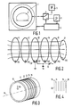
- the magnetic resonance tomograph shown in FIG. 1 contains a high-frequency coil arrangement 1 with a hollow cylindrical cross-section, which inside generates a high-frequency magnetic field that is perpendicular to the plane of the drawing and penetrates the examination area in which the examination object 2 is located, for example a patient whose longitudinal axis is perpendicular to the plane of the drawing runs.
- the magnetic resonance tomograph has a main field magnet, not shown, which generates a stationary, homogeneous magnetic field running in the vertical direction with a magnetic flux density of a few tenths of a T or less.
- the stationary magnetic field and the high-frequency field are therefore perpendicular to each other.
- there are also gradient coils - likewise not shown in detail - which also produce magnetic fields that run in the vertical direction, but with a gradient in one of three directions perpendicular to each other.
- a control unit 3 controls the generation of the fields described above and processes the nuclear magnetic resonance signals received from the examination area.
- it acts on an electronic switch 4, by means of which the radio-frequency coil arrangement 1 is switched from transmission mode - in which it is connected to an oscillator 5 - to reception mode, in which it is connected to a radio-frequency receiver 6, which amplifies, demodulates and demodulates the nuclear magnetic resonance signals converted into a sequence of digital data words that are processed in unit 3.
- the high-frequency coil arrangement 1 consists of a number of resonators 11 ... 15.
- the resonators are arranged on a cylindrical carrier body 10, the central axis 16 of which runs perpendicular to the homogeneous stationary magnetic field B0.
- Each resonator comprises a conductor loop which surrounds the carrier body in a ring and is only interrupted at a point which is capacitively bridged.
- the conductor loops are located in parallel planes which are preferably perpendicular to the longitudinal axis 16 of the carrier body 10.
- the capacitance of the open ends of the conductor loops 11 .. 15 bridging capacitors 110 ... 150 is chosen so that all resonators (by themselves) are tuned to the same resonance frequency.
- this tuning takes place by means of two capacitors 131 and 132 of equal size, connected in series, the connection point of which is grounded.
- the connection of one of the two capacitors (132) facing away from this connection point is connected to the changeover switch 4 (FIG. 1) via a matching and tuning network 8.
- the conductor loops can also be interrupted at a plurality of points which are evenly offset relative to one another on the circumference and can be bridged by a capacitor with a suitable capacitance. Although this increases the outlay, the dielectric losses occurring during operation are further reduced or the quality is further increased.
- the resonators formed by a conductor loop and one or two capacitors are not galvanically connected to one another. However, they are inductively coupled to one another because the conductor loops are located in parallel planes. Because of the missing Galvanic connection between the individual conductor loops, the propagation effects are determined only by the dimensions of the conductor loop 13 that can be coupled to the high-frequency transmitter 5 or the high-frequency receiver 6. With a diameter of the tube 10 of 600 mm, the length of such a conductor loop (almost 2 m) is still small compared to a quarter of the wavelength (35 m), which is at a magnetic flux density of the stationary homogeneous magnetic field B0 of 0.2 T and the associated magnetic resonance frequency of around 8.5 MHz.
- the inductive coupling between the different resonators results in a concentration of the generated magnetic field, which runs in the direction of the central axis 16 or perpendicular to the plane of the resonators, as indicated in FIG. 2, essentially in the space enclosed by the resonators - Similar to a solenoid coil with a corresponding number of turns.
- the quality and in particular the coil sensitivity are therefore the better the more resonators are present. In practice, therefore, more than just the five resonators shown in the figures will be used.
- the number of resonance frequencies corresponds to the number of resonators; the resonance frequency is the frequency at which the ratio of the energy in the resonator to the energy supplied to the resonator has a maximum.
- Each resonance frequency is linked to a different vibration mode. The lowest resonance frequency results when a current flows in the same direction in all resonators. This resonance frequency is lower than the frequency to which the individual resonators are tuned.
- the highest resonance frequency is obtained when the direction of current flow is reversed from resonator to resonator; this frequency is much higher than the frequency to which the resonators are tuned.
- the advantage of this mode of vibration is that it cannot be excited by a homogeneous external magnetic field. If one operates such a coil arrangement as a receiving coil in the field of an (additional) transmitting coil, there is a large decoupling between the coils, especially if the receiving coil consists of an even number of resonators.
- the advantage here is that conventional transmitter coils mostly also lie on a cylinder jacket, but generate a field perpendicular to the cylinder axis. The receiving coil can therefore be arranged concentrically to the transmitting coil in its interior.
- a high-frequency coil for nuclear spin examinations in the head area seven resonators were applied to a carrier body with a diameter of 320 mm. Each resonator consisted of 12 mm thick copper tube, which was tuned to a frequency of approximately 11 MHz using a 320 pF capacitor. The distance between the conductor loops was 20 mm. This arrangement was operated at the lowest resonance frequency, which was 6.8 MHz. This resulted in an idling quality of 120 and a loaded quality of about 280. Saddle coils have similarly high idling and operating speeds at such resonator frequencies quality so that they are not inferior in broadcast mode.
- the sensitivity of a saddle coil is around 40% lower, so that the high-frequency coil arrangement according to the invention has significant advantages in reception mode.
- the quality of a high-frequency coil arrangement according to the invention decreases far less than that of a saddle coil, so that there are advantages with regard to the transmission mode even at lower frequencies.
- a high frequency coil with a circular cross section has been described above.
- the high-frequency coil can also have a different cross section, for example an elliptical or a square one.
- the center points or the centroids of the surfaces enclosed by the individual conductor loops should lie on a common straight line, and the mutually parallel planes in which the conductor loops are located should intersect this straight line as perpendicularly as possible.
- a further conductor loop 17 can be provided, which is arranged concentrically to the central axis 16 and which has a smaller diameter than this.
- This conductor loop must be tuned to the same frequency as the other resonators, but this requires a capacitor 170 with a larger capacitance because of the reduced inductance of this loop.
- the effect of this smaller resonator 17, which is located at one end of the high-frequency coil arrangement, is expressed in that the magnetic flux density drops even more in the axial direction towards the outside, so that the magnetic field is concentrated even more in the space enclosed by the coils .
- a conductive screen 18 made of a 30 ⁇ m thick copper foil is arranged on the side of the coil facing away from the patient entry side. This increases the field in the center of the coil, thus additionally causing a field concentration and thus a better signal-to-noise ratio.
- a further screen 19 can be arranged, which is provided with an opening - indicated by dashed lines in FIG. 4 with 20 - for the patient's head . This shields the shoulder area of the patient and stray fields, which create an additional patient burden.
Abstract
Die Erfindung betrifft ein Kernspinresonanzgerät mit einer Hochfrequenzspule. Dabei wird eine hohe Güte und Empfindlichkeit dadurch erreicht, daß die Spule aus einzelnen auf die gleiche Resonanzfrequenz abgestimmten Resonatoren (11-15, 17) besteht, die lediglich induktiv miteinander gekoppelt aber nicht galvanisch miteinander verbunden sind.The invention relates to a nuclear magnetic resonance device with a high-frequency coil. A high quality and sensitivity is achieved in that the coil consists of individual resonators (11-15, 17) tuned to the same resonance frequency, which are only inductively coupled to one another but not galvanically connected to one another.
Description
Die Erfindung betrifft ein Kernspinuntersuchungsgerät mit einer Hochfrequenzspulenanordnung, die an einen Hochfrequenzsender und/oder an einen Hochfrequenzempfänger anschließbar ist.The invention relates to an MRI device with a high-frequency coil arrangement that can be connected to a high-frequency transmitter and / or to a high-frequency receiver.
Es ist bekannt, daß das Signal-Rausch-Verhältnis beim Empfang von Kernspinresonanzsignalen umso ungünstiger wird, je niedriger die Magnetflußdichte des stationären homogenen Magnetfeldes ist, dem der Untersuchungsbereich bei einer Kernspinuntersuchung ausgesetzt ist. Um auch bei Kernspinresonanzgeräten mit niedriger Magnetflußdichte noch ein akzeptables Signalrauschverhältnis zu erreichen, ist es wichtig, daß die Hochfrequenzspulenanordnung, die die Kernspinresonanzsignale aufnimmt, eine hohe Güte und eine hohe Empfindlichkeit aufweist. Es ist bekannt, daß eine sogenannte Solenoid-Spule mit einer genügenden Anzahl von Windungen diese Eigenschaften aufweist. Jedoch kann die Windungszahl nur so groß gewählt werden, daß die Länge des Leiters, aus dem diese Spule gewickelt ist, kleiner ist als eine Viertel Wellenlänge der Betriebsfrequenz, vorzugsweise klein im Vergleich dazu.It is known that the signal-to-noise ratio when receiving nuclear magnetic resonance signals becomes less favorable the lower the magnetic flux density of the stationary homogeneous magnetic field to which the examination area is exposed during an MRI examination. In order to achieve an acceptable signal-to-noise ratio even with nuclear magnetic resonance devices with a low magnetic flux density, it is important that the high-frequency coil arrangement which receives the magnetic resonance signals has a high quality and a high sensitivity. It is known that a so-called solenoid coil with a sufficient number of turns has these properties. However, the number of turns can only be chosen so large that the length of the conductor from which this coil is wound is less than a quarter wavelength of the operating frequency, preferably small in comparison.
Murton und Neale haben daher eine Spulenanordnung beschrieben, bei der zwei Spulen mit je drei Windungen parallel geschaltet sind. Auch hier liegt die Eigenresonanzfrequenz aufgrund unvermeidbarer Spulenkapazitäten noch relativ niedrig, so daß sich Wellenausbreitungseffekte bemerkbar machen können, die zu einer Zunahme der dielektrischen Verluste und damit zu einer Abnahme der Güte führen.Murton and Neale have therefore described a coil arrangement in which two coils, each with three turns, are connected in parallel. Here, too, the natural resonance frequency is still relatively low due to unavoidable coil capacitances, so that wave propagation effects can be noticed, which lead to an increase in the dielectric losses and thus to a decrease in the quality.
Aufgabe der vorliegenden Erfindung ist es, eine Hochfrequenzspulenanordnung für ein Kernspinresonanzgerät zu schaffen, die auch bei vergleichsweise niedriger Kernspinresonanzfrequenz einen günstigen Signal-Rausch-Abstand und eine hohe Güte aufweist. Diese Aufgabe wird erfindungsgemäß dadurch gelöst, daß die Hochfrequenzspulenanordnung mehrere auf die gleiche Frequenz abgestimmte Resonatoren umfaßt, daß jeder Resonator eine ein- oder mehrteilige Leiterschleife umfaßt, deren Enden kapazitiv miteinander gekoppelt sind, daß die galvanisch miteinander nicht verbundenen Resonatoren induktiv miteinander gekoppelt sind und daß im Betriebszustand einer der Resonatoren an den Hochfrequenzsender bzw. an den Hochfrequenzempfänger angeschlossen ist.The object of the present invention is to provide a high-frequency coil arrangement for a nuclear magnetic resonance device, which has a favorable signal-to-noise ratio and a high quality even at a comparatively low nuclear magnetic resonance frequency. This object is achieved in that the high-frequency coil arrangement comprises a plurality of resonators tuned to the same frequency, that each resonator comprises a one-part or multi-part conductor loop, the ends of which are capacitively coupled to one another, that the resonators which are not electrically connected are inductively coupled to one another and that in the operating state, one of the resonators is connected to the high-frequency transmitter or to the high-frequency receiver.
Die Erfindung verwendet also eine Anzahl von Resonatoren, die jeweils durch eine Leiterschleife gebildet werden, die in der Regel mittels eines zusätzlichen Kondensators auf die gleiche Frequenz abgestimmt sind. Die einzelnen Resonatoren sind galvanisch nicht miteinander verbunden, sondern induktiv miteinander gekoppelt. Nur einer der Resonatoren ist im Betrieb an den Hochfrequenzsender bzw. an den Hochfrequenzempfänger angeschlossen. Eine derartige Hochfrequenzspulenanordnung verhält sich daher hinsichtlich der Wellenausbreitungseffekte und der damit verbundenen dielektrischen Verluste wie eine Hochfrequenzspule mit nur einer Windung, hinsichtlich der Empfindlichkeit jedoch wie eine Solenoid-Spule, deren Windungszahl der Zahl der Resonatoren entspricht.The invention thus uses a number of resonators, each of which is formed by a conductor loop, which are generally tuned to the same frequency by means of an additional capacitor. The individual resonators are not galvanically connected to one another, but rather inductively coupled to one another. Only one of the resonators is connected to the high-frequency transmitter or to the high-frequency receiver during operation. Such a high-frequency coil arrangement therefore behaves like a high-frequency coil with only one turn with regard to the wave propagation effects and the associated dielectric losses, but with regard to sensitivity like a solenoid coil whose number of turns corresponds to the number of resonators.
Bei einer erfindungsgemäßen Hochfrequenzspulenanordnung gibt es so viele Schwingungsmoden wie es Resonatoren gibt. Bei einem Schwingungsmodus fließen die Ströme in sämtlichen Resonatoren mit dem gleichen Umlaufsinn. Dieser Schwindungsmodus ist mit der niedrigsten Resonanzfrequenz verknüpft, die unterhalb der Frequenz liegt, auf die die einzelnen Resonatoren abgestimmt sind. Bei einem anderen Schwingungsmodus haben die Ströme in räumlich benachbarten Resonatoren immer den entgegengesetzten Umlaufsinn. Bei diesem Schwingungsmodus ergibt sich die höchste Resonanzfrequenz, die oberhalb der Frequenz liegt, auf die die Resonatoren abgestimmt sind. Dieser Schwingungsmodus kann nur dadurch angeregt werden, daß einem der Resonatoren ein Strom mit der betreffenden Frequenz zugeführt wird; durch ein äußeres homogenes Hochfrequenzfeld kann er hingegen nicht hervorgerufen werden. Bei Verwendung einer erfindungsgemäßen Hochfrequenzspulenanordnung zum Empfang von Kernspinresonanzsignalen kann diese daher vollständig von einer Sendespule entkoppelt werden, die auf der gleichen Resonanzfrequenz arbeitet.In a high-frequency coil arrangement according to the invention, there are as many vibration modes as there are resonators. In an oscillation mode, the currents flow in the same direction in all resonators. This mode of shrinkage has the lowest resonance frequency linked, which is below the frequency to which the individual resonators are tuned. In another mode of oscillation, the currents in spatially adjacent resonators always have the opposite sense of rotation. This oscillation mode results in the highest resonance frequency, which is above the frequency to which the resonators are tuned. This mode of oscillation can only be excited by supplying a current with the relevant frequency to one of the resonators; however, it cannot be caused by an external homogeneous high-frequency field. When using a high-frequency coil arrangement according to the invention for receiving nuclear magnetic resonance signals, it can therefore be completely decoupled from a transmitting coil which operates at the same resonance frequency.
In Ausgestaltung der Erfindung ist vorgesehen, daß im Betriebszustand ein senkrecht verlaufendes homogenes stationäres Magnetfeld auf den von der Hochfrequenzspulenanordnung umschlossenen Untersuchungsbereich einwirkt. In einem Kernspintomographen wird ein Patient in der Regel liegend untersucht. Die Hochfrequenzspulenanordnung hat dann also eine horizontal verlaufende Längsachse und erzeugt ein in diese Richtung verlaufendes hochfrequentes Magnetfeld, zu dem das vertikale, homogene und stationäre Magnetfeld senkrecht steht - wie es erforderlich ist.In an embodiment of the invention it is provided that, in the operating state, a vertically running, homogeneous, stationary magnetic field acts on the examination area enclosed by the high-frequency coil arrangement. A patient is usually examined lying down in an MRI scanner. The high-frequency coil arrangement then has a horizontally running longitudinal axis and generates a high-frequency magnetic field running in this direction, to which the vertical, homogeneous and stationary magnetic field is perpendicular - as is necessary.
Die Erfindung wird nachstehend anhand der Zeichnung näher erläutert. Es zeigen:
- Fig. 1 einen Kernspintomographen, bei dem die Erfindung anwendbar ist.
- Fig. 2 ein elektrisches Prinzipschaltbild und
- Fig. 3 die räumliche Gestaltung einer erfindungsgemäßen Hochfrequenzspule.
- Fig. 4 eine Modifikation dieser Spule.
- Fig. 1 shows a magnetic resonance scanner, in which the invention is applicable.
- Fig. 2 is an electrical schematic and
- Fig. 3 shows the spatial design of a high-frequency coil according to the invention.
- Fig. 4 shows a modification of this coil.
Der in Fig. 1 dargestellte Kernspintomograph enthält eine Hochfrequenzspulenanordnung 1 mit hohlzylindrischem Querschnitt, die in ihrem Innern ein zur Zeichenebene senkrechtes, hochfrequentes Magnetfeld erzeugt, das den Untersuchungsbereich durchsetzt, in dem sich das Untersuchungsobjekt 2 befindet, beispielsweise ein Patient, dessen Längsachse senkrecht zur Zeichenebene verläuft. Der Kernspintomograph besitzt einen nicht näher dargestellten Hauptfeldmagneten, der ein in vertikaler Richtung verlaufendes stationäres homogenes Magnetfeld mit einer Magnetflußdichte von einigen Zehntel T oder weniger erzeugt. Das stationäre Magnetfeld und das Hochfrequenzfeld stehen also senkrecht zueinander. Daneben gibt es noch Gradientenspulen - ebenfalls nicht näher dargestellt - die ebenfalls in vertikaler Richtung verlaufende Magnetfelder erzeugen, jedoch mit einem Gradienten in jeweils einer von drei zueinander senkrecht stehenden Richtungen.The magnetic resonance tomograph shown in FIG. 1 contains a high-frequency coil arrangement 1 with a hollow cylindrical cross-section, which inside generates a high-frequency magnetic field that is perpendicular to the plane of the drawing and penetrates the examination area in which the examination object 2 is located, for example a patient whose longitudinal axis is perpendicular to the plane of the drawing runs. The magnetic resonance tomograph has a main field magnet, not shown, which generates a stationary, homogeneous magnetic field running in the vertical direction with a magnetic flux density of a few tenths of a T or less. The stationary magnetic field and the high-frequency field are therefore perpendicular to each other. In addition, there are also gradient coils - likewise not shown in detail - which also produce magnetic fields that run in the vertical direction, but with a gradient in one of three directions perpendicular to each other.
Eine Steuereinheit 3 steuert die Erzeugung der zuvor beschriebenen Felder und verarbeitet die aus dem Untersuchungsbereich empfangenen Kernspinresonanzsignale. Insbesondere wirkt sie auf einen elektronischen Umschalter 4 ein, mittels dessen die Hochfrequenzspulenanordnung 1 von Sendebetrieb - in dem sie mit einem Oszillator 5 verbunden ist - auf Empfangsbetrieb umgeschaltet wird, in dem sie mit einem Hochfrequenzempfänger 6 verbunden ist, der die Kernresonanzsignale verstärkt, demoduliert und in eine Folge digitaler Datenworte umsetzt, die in der Einheit 3 verarbeitet werden.A control unit 3 controls the generation of the fields described above and processes the nuclear magnetic resonance signals received from the examination area. In particular, it acts on an electronic switch 4, by means of which the radio-frequency coil arrangement 1 is switched from transmission mode - in which it is connected to an oscillator 5 - to reception mode, in which it is connected to a radio-
Wie sich aus den Fig. 2 und 3 ergibt, besteht die Hochfrequenzspulenanordnung 1 aus einer Anzahl von Resonatoren 11 ... 15. Die Resonatoren sind auf einem zylinderförmigen Trägerkörper 10 angeordnet, dessen Mittelachse 16 senkrecht zu dem homogenen stationären Magnetfeld B₀ verläuft. Jeder Resonator umfaßt eine Leiterschleife, die den Trägerkörper ringförmig umschließt und nur an einer Stelle unterbrochen wird, die kapazitiv überbrückt ist. Die Leiterschleifen befinden sich in parallelen, zur Längsachse 16 des Trägerkörpers 10 vorzugsweise senkrechten Ebenen. Die Kapazität der offenen Enden der Leiterschleifen 11 .. 15 überbrückenden Kondensatoren 110 ... 150 ist so gewählt, daß alle Resonatoren (für sich allein) auf dieselbe Resonanzfrequenz abgestimmt sind. Bei der mittleren Leiterschleife 13 erfolgt diese Abstimmung mittels zweier gleich großer, in Serie geschalteter Kondensatoren 131 und 132, deren Verbindungspunkt geerdet ist. Der von diesem Verbindungspunkt abgewandte Anschluß eines der beiden Kondensatoren (132) ist über ein Anpaß- und Abstimmnetzwerk 8 mit dem Umschalter 4 (Fig. 1) verbunden.2 and 3, the high-frequency coil arrangement 1 consists of a number of
Anstatt an jeweils einer Stelle können die Leiterschleifen auch an mehreren auf dem Umfang jeweils gleichmäßig gegeneinander versetzten Stellen unterbrochen und durch einen Kondensator mit geeigneter Kapazität überbrückt sein. Dadurch vergrößert sich zwar der Aufwand, doch werden dadurch die im Betrieb auftretenden dielektrischen Verluste noch weiter reduziert bzw. die Güte noch weiter vergrößert.Instead of at one point in each case, the conductor loops can also be interrupted at a plurality of points which are evenly offset relative to one another on the circumference and can be bridged by a capacitor with a suitable capacitance. Although this increases the outlay, the dielectric losses occurring during operation are further reduced or the quality is further increased.
Die durch eine Leiterschleife und einen bzw. zwei Kondensatoren gebildeten Resonatoren sind nicht galvanisch miteinander verbunden. Sie sind jedoch induktiv miteinander gekoppelt, weil die Leiterschleifen sich in parallelen Ebenen befinden. Wegen der fehlenden galvanischen Verbindung zwischen den einzelnen Leiterschleifen werden die Ausbreitungseffekte lediglich durch die Abmessungen der mit dem Hochfrequenzsender 5 bzw. dem Hochfrequenzempfänger 6 koppelbaren Leiterschleife 13 bestimmt. Bei einem Durchmesser des Rohres 10 von 600 mm ist die Länge einer solchen Leiterschleife (knapp 2 m) aber immer noch klein im Vergleich zu einem Viertel der Wellenlänge (35 m), die sich bei einer Magnetflußdichte des stationären homogenen Magnetfeldes B₀ von 0,2 T und der damit verbundenen Kernspinresonanzfrequenz von rund 8,5 MHz ergibt. Auf der anderen Seite resultiert aus der induktiven Kopplung zwischen den verschiedenen Resonatoren eine Konzentration des erzeugten Magnetfeldes, das in Richtung der Mittelachse 16 bzw. senkrecht zur Ebene der Resonatoren verläuft, wie in Fig. 2 angedeutet, im wesentlichen in dem von den Resonatoren umschlossenen Raum - ähnlich wie bei einer Solenoid-Spule mit einer entsprechenden Anzahl von Windungen. Die Güte und insbesondere die Spulenempfindlichkeit sind daher umso besser, je mehr Resonatoren vorhanden sind. In der Praxis wird man daher auch mehr als nur die in den Figuren dargestellten fünf Resonatoren verwenden.The resonators formed by a conductor loop and one or two capacitors are not galvanically connected to one another. However, they are inductively coupled to one another because the conductor loops are located in parallel planes. Because of the missing Galvanic connection between the individual conductor loops, the propagation effects are determined only by the dimensions of the
Neben der starken Feldkonzentration, insbesondere im Zentrum (im Bereich des Resonators 13), besteht ein weiterer Vorteil in der ausgezeichneten Homogenität des Hochfrequenzfeldes im Innern der Spule.In addition to the strong field concentration, particularly in the center (in the region of the resonator 13), there is a further advantage in the excellent homogeneity of the high-frequency field in the interior of the coil.
Bei einer aus mehreren Resonatoren bestehenden Hochfrequenzspulenanordnung entspricht die Zahl der Resonanzfrequenzen der Zahl der Resonatoren; als Resonanzfrequenz ist dabei diejenige Frequenz bezeichnet, bei der das Verhältnis der Energie im Resonator zu der dem Resonator zugeführten Energie ein Maximum hat. Die Resonanzfrequenzen liegen umso weiter auseinander, je stärker die induktive Kopplung zwischen den einzelnen Resonatoren ist, d.h. je dichter die Leiterschleifen beieinander liegen. Jede Resonanzfrequenz ist mit einem anderen Schwingungsmodus verknüpft. Die niedrigste Resonanzfrequenz ergibt sich, wenn in allen Resonatoren ein Strom mit gleichem Umlaufsinn fließt. Diese Resonanzfrequenz ist niedriger als die Frequenz, auf die die einzelnen Resonatoren abgestimmt sind. Die höchste Resonanzfrequenz ergibt sich, wenn der Umlaufsinn des Stromes von Resonator zu Resonator umgekehrt ist; diese Frequenz ist wesentlich höher als die Frequenz, auf die die Resonatoren abgestimmt sind. Der Vorteil dieses Schwingungsmodus ist, daß er durch ein homogenes äußeres Magnetfeld nicht angeregt werden kann. Wenn man eine solche Spulenanordnung als Empfangsspule im Feld einer (zusätzlichen) Sendespule betreibt, ergibt sich eine weitgehende Entkopplung zwischen den Spulen, insbesondere, wenn die Empfangsspule aus einer geraden Anzahl von Resonatoren besteht. Dabei ist von Vorteil, daß herkömmliche Sendespulen meist ebenfalls auf einem Zylindermantel liegen, aber ein zur Zylinderachse senkrechtes Feld erzeugen. Die Empfangsspule kann also konzentrisch zur Sendespule in deren Inneren angeordnet sein.In the case of a high-frequency coil arrangement consisting of several resonators, the number of resonance frequencies corresponds to the number of resonators; the resonance frequency is the frequency at which the ratio of the energy in the resonator to the energy supplied to the resonator has a maximum. The stronger the inductive frequencies, the further apart the resonance frequencies There is coupling between the individual resonators, ie the closer the conductor loops are to one another. Each resonance frequency is linked to a different vibration mode. The lowest resonance frequency results when a current flows in the same direction in all resonators. This resonance frequency is lower than the frequency to which the individual resonators are tuned. The highest resonance frequency is obtained when the direction of current flow is reversed from resonator to resonator; this frequency is much higher than the frequency to which the resonators are tuned. The advantage of this mode of vibration is that it cannot be excited by a homogeneous external magnetic field. If one operates such a coil arrangement as a receiving coil in the field of an (additional) transmitting coil, there is a large decoupling between the coils, especially if the receiving coil consists of an even number of resonators. The advantage here is that conventional transmitter coils mostly also lie on a cylinder jacket, but generate a field perpendicular to the cylinder axis. The receiving coil can therefore be arranged concentrically to the transmitting coil in its interior.
Bei einem in der Praxis untersuchten Ausführungsbeispiel einer Hochfrequenzspule für Kernspinuntersuchungen im Kopfbereich wurden auf einen Trägerkörper mit einem Durchmesser von 320 mm sieben Resonatoren aufgebracht. Jeder Resonator bestand aus 12 mm starkem Kupferrohr, das mittels eines Kondensators von 320 pF auf eine Frequenz von etwa 11 MHz abgestimmt war. Der Abstand der Leiterschleifen betrug 20 mm. Diese Anordnung wurde bei der niedrigsten Resonanzfrequenz betrieben, die bei 6,8 MHz lag. Hier ergab sich eine Leerlaufgüte von 120 und eine belastete Güte von etwa 280. Sattelspulen weisen bei solchen Resonatorfrequenzen zwar ähnlich hohe Leerlauf- und Betriebs güten auf, so daß sie im Sendebetrieb nicht unterlegen sind. Jedoch ist die Empfindlichkeit einer Sattelspule um rund 40 % niedriger,so daß die erfindungsgemäße Hochfrequenzspulenanordnung im Empfangsbetrieb wesentliche Vorteile aufweist. Zu niedrigen Frequenzen hin nimmt die Güte einer Hochfrequenzspulenanordnung nach der Erfindung weitaus weniger ab als die einer Sattelspule, so daß sich bei noch niedrigern Frequenzen also auch hinsichtlich des Sendebetriebes Vorteile ergeben.In one exemplary embodiment of a high-frequency coil for nuclear spin examinations in the head area, seven resonators were applied to a carrier body with a diameter of 320 mm. Each resonator consisted of 12 mm thick copper tube, which was tuned to a frequency of approximately 11 MHz using a 320 pF capacitor. The distance between the conductor loops was 20 mm. This arrangement was operated at the lowest resonance frequency, which was 6.8 MHz. This resulted in an idling quality of 120 and a loaded quality of about 280. Saddle coils have similarly high idling and operating speeds at such resonator frequencies quality so that they are not inferior in broadcast mode. However, the sensitivity of a saddle coil is around 40% lower, so that the high-frequency coil arrangement according to the invention has significant advantages in reception mode. Towards low frequencies, the quality of a high-frequency coil arrangement according to the invention decreases far less than that of a saddle coil, so that there are advantages with regard to the transmission mode even at lower frequencies.
Vorstehend wurde eine Hochfrequenzspule mit kreisförmigem Querschnitt beschrieben. Die Hochfrequenzspule kann aber auch einen anderen Querschnitt haben, beispielsweise einen elliptischen oder einen quadratischen. Die Mittelpunkte bzw. die Flächenschwerpunkte der von den einzelnen Leiterschleifen umschlossenen Flächen sollten dabei auf einer gemeinsamen Geraden liegen, und die zueinander parallelen Ebenen, in denen sich die Leiterschleifen befinden, sollten diese Gerade möglichst senkrecht schneiden.A high frequency coil with a circular cross section has been described above. However, the high-frequency coil can also have a different cross section, for example an elliptical or a square one. The center points or the centroids of the surfaces enclosed by the individual conductor loops should lie on a common straight line, and the mutually parallel planes in which the conductor loops are located should intersect this straight line as perpendicularly as possible.
Es ist nicht erforderlich, daß alle Leiterschleifen die gleiche Größe haben. Wie in Fig. 2 gestrichelt angedeutet, kann eine weitere Leiterschleife 17 vorgesehen sein, die konzentrisch zur Mittelachse 16 angeordnet ist und die einen geringeren Durchmesser aufweist als diese. Diese Leiterschleife muß auf die gleiche Frequenz abgestimmt sein wie die anderen Resonatoren, wozu aber wegen der verringerten Induktivität dieser Schleife ein Kondensator 170 mit größerer Kapazität erforderlich ist. Die Wirkung dieses kleineren Resonators 17, der sich an dem einen Ende der Hochfrequenzspulenanordnung befindet, äußert sich darin, daß die Magnetflußdichte in axialer Richtung nach außen hin noch stärker abfällt, so daß das magnetische Feld noch stärker in dem von den Spulen umschlossenen Raum konzentriert wird. Wenn dann der Gene rator bzw. der Empfänger nicht an den mittleren Resonator 13 sondern an den der Spule 17 benachbarten Resonator 15 angeschlossen wird, ergibt sich auch zur anderen Seite der Spule hin eine stärkere Abnahme des Magnetfeldes. Bei der Benutzung einer derartigen Hochfrequenzspule als Kopfspule ergeben sich insofern Vorteile, als dem dann links vom Resonator 11 befindlichen Hals- und Schulterbereich weniger Hochfrequenzenergie zugeführt wird und dieser Bereich die Spulengüte daher weniger belastet.It is not necessary that all conductor loops are the same size. As indicated by dashed lines in FIG. 2, a further conductor loop 17 can be provided, which is arranged concentrically to the
In Fig. 4 ist an der von der Patienteneintrittsseite abgewandten Seite der Spule ein zur Spulenachse senkrechter leitfähiger Schirm 18 aus einer 30µm dicken Kupferfolie angeordnet. Dieser erhöht das Feld im Zentrum der Spule, bewirkt also zusätzlich eine Feldkonzentration und damit ein besseres Signal-Rausch-Verhältnis.In FIG. 4, a
Zusätzlich kann - bei Verwendung als Kopfspule - auf der Seite der Spule, auf der der Patient mit seinem Kopf eingeführt wird, ein weiterer Schirm 19 angeordnet werden, der mit einer Öffnung - in Fig. 4 mit 20 gestrichelt angedeutet - für den Patientenkopf versehen ist. Dieser schirmt den Schulterbereich des Patienten und Streufelder ab, welche eine zusätzliche Patientenbelastung erzeugen.In addition - when used as a head coil - on the side of the coil on which the patient is introduced with his head, a further screen 19 can be arranged, which is provided with an opening - indicated by dashed lines in FIG. 4 with 20 - for the patient's head . This shields the shoulder area of the patient and stray fields, which create an additional patient burden.
Claims (11)
dadurch gekennzeichnet, daß die Hochfrequenzspulenanordnung (1) mehrere auf die gleiche Frequenz abgestimmte Resonatoren umfaßt, daß jeder Resonator eine ein- oder mehrteilige Leiterschleife (11...15)umfaßt, deren Enden kapazitiv miteinander gekoppelt sind, daß die galvanisch miteinander nicht verbundenen Resonatoren induktiv miteinander gekoppelt sind und daß im Betriebszustand einer der Resonatoren an den Hochfrequenzsender bzw. an den Hochfrequenzempfänger angeschlossen ist.1. magnetic resonance examination device with a high-frequency coil arrangement which can be connected to a high-frequency transmitter and / or to a high-frequency receiver,
characterized in that the high-frequency coil arrangement (1) comprises a plurality of resonators tuned to the same frequency, in that each resonator comprises a single-part or multi-part conductor loop (11 ... 15), the ends of which are capacitively coupled to one another, that the resonators which are not electrically connected to one another are inductively coupled to each other and that in the operating state one of the resonators is connected to the high-frequency transmitter or to the high-frequency receiver.
dadurch gekennzeichnet, daß die Leiterschleifen der Resonatoren in parallelen Ebenen liegen und ihre Mittelpunkte auf einer gemeinsamen Geraden angeordnet sind.2. MRI scanner according to claim 1,
characterized in that the conductor loops of the resonators lie in parallel planes and their centers are arranged on a common straight line.
dadurch gekennzeichnet, daß die Resonatoren auf der Oberfläche eines Zylinders angeordnet sind.3. MRI scanner according to one of the preceding claims,
characterized in that the resonators are arranged on the surface of a cylinder.
dadurch gekennzeichnet, daß der letzte Resonator die gleiche Form aber eine geringere Größe hat wie die übrigen Resonatoren.4. MRI scanner according to one of the preceding claims,
characterized in that the last resonator has the same shape but a smaller size than the other resonators.
dadurch gekennzeichnet, daß die Sende- bzw. die Empfangsfrequenz der am niedrigsten liegenden Resonanzfrequenz der Hochfrequenzspulenanordnung entspricht.5. MRI scanner according to one of the preceding claims,
characterized in that the transmission or reception frequency corresponds to the lowest lying resonance frequency of the high-frequency coil arrangement.
dadurch gekennzeichnet, daß die Sende- bzw. die Empfangsfrequenz der am höchsten liegenden Resonanzfrequenz der Hochfrequenzspulenanordnung entspricht.6. MRI scanner according to one of claims 1 to 4,
characterized in that the transmission or reception frequency corresponds to the highest lying resonance frequency of the high-frequency coil arrangement.
dadurch gekennzeichnet, daß die Hochfrequenzspulenanordnung durch eine gerade Zahl von Resonatoren gebildet wird.7. MRI scanner according to claim 6,
characterized in that the high-frequency coil arrangement is formed by an even number of resonators.
dadurch gekennzeichnet, daß im Betriebszustand ein senkrecht verlaufendes homogenes stationäres Magnetfeld (B₀) auf den von der Hochfrequenzspulenanordnung (1) umschlossenen Untersuchungsbereich einwirkt.8. MRI device according to one of the preceding claims,
characterized in that in the operating state a vertically running, homogeneous, stationary magnetic field (B₀) acts on the examination area enclosed by the high-frequency coil arrangement (1).
dadurch gekennzeichent, daß die Hochfrequenzspulenanordnung (11...15) zum Signalempfang dient und im Innern einer dazu konzentrischen Sendespule angeordnet ist, deren Hochfrequenzfeld senkrecht zur Spulenachse verläuft.9. MRI device according to one of the preceding claims,
characterized in that the high-frequency coil arrangement (11 ... 15) serves for signal reception and is arranged in the interior of a concentric transmission coil, the high-frequency field of which runs perpendicular to the coil axis.
dadurch gekennzeichnet, daß der Schirm auf der Patienteneintrittsseite eine Öffnung (20) aufweist.11. MRI scanner according to claim 10,
characterized in that the screen has an opening (20) on the patient entry side.
Applications Claiming Priority (2)
| Application Number | Priority Date | Filing Date | Title |
|---|---|---|---|
| DE3816831 | 1988-05-18 | ||
| DE3816831A DE3816831A1 (en) | 1988-05-18 | 1988-05-18 | CORE SPIN EXAMINATION DEVICE WITH A HIGH-FREQUENCY COIL ARRANGEMENT |
Publications (3)
| Publication Number | Publication Date |
|---|---|
| EP0342745A2 true EP0342745A2 (en) | 1989-11-23 |
| EP0342745A3 EP0342745A3 (en) | 1991-01-16 |
| EP0342745B1 EP0342745B1 (en) | 1995-12-20 |
Family
ID=6354574
Family Applications (1)
| Application Number | Title | Priority Date | Filing Date |
|---|---|---|---|
| EP89201194A Expired - Lifetime EP0342745B1 (en) | 1988-05-18 | 1989-05-12 | Nuclear spin examining apparatus with a radio frequency coil arrangement |
Country Status (4)
| Country | Link |
|---|---|
| US (1) | US5003265A (en) |
| EP (1) | EP0342745B1 (en) |
| JP (1) | JP2801262B2 (en) |
| DE (2) | DE3816831A1 (en) |
Cited By (7)
| Publication number | Priority date | Publication date | Assignee | Title |
|---|---|---|---|---|
| EP0401917A2 (en) * | 1989-06-08 | 1990-12-12 | Philips Patentverwaltung GmbH | High-frequency quadrature coil system |
| FR2655157A1 (en) * | 1989-11-24 | 1991-05-31 | Mehier Henri | Method for improving the Q factor of antennas, and more particularly of the surface coils used in medical applications of nuclear magnetic resonance, and a device for its implementation |
| EP0486086A1 (en) * | 1990-11-10 | 1992-05-20 | Philips Patentverwaltung GmbH | Quadrature coils system |
| DE4104079A1 (en) * | 1991-02-11 | 1992-08-13 | Bruker Medizintech | SAMPLE HEAD FOR NMR TOMOGRAPHY |
| EP0541696A1 (en) * | 1990-08-02 | 1993-05-19 | Fox Chase Cancer Center | A multiple radio frequency volume resonator for nuclear magnetic resonance |
| EP0583824A2 (en) * | 1992-08-13 | 1994-02-23 | Philips Patentverwaltung GmbH | Coil arrangement for magnetic resonance female breast examination |
| EP0803737A2 (en) * | 1996-04-26 | 1997-10-29 | Picker International, Inc. | Radio frequency coils |
Families Citing this family (27)
| Publication number | Priority date | Publication date | Assignee | Title |
|---|---|---|---|---|
| US5583438A (en) * | 1989-04-12 | 1996-12-10 | Fonar Corporation | Inductively coupled dedicated RF coils for MRI |
| US5315251A (en) * | 1990-12-19 | 1994-05-24 | Toshiba America Mri, Inc. | NMR radio-frequency coil |
| US5585721A (en) * | 1991-06-24 | 1996-12-17 | Fonar Corporation | Inductively coupled dedicated RF coils for MRI |
| US5585723A (en) * | 1995-03-23 | 1996-12-17 | Conductus, Inc. | Inductively coupled superconducting coil assembly |
| US5365173A (en) * | 1992-07-24 | 1994-11-15 | Picker International, Inc. | Technique for driving quadrature dual frequency RF resonators for magnetic resonance spectroscopy/imaging by four-inductive loop over coupling |
| DE4238831A1 (en) * | 1992-11-17 | 1994-05-19 | Siemens Ag | HF arrangement for NMR tomography appts - includes surface coil inductively coupled to HF transmission antenna, and electronic switch for damping |
| US5575287A (en) * | 1993-01-25 | 1996-11-19 | Fonar Corporation | Inductively coupled RF coils for magnetic resonance studies |
| JP3216938B2 (en) * | 1993-06-08 | 2001-10-09 | 株式会社日立製作所 | RF probe for MRI and magnetic resonance imaging apparatus |
| DE4322352C2 (en) * | 1993-07-05 | 1996-09-05 | Siemens Ag | High-frequency system of a magnetic resonance imaging system with a galvanically decoupled local coil device |
| US5483163A (en) * | 1993-08-12 | 1996-01-09 | The United States Of America As Represented By The Department Of Health And Human Services | MRI coil using inductively coupled individually tuned elements arranged as free-pivoting components |
| DE19616464A1 (en) * | 1996-04-25 | 1997-11-06 | Philips Patentverwaltung | MR device with a solenoid arrangement and a surface coil arrangement |
| WO1997046895A1 (en) * | 1996-06-03 | 1997-12-11 | Samuel Roznitsky | Antenna system for nmr and mri apparatus |
| US6023166A (en) * | 1997-11-19 | 2000-02-08 | Fonar Corporation | MRI antenna |
| US6788058B1 (en) * | 2001-03-08 | 2004-09-07 | General Electric Company | Asymmetric ring dome radio frequency coil |
| DE10213565B3 (en) * | 2002-03-26 | 2004-01-08 | Siemens Ag | High frequency antenna for a magnetic resonance system |
| AUPS224702A0 (en) * | 2002-05-10 | 2002-06-13 | Thorlock International Limited | Transmit - receive coil system for nuclear quadrupole resonance signal detection in substances |
| DE10244173B4 (en) * | 2002-09-23 | 2005-11-03 | Siemens Ag | Antenna arrangement for a magnetic resonance apparatus, magnetic resonance antenna system, magnetic resonance apparatus and method for coupling two antenna groups |
| GB0306055D0 (en) * | 2003-03-17 | 2003-04-23 | Isis Innovation | Waveguide |
| ES2258898B1 (en) * | 2004-06-19 | 2007-11-16 | Universidad De Sevilla | DELAY LINES AND MULTIPLEXORS OF MICROWAVES BASED ON TRANSDUCERS OF MAGNETOINDUCTIVE AND / OR ELECTROINDUCTIVE WAVES IN PLANAR TECHNOLOGY. |
| JP4427475B2 (en) * | 2005-04-01 | 2010-03-10 | ジーイー・メディカル・システムズ・グローバル・テクノロジー・カンパニー・エルエルシー | MRI apparatus and auxiliary coil |
| US7642781B2 (en) * | 2005-04-15 | 2010-01-05 | Cornell Research Foundation, Inc. | High-pass two-dimensional ladder network resonator |
| JP5276023B2 (en) * | 2007-02-26 | 2013-08-28 | コーニンクレッカ フィリップス エレクトロニクス エヌ ヴィ | Sinusoidally resonating radio frequency volume coil for high field magnetic resonance applications |
| DE102007049701B4 (en) | 2007-10-17 | 2010-09-23 | Bruker Biospin Ag | NMR probe with multiple resonator systems for simultaneous measurement of multiple samples in a coupled mode |
| ITAQ20120008A1 (en) * | 2012-12-12 | 2014-06-13 | Antonello Sotgiu | SOLENOID BOBBIN COMPOSITE ABLE TO IMPROVE THE NOISE SIGNAL RELATIONSHIP IN SIGNAL DETECTION IN MAGNETIC RESONANCE. |
| US10241165B2 (en) * | 2016-03-14 | 2019-03-26 | Jeol Ltd | Inductive coupling in multiple resonance circuits in a nuclear magnetic resonance probe and methods of use |
| DE102022206766B3 (en) | 2022-07-01 | 2023-11-30 | Bruker Switzerland Ag | NMR probe head with a transmitting/receiving coil comprising a forward winding section and a rewinding section |
| US11726152B1 (en) | 2022-08-26 | 2023-08-15 | Jeol Ltd. | Solid sample magnetic coupling high resolution nuclear magnetic resolution probe and method of use |
Citations (5)
| Publication number | Priority date | Publication date | Assignee | Title |
|---|---|---|---|---|
| EP0142760A2 (en) * | 1983-11-14 | 1985-05-29 | General Electric Company | Inductively coupled multi-section radio frequency field coil for NMR |
| EP0200078A1 (en) * | 1985-04-26 | 1986-11-05 | Siemens Aktiengesellschaft | Apparatus for nuclear tomography |
| US4733190A (en) * | 1987-03-16 | 1988-03-22 | Medical Advances, Inc. | NMR local coil with adjustable spacing |
| EP0273484A2 (en) * | 1986-11-27 | 1988-07-06 | Koninklijke Philips Electronics N.V. | Magnetic resonance imaging apparatus comprising a stacked surface coil system |
| EP0281787A1 (en) * | 1987-02-25 | 1988-09-14 | Siemens Aktiengesellschaft | Surface resonator for a nuclear spin resonance apparatus |
Family Cites Families (5)
| Publication number | Priority date | Publication date | Assignee | Title |
|---|---|---|---|---|
| US4620155A (en) * | 1984-08-16 | 1986-10-28 | General Electric Company | Nuclear magnetic resonance imaging antenna subsystem having a plurality of non-orthogonal surface coils |
| JPH0722573B2 (en) * | 1986-03-31 | 1995-03-15 | 株式会社東芝 | Magnetic resonance imaging device |
| JP2572218B2 (en) * | 1986-12-26 | 1997-01-16 | 株式会社日立メディコ | Inspection equipment using nuclear magnetic resonance |
| US4825162A (en) * | 1987-12-07 | 1989-04-25 | General Electric Company | Nuclear magnetic resonance (NMR) imaging with multiple surface coils |
| US4812764A (en) * | 1988-03-31 | 1989-03-14 | Varian Associates, Inc. | Calibrated decoupling of tightly coupled concentric surface coils |
-
1988
- 1988-05-18 DE DE3816831A patent/DE3816831A1/en not_active Withdrawn
-
1989
- 1989-05-11 US US07/350,818 patent/US5003265A/en not_active Expired - Fee Related
- 1989-05-12 DE DE58909537T patent/DE58909537D1/en not_active Expired - Fee Related
- 1989-05-12 EP EP89201194A patent/EP0342745B1/en not_active Expired - Lifetime
- 1989-05-15 JP JP1121284A patent/JP2801262B2/en not_active Expired - Fee Related
Patent Citations (5)
| Publication number | Priority date | Publication date | Assignee | Title |
|---|---|---|---|---|
| EP0142760A2 (en) * | 1983-11-14 | 1985-05-29 | General Electric Company | Inductively coupled multi-section radio frequency field coil for NMR |
| EP0200078A1 (en) * | 1985-04-26 | 1986-11-05 | Siemens Aktiengesellschaft | Apparatus for nuclear tomography |
| EP0273484A2 (en) * | 1986-11-27 | 1988-07-06 | Koninklijke Philips Electronics N.V. | Magnetic resonance imaging apparatus comprising a stacked surface coil system |
| EP0281787A1 (en) * | 1987-02-25 | 1988-09-14 | Siemens Aktiengesellschaft | Surface resonator for a nuclear spin resonance apparatus |
| US4733190A (en) * | 1987-03-16 | 1988-03-22 | Medical Advances, Inc. | NMR local coil with adjustable spacing |
Non-Patent Citations (5)
| Title |
|---|
| Book of Abstracts, SMRM, 6th Annual Meeting, Aug. 1987, Seite 96, S.M.Wright et al. "Arrays of Mutually Coupled Local Coils for High Resolution MR Imaging" * |
| JOURNAL OF MAGNETIC RESONANCE, Band 78, Nr. 1, 1. Juni 1988, Seiten 69-76, Duluth, MN, US; P.L. KUHNS et al.: "Inductive coupling and tuning in NMR probes; Applications" * |
| Magn.Res.Med. 6 (März 1988) Seiten 253-264 * |
| Radiology 160 (1986) Seiten 695-699 * |
| SOCIETY OF MAGNETIC RESONANCE IN MEDICINE, SEVENTH ANNUAL MEETING AND EXHIBITION, San Francisco, CA, 20. - 26. August 1988; L. LI et al.: "A highly efficient double-tuned resonator for phosphorus-31 imaging in Ex-Vivo bone" * |
Cited By (11)
| Publication number | Priority date | Publication date | Assignee | Title |
|---|---|---|---|---|
| EP0401917A2 (en) * | 1989-06-08 | 1990-12-12 | Philips Patentverwaltung GmbH | High-frequency quadrature coil system |
| EP0401917A3 (en) * | 1989-06-08 | 1991-06-12 | Philips Patentverwaltung GmbH | High-frequency quadrature coil system |
| FR2655157A1 (en) * | 1989-11-24 | 1991-05-31 | Mehier Henri | Method for improving the Q factor of antennas, and more particularly of the surface coils used in medical applications of nuclear magnetic resonance, and a device for its implementation |
| EP0541696A1 (en) * | 1990-08-02 | 1993-05-19 | Fox Chase Cancer Center | A multiple radio frequency volume resonator for nuclear magnetic resonance |
| EP0541696A4 (en) * | 1990-08-02 | 1993-12-15 | Fox Chase Cancer Center | A multiple radio frequency volume resonator for nuclear magnetic resonance |
| EP0486086A1 (en) * | 1990-11-10 | 1992-05-20 | Philips Patentverwaltung GmbH | Quadrature coils system |
| DE4104079A1 (en) * | 1991-02-11 | 1992-08-13 | Bruker Medizintech | SAMPLE HEAD FOR NMR TOMOGRAPHY |
| EP0583824A2 (en) * | 1992-08-13 | 1994-02-23 | Philips Patentverwaltung GmbH | Coil arrangement for magnetic resonance female breast examination |
| EP0583824A3 (en) * | 1992-08-13 | 1994-06-01 | Philips Patentverwaltung | Coil arrangement for magnetic resonance female breast examination |
| EP0803737A2 (en) * | 1996-04-26 | 1997-10-29 | Picker International, Inc. | Radio frequency coils |
| EP0803737A3 (en) * | 1996-04-26 | 1998-09-16 | Picker International, Inc. | Radio frequency coils |
Also Published As
| Publication number | Publication date |
|---|---|
| EP0342745A3 (en) | 1991-01-16 |
| DE58909537D1 (en) | 1996-02-01 |
| JPH0219138A (en) | 1990-01-23 |
| DE3816831A1 (en) | 1989-11-30 |
| JP2801262B2 (en) | 1998-09-21 |
| EP0342745B1 (en) | 1995-12-20 |
| US5003265A (en) | 1991-03-26 |
Similar Documents
| Publication | Publication Date | Title |
|---|---|---|
| EP0342745B1 (en) | Nuclear spin examining apparatus with a radio frequency coil arrangement | |
| EP0223284B1 (en) | High frequency coil arrangement for nuclear spin resonance device | |
| EP0856742B1 (en) | MR apparatus with an RF coil | |
| DE2806447C2 (en) | ||
| DE3133432A1 (en) | HIGH-FREQUENCY FIELD DEVICE IN A NUCLEAR RESONANCE APPARATUS | |
| DE4002160A1 (en) | Double tuned single coil sampling head for NMR measurements - allows transmission line to be shortened if capacitors are includes in lower end of inner conductor | |
| DE3820169A1 (en) | HIGH-FREQUENCY SQUARE COIL ARRANGEMENT FOR A NUCLEAR RESON EXAMINATION DEVICE | |
| EP0361190A1 (en) | Surface coil arrangement for examinations with the aid of nuclear magnetic resonance | |
| EP0303879B1 (en) | Local coil for the nmr examination of an object | |
| EP0486086B1 (en) | Quadrature coils system | |
| DE10255261A1 (en) | RF coil arrangement for magnetic resonance imaging device | |
| EP0389868B1 (en) | Nuclear spin tomograph | |
| EP0401917B1 (en) | High-frequency quadrature coil system | |
| DE4003138C2 (en) | Nuclear magnetic resonance imaging device | |
| DE102011006157B4 (en) | Double tuned RF resonator | |
| EP0303095B1 (en) | Antenna for nmr spectrometer | |
| EP0281787A1 (en) | Surface resonator for a nuclear spin resonance apparatus | |
| DE10107867A1 (en) | Magnetic resonance imaging device with an open magnet system | |
| DE1673244A1 (en) | Spectrometer for nuclear magnetic resonance with double tuned coil systems | |
| DE102015206788B3 (en) | NMR transmission / reception coil arrangement | |
| DE10124737B4 (en) | Planar, circular polarizing RF antenna for open MR systems | |
| DE2806444A1 (en) | SPECTROMETERS FOR MAGNETIC NUCLEAR RESONANCE | |
| EP0256370A1 (en) | Antenna arrangement for exciting and recording nuclear magnetic resonance | |
| DE4333182A1 (en) | Double-resonant antenna arrangement for a magnetic resonance instrument | |
| DE3905564A1 (en) | Arrangement for nuclear magnetic resonance (NMR, nuclear spin resonance) examination devices |
Legal Events
| Date | Code | Title | Description |
|---|---|---|---|
| PUAI | Public reference made under article 153(3) epc to a published international application that has entered the european phase |
Free format text: ORIGINAL CODE: 0009012 |
|
| AK | Designated contracting states |
Kind code of ref document: A2 Designated state(s): DE FR GB NL |
|
| PUAL | Search report despatched |
Free format text: ORIGINAL CODE: 0009013 |
|
| AK | Designated contracting states |
Kind code of ref document: A3 Designated state(s): DE FR GB NL |
|
| 17P | Request for examination filed |
Effective date: 19910711 |
|
| 17Q | First examination report despatched |
Effective date: 19940406 |
|
| GRAA | (expected) grant |
Free format text: ORIGINAL CODE: 0009210 |
|
| AK | Designated contracting states |
Kind code of ref document: B1 Designated state(s): DE FR GB NL |
|
| PG25 | Lapsed in a contracting state [announced via postgrant information from national office to epo] |
Ref country code: NL Free format text: LAPSE BECAUSE OF FAILURE TO SUBMIT A TRANSLATION OF THE DESCRIPTION OR TO PAY THE FEE WITHIN THE PRESCRIBED TIME-LIMIT Effective date: 19951220 |
|
| RIN1 | Information on inventor provided before grant (corrected) |
Inventor name: LEUSSLER, CHRISTOPH GUENTHER |
|
| REF | Corresponds to: |
Ref document number: 58909537 Country of ref document: DE Date of ref document: 19960201 |
|
| GBT | Gb: translation of ep patent filed (gb section 77(6)(a)/1977) |
Effective date: 19960312 |
|
| ET | Fr: translation filed | ||
| NLV1 | Nl: lapsed or annulled due to failure to fulfill the requirements of art. 29p and 29m of the patents act | ||
| PLBE | No opposition filed within time limit |
Free format text: ORIGINAL CODE: 0009261 |
|
| STAA | Information on the status of an ep patent application or granted ep patent |
Free format text: STATUS: NO OPPOSITION FILED WITHIN TIME LIMIT |
|
| 26N | No opposition filed | ||
| REG | Reference to a national code |
Ref country code: FR Ref legal event code: CD |
|
| REG | Reference to a national code |
Ref country code: GB Ref legal event code: IF02 |
|
| PGFP | Annual fee paid to national office [announced via postgrant information from national office to epo] |
Ref country code: FR Payment date: 20020527 Year of fee payment: 14 |
|
| PGFP | Annual fee paid to national office [announced via postgrant information from national office to epo] |
Ref country code: GB Payment date: 20020531 Year of fee payment: 14 |
|
| PGFP | Annual fee paid to national office [announced via postgrant information from national office to epo] |
Ref country code: DE Payment date: 20020719 Year of fee payment: 14 |
|
| REG | Reference to a national code |
Ref country code: FR Ref legal event code: D6 |
|
| REG | Reference to a national code |
Ref country code: GB Ref legal event code: 746 Effective date: 20021107 |
|
| PG25 | Lapsed in a contracting state [announced via postgrant information from national office to epo] |
Ref country code: GB Free format text: LAPSE BECAUSE OF NON-PAYMENT OF DUE FEES Effective date: 20030512 |
|
| PG25 | Lapsed in a contracting state [announced via postgrant information from national office to epo] |
Ref country code: DE Free format text: LAPSE BECAUSE OF NON-PAYMENT OF DUE FEES Effective date: 20031202 |
|
| GBPC | Gb: european patent ceased through non-payment of renewal fee |
Effective date: 20030512 |
|
| PG25 | Lapsed in a contracting state [announced via postgrant information from national office to epo] |
Ref country code: FR Free format text: LAPSE BECAUSE OF NON-PAYMENT OF DUE FEES Effective date: 20040130 |
|
| REG | Reference to a national code |
Ref country code: FR Ref legal event code: ST |