EP0343958A2 - Electronic musical instrument system - Google Patents
Electronic musical instrument system Download PDFInfo
- Publication number
- EP0343958A2 EP0343958A2 EP89305251A EP89305251A EP0343958A2 EP 0343958 A2 EP0343958 A2 EP 0343958A2 EP 89305251 A EP89305251 A EP 89305251A EP 89305251 A EP89305251 A EP 89305251A EP 0343958 A2 EP0343958 A2 EP 0343958A2
- Authority
- EP
- European Patent Office
- Prior art keywords
- tone
- generating
- musical
- message
- generated
- Prior art date
- Legal status (The legal status is an assumption and is not a legal conclusion. Google has not performed a legal analysis and makes no representation as to the accuracy of the status listed.)
- Granted
Links
Images


Classifications
-
- G—PHYSICS
- G10—MUSICAL INSTRUMENTS; ACOUSTICS
- G10H—ELECTROPHONIC MUSICAL INSTRUMENTS; INSTRUMENTS IN WHICH THE TONES ARE GENERATED BY ELECTROMECHANICAL MEANS OR ELECTRONIC GENERATORS, OR IN WHICH THE TONES ARE SYNTHESISED FROM A DATA STORE
- G10H1/00—Details of electrophonic musical instruments
- G10H1/02—Means for controlling the tone frequencies, e.g. attack or decay; Means for producing special musical effects, e.g. vibratos or glissandos
- G10H1/04—Means for controlling the tone frequencies, e.g. attack or decay; Means for producing special musical effects, e.g. vibratos or glissandos by additional modulation
- G10H1/053—Means for controlling the tone frequencies, e.g. attack or decay; Means for producing special musical effects, e.g. vibratos or glissandos by additional modulation during execution only
- G10H1/057—Means for controlling the tone frequencies, e.g. attack or decay; Means for producing special musical effects, e.g. vibratos or glissandos by additional modulation during execution only by envelope-forming circuits
-
- G—PHYSICS
- G10—MUSICAL INSTRUMENTS; ACOUSTICS
- G10H—ELECTROPHONIC MUSICAL INSTRUMENTS; INSTRUMENTS IN WHICH THE TONES ARE GENERATED BY ELECTROMECHANICAL MEANS OR ELECTRONIC GENERATORS, OR IN WHICH THE TONES ARE SYNTHESISED FROM A DATA STORE
- G10H1/00—Details of electrophonic musical instruments
- G10H1/18—Selecting circuits
Definitions
- the invention relates to systems of electronic musical instruments, such as an electronic keyboard instrument, an electronic drum apparatus, a rhythm apparatus, an automatically performing apparatus, an automatically accompanying apparatus, or the like.
- the invention relates to a technology by which sound-generating units in such electronic musical instruments are caused in sequence to generate musical tones, as well as to a further technology for processing a succeeding additional "note-on" signal that is input to said electronic musical instruments after the preceding same musical note has been input thereto so that the same musical tones are superposed one on another.
- Each of the musical tone-generating apparata that are currently known has only a limited number of, for instance sixteen, tone generators. Accordingly, in such electronic musical instruments of this type, there will occur a shortage of generated musical tones in case of simultaneously playing many sounds at the same time while a hold pedal is pressed down. In other words, some tones are not generated, or unwantedly decay or die away quickly in such a case.
- the so-called musical instrument digital interface is widely employed in electronic musical instruments so as to transmit tone-generating control data between apparatus units included therein.
- the MIDI has therefore given rise to a new system of electronic musical instruments such that a tone data-generating apparatus is coupled with a plurality of tone-generating apparata by means of the MIDI.
- some additional tone-generating apparata can be added to the existing ones and connected by the MIDI to the tone data-generating apparatus in order that a possible insufficiency in the number of sound sources may be complemented
- the notes corresponding to the even-numbered note-on signals take place more frequently or less frequently than the notes corresponding to the odd-numbered note-on signals.
- one of the tone-generating apparata is likely to be activated more times to produce more musical tones than the other whereby a balance of activation times between the tone-generating apparata is hardly ensured.
- each tone is generated by striking a tone-generating body (string, diaphragm or the like). Accordingly, when the tone-generating body which has generated a musical tone generates the same musical tone again in a superposed manner, the previously generated tone is weakened when the tone-generating body is struck again and a newly generated tone is added.
- This problem may be eliminated by the system in which, as also referred to above, the tone generated by the previous note-on signal is damped upon initiation of the generation of a tone caused by the subsequent note-on signal.
- the tone is quickly weakened to an undesirable degree when the second musical tone taking place based on the subsequent note-on signal superposed on the first musical tone taking place based on the previous note-on signal has a smaller generated volume (amplitude) than the earlier first tone.
- the system in accordance with the invention has characteristic features comprising: at least one performance message-generating apparatus; and a plurality of sound-generating units each adapted to receive performance-controlling messages from the performance message-generating apparatus; wherein each of said sound-generating units comprises: recording means for recording preferential orders that determine a sequential order by which said sound-generating unit receives the performance-controlling messages, selecting means for selecting the performance-controlling messages to receive same in accordance with the preferential orders recorded in the recording means; and tone-generating means for generating musical tones based on the performance-controlling messages that have been received by the selecting means.
- the sound-generating units are caused to generate sounds in accordance with the selectively received performance-controlling messages which are given to said units according to the preferential orders arranged in circulative sequence. Therefore, a good balance is provided between the sound-generating units because their opportunities to generate sounds are well equalized without any marked unevenness in their times of the generating of sounds.
- the system of electronic musical instruments in accordance with the invention has characteristic features comprising: at least one performance message-generating apparatus; and a plurality of sound-generating units each adapted to receive performance-controlling messages from the performance message-generating apparatus; wherein each of the sound-generating units comprises: recording means for recording preferential orders that determine a sequential order by which said sound-generating unit receives the performance-controlling messages; selecting means for selecting the performance-controlling messages to receive same in accordance with the preferential orders recorded in the recording means; tone-generating means having musical tone-generating channels and causing same to generate musical tones based on the performance-controlling messages that have been received by the selecting means; first detecting means for detecting whether or not a second musical tone to be generated which is assigned by a new note-on message to musical tone-generating channels in the tone-generating means and a first or previous musical tone which has been already assigned by a previous note-on message to the musical tone-generating channels are the same musical tone; second detecting means for detecting
- the sound-generating units are equalized as to their sound-generating times or frequencies, and further, the generated volume of the tone based on the previous note-on message is changed to the residual generated volume or said value equivalent thereto so that a change in volume is reproduced to realize an attenuation based on the tone which corresponds to the new note-on message.
- the second detecting means may be a detecting means for detecting the generated volume or the value equivalent thereto, based on a constituent tone mainly constituting a continuing portion of a musical tone to be generated to give a feeling of volume.
- the changing means may be a changing means for altering an envelope of the first or previous musical tone, which has been already assigned by the previous note-on message to the tone-generating channels in its tone-generating means, to thereby change the generated volume of the first musical tone or the value equivalent thereto into the residual generated volume or the value equivalent thereto.
- the first detecting means may be such that it either simulates an envelope waveform of the musical tone so as to detect the aforementioned generated volume or the value equivalent thereto, or detects said generated volume or the equivalent thereto of the musical tone on the basis of an envelope level.
- the systems according to the invention described hereinbefore may further comprise shifting means for shifting in a circulative manner the preferential orders that are stored by the recording means based on the performance-controlling messages, on the basis of an initial information regarding initial preferential orders and a total number of the sound-generating units.
- Said system may further comprise recovering means for recovering the notes assigned to the tone-generating channels from their note-off states to the note-on states in case where the first detecting means detects a state that the note specified by the previous note-on message has already assigned to the tone-generating channels in its tone-generating means the same musical tone as that specified by the new note-on message.
- the aforementioned performance message-generating apparatus may be a mother keyboard or a sequencer.
- the electronic musical instrument system may be one provided with a keyboard, or a system of electronic drum apparatuses, a system of rhythm machines, a system of automatically performing apparatuses, or a system of automatically accompanying apparatuses.
- Fig.1A illustrates schematically the musical instrument system as claimed in claim 1 and Fig.1B similarly illustrates the system as claimed in claim 2.
- Fig.2 illustrates an outline of a musical instrument system comprising a keyboard apparatus 11 as an example of performance message-generating apparatus, which keyboard apparatus 11 is connected by MIDI 12 to respective sound-generating units S.
- Musical tone signals generated in the sound-generating units S are summed up and then fed through an amplifier 13 to a loud speaker 14 to thereby produce audible sounds.
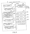
- Fig.3 shows in outline one of the sound-generating units S.
- an input interface 20, qualified as a MIDI receives data as performance-controlling messages in the invention, and delivers same to a signal-detecting circuit 21 to be detected thereby.
- a plurality of data as outputs from the signal-detecting circuit 21 are sorted to select some data necessary for the sound-generating units S.
- Fig.4 illustrates that each of the received data RCVD which are received by the signal-detecting circuit 21 comprises three bytes consisting of a first byte STAT, a second byte DAT1 and a third byte DAT2. These data are stored in a buffer included in the signal-detecting circuit 21. The thus stored data are charged to a microcomputer 22 through a bus 23 together with the total number of the received data BSTN under control by the microcomputer.
- the data which were referred to above as the necessary data for the sound-generating units S include, as shown in Fig.4, key-press data, key-off data, as well as damper data that relate to a damper which is pressed down to inhibit a damping processing. This damping processing would otherwise accelerate the damping of sounds, therefore the damper data are needed to prolong the period of decay.
- the buffer may further store, if necessary, after-touch data, program-changing data, control-changing data, mode-message data, and/or system-exclusive data if they are selected.
- the key-press and the key-off data as well as the damper-on and the damper-off data are binary coded.
- Each of the first bytes STAT of those data comprises four leading bits and four trailing bits “nnnn", “n” indicating signal-receiving channels.
- Seven trailing digits "kkkkkkk” in the second bytes DAT1 indicate ordinal numbers corresponding to key codes whereas the other seven trailing digits “vvvvvv” in the third bytes DAT2 indicate velocities.
- These components of data will hereinafter be simply called “n”, “k” and “v” if decimals are adopted to indicate them, and “n” may vary from 0 (zero) to 15 while “k” and “v” fall within a range of 0 (zero) to 127.
- the signal-detecting circuit 21 in the sound generating units S is, for the sake of convenience, regarded in this description to be capable of receiving signals through the signal-receiving channels 0 to 7 only, and incapable of receiving them through channels 8 to 15.
- the signal-receiving channels 0 to 7 are assigned to eight timbres or musical tones such as those of the piano, the harpsichord and so on.
- An operator of this system is instructed to make previous settings of a total-number switch TOTLSW 24A and a preferential-order switch PRIOSW 248, these switches constituting a components-in-total switch 24.
- the preset states of the switches TOTLSW 24A and PRIOSW 24B are detected by a switch-detecting circuit 25 so as to be charged to the microcomputer 22 as an incorporated-components data TOTL and as initial data PRIO of the preferential orders.
- the operator can employ a total number of the sound generating units S as such a data TOTL that is to be set on the switch TOTLSW 24A.
- the switch PRIOSW 24B can make use of the switch PRIOSW 24B to assign numerals from "1" to a higher ordinal to the respective sound generating units S, as the initial data of the preferential orders.
- the higher ordinal corresponds to the incorporated-components data TOTL, and assigning of such numerals has to be carried out sequentially not to involve any overlapping or doubling of the numerals between any two or more such units S.
- the microcomputer 22 is further charged with manually operable member data MNPh through a manually operable member detecting circuit 27, the data MNPh representing operated states of a group of manually operable members 26.
- These members 26 serve the purpose of switching over or adjusting the timbres and the generated volume of each musical tone. It is to be noted that all of the aforementioned data, namely the incorporated-components data TOTL, the initial data PRIO of preferential orders, and the manually operable member data MNPh, are those which indicate the states of related parts or components at the moment when they are charged to the microcomputer 22 for control of the system thereby.
- the microcomputer 22 itself comprises a central processing unit (CPU) 22A executing the predetermined programs, a read only memory (ROM) 22B storing the programs, a random access memory (RAM) 22C used as a working memory required for executing the programs and also as registers allotted to the received data RCVD, the incorporated-components data TOTL, the initial data PRIO of preferential orders, and the manually operable member data MNPh.
- the microcomputer further comprises a timer circuit 22D consisting of a group of timers or clocks that determine the times or moments during execution of the programs.
- a tone-generating circuit 28 having sixteen (16) tone-generating channels in the first embodiment is activated and controlled by executing the aforementioned programs by means of the received data RCVD, incorporated-components data TOTL, the initial data PRIO of preferential orders, and the manually operable member data MNPh. Desirable musical tone signals are produced respectively by the thus determined and assigned tone-generating channels.
- the manually operable member data MNPh is read from the manually operable member circuit 27.
- desired parameters corresponding to the aforementioned eight timbres are read from a predetermined table stored in the ROM 22B.
- the parameters are then converted into parameter groups GTEm(0) to GTEm(7) that are written into predetermined registers GTEm(0)R to GTEm(7)R, respectively.
- the parameter groups may be named GTEm(n) inclusively to indicate each parameter group that is allocated to the timbre which corresponds to the signal-receiving channel carrying the number "n".
- the received data RCVD each include the number "n" of signal-receiving channel. Accordingly, a musical tone for generating an audible sound is generated by using the parameter group GTEm(n) corresponding to the signal-receiving channel "n".
- each of the sound generating units S can generate various timbres under control by the ordinal number "n” carried by said signal-receiving channels.
- the incorporated-components data TOTL and the initial data PRIO of preferential orders are read from the switch-detecting circuit 25. These newly read data are then compared respectively with the previous incorporated-components data TOTL and the previous initial data PRIO that are on the register at that time when the read step is performed. The newly read data are written into registers TOTLR and PRIOR, if they differ from the previous ones.
- the registers TOTLR, PRIOR and PRIR are, as described above, already at their cleared states at the start of execution of the programs because the RAM 22C was cleared when power supply was turned on. Thus, the preferential order data PRI that are written into the other registers PRIR are automatically set to their initialized states to give the initial data PRIO of preferential orders.
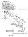
- the received data RCVD are read from the signal-detecting circuit 21, each of the data comprising the first byte STAT, the second byte DAT1 and the third byte DAT2. These data are written into respective corresponding areas of a register RCVDR, according to a sequence of time lapses taking place in such areas. Further, a total number BSTN of the received data RCVD is also read to be written into a register STNR as a total number STN of newly charged data that are to be processed.
- Step G Decision is made as to whether or not the processing of received data RCVD has finished, based on whether the total number STN of data to be processed is or is not "0" (zero) in the register STNR storing said data. If the number STN of the data to be processed is "1" or more indicating a state that the processing thereof has not yet been completed, then the process goes to Step G.
- Step E If, on the contrary, the number of STN of the data to be processed is judged to be "0" in Step E, then the processing of the received data RCVD is regarded as having finished. Accordingly, the process advances forward to sequentially perform the following envelope processings within respective envelope waveform-producing channels which correspond to the tone-generating channels, respectively.
- a predetermined table of envelope waveforms stored in the ROM 22B is read therefrom. Further, reference is made to the group of parameters GTEm(n) relating to musical tone generation and written in respective registers GTEm(n)R that correspond to respective signal receiving channels carrying the number "n". These numbers, in turn, are written in registers nR in accordance with the respective tone-generating channels. Furthermore, reference is also made to key codes KYC and touch response data KTD that are written in registers KYCR and KTDR as described later. Based on all of the foregoing parameters in this paragraph I), rates RT and break instant levels (levels at instants of discontinuity LBP are calculated and produced.
- Each rate RT shows a value of change in envelope per predetermined unit time ( and includes plus or minus sign according to increase ( swell ) or decay of envelope ).
- Each of the break instant levels LBP shows on the other hand the envelope level at the instant of change in the accumulated rate RT, in other words, at the instant when the slope of envelope changes.
- the rates RT and the break instant levels LBP constitute a group of rates RTj and a group of break instant levels LBPj, respectively.
- a table which is previously stored in the ROM 22B and corresponds to a graph as shown in Fig. 6 which represents a convertible relation between the touch response data KTD and attack levels LATK, in order to produce the attack levels LATK.
- the group of rates RTj, the group of break instant levels LBPj, and the attack levels LATK will hereinafter be called envelope parameters, inclusively.
- Envelope levels LEV that is, envelope waveforms
- Envelope levels LEV are calculated based on the predetermined group of rates RTj and the predetermined group of break instant levels LBPj which in turn are calculated as described above.
- Calculation of LEV is carried out as follows. From the group of break instant levels LBPj written in a register LBPjR, selected are those levels which correspond to envelope steps "j" written in a register jR, in order to be written into a register LBPR. Similarly, selected from the group of rates RTj written in a register RTjR are those rates which correspond to the envelope steps "j" written in the register jR, the selected rates being written into a register RTR.
- "0" is set to an envelope completion flag EV-END if a release part "R" is judged to have been completed, based on a decision made on whether the envelope level LEV has or has not become equal to a break instant level LBPend which corresponds to completion of the release part "R".
- the value "0" on the envelope completion flag EV-END releases the corresponding tone-generating channel.
- Every envelope waveform-producing channel is provided with all of the foregoing data each determined as described above and including the group of rates RTj, the group of break instant levels LBPj, the attack level LATK; the rates RT, the break instant levels LBP, the envelope levels LEV and the envelope steps "j" to be calculated; as well as the flags EV-AT and EV-END.
- registers RTjR, LBPjR, RTR, LBPR, LEVR, jR, EV-ATR and EV-ENDR are also owned by each of the envelope wave-form-producing channels in such a manner that they constitute one group and are treated with as such one group.
- a key-off envelope in-processing flag RKOF is set at "1" to be written into a register RKOFR thus urging a key-off processing ( i. e., Step M described later ) to start, and if at the same time "0"(zero) appears on a damper state flag FCDS(n) thereby indicating a damper pedal is not pressed down wherein the flag FCDS(n) is a flag written in a register FCDS(n)R corresponding to the ordinal number "n" of signal-receiving channels in the tone-generating channels, then the attack-part end flag EV-AT written in the corresponding register EV-ATR will indicate with signal "0" the completion of attack part "A", and thereafter the key-off envelope in-processing flag RKOF is reset at "0" to thereby change the envelope waveform into a predetermined key-off envelope.
- a manner of producing the key-off envelope is similar to that described in the former paragraphs.
- the process returns to Step B after the envelope processing.
- Step E If the total number STN of data to be processed is judged to be "1" at Step E thereby indicating that the processing of key operations has not yet finished, then "1" is subtracted from the number STN so as to produce a new number to be written into the register STNR. Subsequent to this procedure, the oldest received data RCVD in the register RCVDR is read therefrom first-in, first-out method ) so that a signal-receiving channel number "n” given at four trailing bits of the first byte STAT in the oldest data RCVD is written into a signal-receiving channel buffer BnR.
- the oldest data is either judged to be, or not to be, a damper data depending upon whether or not four leading bits of said first byte STAT has a value of "BH" ("H" denoting that "B” is a hexadecimal) on condition that the second byte DAT1 has a value of "40H". Therefore, if the four leading bits of first byte STAT do not have the value of "BH", or if the second byte DAT1 does not have the value of "40H", then the oldest received data is judged not to be a damper data and the process advances forward to Step I.
- BH "H" denoting that "B” is a hexadecimal
- Step G If, at the Step G, the four leading bits of first byte STAT as a whole are judged to have the value of "BH"( "H” also denoting hexadecimal), and concurrently the second byte DAT1 is judged to have the value of "40H", then the received data RCVD is judged to be a damper data whereby the process comes to this damping processing subroutine of Step H.
- the details this subroutine will be described later referring to the flow-chart in Fig.8.
- the process returns to Step E after the subroutine has finished.
- Step G If the received data RCVD is judged at Step G not to be a damper data, then the value "k" of the second byte DAT1 of received data RCVD is written into a register BKYCR as a key code "BKYC", and the value "v" of the third byte DAT2 is written into a register BKTDR as a touch response data BKTD.
- decision is made on whether the received data RCVD is or is not a key-off data, based on whether four leading bits as a whole of the first byte STAT in said data RCVD have a value of "8H". If said four bits have the value of "8H" indicating a key-off data, then the process goes to Step M.
- Step K In the case wherein the received data RCVD is judged at Step J to be a key-press data because the value of the third byte DAT2 is not "00H", decision is made on whether the preferential order data PRI stored in the register PRIR is or is not "1". If the preferential order data PRI is not "1", the process goes to Step N. A purpose of the decision made here at Step K is to prevent generation of the musical tone corresponding to the key-press data unless the preferential order data PRI is "1".
- Respective musical tones are assigned to the respective musical tone-generating channels by writing predetermined data into musical tone-allocating channels each corresponding to the former channels, and in particular by writing them into a key state flag KYS, the key code KYC, the touch response data KTD, a pitch data FQY and a group of musical tone or timbre parameters TNp.
- numeral "1" which is carried by the key state flag KYS and indicates a pressed state of key is written into a register KYSR, and a value carried by a register BKYCR is written into the register KYCR as the key code KYC.
- a value carried by the register BKTDR is written into the register KTDR as the touch response data KTD.
- Furthermore, written into a register FQYR are the pitch data FQY that are calculated and produced from the group of parameters GTEm(n) that relate to generation of musical tones and are written in registers GTEm(n)R corresponding to the signal-receiving channel number "n" carried by the signal-receiving channel buffer BnR wherein the key codes KYC written in the register KYCR are also utilized in such a calculation.
- Step N If a tone-generating channel is found which has finished generation of a previous tone and is released at an instant when the following detection is performed, then this tone-generating channel is assigned again to a next musical tone in the aforementioned manner and the process goes to Step N.
- the detection is carried out by checking the states of key state flags KYS written in the registers KYSR for the musical tone-allocating channels and also by concurrently checking the states of envelope completion flags EV-END written in the registers EV-ENDR for the envelope waveform-producing channels.
- search is performed to find out such a tone-generating channel which is generating a tone at the lowest envelope level LEV after completion of its attack part A.
- the search is conducted by checking the state of envelope levels LEV written in the registers LEVR of the waveform-producing channels, and by concurrently checking the state of attack-part end flags EV-AT written in the registers EV-ATR of the waveform-producing channels.
- the tone-generating channel found by such a search is assigned to generate the next musical tone and the process goes to Step N.
- the register LEVR is reset to cease generation of the musical tone in this case, but a processing causing an accelerated attenuation will be more desirable.
- the received data RCVD is a key-off data if it proves in the decision in Step I to have the value of "8H" as to four leading bits in the first byte STAT, or if it proves in the decision in Step J to have the value of "00H” as to its third byte DAT2.
- the following key-off processing is executed on such a received data RCVD.
- a key code BKYC which is included in a key data BKYD written in a register BKYR, and to a signal-receiving channel number "n” written in a signal-receiving channel buffer BnR.
- the key-off envelope in-processing flag RKOF is set "1" showing that key-off envelope processing is taking place, and the value of the key state flag KYS is changed to "0" showing a key-off state so as to command initiation of the key-off processing.
- the process then returns to Step E.
- This step is a preferential order-shifting subroutine which will be described later in detail referring to Fig. 9.
- the process returns to Step E after this subroutine has finished.
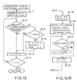
- Step H The damping processing subroutine (Step H) will now be described in detail with reference to Fig. 8 in a step-by-step manner.
- Step H-1 Decision is made as to whether or not a value of the third byte DAT2 which is included in the received data RCVD written in the register RCVDR is less than "40H". If the value of the third byte is less than "40H", then the process goes to Step H-3.
- Step H-2 If in the Step H-1 the value of third byte DAT2 is judged not to be less than "40H” with the received data RCVD corresponding to a state of damper "ON” ( i.e., damper pedal being pressed down ), then value "1" borne by the damper state flag FCDS(n) to indicate a pressed down damper pedal is written into the register FCDS(n)R which corresponds to the signal-receiving channel number "n” written in the signal-receiving channel buffer BnR, thus ending here this subroutine.
- third byte DAT2 is less than "40H” with the received data RCVD corresponding to a state of damper "OFF" (i.e., a damper pedal being released ), then "0" borne by the damper state flag FCDS(n) to indicate a damper pedal not pressed down is written into the register FCDS(n)R , which corresponds to the signal-receiving channel number "n” written in the signal-receiving channel buffer BnR, thus ending here this subroutine.
- Step N The preferential order-shifting subroutine ( Step N ) will now be described in detail with reference to Fig. 9 in a step-by-step manner.
- New preferential order data PRI are produced by adding "1" to the old preferential order data PRI and written into the registers PRIR.
- the subroutine just described above is so designed that the preferential data PRI are incrementally increased each time the key-press data is received, whereby any preferential data PRI which has exceeded the incorporated-components data TOTL is reset at "1".
- the preferential order data PRI which are assigned thereto change their values upon each receipt of key-press data as shown in Fig.10. Only such a sound-generating unit S for which the value of preferential order data PRI is set at "1" at a given instant does generate sound on the basis of judgment that the key-press data received at that instant is valid.
- all of the incorporated sound-generating units S can generate sounds in turn such that none of them is allowed to generate sound more frequently than the remaining ones do, thus equalizing all the sound-generating units S with respect to the number of sounds generated.
- the number of sounds actually generated at each instant is kept equal to the number of incorporated sound-generating units S, no matter what key codes may be received, thus providing a sufficient effect of increasing the effective sources of sounds.
- the initial values PRIO of preferential orders may be reset as the preferential order data PRI onto the registers PRIOR in the event that all the keys were released.
- This arrangement will be useful for re-normalization of preferential orders which might become out of order occasionally due to alterations made by a user of this system on the incorporated-components data TOTL or on the initial values PRIO of preferential orders.
- the incorporated-components data TOTL as well as the initial values PRIO of preferential orders may be input to and written into the microcomputer 22 by means of the input interface 20 without using the components-in-total switch 24.
- the so-called daisy chain may be employed to establish a mutual communication link between the incorporated sound-generating units S which are connected to each other by means of the MIDI.
- a data relating to such connections may, in this communication link, be sent successively from one to another sound-generating unit S so as to enable an automatic detection of the incorporated-components data TOTL by themselves thereby to set up automatically the data TOTL and the initial values PRIO of preferential orders.
- the signal-receiving channel numbers "n" are predetermined for respective timbres in the first embodiment, said numbers "n” may be assignable to the timbres at user's discretion. And in such a case, the same signal-receiving channel may be allotted to each sound-generating unit S as to one and the same timbre. Another total number of timbres may be adopted instead of eight (8) set up beforehand in the first embodiment.
- the user may choose any initial value PRIO of preferential orders to activate from time to time the sound generating units whose preferential order data PRI is judged to correspond to the chosen value PRIO.
- All of the preferential order data PRI of all the sound-generating units S should, in such a case, be selected beforehand such that they are cleared up at the same time when the power supply is turned on or all the keys are released.
- the initial values PRIO may be set up mechanically, for instance by means of a rotary switch or anything else, instead of charging them to the RAM 22C to be stored therein.
- the system in the first embodiment comprises merely such sound-generating units S that cannot receive the signals from the signal-receiving channels No. 8 to No.15 but can receive those from the channels No.0 to No. 7.
- a group "A" consisting of three sound generating units S may be assigned to the signal-receiving channels No.0 to No.7 whereas another group "B" consisting of the other three sound-generating units S′ are assigned to the channels No.8 to No.15.
- numeral "3" as the incorporated-components data TOTL together with other numerals "1", “2" and “3" as the sequential initial values PRIO of the preferential orders are allotted to the former group "A" of the units S.
- allotted to the latter group "B” of the units S′ are similar initial values PRIO of preferential orders, whereby note-on messages to the signal-receiving channels No.0 to No.7 cause the group "A" of sound-generating units S to generate sounds sequentially while the other note-on messages to the channels No.8 to No.15 causing the group "B" of the sound-generating units S′ to generate sounds.
- the first invention is applied to the first embodiment in which a musical tone-generating circuit is installed in each sound generating unit.
- the systems may be modified in such a manner that the performance controlling messages are selected to be supplied to a plurality of outside musical tone-generating circuits.
- This embodiment is adapted to the processing of consecutive depressions of one and the same key in such a system as in the first embodiment in which, as described hereinbefore, a plurality of sound-generating units are incorporated in combination to increase the total number of generated sounds per unit period of time.
- the consecutive depressions just referred to above mean that a key is depressed again to generate a new key-press data for a musi cal tone or sound in order to superpose this sound upon an old sound that has been and still being generated according to an old key-press data by a previous depression of the same key.
- the second embodiment relates to such sound-generating units S which generate sounds of a decaying type ( percussive type ).
- a scheme of the sound generating units S in this second embodiment is also given in Fig. 2 and thus is of almost the same nature as is those in the first embodiment. However it differs from those in the first embodiment in that a tone-generating circuit 28 has thirty two (32) tone-generating channels.
- each musical tone or sound generated in the second embodiment is composed, as is a sound generated by the piano, of (a) a first constituent tone A and (b) a second constituent tone (B) following the first constituent tone A.
- the first constituent tone A mainly corresponds to an initiation part of the tone (i.e., an attack part "A" plus a decay part "B" in ADSR representation as shown in Fig. 7 ), the initiation part composed of a key-hammering sound and a string-striking sound which is generated immediately after the striking of a string and has a higher content of harmonic components.
- the second constituent tone B mentioned above mainly corresponds to a continuing part (i.e., a sustain part "S” plus a release part "R” ) which gives a feeling of generated volume of the tone, and consists of a string sound which has a lower content of harmonic components and a lesser degree of change in timbre. It is also assumed in the second embodiment that, in order to produce each musical tone signal, the first constituent tone A and the second constituent tone B are respectively generated in different tone-generating channels.
- the tone generating circuit 28 comprises thirty two (32) tone-generating channels wherein a first and a second channel constitute a group, a third and a fourth channel constitute another group, and so on ---, then a thirty first and a thirty second channel constitute a still further group.
- Each of the tone-generating channels carrying even ordinal numbers is assigned to the first constituent tones whereas each of the tone-generating channels carrying odd ordinal numbers is assigned to the second constituent tones so that they respectively produce musical tone signals.
- Each of the tone-generating units S constructed as above in the second embodiment executes a basic program as represented by a flow-chart shown in Fig. 11. Differences between each step in the second embodiment and each corre sponding step in the first embodiment will now be explained in detail.
- Step F′ In addition to the procedure I) of Step F in the first embodiment, calculated and produced here based on a group of parameters GTEm(n) relating to generation of musical tones is a first variation rate RTS which indicates minus variations per unit time in changing the envelopes.
- the first variation rate RTS is also one of the envelope parameters and is set up for each envelope waveform producing channel. Therefore, a register RTSR is provided for each envelope wave-form producing channel in order that the first variation rate RTS is written into and read from the register RTSR.
- Attack levels LATK are produced by means of a conversion table which has been stored in a ROM 22B corresponding to and based on a touch-response datum-attack level conversion graph shown in Fig. 12 instead of that shown in Fig. 6.
- Step K′ This step differs from Step K in that a content of a register BCHR is cleared so that assigned-channel numbers BCH in this register are reset at their initial states, indicating no channel numbers assigned, before the decision in Step K is made.
- Step L′ A difference between this step and Step L in the first embodiment is as follows.
- Assignment to musical tone-generating channels is performed similarly to that in the fist embodiment but to the groups respectively consisting of: the first and the second channels; the third and the fourth channels; -----; and then the thirty-first and the thirty-second channels.
- the assignment comprises the writing of said first variation rates RTS into the register RTSR in addition to the procedures of Step L in the first embodiment. Commands are given to each group of the tone-generating channels to commence generation of musical tones, and the channel numbers to which the second constituent tones B were assigned are, as the assigned-channel numbers BCH, written into the register BCHR.
- Step N′ reset are those timers TST which count up time lapses are the assignment of musical tones are reset, the timers being written into registers TSTR which are installed within a timer circuit 22D according to the musical tone-allocating channels. Then, the process goes to Step N′.
- Step M′ This step is identical with Step M in the first embodiment.
- Step N′ Although the content itself of this step is identical with the preferential order-shifting subroutine in Step N of the first embodiment, the process in this second embodiment goes to Step O after completion of Step N′.
- Step P In a case wherein the decision in Step P affirms the initiation of the changing processing and the occurence of the consecutive strikes based upon "1" appearing on the consecutive-strike detecting flag DMPF, the process will begin a consecutive-strike processing routine. This consecutive-strike processing routine will be described later in detail referring to a flow-chart shown in Figs. 14A and 14B.
- Step O the consecutive-strike detecting routine
- the detecting of consecutive strikes is performed as to the second constituent tones B and by searching musical tone-generating channels which are actually generating musical tones caused by the same key.
- Initialization is carried out by setting to "1" the number of loops "i” written in a register iR, by setting to “0” the consecutive-strike detecting flag DMPF, wherein "0" indicates a state that any consecutive strikes are not detected, and by setting to "0” a total number “e” of old key-presses subject to the consecutive-strike processing, which number "e” is written in a register eR.
- the number of musical tone-generating channels N being thirty-two in the present embodiment, which number is stored in the ROM 22B, is compared with the number of loops "i" written into the register iR, and if the number of loops "i" is not larger, the process returns to Step O-2 in a repeated manner, and if the number of loops "i" is larger, no consecutive strikes exist corresponding to all musical tone-generating channels, and therefore the routine is ended.
- Step O-5 Where the key code BKYC of the new key-press and the key code KYC are the same in the decision in Step O-2, and besides, the signal-receiving channel numbers are identical with each other, then a decision is made as to whether or not the number of loops "i" coincides with the assigned-channel number BCH written in the register BCHR. If the number of loops "i" and the assigned channel number BCH are the same, the musical tone-generating channel of the number of loops "i" has been already assigned in Step L′ and already judged to correspond to the consecutive strikes. Therefore, this is excluded from the data which are undergoing the present detecting routine, and the process goes to Step O-3.
- the musical tone-generating channel which related to the accelerated attenuation, is also excluded from the data which are undergoing the present detecting routine.
- Step O-3 After completion of the present routine, indicate a total number of old key-presses that has been treated with as those included in the consecutive strikes. However, during the present routine, the value “e” shows the “e”th tone-generating channel among those channels allotted to the old key-presses that have been detected to be included in the consecutive strikes. Furhter, "1" is set at the consecutive-strike detecting flag DMPF in order to indicate that the conssecutive strikes have been detected, and is then written into the register DMPFR. The process goes to Step O-3 after Step O-6 has ended.
- a search is made along all the tone-generating channels, by means of the second constituent tone B, for a musical tone-generating channel which is generating an effective tone and which corresponds to the same timbre which has been assigned to the same signal-receiving channel, and the channel number of that musical tone-generating channel is written into the register AOCH(e)R as the channel number AOCH(e) of the old key-press, and the consecutive-strike detecting flag DMPF is set to "1" showing that the consecutive strikes have been and are being detected.
- tone-generating channel that corresponds to a tone generation of a shortened duration due to the command which has ordered an initiation of the accelerated attenuation in the consecutive-strike processing, is excluded from the tone-generating channels to be treated as above.
- Step Q the consecutive-strike processing routine
- Fig.14 which is made up of Figs. 14A and 14B.
- the second constituent tones B of the old key-presses are assigned to such tone-generating channels which are to be treated by this consecutive-strike processing routine, and which have been detected in the consecutive-strike detecting routine (Step O) and have the channel numbers AOCH(e) of old key-presses written into the register AOCH(e)R.
- the following processing relates to registers which are installed for the second constituent tones B of old key-presses and which correspond to those tone-generating channels which bear the channel numbers AOCH(e) written in the aforementioned registers AOCH(e)R.
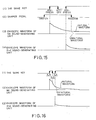
- the tone generating unit S which has generated sound in response to the first key-depression would not generate sound at an instant when the second key-depression were given as to the same key, because a key-off state appears at that instant for the unit S after the first key-depression.
- the musical tone generated by the first key-depression would suddenly die away in an unnatural manner ( as indicated at the broken line on an envelope waveform of the musical tone generated by the first unit S, in Fig.15, (3) ).
- the musical tone-generating channel is recovered to its key-depression state if this channel is at key-off state when the consecutive strikes are detected, whereby such a quick decay is avoided even if the damper pedal were released in the aforementioned manner.
- Step Q-3 A decision is made as to whether or not a damping processing is inhibited by a continuing depression of the damper pedal when the key is released. This decision is based on the damper state flag FCDS(n) written in the register FCDS(n)R which corresponds to the signal-receiving channel "n" written in the signal-receiving channel buffer BnR.
- the process goes to Step Q-8 if the damping processing is judged to be inhibited due to "1" on the damper state flag FCDS(n) showing that the damper pedal is depressed (i.e., "Damper ON" ).
- Step Q-6 where, in the decision in Step Q-5, the envelope LEV of the second constituent tone B of the old key-press is not larger than the predetermined break instant level LBPj corresponding to the envelope step "j", then "1" is added to the envelope step "j” to produce a new value of the envelope step "j” written thereafter into the register jR, and the process returns to Step Q-5.
- Step Q-7 where, in the decision in Step Q-5, the envelope level LEV of the second constituent tone B of the old key-press is larger than the predetermined break instant level LBPj corresponding to the envelope step "j", then this break instant level LBPj is written into the register LBPR, the rate RTj is written as the rate RT into the register RTR, and thereafter the process goes to Step Q-20.
- Steps Q-4 to Q-7 are those which change the envelope of the musical tone in its released state into the envelope of sustain state, based on the current envelope level LEV.
- This treatment simulates a phenomenon that a new key-depression releases a string damper thereby re-initiating a long-lasting decay process if the new key-depression is made before the musical tone which has been generated by the old key-depression has completely died away.
- a weaker key-depression made immediately after a stronger key-depression, as shown in Fig. 16 will not cause an incongruous and sudden decay of the musical tone.
- Step Q-8 where, in the decision in Step Q-3, the damper state flag FCDS(n) indicates "1" showing that the damper pedal is not depressed (i.e., "Damper 0N" ) and therefore the damping processing is inhibited, the simulation of the envelope of the second constituent tone B is performed on the supposition that a new key-depression was made, and the generated volume WOL of the second constituent tone B of the old key-press as well as a residual generated volume WEL of said second constituent tone B.
- the abovementioned simulation is such a treatment that the envelope parameters necessary for production of the predetermined envelope waveform are calculated at high speed to follow a process of generation of the envelope waveform, based on the key code BKYC (KYC) and touch-response data BKTD (KTD) read from the table in ROM 22B, and also based on the parameter groups GTEm(n) concerning the generation of musical tone and corresponding to the signal-receiving channel No. "n" which is written in the register nR which corresponds to the second constituent tone B to be processed.
- KYC key code
- KTD touch-response data
- T1 The time lapse from musical tone assignment of a new key-press to an instant when the attack part "A" has completed as to the envelope waveform of the second constituent tone B by the new key-press.
- T2 The time lapse from musical tone assignment of the old key-press to musical tone assignment of a new key-press.
- the time lapse T1 is evaluated by simulating the envelope waveform of the second constituent tone B; and the time lapse T2 is obtained by reading the instantaneous value of the timer TST, the value having been counted from the assignment of the old key-press and having been written into the corresponding register TSTR. )
- the generated volume of the second constituent B of the old key-press after the new key-press (such a generated volume being the "residual generated volume” referred to as WEL ) is decreased to a value of the generated volume WOL of the second constituent tone B of the old key-press that is multiplied by a "residual" factor KD.
- WEL WOL x KD
- the residual factor KD differs depending upon the way of striking the tone-generating body, the amount of damping of the tone-generating body, the strength of the strike and the like, namely, the key code BKYC(KYC), touch response data BKTD(KTD) and manually operable member data MNPh.
- the key code BKYC(KYC) the key code
- touch response data BKTD(KTD) touch response data
- MNPh manually operable member data
- the residual factor KD differs depending upon the strength of touch (key-press).
- the amount of damp ing of the strings differ depending on the tone pitch or the acoustic-wave frequencies of the strings.
- the residual factor may be changed by the tone pitch and the interval of key-presses. Or, to make the mechanism simple, random elements can be added. Also, since the effect given differs depending upon the degree of higher harmonics, the residual factor may be changed on a constituent tone basis when the constitution is made with a large number of constituent tones.
- KD 0.9 is employed to simplify the processing.
- the envelope level WLEV of the changed second constituent tone B of the old key-press is larger than the instantaneous envelope level LEV, that is, the changed second constituent tone B has not yet passed through the attack part "A"
- the envelope parameters of the second constituent tone B are calculated based on touch response data WKTD of the changed second constituent tone B of the old key-press in order to cause the envelope of second constituent tone B to correspond to the residual generated volume WEL thereof, in the following manner.
- the touch response data WKTD of the changed second constituent tone B of the new key-press is obtained by converting the attack level WATK of the changed second constituent tone B of the old key-press, in that an inversive conversion table is stored in advance in the ROM 22b in accordance with the touch response data KTD- attack level LATK conversion graph. And, the envelope parameters are calculated making use of the thus obtained touch response data WKTD.
- Step Q-17 a decision is made as to whether the envelope level WLEV of the changed second constituent tone B of the old key-press written in the register WLEVR is or is not larger than the predetermined break instant level LBPj which is written in the register LBPjR corresponding to the envelope step "j" written in the register jR.
- the process advances forward to Step Q-19, if said envelope level WLEV of the changed second constituent tone B of old key-press is larger than said predetermined break instant level LBPj.
- the above-described consecutive-strike processing routine is such that the envelope waveform is simulated as to the second constituent tone B of the old key-press and the residual generated volume WOL thereof is calculated so that the envelope of said second constituent tone B is changed, corresponding to said residual generated volume.
- the principle of said routine resides in a processing in which the second constituent tone B produced by a key is used to search for a musical tone-generating channel which is actually generating a musical tone based upon the same key, whereby a consecutive strike of the key is detected to change the envelope.
- the predetermined first variation rate RTS is used to avoid an intricacy of description. It is however more desirable to calculate and determine such a rate that the envelope comes to the next break instant LBP after the time lapse of T1 ( see Step Q-8 ).
- the musical tone is generated in a manner as shown in Fig. 17 in a case wherein the envelope level WLEV of the changed second constituent tone B of old key-press is not larger than the instantaneous envelope level LEV.
- the musical tone will be generated in a manner as shown in Fig. 18 in a case wherein the envelope level WLEV of the changed second constituent tone B of old key-press is larger than the instantaneous envelope level LEV.
- Figs. 17 and 18 there is shown a system in which a musical tone based on a new key-depression is generated by one sound generating unit S that is combined with the other sound generating unit S which has been generating a preceding musical tone.
- a second constituent tone B of the new key-depression is not illustrated in Fig. 18 in order to avoid intricacy.
- the rectangular waves at the bottoms in Figs. 17 and 18 denote the key-press and the key-off operations performed on the same key to provide the previous and the new key-depressions.
- the steps may be omitted which would otherwise be needed when the damping processing is not inhibited due to the damper state flag FCDS(n) indicating "0" to show that the damper pedal is not depressed ( i. e., Damper OFF ) in the decision at Step Q-3.
- the Steps Q-4 to Q-7 may be omitted before the process goes to Step Q-20.
- the treatment for changing the residual generated volume may be executed whatever position the damper pedal may be in. In this case, the process is caused to go to Step Q-8 directly from Step Q-2 thereby by-passing Steps Q-3 to Q-7.
- the musical tones generated according to the second embodiment have, as illustrated in Fig. 19, a composite waveform which is integrated from a waveform of the first constituent tone A and a waveform of the second constituent tone B.
- Fig. 20 gives a logarithmic representation of these waveforms wherein the envelope waveform of the second constituent tone B has a constant rate of change per unit time in the course of time, on and after the decay part "D". Therefore, the same key-presses are deemed to provide such second constituent tones B which have envelope waveforms similar to each other in their shapes on and after said decay part "D".
- the second embodiment of the invention employs, as described hereinbefore, the pairs of musical tone-generating channels, each of the pairs comprising one tone-generating channel assigned to the first constituent tone A and the other assigned to the second constituent tone B.
- pairs have not necessarily to be employed, and instead said tones can be assigned separately to non-paired tone-generating channels since the channels assigned to the tone A are freed earlier than the other channels assigned to the tone B, as apparent from Fig. 20.
- Such a system will make it possible to utilize more effectively the musical tone-generating channels.
- All the sound generating units S may, in such a case, be set to an "Omni-Mode-ON" as defined in the MIDI standards wherein all the data ( performance controlling messages ) are read to sequentially generate musical tones each time the keys are depressed while the preferential orders are concurrently changed.
- converting apparatuses of such a kind that they respectively and exclusively receive the data corresponding to predetermined signal-receiving channels in order to convert the data, before transmitting them to said sound-generating units S, into those which do not include any informations relating to said signal-receiving channels.
- the sound-generating units S in such a case are therefore controlled to generate sounds by such data lacking the informations relating to the signal-receiving channels.
- tone quality or timbre of the continuing portion of the musical tone generated is enriched.
- this portion is composed of second constituent tones B1 and B2.
- higher harmonic components of the continuing portion at a heavy strike are strong and the envelope is relatively short.
- higher harmonic components of the continuing portion at a light strike are weak and the envelope is relatively long, as will be explained below.
- the musical tone-gener ating circuit 28 is composed of forty-eight musical tone-generating channels from a first channel to a forty-eighth channel.
- the first channel to the third channel, the fourth channel to the sixth channel, .... , the forty-sixth channel to the forty-eighth channel form combinations (trios) generating desired musical tones, respectively.
- the second constituent tone B2 is assigned to the first channel, the fourth channel, Vietnamese , the second constituent tone B2 is assigned to the second channel, the fifth channel, .... , and the first constituent tone A is assigned to the third channel, the sixth channel, .... , to produce musical tone-signals, respectively.
- Consecutive strikes of one key are detected by searching for a musical tone-generating channel which is actually generating the second constituent tone B2 caused by the same key.
- the envelopes are changed, based on the sum of generated volumes of the second constituent tones B1 and B2.
- "3" instead of “2” is added to the number of loops "i" in the consecutive-strike detecting routine at Step O-3.
- each tone-generating channel produces an integral musical tone which is not divided into such a first and a second constituent tones A and B as in the second embodiment.
- musical tones generated here have, as illustrated in Fig. 19, a composite waveform which is integrated from a waveform of the first constituent tone A and a waveform of the second constituent tone B.
- a difference from the second embodiment is that "1" is added the number of loops "i” in place of adding "2" thereto in Step O-3 of the consecutive-strike detecting routine.
- Step Q-8 of the consecutive-strike processing routine the generated volume WOL of of the second constituent tone B to be generated by the old key-press is calculated by adding the envelope level of the first constituent tone A to an evaluated multiple of the envelope level of the second constituent tone B.
- Said envelope level of the tone A is obtained from the envelope level LEV of a musical tone (composite tone) which is to be generated here, by making use of a conversion table or the like which corresponds to the envelope waveform graph given in Fig.19.
- Said evaluated multiple is obtained by multiplying the residual factor KD by the further envelope level of the second constituent B, the further envelope level in turn being also obtained from said envelope level LEV by using the conversion table in the same manner as just described above.
- the generated volume WOL of the second constituent tone B to be generated by the old key-press may be replaced by the envelope level LEV of the musical tone ( composite tone ) generated.
- the tone of the initial portion and the tone of the continuing portion are contained at different ratios in the first and the second constituent tones A and B, instead of composing a musical tone from said first and second tones per se.
- a musical tone generated as shown in Fig. 22 consists of first and second constituent tones A′ and B′.
- the first constituent tone A′ which is not varied excessively in tone quality by the strength of touch and constitutes mainly the initial portion of a light key-depression, con tains a small quantity of higher harmonic components and gives a round feeling.
- the second constituent tone B′ is large at a heavy touch and constitutes mainly the continuing portion of a heavy key-depression which, in the case of a piano, contains a large quantity of higher harmonic components and gives a hard feeling.
- Fig. 23 shows a touch response data KTD-attack level LATK giving a relationship between the touch response data KTD and the attack level LATK, which relationship is equivalent to that given in Fig. 12. Accordingly, the constituent tone B′ is not generated at a light key-depression, and the first constituent tone A′ dominates the musical tone.
- Step Q-8 of the consecutive strike processing routine the generated volume WOL to be generated by the old key-press is obtained by adding such a generated volume of the first constituent tone A′ to such a generated volume of the tone B′ as respectively described in the Modified Example 2.
- the ratio of one constituent tone to the other constituent tone is variable so that the resulting musical tone also may be varied.
- the sounds of decaying or percussive types may include of course those sounds such as drumbeats which are generated by consecutively striking one and the same tone-generating means (e.g., membrane or other struck surface ), in addition to those generated by the keyboard apparatus.
- the present invention is applicable to the processing in the case wherein the musical tone are generated by the manually operable members, for instance the so-called key switch or the like so as to be superposed one on another, in such a manner as in an electronic drum machine system, a rhythm machine system or the like.
- the musical tone are generated by the manually operable members, for instance the so-called key switch or the like so as to be superposed one on another, in such a manner as in an electronic drum machine system, a rhythm machine system or the like.
- the present invention is applicable also to a performing apparatus system such as a rhythm machine system or an automatic performing or accompanying apparatus system which can store or program performance, automatically perform or automatically accompany wherein the same musical note is repeated in a superposed manner, if the key-press/off information generated by key-press/off operations in the embodiments are converted into such key-press/off information or equivalent thereto as generated in the performing apparatus just described above, or are changed into other information corre sponding to processings peculiar to the performing apparatus just described above.
- a performing apparatus system such as a rhythm machine system or an automatic performing or accompanying apparatus system which can store or program performance, automatically perform or automatically accompany wherein the same musical note is repeated in a superposed manner, if the key-press/off information generated by key-press/off operations in the embodiments are converted into such key-press/off information or equivalent thereto as generated in the performing apparatus just described above, or are changed into other information corre
- the audio system i.e., the amplifier 13 and the loud-speaker 14
- the audio system was described as a single system adapted to integrally output the inputs from the combined sound-generating units S and S′
- a plurality of audio systems which comprise loud-speakers spaced apart from each, other whereby sounds are emitted in a flip-flop like manner from sound sources positioned at different locations each time the key is depressed, thus giving a peculiar auditory effect.
- the data of preferential orders may be divided into groups separately supplied to each incorporated signal-receiving channels, i. e., timbres.
- the performance message generating apparatus may be a keyboard apparatus (the so-called “mother keyboard”) lacking sound generating units, the manually operable members being actually operated by a user to generate performance messages in the electronic drum apparatus or rhythm machine, and the sequencer or the likes which automatically generate performance messages for the automatic performing or accompanying apparatuses.
- the performance messages produced in the keyboard part may be transmitted to an outside sound generating unit in order to generate sounds besides those generated by the internal sound-generating units so that the total number of sound sources is increased.
Landscapes
- Physics & Mathematics (AREA)
- Engineering & Computer Science (AREA)
- Acoustics & Sound (AREA)
- Multimedia (AREA)
- Electrophonic Musical Instruments (AREA)
Abstract
Description
- The invention relates to systems of electronic musical instruments, such as an electronic keyboard instrument, an electronic drum apparatus, a rhythm apparatus, an automatically performing apparatus, an automatically accompanying apparatus, or the like. In particular, the invention relates to a technology by which sound-generating units in such electronic musical instruments are caused in sequence to generate musical tones, as well as to a further technology for processing a succeeding additional "note-on" signal that is input to said electronic musical instruments after the preceding same musical note has been input thereto so that the same musical tones are superposed one on another.
- Each of the musical tone-generating apparata that are currently known has only a limited number of, for instance sixteen, tone generators. Accordingly, in such electronic musical instruments of this type, there will occur a shortage of generated musical tones in case of simultaneously playing many sounds at the same time while a hold pedal is pressed down. In other words, some tones are not generated, or unwantedly decay or die away quickly in such a case.
- The so- called musical instrument digital interface (MIDI) is widely employed in electronic musical instruments so as to transmit tone-generating control data between apparatus units included therein. The MIDI has therefore given rise to a new system of electronic musical instruments such that a tone data-generating apparatus is coupled with a plurality of tone-generating apparata by means of the MIDI. In this case, some additional tone-generating apparata can be added to the existing ones and connected by the MIDI to the tone data-generating apparatus in order that a possible insufficiency in the number of sound sources may be complemented
- Also proposed already is another electronic musical instrument system in which one keyboard apparatus is connected with each of two musical tone-generating apparata (A) and (B) by means of the MIDI wherein note signals carrying odd code numbers are selectively received by one apparatus (A) whereas the other note signals carrying even code numbers are selectively received by the other apparatus (B). According to this system, a series of tone control data are divided into two groups which are respectively supplied to the tone-generating apparata (A) and (B), resulting in an increase of the numbers of musical tones generated simultaneously because there is practically no chance of the keyboard apparatus being operated only for the musical notes carrying the odd numbers or only for those carrying the even numbers. These note signals from the tone-generating apparata (A) and (B) are processed by a common amplifier and are output through a common loud-speaker.
- On the other hand, in another known system, if a succeeding second note-on signal for a musical note is to be fed to a tone-generating apparatus to which a preceding first note-on signal has been fed as to the same musical tone in order to superpose these same musical tones one upon another, then the second signal is assigned to a musical tone-generating channel different from the tone-generating channel to which the first tone was assigned.
- Subsequent to said processing in the known system, a sound of the tone which is being produced in response to the preceding note-on signal is damped quickly upon initiation of the tone generation corresponding to the assignment of the second note-on signal to the tone-generating channel.
- In the known system, however, the notes corresponding to the even-numbered note-on signals take place more frequently or less frequently than the notes corresponding to the odd-numbered note-on signals. Thus, one of the tone-generating apparata is likely to be activated more times to produce more musical tones than the other whereby a balance of activation times between the tone-generating apparata is hardly ensured.
- In musical instruments of the kind in which each note decays or dies away, each tone is generated by striking a tone-generating body (string, diaphragm or the like). Accordingly, when the tone-generating body which has generated a musical tone generates the same musical tone again in a superposed manner, the previously generated tone is weakened when the tone-generating body is struck again and a newly generated tone is added.
- Taking the piano for an example, where successive strikes are made so as to superpose the same musical tone, a string which is still vibrating following the previous key-depression, is struck again by a hammer, the vibration caused by the previous key-depression is partially damped by contact with the hammer, and energy generated by the new key-depression is added.
- However, in such a case as referred to above wherein the subsequent notes of the same tone are simply individually assigned to the different tone-generating channels, the generated volume of said tone is unwantedly increased, thereby causing somewhat of a problem.
- This problem may be eliminated by the system in which, as also referred to above, the tone generated by the previous note-on signal is damped upon initiation of the generation of a tone caused by the subsequent note-on signal. However, there arises another problem in that the tone is quickly weakened to an undesirable degree when the second musical tone taking place based on the subsequent note-on signal superposed on the first musical tone taking place based on the previous note-on signal has a smaller generated volume (amplitude) than the earlier first tone.
- It is therefore an object of the invention to provide an electronic musical instrument system including tone-generating apparata, in which system all of the said apparata are activated in an averaged manner to generate musical tones, and utilized in such an effective manner that available number or kinds of the simultaneously generated tones can be increased to a maximum which is equal to a total number of tone generators included in said apparata.
- It is another object of the invention to provide such an electronic musical instrument system that a generated volume of musical tones does not increase unwantedly nor are the tones weakened suddenly, whereby the two successive musical tones thus generated are slurred together naturally without giving sense of incongruity.
- It is still another object of the invention to provide an electronic musical instrument system in which simulation is carried out with high fidelity when the same musical tones are generated to be superposed one upon another.
- With a view to achieving the objects mentioned above, the system in accordance with the invention has characteristic features comprising:
at least one performance message-generating apparatus; and
a plurality of sound-generating units each adapted to receive performance-controlling messages from the performance message-generating apparatus;
wherein each of said sound-generating units comprises:
recording means for recording preferential orders that determine a sequential order by which said sound-generating unit receives the performance-controlling messages,
selecting means for selecting the performance-controlling messages to receive same in accordance with the preferential orders recorded in the recording means; and
tone-generating means for generating musical tones based on the performance-controlling messages that have been received by the selecting means. - Thus, the sound-generating units are caused to generate sounds in accordance with the selectively received performance-controlling messages which are given to said units according to the preferential orders arranged in circulative sequence. Therefore, a good balance is provided between the sound-generating units because their opportunities to generate sounds are well equalized without any marked unevenness in their times of the generating of sounds.
- Also in order to achieve the objects mentioned above, the system of electronic musical instruments in accordance with the invention has characteristic features comprising:
at least one performance message-generating apparatus; and
a plurality of sound-generating units each adapted to receive performance-controlling messages from the performance message-generating apparatus;
wherein each of the sound-generating units comprises:
recording means for recording preferential orders that determine a sequential order by which said sound-generating unit receives the performance-controlling messages;
selecting means for selecting the performance-controlling messages to receive same in accordance with the preferential orders recorded in the recording means;
tone-generating means having musical tone-generating channels and causing same to generate musical tones based on the performance-controlling messages that have been received by the selecting means;
first detecting means for detecting whether or not a second musical tone to be generated which is assigned by a new note-on message to musical tone-generating channels in the tone-generating means and a first or previous musical tone which has been already assigned by a previous note-on message to the musical tone-generating channels are the same musical tone;
second detecting means for detecting the volume of the first musical tone or a value equivalent to that generated volume which was assigned to the tone-generating channels in the tone-generating means and is being generated based on the previous note-on message at the instant when the new note-on message is received to generate the same tone;
calculating means for calculating a residual generated volume or a value equivalent thereto, based on the generated volume or a value equivalent thereto which is detected by the second detecting means; and
changing means, whereby the first detecting means detects that the second musical tone based on the new note-on message is the same as the first musical tone already assigned by the previous note-on message to the tone-generating channels in its tone-generating means, for changing the generated volume of said already assigned first musical tone or the value equivalent thereto assigned by said previous message to said channels in the tone-generating means to the residual generated volume or the value equivalent thereto calculated by the calculating means. - Thus, the sound-generating units are equalized as to their sound-generating times or frequencies, and further, the generated volume of the tone based on the previous note-on message is changed to the residual generated volume or said value equivalent thereto so that a change in volume is reproduced to realize an attenuation based on the tone which corresponds to the new note-on message.
- The second detecting means may be a detecting means for detecting the generated volume or the value equivalent thereto, based on a constituent tone mainly constituting a continuing portion of a musical tone to be generated to give a feeling of volume.
- The changing means may be a changing means for altering an envelope of the first or previous musical tone, which has been already assigned by the previous note-on message to the tone-generating channels in its tone-generating means, to thereby change the generated volume of the first musical tone or the value equivalent thereto into the residual generated volume or the value equivalent thereto.
- The first detecting means may be such that it either simulates an envelope waveform of the musical tone so as to detect the aforementioned generated volume or the value equivalent thereto, or detects said generated volume or the equivalent thereto of the musical tone on the basis of an envelope level.
- The systems according to the invention described hereinbefore may further comprise shifting means for shifting in a circulative manner the preferential orders that are stored by the recording means based on the performance-controlling messages, on the basis of an initial information regarding initial preferential orders and a total number of the sound-generating units.
- Said system may further comprise recovering means for recovering the notes assigned to the tone-generating channels from their note-off states to the note-on states in case where the first detecting means detects a state that the note specified by the previous note-on message has already assigned to the tone-generating channels in its tone-generating means the same musical tone as that specified by the new note-on message.
- The aforementioned performance message-generating apparatus may be a mother keyboard or a sequencer.
- The electronic musical instrument system may be one provided with a keyboard, or a system of electronic drum apparatuses, a system of rhythm machines, a system of automatically performing apparatuses, or a system of automatically accompanying apparatuses.
- The invention is further described, by way of example, with reference to the accompanying drawings, wherein:
- Figs. 1A and 1B are block schematic diagrams respectively showing electronic musical instrument systems in accordance with two embodiments of the invention,
- Fig.2 shows in outline the system in the first embodiment;
- Fig.3 shows also in outline a sound-generating unit constituting the system;
- Fig.4 illustrates binary coded received data which are supplied from a signal-detecting circuit;
- Fig.5 is a flow-chart of a main routine executed by a microcomputer in the first embodiment;
- Fig.6 is a touch-response datum-attack level conversion graph relating to the first embodiment;
- Fig.7 is an envelope waveform graph of a musical tone composed of ADSR (attack, decay, sustain and release) portions and generated in the first embodiment;
- Figs. 8 and 9 are respectively flow-charts of a damper processing subroutine and a preferential order-shifting subroutine which, together with the main routine of Fig.5, constitute a program executed by the microcomputer in the first embodiment;
- Fig.10 illustrates an example of the first embodiment wherin three sound-generating units are employed in such a state that preferential orders are alternatively changed in sequence each time any key-depression data is received from a keyboard apparatus;
- Fig.11 is a flow-chart of a main routine executed by a microcomputer in the second embodiment;
- Fig.12 is a touch-response data-attack level conversion graph relating to the second embodiment;
- Fig.13 and Figs.14A and 14B together are respectively flow-charts of a consecutive strike-detecting subroutine, and a consecutive strike-processing subroutine which constitute a program executed by the microcomputer in the second embodiment;
- Fig.15 shows envelope waveforms of musical tones which are generated by striking one and the same key two times while a damper pedal is depressed and by releasing the damper pedal thereafter with said key held in its struck state;
- Fig.16 shows envelope waveforms of first and second musical tone which are generated by newly striking one and the same key before the first musical tone generated by a previous striking of said key has not yet died away after the releasing thereof;
- Figs. 17 and 18 show envelope waveforms of sounds generated according to musical tone which are processed through the flow-charts as shown in Figs. 11, 13 and 14A and 14B;
- Figs.19 and 20 show further envelope waveforms relating to the second embodiment;
- Fig.21 illustrates still further envelope waveforms of a first constituent tone A, a second constituent tone B1 and another second constituent tone B2, these constituent tones relating to a modified example 1 of the second embodiment; and
- Figs. 22 and 23 respectively illustrate, relating to a modified example 3 of the second embodiment, envelope waveforms of first and second constituent tones A′ and B′ and a touch-response datum-attack level conversion graph corresponding to such a graph as shown in Fig.12.
- Fig.1A illustrates schematically the musical instrument system as claimed in
claim 1 and Fig.1B similarly illustrates the system as claimed inclaim 2. - Fig.2 illustrates an outline of a musical instrument system comprising a
keyboard apparatus 11 as an example of performance message-generating apparatus, whichkeyboard apparatus 11 is connected byMIDI 12 to respective sound-generating units S. Musical tone signals generated in the sound-generating units S are summed up and then fed through anamplifier 13 to aloud speaker 14 to thereby produce audible sounds. Fig.3 shows in outline one of the sound-generating units S. In Fig.3, aninput interface 20, qualified as a MIDI, receives data as performance-controlling messages in the invention, and delivers same to a signal-detectingcircuit 21 to be detected thereby. A plurality of data as outputs from the signal-detectingcircuit 21 are sorted to select some data necessary for the sound-generating units S. Fig.4 illustrates that each of the received data RCVD which are received by the signal-detectingcircuit 21 comprises three bytes consisting of a first byte STAT, a second byte DAT1 and a third byte DAT2. These data are stored in a buffer included in the signal-detectingcircuit 21. The thus stored data are charged to amicrocomputer 22 through a bus 23 together with the total number of the received data BSTN under control by the microcomputer. - The data which were referred to above as the necessary data for the sound-generating units S include, as shown in Fig.4, key-press data, key-off data, as well as damper data that relate to a damper which is pressed down to inhibit a damping processing. This damping processing would otherwise accelerate the damping of sounds, therefore the damper data are needed to prolong the period of decay. The buffer may further store, if necessary, after-touch data, program-changing data, control-changing data, mode-message data, and/or system-exclusive data if they are selected. As seen in Fig.4, the key-press and the key-off data as well as the damper-on and the damper-off data are binary coded. Each of the first bytes STAT of those data comprises four leading bits and four trailing bits "nnnn", "n" indicating signal-receiving channels. Seven trailing digits "kkkkkkk" in the second bytes DAT1 indicate ordinal numbers corresponding to key codes whereas the other seven trailing digits "vvvvvvv" in the third bytes DAT2 indicate velocities. ( These components of data will hereinafter be simply called "n", "k" and "v" if decimals are adopted to indicate them, and "n" may vary from 0 (zero) to 15 while "k" and "v" fall within a range of 0 (zero) to 127. ) It is to be noted here that the signal-detecting
circuit 21 in the sound generating units S is, for the sake of convenience, regarded in this description to be capable of receiving signals through the signal-receivingchannels 0 to 7 only, and incapable of receiving them throughchannels 8 to 15. The signal-receivingchannels 0 to 7 are assigned to eight timbres or musical tones such as those of the piano, the harpsichord and so on. - An operator of this system is instructed to make previous settings of a total-
number switch TOTLSW 24A and a preferential-order switch PRIOSW 248, these switches constituting a components-in-total switch 24. The preset states of theswitches TOTLSW 24A andPRIOSW 24B are detected by a switch-detectingcircuit 25 so as to be charged to themicrocomputer 22 as an incorporated-components data TOTL and as initial data PRIO of the preferential orders. The operator can employ a total number of the sound generating units S as such a data TOTL that is to be set on theswitch TOTLSW 24A. On the other hand, he can make use of theswitch PRIOSW 24B to assign numerals from "1" to a higher ordinal to the respective sound generating units S, as the initial data of the preferential orders. The higher ordinal corresponds to the incorporated-components data TOTL, and assigning of such numerals has to be carried out sequentially not to involve any overlapping or doubling of the numerals between any two or more such units S. - The
microcomputer 22 is further charged with manually operable member data MNPh through a manually operablemember detecting circuit 27, the data MNPh representing operated states of a group of manuallyoperable members 26. Thesemembers 26 serve the purpose of switching over or adjusting the timbres and the generated volume of each musical tone. It is to be noted that all of the aforementioned data, namely the incorporated-components data TOTL, the initial data PRIO of preferential orders, and the manually operable member data MNPh, are those which indicate the states of related parts or components at the moment when they are charged to themicrocomputer 22 for control of the system thereby. - The
microcomputer 22 itself comprises a central processing unit (CPU) 22A executing the predetermined programs, a read only memory (ROM) 22B storing the programs, a random access memory (RAM) 22C used as a working memory required for executing the programs and also as registers allotted to the received data RCVD, the incorporated-components data TOTL, the initial data PRIO of preferential orders, and the manually operable member data MNPh. In addition, the microcomputer further comprises atimer circuit 22D consisting of a group of timers or clocks that determine the times or moments during execution of the programs. A tone-generatingcircuit 28 having sixteen (16) tone-generating channels in the first embodiment is activated and controlled by executing the aforementioned programs by means of the received data RCVD, incorporated-components data TOTL, the initial data PRIO of preferential orders, and the manually operable member data MNPh. Desirable musical tone signals are produced respectively by the thus determined and assigned tone-generating channels. - Basic functions of the sound generating units S as constructed in a manner described hereinbefore will now be explained in detail on a step-by-step basis referring to Fig. 5 in which is given a flow-chart of a main program of the microcomputer.
- A. At first, power supply is turned on in order to start up execution of the predetermined programs, and the contents of the
RAM 22C of themicrocomputer 22 are cleared for use as the registers or the like in the execution. Initialization command is given to the signal-de tectingcircuit 21, the switch-detectingcircuit 25 and the manuallyoperable member circuit 27. - B. The manually operable member data MNPh is read from the manually
operable member circuit 27. By means of the data MNPh, desired parameters corresponding to the aforementioned eight timbres are read from a predetermined table stored in theROM 22B. The parameters are then converted into parameter groups GTEm(0) to GTEm(7) that are written into predetermined registers GTEm(0)R to GTEm(7)R, respectively. - The parameter groups may be named GTEm(n) inclusively to indicate each parameter group that is allocated to the timbre which corresponds to the signal-receiving channel carrying the number "n". As described above, the received data RCVD each include the number "n" of signal-receiving channel. Accordingly, a musical tone for generating an audible sound is generated by using the parameter group GTEm(n) corresponding to the signal-receiving channel "n". Thus, each of the sound generating units S can generate various timbres under control by the ordinal number "n" carried by said signal-receiving channels.
- C. The incorporated-components data TOTL and the initial data PRIO of preferential orders are read from the switch-detecting
circuit 25. These newly read data are then compared respectively with the previous incorporated-components data TOTL and the previous initial data PRIO that are on the register at that time when the read step is performed. The newly read data are written into registers TOTLR and PRIOR, if they differ from the previous ones. There are also provided other registers PRIR to which the initial data PRIO of preferential orders are set as preferential orders. The registers TOTLR, PRIOR and PRIR are, as described above, already at their cleared states at the start of execution of the programs because theRAM 22C was cleared when power supply was turned on. Thus, the preferential order data PRI that are written into the other registers PRIR are automatically set to their initialized states to give the initial data PRIO of preferential orders. - D. The received data RCVD are read from the signal-detecting
circuit 21, each of the data comprising the first byte STAT, the second byte DAT1 and the third byte DAT2. These data are written into respective corresponding areas of a register RCVDR, according to a sequence of time lapses taking place in such areas. Further, a total number BSTN of the received data RCVD is also read to be written into a register STNR as a total number STN of newly charged data that are to be processed. - E. Decision is made as to whether or not the processing of received data RCVD has finished, based on whether the total number STN of data to be processed is or is not "0" (zero) in the register STNR storing said data. If the number STN of the data to be processed is "1" or more indicating a state that the processing thereof has not yet been completed, then the process goes to Step G.
- F. If, on the contrary, the number of STN of the data to be processed is judged to be "0" in Step E, then the processing of the received data RCVD is regarded as having finished. Accordingly, the process advances forward to sequentially perform the following envelope processings within respective envelope waveform-producing channels which correspond to the tone-generating channels, respectively.
- I) A predetermined table of envelope waveforms stored in the
ROM 22B is read therefrom. Further, reference is made to the group of parameters GTEm(n) relating to musical tone generation and written in respective registers GTEm(n)R that correspond to respective signal receiving channels carrying the number "n". These numbers, in turn, are written in registers nR in accordance with the respective tone-generating channels. Furthermore, reference is also made to key codes KYC and touch response data KTD that are written in registers KYCR and KTDR as described later. Based on all of the foregoing parameters in this paragraph I), rates RT and break instant levels (levels at instants of discontinuity LBP are calculated and produced. Each rate RT shows a value of change in envelope per predetermined unit time ( and includes plus or minus sign according to increase ( swell ) or decay of envelope ). Each of the break instant levels LBP shows on the other hand the envelope level at the instant of change in the accumulated rate RT, in other words, at the instant when the slope of envelope changes. Thus, the rates RT and the break instant levels LBP constitute a group of rates RTj and a group of break instant levels LBPj, respectively. Still further, reference is made to a table which is previously stored in theROM 22B and corresponds to a graph as shown in Fig. 6 which represents a convertible relation between the touch response data KTD and attack levels LATK, in order to produce the attack levels LATK. ( The group of rates RTj, the group of break instant levels LBPj, and the attack levels LATK will hereinafter be called envelope parameters, inclusively. ) - II) Envelope levels LEV, that is, envelope waveforms, are calculated based on the predetermined group of rates RTj and the predetermined group of break instant levels LBPj which in turn are calculated as described above. ( Calculation of LEV is carried out as follows. From the group of break instant levels LBPj written in a register LBPjR, selected are those levels which correspond to envelope steps "j" written in a register jR, in order to be written into a register LBPR. Similarly, selected from the group of rates RTj written in a register RTjR are those rates which correspond to the envelope steps "j" written in the register jR, the selected rates being written into a register RTR. Next, the rates RT in the register RTR are added in an accumulative manner to the envelope levels LEV. A numeral "1" is added to the envelope steps "j" when the thus accumulated value becomes equal to the break instant levels LBP written in the register LBPR. The value "j" added to "1" is then written into the register jR as a new envelope step "j". These steps are repeated to calculate the values LEV. )
- III) The envelope waveforms are produced in the manner as described in the preceding paragraph II). A decision is made on such envelope waveforms as to whether or not an attack part "A" in the so-called "ADSR" representation as shown in Fig. 7 has finished. This decision is done by judging whether the envelope level LEV has become a break instant level LBPat ( this level being identical with the attack level LATK ). If an answer is "Yes", then "0" (zero) is set to an attack-part end flag EV-AT. Similarly, "0" is set to an envelope completion flag EV-END if a release part "R" is judged to have been completed, based on a decision made on whether the envelope level LEV has or has not become equal to a break instant level LBPend which corresponds to completion of the release part "R". The value "0" on the envelope completion flag EV-END releases the corresponding tone-generating channel.
- ( Every envelope waveform-producing channel is provided with all of the foregoing data each determined as described above and including the group of rates RTj, the group of break instant levels LBPj, the attack level LATK; the rates RT, the break instant levels LBP, the envelope levels LEV and the envelope steps "j" to be calculated; as well as the flags EV-AT and EV-END. Accordingly, registers RTjR, LBPjR, RTR, LBPR, LEVR, jR, EV-ATR and EV-ENDR are also owned by each of the envelope wave-form-producing channels in such a manner that they constitute one group and are treated with as such one group. )
- If a key-off envelope in-processing flag RKOF is set at "1" to be written into a register RKOFR thus urging a key-off processing ( i. e., Step M described later ) to start, and if at the same time "0"(zero) appears on a damper state flag FCDS(n) thereby indicating a damper pedal is not pressed down wherein the flag FCDS(n) is a flag written in a register FCDS(n)R corresponding to the ordinal number "n" of signal-receiving channels in the tone-generating channels, then the attack-part end flag EV-AT written in the corresponding register EV-ATR will indicate with signal "0" the completion of attack part "A", and thereafter the key-off envelope in-processing flag RKOF is reset at "0" to thereby change the envelope waveform into a predetermined key-off envelope. A manner of producing the key-off envelope is similar to that described in the former paragraphs.
- The process returns to Step B after the envelope processing.
- G. If the total number STN of data to be processed is judged to be "1" at Step E thereby indicating that the processing of key operations has not yet finished, then "1" is subtracted from the number STN so as to produce a new number to be written into the register STNR. Subsequent to this procedure, the oldest received data RCVD in the register RCVDR is read therefrom first-in, first-out method ) so that a signal-receiving channel number "n" given at four trailing bits of the first byte STAT in the oldest data RCVD is written into a signal-receiving channel buffer BnR. Further, the oldest data is either judged to be, or not to be, a damper data depending upon whether or not four leading bits of said first byte STAT has a value of "BH" ("H" denoting that "B" is a hexadecimal) on condition that the second byte DAT1 has a value of "40H". Therefore, if the four leading bits of first byte STAT do not have the value of "BH", or if the second byte DAT1 does not have the value of "40H", then the oldest received data is judged not to be a damper data and the process advances forward to Step I.
- H. If, at the Step G, the four leading bits of first byte STAT as a whole are judged to have the value of "BH"( "H" also denoting hexadecimal), and concurrently the second byte DAT1 is judged to have the value of "40H", then the received data RCVD is judged to be a damper data whereby the process comes to this damping processing subroutine of Step H. The details this subroutine will be described later referring to the flow-chart in Fig.8. The process returns to Step E after the subroutine has finished.
- I. If the received data RCVD is judged at Step G not to be a damper data, then the value "k" of the second byte DAT1 of received data RCVD is written into a register BKYCR as a key code "BKYC", and the value "v" of the third byte DAT2 is written into a register BKTDR as a touch response data BKTD. Next, decision is made on whether the received data RCVD is or is not a key-off data, based on whether four leading bits as a whole of the first byte STAT in said data RCVD have a value of "8H". If said four bits have the value of "8H" indicating a key-off data, then the process goes to Step M.
- J. Further, decision is made again on whether the received data RCVD is or is not a key-off data, based on whether or not the third byte DAT2 has a value of "00H" in case where the four leading bits of the first byte STAT included in said data RCVD do not have a value of "8H" as a whole. If said third byte DAT2 has the value of "00H" indicating a key-off data, then process goes to Step M.
- K. In the case wherein the received data RCVD is judged at Step J to be a key-press data because the value of the third byte DAT2 is not "00H", decision is made on whether the preferential order data PRI stored in the register PRIR is or is not "1". If the preferential order data PRI is not "1", the process goes to Step N. A purpose of the decision made here at Step K is to prevent generation of the musical tone corresponding to the key-press data unless the preferential order data PRI is "1".
- L. If the preferential order data PRI is found to be "1" by the decision at Step K, a key-press processing is executed in the following manner.
- ( Respective musical tones are assigned to the respective musical tone-generating channels by writing predetermined data into musical tone-allocating channels each corresponding to the former channels, and in particular by writing them into a key state flag KYS, the key code KYC, the touch response data KTD, a pitch data FQY and a group of musical tone or timbre parameters TNp. In detail, numeral "1" which is carried by the key state flag KYS and indicates a pressed state of key is written into a register KYSR, and a value carried by a register BKYCR is written into the register KYCR as the key code KYC. Further, a value carried by the register BKTDR is written into the register KTDR as the touch response data KTD. Furthermore, written into a register FQYR are the pitch data FQY that are calculated and produced from the group of parameters GTEm(n) that relate to generation of musical tones and are written in registers GTEm(n)R corresponding to the signal-receiving channel number "n" carried by the signal-receiving channel buffer BnR wherein the key codes KYC written in the register KYCR are also utilized in such a calculation. The following processings are performed too, in addition to the foregoing ones: namely, calculation and production of the group of musical tones or timbres TNp based on the group of parameters GTEm(n) relating to generation of musical tones so that the parameters are written into a group of timbre parameter registers TNpR, whereby such timbres that correspond to the signal-receiving channel number "n" are assigned to and set at the musical tone-allocating channels; the resetting of the key-off envelope in-processing flag RKOF in the corresponding waveform-producing channel to "0" so as to be written into the RKOFR such that the register jR, into which the envelope step "j is written, as well as the register LEVR, into which the envelope level LEV is written, are cleared; and the writing of the group of rates RTj, the group of break instant levels LBPj, first variation rates RTS, second variation rates RTA and the attack level LATK into the registers RTjR, LBPjR and a register LATKR, respectively, and also the setting of "1" in the registers EV-ATR, EV-ENDR and the various flags. )
- Assignment to the tone-generating channels, that is, assignment to the musical tone-allocating channels, is executed as follows:
- I) If a tone-generating channel is found which has finished generation of a previous tone and is released at an instant when the following detection is performed, then this tone-generating channel is assigned again to a next musical tone in the aforementioned manner and the process goes to Step N. The detection is carried out by checking the states of key state flags KYS written in the registers KYSR for the musical tone-allocating channels and also by concurrently checking the states of envelope completion flags EV-END written in the registers EV-ENDR for the envelope waveform-producing channels.
- II) In a case wherein any released tone-generating channel is not found, search is performed to find out such a tone-generating channel which is generating a tone at the lowest envelope level LEV after completion of its attack part A. The search is conducted by checking the state of envelope levels LEV written in the registers LEVR of the waveform-producing channels, and by concurrently checking the state of attack-part end flags EV-AT written in the registers EV-ATR of the waveform-producing channels. The tone-generating channel found by such a search is assigned to generate the next musical tone and the process goes to Step N. The register LEVR is reset to cease generation of the musical tone in this case, but a processing causing an accelerated attenuation will be more desirable.
- M. The received data RCVD is a key-off data if it proves in the decision in Step I to have the value of "8H" as to four leading bits in the first byte STAT, or if it proves in the decision in Step J to have the value of "00H" as to its third byte DAT2. The following key-off processing is executed on such a received data RCVD.
- Reference is made to a key code BKYC which is included in a key data BKYD written in a register BKYR, and to a signal-receiving channel number "n" written in a signal-receiving channel buffer BnR. Reference is also made to the key code KYC, the key state flag KYS and the signal-receiving channel number "n" respectively written in the registers KYCR, KYSR and nR. Subsequently determined is a tone-allocating channel for which the key code BKYC is identical with the key code KYC, the key state flag KYS has a value of "1" showing key-depression, and the signal-receiving channel numbers "n" coincide with each other. Then, the key-off envelope in-processing flag RKOF is set "1" showing that key-off envelope processing is taking place, and the value of the key state flag KYS is changed to "0" showing a key-off state so as to command initiation of the key-off processing. The process then returns to Step E.
- In a case wherein such a musical tone-generating channel as described just above is not detected, the process goes back directly to Step E.
- N. This step is a preferential order-shifting subroutine which will be described later in detail referring to Fig. 9. The process returns to Step E after this subroutine has finished.
- The damping processing subroutine (Step H) will now be described in detail with reference to Fig. 8 in a step-by-step manner.
- H-1. Decision is made as to whether or not a value of the third byte DAT2 which is included in the received data RCVD written in the register RCVDR is less than "40H". If the value of the third byte is less than "40H", then the process goes to Step H-3.
- H-2. If in the Step H-1 the value of third byte DAT2 is judged not to be less than "40H" with the received data RCVD corresponding to a state of damper "ON" ( i.e., damper pedal being pressed down ), then value "1" borne by the damper state flag FCDS(n) to indicate a pressed down damper pedal is written into the register FCDS(n)R which corresponds to the signal-receiving channel number "n" written in the signal-receiving channel buffer BnR, thus ending here this subroutine.
- H-3. If, on the contrary, the value of third byte DAT2 is less than "40H" with the received data RCVD corresponding to a state of damper "OFF" ( i.e., a damper pedal being released ), then "0" borne by the damper state flag FCDS(n) to indicate a damper pedal not pressed down is written into the register FCDS(n)R , which corresponds to the signal-receiving channel number "n" written in the signal-receiving channel buffer BnR, thus ending here this subroutine.
- The preferential order-shifting subroutine ( Step N ) will now be described in detail with reference to Fig. 9 in a step-by-step manner.
- N-1. New preferential order data PRI are produced by adding "1" to the old preferential order data PRI and written into the registers PRIR.
- N-2. Decision is made on whether or not any preferential order data PRI written in the registers PRIR has exceeded the incorporated-components data TOTL written in the register TOTLR. If any preferential order data PRI has not exceeded the incorporated-components data TOTL, then this subroutine ends.
- N-3. In a case wherein any preferential order data PRI is judged in decision of Step N-2 to have exceeded the incorporated-components data TOTL, the data PRI is reset at "1" and this "1" is written into the corresponding register PRIR thereby to end this subroutine.
- In summary, the subroutine just described above is so designed that the preferential data PRI are incrementally increased each time the key-press data is received, whereby any preferential data PRI which has exceeded the incorporated-components data TOTL is reset at "1". Accordingly, in the first embodiment employing three sound-generating units S, the preferential order data PRI which are assigned thereto change their values upon each receipt of key-press data as shown in Fig.10. Only such a sound-generating unit S for which the value of preferential order data PRI is set at "1" at a given instant does generate sound on the basis of judgment that the key-press data received at that instant is valid. In this way, all of the incorporated sound-generating units S can generate sounds in turn such that none of them is allowed to generate sound more frequently than the remaining ones do, thus equalizing all the sound-generating units S with respect to the number of sounds generated. In other words, the number of sounds actually generated at each instant is kept equal to the number of incorporated sound-generating units S, no matter what key codes may be received, thus providing a sufficient effect of increasing the effective sources of sounds.
- As a modification of the system described above, the initial values PRIO of preferential orders may be reset as the preferential order data PRI onto the registers PRIOR in the event that all the keys were released. This arrangement will be useful for re-normalization of preferential orders which might become out of order occasionally due to alterations made by a user of this system on the incorporated-components data TOTL or on the initial values PRIO of preferential orders. Further as another modification, the incorporated-components data TOTL as well as the initial values PRIO of preferential orders may be input to and written into the
microcomputer 22 by means of theinput interface 20 without using the components-in-total switch 24. The so-called daisy chain may be employed to establish a mutual communication link between the incorporated sound-generating units S which are connected to each other by means of the MIDI. A data relating to such connections may, in this communication link, be sent successively from one to another sound-generating unit S so as to enable an automatic detection of the incorporated-components data TOTL by themselves thereby to set up automatically the data TOTL and the initial values PRIO of preferential orders. - Although the signal-receiving channel numbers "n" are predetermined for respective timbres in the first embodiment, said numbers "n" may be assignable to the timbres at user's discretion. And in such a case, the same signal-receiving channel may be allotted to each sound-generating unit S as to one and the same timbre. Another total number of timbres may be adopted instead of eight (8) set up beforehand in the first embodiment.
- Although the preferential order data PRI are renewed at each key-depression in order to cause the sound-gener ating unit S whose preferential order data PRI is "1" to generate sound, the user may choose any initial value PRIO of preferential orders to activate from time to time the sound generating units whose preferential order data PRI is judged to correspond to the chosen value PRIO. All of the preferential order data PRI of all the sound-generating units S should, in such a case, be selected beforehand such that they are cleared up at the same time when the power supply is turned on or all the keys are released. Further in such a case, the initial values PRIO may be set up mechanically, for instance by means of a rotary switch or anything else, instead of charging them to the
RAM 22C to be stored therein. - As for the number of the sound-generating units S, it is possible to incorporate six (6) such units in an enlarged system, though the system in the first embodiment comprises merely such sound-generating units S that cannot receive the signals from the signal-receiving channels No. 8 to No.15 but can receive those from the channels No.0 to No. 7. In the enlarged system, a group "A" consisting of three sound generating units S may be assigned to the signal-receiving channels No.0 to No.7 whereas another group "B" consisting of the other three sound-generating units S′ are assigned to the channels No.8 to No.15. In this system, numeral "3" as the incorporated-components data TOTL together with other numerals "1", "2" and "3" as the sequential initial values PRIO of the preferential orders are allotted to the former group "A" of the units S. And also allotted to the latter group "B" of the units S′ are similar initial values PRIO of preferential orders, whereby note-on messages to the signal-receiving channels No.0 to No.7 cause the group "A" of sound-generating units S to generate sounds sequentially while the other note-on messages to the channels No.8 to No.15 causing the group "B" of the sound-generating units S′ to generate sounds.
- As described hereinbefore, the first invention is applied to the first embodiment in which a musical tone-generating circuit is installed in each sound generating unit. However, the systems may be modified in such a manner that the performance controlling messages are selected to be supplied to a plurality of outside musical tone-generating circuits.
- This embodiment is adapted to the processing of consecutive depressions of one and the same key in such a system as in the first embodiment in which, as described hereinbefore, a plurality of sound-generating units are incorporated in combination to increase the total number of generated sounds per unit period of time. The consecutive depressions just referred to above mean that a key is depressed again to generate a new key-press data for a musi cal tone or sound in order to superpose this sound upon an old sound that has been and still being generated according to an old key-press data by a previous depression of the same key. The same signs, numerals or names as those in the first embodiment denote here the same steps, parts or members as those in the first embodiment, and only such features that differ from those in the first embodiment are explained to avoid redundancy of description. The second embodiment relates to such sound-generating units S which generate sounds of a decaying type ( percussive type ).
- A scheme of the sound generating units S in this second embodiment is also given in Fig. 2 and thus is of almost the same nature as is those in the first embodiment. However it differs from those in the first embodiment in that a tone-generating
circuit 28 has thirty two (32) tone-generating channels. - It is assumed that each musical tone or sound generated in the second embodiment is composed, as is a sound generated by the piano, of (a) a first constituent tone A and (b) a second constituent tone (B) following the first constituent tone A. The first constituent tone A mainly corresponds to an initiation part of the tone ( i.e., an attack part "A" plus a decay part "B" in ADSR representation as shown in Fig. 7 ), the initiation part composed of a key-hammering sound and a string-striking sound which is generated immediately after the striking of a string and has a higher content of harmonic components. The second constituent tone B mentioned above mainly corresponds to a continuing part ( i.e., a sustain part "S" plus a release part "R" ) which gives a feeling of generated volume of the tone, and consists of a string sound which has a lower content of harmonic components and a lesser degree of change in timbre. It is also assumed in the second embodiment that, in order to produce each musical tone signal, the first constituent tone A and the second constituent tone B are respectively generated in different tone-generating channels. In other words, the
tone generating circuit 28 comprises thirty two (32) tone-generating channels wherein a first and a second channel constitute a group, a third and a fourth channel constitute another group, and so on ---, then a thirty first and a thirty second channel constitute a still further group. Each of the tone-generating channels carrying even ordinal numbers is assigned to the first constituent tones whereas each of the tone-generating channels carrying odd ordinal numbers is assigned to the second constituent tones so that they respectively produce musical tone signals. - Each of the tone-generating units S constructed as above in the second embodiment executes a basic program as represented by a flow-chart shown in Fig. 11. Differences between each step in the second embodiment and each corre sponding step in the first embodiment will now be explained in detail.
- A′. - E′. These steps are identical with the Steps A to E in the first embodiment.
- F′. In addition to the procedure I) of Step F in the first embodiment, calculated and produced here based on a group of parameters GTEm(n) relating to generation of musical tones is a first variation rate RTS which indicates minus variations per unit time in changing the envelopes. The first variation rate RTS is also one of the envelope parameters and is set up for each envelope waveform producing channel. Therefore, a register RTSR is provided for each envelope wave-form producing channel in order that the first variation rate RTS is written into and read from the register RTSR.
- Attack levels LATK are produced by means of a conversion table which has been stored in a
ROM 22B corresponding to and based on a touch-response datum-attack level conversion graph shown in Fig. 12 instead of that shown in Fig. 6. - G′. - J′. These steps are identical with the Steps Gto J in the first embodiment.
- K′. This step differs from Step K in that a content of a register BCHR is cleared so that assigned-channel numbers BCH in this register are reset at their initial states, indicating no channel numbers assigned, before the decision in Step K is made.
- L′. A difference between this step and Step L in the first embodiment is as follows.
- Assignment to musical tone-generating channels, that is, assignment to musical tone-allocating channels, is performed similarly to that in the fist embodiment but to the groups respectively consisting of: the first and the second channels; the third and the fourth channels; -----; and then the thirty-first and the thirty-second channels. The assignment comprises the writing of said first variation rates RTS into the register RTSR in addition to the procedures of Step L in the first embodiment. Commands are given to each group of the tone-generating channels to commence generation of musical tones, and the channel numbers to which the second constituent tones B were assigned are, as the assigned-channel numbers BCH, written into the register BCHR. And, before going to Step N′, reset are those timers TST which count up time lapses are the assignment of musical tones are reset, the timers being written into registers TSTR which are installed within a
timer circuit 22D according to the musical tone-allocating channels. Then, the process goes to Step N′. - M′. This step is identical with Step M in the first embodiment.
- N′. Although the content itself of this step is identical with the preferential order-shifting subroutine in Step N of the first embodiment, the process in this second embodiment goes to Step O after completion of Step N′.
- O. Detecting routine of consecutive strikes: If consecutive strikes are detected, then "1" appearing on an consecutive-strike detecting flag DMPF to indicate initiation of a changing processing is written into a register DMPFR. Details thereof will be described later referring to a flow-chart shown in Fig. 13.
- P. A decision is made as to occurence of consecutive strikes based on whether the consecutive-strike detecting flag DMPF which is written in the register DMPER is or is not indicating "1". If the flag DMPF is indicating "0" meaning no initiation of a changing processing, then the consecutive strikes are not judged to be taking place and therefore the process returns to Step E′.
- Q. In a case wherein the decision in Step P affirms the initiation of the changing processing and the occurence of the consecutive strikes based upon "1" appearing on the consecutive-strike detecting flag DMPF, the process will begin a consecutive-strike processing routine. This consecutive-strike processing routine will be described later in detail referring to a flow-chart shown in Figs. 14A and 14B.
- The process returns to Step E′ after completion of the consecutive-strike processing routine.
- Now, the consecutive-strike detecting routine ( Step O ) is described for each step therein referring to Fig. 13.
- The detecting of consecutive strikes is performed as to the second constituent tones B and by searching musical tone-generating channels which are actually generating musical tones caused by the same key.
- O-1. Initialization is carried out by setting to "1" the number of loops "i" written in a register iR, by setting to "0" the consecutive-strike detecting flag DMPF, wherein "0" indicates a state that any consecutive strikes are not detected, and by setting to "0" a total number "e" of old key-presses subject to the consecutive-strike processing, which number "e" is written in a register eR.
- O-2. A decision is made as to whether or not the key code BKYC of a newly depressed key ( hereinafter referred to as "new key-press" ) in suitable consecutive strikes, which key BKYC is written into BKYCR, and the key code KYC, written into the register KYCR of the musical tone-generating channel of the channel number corresponding to the number of loops "i" written into the register iR, are the same. And, if "Yes" a further decision is made as to whether or not the signal-receiving channel number "n" written into the signal-receiving channel buffer BnR, and the signal-receiving channel number "n" written into the register nR of the musical tone-generating channel number corresponding to the number of loops "i". If the key code BKYC of the new key-press and the key code KYC are the same, and the signal-receiving channel numbers "n" are identical with each other, then the process goes to Step O-5.
- O-3. Where the key code BKYC of the new key-press and the key code KYC are not the same in the decision in Step O-2, "2" is added to the number of loops "i", and the number after the addition is written into the register iR as the new number of loops "i".
- O-4. The number of musical tone-generating channels N being thirty-two in the present embodiment, which number is stored in the
ROM 22B, is compared with the number of loops "i" written into the register iR, and if the number of loops "i" is not larger, the process returns to Step O-2 in a repeated manner, and if the number of loops "i" is larger, no consecutive strikes exist corresponding to all musical tone-generating channels, and therefore the routine is ended. - O-5. Where the key code BKYC of the new key-press and the key code KYC are the same in the decision in Step O-2, and besides, the signal-receiving channel numbers are identical with each other, then a decision is made as to whether or not the number of loops "i" coincides with the assigned-channel number BCH written in the register BCHR. If the number of loops "i" and the assigned channel number BCH are the same, the musical tone-generating channel of the number of loops "i" has been already assigned in Step L′ and already judged to correspond to the consecutive strikes. Therefore, this is excluded from the data which are undergoing the present detecting routine, and the process goes to Step O-3. In a case wherein such an accelerated attenuation is performed in assignement of musical tone-generating channels in the processing of key-press data as described in paragraph II) of Step L′, the musical tone-generating channel, which related to the accelerated attenuation, is also excluded from the data which are undergoing the present detecting routine.
- O-6. Where the number of loops "i" does not coincide with the assigned-channel number BCH written in the register BCHR, "1" is added to the total number of the old key-presses "e", and a value obtained by the addition is written into the register eR as a new total number of the old key-presses. Then, the key, the data of which is processed as above, is considered to be the previously depressed key ( hereinafter referred to as "old key-press" ) in suitable consecutive strikes, and the number of loops "i" denoting the channel number of the old key-press is written into a register AOCH(e)R as a channel number AOCH(e). This "e" will, after completion of the present routine, indicate a total number of old key-presses that has been treated with as those included in the consecutive strikes. However, during the present routine, the value "e" shows the "e"th tone-generating channel among those channels allotted to the old key-presses that have been detected to be included in the consecutive strikes. Furhter, "1" is set at the consecutive-strike detecting flag DMPF in order to indicate that the conssecutive strikes have been detected, and is then written into the register DMPFR. The process goes to Step O-3 after Step O-6 has ended.
- In the detecting routine of consecutive strikes, in short, a search is made along all the tone-generating channels, by means of the second constituent tone B, for a musical tone-generating channel which is generating an effective tone and which corresponds to the same timbre which has been assigned to the same signal-receiving channel, and the channel number of that musical tone-generating channel is written into the register AOCH(e)R as the channel number AOCH(e) of the old key-press, and the consecutive-strike detecting flag DMPF is set to "1" showing that the consecutive strikes have been and are being detected. Therefore, such a tone-generating channel that corresponds to a tone generation of a shortened duration due to the command which has ordered an initiation of the accelerated attenuation in the consecutive-strike processing, is excluded from the tone-generating channels to be treated as above.
- Next, the consecutive-strike processing routine (Step Q) will be described in detail for each step thereof re ferring to Fig.14 which is made up of Figs. 14A and 14B. The second constituent tones B of the old key-presses are assigned to such tone-generating channels which are to be treated by this consecutive-strike processing routine, and which have been detected in the consecutive-strike detecting routine (Step O) and have the channel numbers AOCH(e) of old key-presses written into the register AOCH(e)R. In other words, the following processing relates to registers which are installed for the second constituent tones B of old key-presses and which correspond to those tone-generating channels which bear the channel numbers AOCH(e) written in the aforementioned registers AOCH(e)R.
- Q-1. The number of loops "i" written in the register iR is made "1" for initialization, and a tone-generating channel, to which is assigned a second constituent tone B of an old key-press to be treated, is hereby assigned newly to the tone-generating channel having a number AOCH(1) for another old key-press that is written in a register having a number AOCH(1)R (i.e., AOCH(i)R, i=1), instead of being assigned to another old key-press tone-generating channel AOCH written in a register AOCHR.
- Q-2. "1" showing a key-depression is substituted for "0" showing a key-off state as to the key state flag KYS, and is written into the register KYSR, even if the flag in said register has been showing "0" regarding the tone-generating channel which corresponds to a channel AOCH(i) of the old key-press. This treatment, as shown in Fig.15, is performed in order that, in case where one and the same key is consecutively struck two times while a damper pedal being depressed, a first musical tone generated by a first or previous key-depression shall not quickly decay or die away when the damper pedal is released after the second striking of the key (as illustrated at (1) and (2) in Fig.15 ). In the event that such a treatment would not be performed, the tone generating unit S which has generated sound in response to the first key-depression would not generate sound at an instant when the second key-depression were given as to the same key, because a key-off state appears at that instant for the unit S after the first key-depression. Thus, in such a hypothetical event, the musical tone generated by the first key-depression would suddenly die away in an unnatural manner ( as indicated at the broken line on an envelope waveform of the musical tone generated by the first unit S, in Fig.15, (3) ). Therefore, in the present embodiment, the musical tone-generating channel is recovered to its key-depression state if this channel is at key-off state when the consecutive strikes are detected, whereby such a quick decay is avoided even if the damper pedal were released in the aforementioned manner.
- Q-3. A decision is made as to whether or not a damping processing is inhibited by a continuing depression of the damper pedal when the key is released. This decision is based on the damper state flag FCDS(n) written in the register FCDS(n)R which corresponds to the signal-receiving channel "n" written in the signal-receiving channel buffer BnR. The process goes to Step Q-8 if the damping processing is judged to be inhibited due to "1" on the damper state flag FCDS(n) showing that the damper pedal is depressed (i.e., "Damper ON" ).
- Q-4. Where, in the decision in Step Q-3, the damper state flag FCDS(n) indicates "0" showing that the damper pedal is not depressed (i.e., "Damper OFF" ) and therefore the damping processing is not inhibited, then a final envelope step "j" of the attack part "A" is written into the register jR, the envelope step "j" corresponding to a predetermined break instant level LBPj equal to the attack level LATK.
- Q-5. A decision is made as to whether or not the envelope level LEV of the second constituent tone B of the old key-press, the level LEV being read from the register LEVR of the musical tone-generating channel which corresponds to the old key-press channel AOCH(i) written in the register AOCH(i)R, is larger than the break instant level LBPj written in the register LBPjR which corresponds to the envelope step "j" written in the register jR. If the envelope level LEV is larger than the break instant level LBPj, then the process goes to Step Q-7.
- Q-6. Where, in the decision in Step Q-5, the envelope LEV of the second constituent tone B of the old key-press is not larger than the predetermined break instant level LBPj corresponding to the envelope step "j", then "1" is added to the envelope step "j" to produce a new value of the envelope step "j" written thereafter into the register jR, and the process returns to Step Q-5.
- Q-7. Where, in the decision in Step Q-5, the envelope level LEV of the second constituent tone B of the old key-press is larger than the predetermined break instant level LBPj corresponding to the envelope step "j", then this break instant level LBPj is written into the register LBPR, the rate RTj is written as the rate RT into the register RTR, and thereafter the process goes to Step Q-20.
- The above Steps Q-4 to Q-7 are those which change the envelope of the musical tone in its released state into the envelope of sustain state, based on the current envelope level LEV. This treatment simulates a phenomenon that a new key-depression releases a string damper thereby re-initiating a long-lasting decay process if the new key-depression is made before the musical tone which has been generated by the old key-depression has completely died away. Thus, a weaker key-depression made immediately after a stronger key-depression, as shown in Fig. 16, will not cause an incongruous and sudden decay of the musical tone.
- Q-8. Where, in the decision in Step Q-3, the damper state flag FCDS(n) indicates "1" showing that the damper pedal is not depressed (i.e., "Damper 0N" ) and therefore the damping processing is inhibited, the simulation of the envelope of the second constituent tone B is performed on the supposition that a new key-depression was made, and the generated volume WOL of the second constituent tone B of the old key-press as well as a residual generated volume WEL of said second constituent tone B. The abovementioned simulation is such a treatment that the envelope parameters necessary for production of the predetermined envelope waveform are calculated at high speed to follow a process of generation of the envelope waveform, based on the key code BKYC (KYC) and touch-response data BKTD (KTD) read from the table in
ROM 22B, and also based on the parameter groups GTEm(n) concerning the generation of musical tone and corresponding to the signal-receiving channel No. "n" which is written in the register nR which corresponds to the second constituent tone B to be processed. - 1) The envelope waveform of second constituent tone B which is to be generated by the old key-press is simulated to determine a second constituent tone B such as exists at an instant of t = T1 + T2 when the envelope waveform of the second constituent tone B produced by the new key-press has passed through the attack part "A". In other words, such an envelope level LEV(t) of the tone-generating channel No."AOCH(i)" written in the register AOCH(i)R for the old key-press is determined, and thereafter the envelope level LEV(t) is written into a register WOLR, as the generated volume WOL of the second constituent tone B by the old key-press.
WOL = LEV(t), t = T1 + T2 - There may be employed an approximation in the above procedure, in which approximation a current value of the envelope level LEV existing at that instant in the register LEVR as to the second constituent tone B of the old key-press is used in place of the abovenoted LEV(t). If, however, the envelope waveform of the second constituent tone B by the old key-press has not yet passed through the attack part "A", then the attack level LATK of said second constituent tone B may be used in place of the envelope level LEV(t).
- T1 : The time lapse from musical tone assignment of a new key-press to an instant when the attack part "A" has completed as to the envelope waveform of the second constituent tone B by the new key-press.
- T2 : The time lapse from musical tone assignment of the old key-press to musical tone assignment of a new key-press.
- ( The time lapse T1 is evaluated by simulating the envelope waveform of the second constituent tone B; and the time lapse T2 is obtained by reading the instantaneous value of the timer TST, the value having been counted from the assignment of the old key-press and having been written into the corresponding register TSTR. )
- 2) Residual generated volume WEL of the second constituent tone B as to the old key-press:-
- Since a portion of the energy of the old key-press is lost upon a new key-press, the generated volume of the second constituent B of the old key-press after the new key-press ( such a generated volume being the "residual generated volume" referred to as WEL ) is decreased to a value of the generated volume WOL of the second constituent tone B of the old key-press that is multiplied by a "residual" factor KD.
WEL = WOL x KD - The residual factor KD differs depending upon the way of striking the tone-generating body, the amount of damping of the tone-generating body, the strength of the strike and the like, namely, the key code BKYC(KYC), touch response data BKTD(KTD) and manually operable member data MNPh. For example, in the case of a piano, hammers strike strongly against strings upon a heavy key-depression and weakly touch them upon a light key-depression, and therefore the residual factor KD differs depending upon the strength of touch (key-press). Also, the amount of damp ing of the strings differ depending on the tone pitch or the acoustic-wave frequencies of the strings. In other words, though there are conditions affected by the tone pitch, some measures have been taken to reduce undesirable variations of the residual factor KD. For example, in order to prevent the strings from generating unclear tones, the roundness of head of the hammers for high-pitch tone parts is made smaller in comparison with those of the hammers for low-pitch tone parts so that the time of contact of the hammers with the strings for higher pitches does not become longer than required. Further, also for decreasing the undesirable variation of KD, a felt covering the hammer heads in the high-pitch parts is made thinner than that which covers those in the low-pitch parts. On the other hand, in a low-pitch tone region, the vibration of strings relative to the movement of hammers cannot be neglected because the undesirable "meeting strike" takes place to offset the movement of the strings. In such a case, the residual factor may be changed by the tone pitch and the interval of key-presses. Or, to make the mechanism simple, random elements can be added. Also, since the effect given differs depending upon the degree of higher harmonics, the residual factor may be changed on a constituent tone basis when the constitution is made with a large number of constituent tones.
- In the present embodiment, assuming a fixed decrease of 10 %,
KD = 0.9
is employed to simplify the processing. - Q-9. An envelope level WLEV of the second constituent tone B of the old key-press after changing ( hereinafter referred to as "changed" second constituent tone B of the old key-press ) is calculated and written into a register WLEVR wherein said envelope level WLEV is regarded here to be equal to the residual generated volume WEL of the second constituent tone B of the old key-press.
WLEV = WEL - Q-10. A decision is made as to whether or not the envelope level WLEV of the changed second constituent tone B of the old key-press, which level WLEV is written in the register WLEVR, is larger than the instantaneous envelope level LEV which is written in the (unchanged) second constituent tone B of said old key-press. If the former envelope level WLEVR is not larger than the latter envelope level LEV, then the process goes to Step Q-15.
- Q-11. If, on the contrary, the envelope level WLEV of the changed second constituent tone B of the old key-press is larger than the instantaneous envelope level LEV, that is, the changed second constituent tone B has not yet passed through the attack part "A", then the envelope parameters of the second constituent tone B are calculated based on touch response data WKTD of the changed second constituent tone B of the old key-press in order to cause the envelope of second constituent tone B to correspond to the residual generated volume WEL thereof, in the following manner.
- 1) The attack level WATK of the changed second constituent tone B of the old key-press is assumed to be equal to the residual generated volume of the (unchanged) second constituent tone B.
WATK = WEL - Where, however, the attack level WATK of the second constituent tone B of the new key-press exceeds a maximum value LATKmax of the attack level, an equation:
WATK = LATKmax
is adopted as an alternative. - 2) Touch response data WKTD of a changed second constituent tone B of the new key-press:-
- The touch response data WKTD of the changed second constituent tone B of the new key-press is obtained by converting the attack level WATK of the changed second constituent tone B of the old key-press, in that an inversive conversion table is stored in advance in the ROM 22b in accordance with the touch response data KTD- attack level LATK conversion graph. And, the envelope parameters are calculated making use of the thus obtained touch response data WKTD.
- Further, the register iR in which the envelope step is written is then cleared.
- Q-12. A decision is made as to whether or not the envelope level LEV of the second constituent tone B of the old key-press, which envelope level is read from the register LEVR of the musical tone-generating channel which corresponds to the channel number AOCH(i) of the old key-press written in the register AOCH(i)R, is larger than the predetermined break instant level LBPj written in the register LBPjR which corresponds to the envelope step "j" written in the register jR. If the envelope level LEV of the second constituent tone B of old key-press is not larger than the break instant level LBPj corresponding to the envelope step "j", then the process goes to Step Q-14.
- Q-13. If, in the decision at Step Q-12, the envelope level LEV of the second constituent tone B of old key-press is larger than the break instant level LBPj corresponding to the envelope step "j", then "1" is added to the envelope step "j" to produce a new value thereof and write it into the register jR before the process returns to Step Q-12.
- Q-14. Where, in the decision at the decision Q-12, the envelope level LEV of the second constituent tone B of the key-press is not larger than the break instant level LBPj corresponding to the envelope step "j", this break instant level LBPj is written into the register LBPR, and the corresponding rate RTj is set in the register RTR to be written into the register EV-ATR, before the process goes to Step Q-20.
- Q-15. Where, in the decision at Step Q-10, the envelope level WLEV of the changed second constituent tone B of the old key-press is not larger than the instantaneous envelope level LEV, the first variation rate RTS having a minus value as the rate RT is written into the register RTR, and "0" is set at the attack-part end flag EV-AT to be written into the register EV-ATR.
- Q-16. Then, written into the register jR is a final envelope step "j" of the attack part "A" corresponding to the predetermined break instant level LBPj which is equal to the attack level LATK.
- Q-17. Further, a decision is made as to whether the envelope level WLEV of the changed second constituent tone B of the old key-press written in the register WLEVR is or is not larger than the predetermined break instant level LBPj which is written in the register LBPjR corresponding to the envelope step "j" written in the register jR. The process advances forward to Step Q-19, if said envelope level WLEV of the changed second constituent tone B of old key-press is larger than said predetermined break instant level LBPj.
- Q-18. If said envelope level WLEV of the changed second constituent tone B of old key-press is not larger than said predetermined break instant level LBPj, in the decision at Step Q-17, then "1" is added to the envelope step "j" to produce a new value to be written into the register jR before the process returns to Step Q-17.
- Q-19. Where said envelope level WLEV of the changed second constituent tone B of the old key-press is larger than said predetermined break instant level LBPj, in the decision at Step Q-17, then "1" is subtracted from the envelope step "j" to produce a new value thereof to be written into the register jR, and at the same time the envelope level WLEV of the changed second constituent tone B of the old key-press is written into the register LBPR.
- Q-20. Subsequently, "1" is added to the number "i" which is written in the register iR so as to indicate which musical tone-generating channels are assigned to respective old key-presses, and then the thus produced new number "i" is written into the register iR as an indication of new assignment of tone-generating channels to respective old key-presses. The second constituent tone B of the old key-press to be processed is thereafter assigned to the musical tone-generating channel having a number of AOCH(i) written in the register AOCH(i)R which corresponds to the new number "i" as just described above.
- Q-21. Finally, a decision is made as to whether the number "i", which is written in the register iR so as to indicate which musical tone-generating channels are assigned to respective old key-presses, is or is not larger than the total number "e" written in the register eR to indicate a total number of the old key-presses. Where the number "i" in the register iR is not larger than the total number "e" of the old key-presses, the process returns to Step Q-2, whereas a decision that the former number "i" is larger than the latter number "e" causes the routine to end.
- The above-described consecutive-strike processing routine is such that the envelope waveform is simulated as to the second constituent tone B of the old key-press and the residual generated volume WOL thereof is calculated so that the envelope of said second constituent tone B is changed, corresponding to said residual generated volume.
- Consequently, the principle of said routine resides in a processing in which the second constituent tone B produced by a key is used to search for a musical tone-generating channel which is actually generating a musical tone based upon the same key, whereby a consecutive strike of the key is detected to change the envelope.
- In the above second embodiment of the invention, the predetermined first variation rate RTS is used to avoid an intricacy of description. It is however more desirable to calculate and determine such a rate that the envelope comes to the next break instant LBP after the time lapse of T1 ( see Step Q-8 ).
- According to the second embodiment of the invention, the musical tone is generated in a manner as shown in Fig. 17 in a case wherein the envelope level WLEV of the changed second constituent tone B of old key-press is not larger than the instantaneous envelope level LEV. In contrast therewith, the musical tone will be generated in a manner as shown in Fig. 18 in a case wherein the envelope level WLEV of the changed second constituent tone B of old key-press is larger than the instantaneous envelope level LEV. In Figs. 17 and 18, there is shown a system in which a musical tone based on a new key-depression is generated by one sound generating unit S that is combined with the other sound generating unit S which has been generating a preceding musical tone. It is noted that a second constituent tone B of the new key-depression is not illustrated in Fig. 18 in order to avoid intricacy. The rectangular waves at the bottoms in Figs. 17 and 18 denote the key-press and the key-off operations performed on the same key to provide the previous and the new key-depressions.
- Where a simpler processing is desired, the steps may be omitted which would otherwise be needed when the damping processing is not inhibited due to the damper state flag FCDS(n) indicating "0" to show that the damper pedal is not depressed ( i. e., Damper OFF ) in the decision at Step Q-3. In other words, the Steps Q-4 to Q-7 may be omitted before the process goes to Step Q-20. Further, if a more precise processing is wanted than in the embodiment, the treatment for changing the residual generated volume may be executed whatever position the damper pedal may be in. In this case, the process is caused to go to Step Q-8 directly from Step Q-2 thereby by-passing Steps Q-3 to Q-7.
- It is also to be noted that the musical tones generated according to the second embodiment have, as illustrated in Fig. 19, a composite waveform which is integrated from a waveform of the first constituent tone A and a waveform of the second constituent tone B. Fig. 20 gives a logarithmic representation of these waveforms wherein the envelope waveform of the second constituent tone B has a constant rate of change per unit time in the course of time, on and after the decay part "D". Therefore, the same key-presses are deemed to provide such second constituent tones B which have envelope waveforms similar to each other in their shapes on and after said decay part "D".
- The second embodiment of the invention employs, as described hereinbefore, the pairs of musical tone-generating channels, each of the pairs comprising one tone-generating channel assigned to the first constituent tone A and the other assigned to the second constituent tone B. But, such pairs have not necessarily to be employed, and instead said tones can be assigned separately to non-paired tone-generating channels since the channels assigned to the tone A are freed earlier than the other channels assigned to the tone B, as apparent from Fig. 20. Such a system will make it possible to utilize more effectively the musical tone-generating channels.
- Further, although there are involved different timbres respectively assigned to different signal-receiving channels in the first and the second embodiments, there may be involved only one timbre. All the sound generating units S may, in such a case, be set to an "Omni-Mode-ON" as defined in the MIDI standards wherein all the data ( performance controlling messages ) are read to sequentially generate musical tones each time the keys are depressed while the preferential orders are concurrently changed. Also, there may be employed some converting apparatuses of such a kind that they respectively and exclusively receive the data corresponding to predetermined signal-receiving channels in order to convert the data, before transmitting them to said sound-generating units S, into those which do not include any informations relating to said signal-receiving channels. The sound-generating units S in such a case are therefore controlled to generate sounds by such data lacking the informations relating to the signal-receiving channels.
- Modified examples of the above second embodiment will now be explained.
- The variety in tone quality or timbre of the continuing portion of the musical tone generated, is enriched. In constituting the continuing portion with a plurality of second constituent tones B, for example, as shown in Fig. 21, this portion is composed of second constituent tones B1 and B2. In the second constituent tone B1, higher harmonic components of the continuing portion at a heavy strike are strong and the envelope is relatively short. In the other second constituent tone B2, higher harmonic components of the continuing portion at a light strike are weak and the envelope is relatively long, as will be explained below.
- In this Modified Example 1, the musical tone-
gener ating circuit 28 is composed of forty-eight musical tone-generating channels from a first channel to a forty-eighth channel. The first channel to the third channel, the fourth channel to the sixth channel, .... , the forty-sixth channel to the forty-eighth channel form combinations (trios) generating desired musical tones, respectively. The second constituent tone B2 is assigned to the first channel, the fourth channel, ..... , the second constituent tone B2 is assigned to the second channel, the fifth channel, .... , and the first constituent tone A is assigned to the third channel, the sixth channel, .... , to produce musical tone-signals, respectively. Consecutive strikes of one key are detected by searching for a musical tone-generating channel which is actually generating the second constituent tone B2 caused by the same key. The envelopes are changed, based on the sum of generated volumes of the second constituent tones B1 and B2. Further, "3" instead of "2" is added to the number of loops "i" in the consecutive-strike detecting routine at Step O-3. There is basically no further difference between this Example and the second embodiment. - Here is described another modified example in which each tone-generating channel produces an integral musical tone which is not divided into such a first and a second constituent tones A and B as in the second embodiment.
- Thus, musical tones generated here have, as illustrated in Fig. 19, a composite waveform which is integrated from a waveform of the first constituent tone A and a waveform of the second constituent tone B.
- A difference from the second embodiment is that "1" is added the number of loops "i" in place of adding "2" thereto in Step O-3 of the consecutive-strike detecting routine.
- Also, another difference is that, in Step Q-8 of the consecutive-strike processing routine, the generated volume WOL of of the second constituent tone B to be generated by the old key-press is calculated by adding the envelope level of the first constituent tone A to an evaluated multiple of the envelope level of the second constituent tone B. Said envelope level of the tone A is obtained from the envelope level LEV of a musical tone (composite tone) which is to be generated here, by making use of a conversion table or the like which corresponds to the envelope waveform graph given in Fig.19. Said evaluated multiple is obtained by multiplying the residual factor KD by the further envelope level of the second constituent B, the further envelope level in turn being also obtained from said envelope level LEV by using the conversion table in the same manner as just described above.
- As a simple processing, the generated volume WOL of the second constituent tone B to be generated by the old key-press may be replaced by the envelope level LEV of the musical tone ( composite tone ) generated.
- In still another modified example wherein, to obtain the variety in tone quality of the continuing portion and to reduce the number of constituent tones, the tone of the initial portion and the tone of the continuing portion are contained at different ratios in the first and the second constituent tones A and B, instead of composing a musical tone from said first and second tones per se.
- A musical tone generated as shown in Fig. 22 consists of first and second constituent tones A′ and B′. The first constituent tone A′ which is not varied excessively in tone quality by the strength of touch and constitutes mainly the initial portion of a light key-depression, con tains a small quantity of higher harmonic components and gives a round feeling. The second constituent tone B′ is large at a heavy touch and constitutes mainly the continuing portion of a heavy key-depression which, in the case of a piano, contains a large quantity of higher harmonic components and gives a hard feeling. Fig. 23 shows a touch response data KTD-attack level LATK giving a relationship between the touch response data KTD and the attack level LATK, which relationship is equivalent to that given in Fig. 12. Accordingly, the constituent tone B′ is not generated at a light key-depression, and the first constituent tone A′ dominates the musical tone.
- In addition, the difference from the second embodiment is that, in Step Q-8 of the consecutive strike processing routine, the generated volume WOL to be generated by the old key-press is obtained by adding such a generated volume of the first constituent tone A′ to such a generated volume of the tone B′ as respectively described in the Modified Example 2.
- In the Modified Examples 2 and 3 of the second embodiment, the ratio of one constituent tone to the other constituent tone is variable so that the resulting musical tone also may be varied.
- In the second embodiment, the sounds of decaying or percussive types may include of course those sounds such as drumbeats which are generated by consecutively striking one and the same tone-generating means ( e.g., membrane or other struck surface ), in addition to those generated by the keyboard apparatus.
- The present invention is applicable to the processing in the case wherein the musical tone are generated by the manually operable members, for instance the so-called key switch or the like so as to be superposed one on another, in such a manner as in an electronic drum machine system, a rhythm machine system or the like. In that case, it is also possible to enhance the performability, for example by conducting quick consecutive strikes or beats, if the same musical tone is assigned to two or more manually operable members so that said same musical tone is generated corresponding to the alternatively repeated operations of said members.
- Furthermore, the present invention is applicable also to a performing apparatus system such as a rhythm machine system or an automatic performing or accompanying apparatus system which can store or program performance, automatically perform or automatically accompany wherein the same musical note is repeated in a superposed manner, if the key-press/off information generated by key-press/off operations in the embodiments are converted into such key-press/off information or equivalent thereto as generated in the performing apparatus just described above, or are changed into other information corre sponding to processings peculiar to the performing apparatus just described above.
- Although the audio system ( i.e., the
amplifier 13 and the loud-speaker 14 ) was described as a single system adapted to integrally output the inputs from the combined sound-generating units S and S′, there may be employed a plurality of audio systems which comprise loud-speakers spaced apart from each, other whereby sounds are emitted in a flip-flop like manner from sound sources positioned at different locations each time the key is depressed, thus giving a peculiar auditory effect. In this case, the data of preferential orders may be divided into groups separately supplied to each incorporated signal-receiving channels, i. e., timbres. - The performance message generating apparatus may be a keyboard apparatus (the so-called "mother keyboard") lacking sound generating units, the manually operable members being actually operated by a user to generate performance messages in the electronic drum apparatus or rhythm machine, and the sequencer or the likes which automatically generate performance messages for the automatic performing or accompanying apparatuses.
- There may be incorporated a sound generating unit which has its own keyboard part integral therewith though the sound generating units exemplified in the embodiments do not have such an keyboard part integral therewith. In this case, the performance messages produced in the keyboard part may be transmitted to an outside sound generating unit in order to generate sounds besides those generated by the internal sound-generating units so that the total number of sound sources is increased.
- All of the registers used in each embodiment are installed in areas assigned notionally to the
RAM 22C of themicrocomputer 22 as described above.
Claims (15)
at least one performance message-generating apparatus (1); and
a plurality of sound-generating units (2) each adapted to receive performance-controlling messages from the performance message-generating apparatus (1);
characterized in that each of said sound-generating units (2) comprises recording means (3) for recording preferential orders which determine a sequential order by which said sound-generating unit (2) receives the performance-controlling messages;
selecting means (4) for selecting the performance-controlling messages to receive same in accordance with the preferential orders recorded in the recording means (3); and
tone-generating means (5) for generating musical tones based on the performance-controlling messages which have been received by the selecting means (4).
at least one performance-message-generating apparatus (1¹); and
a plurality of sound-generating units (2¹) each adapted to receive performance-controlling messages from the performance message-generating apparatus (1¹);
characterized in that each of the sound-generating units (2¹) comprises: recording means (3¹) for recording preferential orders that determine a sequential order by which said sound-generating unit (2¹) receives the performance-controlling messages;
selecting means (4¹) for selecting the performance-controlling messages to receive same in accordance with the preferential orders stored in the recording means (3¹);
tone-generating means (5¹) having musical tone-generating channels and causing same to generate musical tones based on the performance-controlling messages that have been received by the selecting means (4¹);
first detecting means (6¹) for detecting whether or not a second musical tone based on a new note-on message and a first or previous musical tone which has been already assigned by a previous note-on message to the musical tone-generating channels are the same musical tone;
second detecting means (7¹) for detecting the volume of the first musical tone to be generated or a value equivalent to that generated volume which was assigned to the tone-generating channels in the tone-generating means (5¹) and is being generated based on the previous note-on message at the instant when the new note-on message to generate the same tone is received;
calculating means (8¹) for calculating a residual generated volume or a value equivalent thereto, based on the generated volume or a value equivalent thereto which is detected by the second detecting means (7¹); and
changing means (9¹), whereby the first detecting means (6¹) detects that the second musical tone based on the new note-on message is the same as the first musical tone already assigned by the previous note-on message to the tone-generating channels in its tone-generating means (5¹), for changing the generated volume of said already assigned first musical tone or the value equivalent thereto assigned by said previous message to said channels in the tone-generating means (5¹) to the residual generated volume or the value equivalent thereto calculated by the calculating means (8¹).
WEL = WOL x KD
where WOL is the generated volume or the equivalent thereto of the musical tone generated by the previous note-on-message, and KD is a residual factor denoting a ratio of the residual generated volume of the first musical tone to the original generated volume thereof which is decreased by the second musical tone generated by the new note-on message.
Applications Claiming Priority (4)
| Application Number | Priority Date | Filing Date | Title |
|---|---|---|---|
| JP127486/88 | 1988-05-25 | ||
| JP12748688 | 1988-05-25 | ||
| JP63153652A JP2714954B2 (en) | 1988-05-25 | 1988-06-23 | Sound control device |
| JP153652/88 | 1988-06-23 |
Publications (3)
| Publication Number | Publication Date |
|---|---|
| EP0343958A2 true EP0343958A2 (en) | 1989-11-29 |
| EP0343958A3 EP0343958A3 (en) | 1991-01-02 |
| EP0343958B1 EP0343958B1 (en) | 1993-07-21 |
Family
ID=26463439
Family Applications (1)
| Application Number | Title | Priority Date | Filing Date |
|---|---|---|---|
| EP89305251A Expired - Lifetime EP0343958B1 (en) | 1988-05-25 | 1989-05-24 | Electronic musical instrument system |
Country Status (4)
| Country | Link |
|---|---|
| US (1) | US5009147A (en) |
| EP (1) | EP0343958B1 (en) |
| JP (1) | JP2714954B2 (en) |
| DE (1) | DE68907648T2 (en) |
Cited By (3)
| Publication number | Priority date | Publication date | Assignee | Title |
|---|---|---|---|---|
| EP0471241A1 (en) * | 1990-08-07 | 1992-02-19 | Kabushiki Kaisha Kenwood | Processing device with automatic sound equaliser |
| DE4310560A1 (en) * | 1992-03-27 | 1993-09-30 | Kawai Musical Instr Mfg Co | Electronic sound generator increasing range of operation - generates sounds corresp. to data on scanned bar code or reproduces music |
| FR3019917A1 (en) * | 2014-04-15 | 2015-10-16 | Guy Daurelle | ELECTRONIC DEVICE COMPRISING AT LEAST ONE ELECTRONIC CONTROL UNIT ADAPTED TO RECEIVE ORDERS OF ACTIVATION AND STOPPING |
Families Citing this family (15)
| Publication number | Priority date | Publication date | Assignee | Title |
|---|---|---|---|---|
| JP2525853B2 (en) * | 1988-03-17 | 1996-08-21 | ローランド株式会社 | Continuous hit processing device for electronic musical instruments |
| US5079984A (en) * | 1989-03-02 | 1992-01-14 | Victor Company Of Japan, Ltd. | MIDI signal processor |
| JPH0449588A (en) * | 1990-06-18 | 1992-02-18 | Pioneer Electron Corp | Information recording medium playing device |
| US5471008A (en) * | 1990-11-19 | 1995-11-28 | Kabushiki Kaisha Kawai Gakki Seisakusho | MIDI control apparatus |
| DE4039396A1 (en) * | 1990-12-10 | 1992-06-11 | Ibm | CASE FOR RECORDING AT LEAST ONE CASSETTE CONTAINING IN PARTICULAR PAPER MONEY |
| JP3344544B2 (en) * | 1996-10-22 | 2002-11-11 | 株式会社東芝 | Computer system |
| US5789689A (en) * | 1997-01-17 | 1998-08-04 | Doidic; Michel | Tube modeling programmable digital guitar amplification system |
| JP2000322063A (en) * | 1999-05-11 | 2000-11-24 | Mitsubishi Electric Corp | Voice signal addition device and sound source regeneration method |
| US6362410B1 (en) * | 1999-09-28 | 2002-03-26 | Kabushiki Kaisha Kawai Gakki Seisakusho | Electronic musical instrument |
| US6760276B1 (en) * | 2000-02-11 | 2004-07-06 | Gerald S. Karr | Acoustic signaling system |
| US7332669B2 (en) * | 2002-08-07 | 2008-02-19 | Shadd Warren M | Acoustic piano with MIDI sensor and selective muting of groups of keys |
| JP5188050B2 (en) * | 2006-10-06 | 2013-04-24 | 株式会社河合楽器製作所 | Electronic keyboard instrument |
| US20080238448A1 (en) * | 2007-03-30 | 2008-10-02 | Cypress Semiconductor Corporation | Capacitance sensing for percussion instruments and methods therefor |
| JP5699558B2 (en) * | 2010-11-17 | 2015-04-15 | ヤマハ株式会社 | Musical sound generating apparatus and program |
| KR102398315B1 (en) * | 2015-08-11 | 2022-05-16 | 삼성전자주식회사 | Electronic device and method for reproduction of sound in the electronic device |
Citations (4)
| Publication number | Priority date | Publication date | Assignee | Title |
|---|---|---|---|---|
| US3844379A (en) * | 1971-12-30 | 1974-10-29 | Nippon Musical Instruments Mfg | Electronic musical instrument with key coding in a key address memory |
| FR2449935A1 (en) * | 1979-02-23 | 1980-09-19 | Balazuc Thierry | Signal recording system for electronic keyboard instrument - with information coded and supplied serially to single transmission channel using processing circuit |
| EP0030034A2 (en) * | 1979-12-04 | 1981-06-10 | Siemens Aktiengesellschaft | Digital semiconductor circuit for an electronic organ |
| US4711148A (en) * | 1984-11-14 | 1987-12-08 | Nippon Gakki Seizo Kabushiki Kaisha | Fractional range selectable musical tone generating apparatus |
Family Cites Families (3)
| Publication number | Priority date | Publication date | Assignee | Title |
|---|---|---|---|---|
| JPS61283274A (en) * | 1985-06-08 | 1986-12-13 | Canon Inc | Picture recorder |
| JPH0634169B2 (en) * | 1985-12-10 | 1994-05-02 | ヤマハ株式会社 | Electronic musical instrument with pronunciation assignment function |
| US4882964A (en) * | 1987-05-27 | 1989-11-28 | Yamaha Corporation | Percussive musical tone generator system |
-
1988
- 1988-06-23 JP JP63153652A patent/JP2714954B2/en not_active Expired - Lifetime
-
1989
- 1989-05-23 US US07/356,308 patent/US5009147A/en not_active Expired - Lifetime
- 1989-05-24 DE DE89305251T patent/DE68907648T2/en not_active Expired - Fee Related
- 1989-05-24 EP EP89305251A patent/EP0343958B1/en not_active Expired - Lifetime
Patent Citations (4)
| Publication number | Priority date | Publication date | Assignee | Title |
|---|---|---|---|---|
| US3844379A (en) * | 1971-12-30 | 1974-10-29 | Nippon Musical Instruments Mfg | Electronic musical instrument with key coding in a key address memory |
| FR2449935A1 (en) * | 1979-02-23 | 1980-09-19 | Balazuc Thierry | Signal recording system for electronic keyboard instrument - with information coded and supplied serially to single transmission channel using processing circuit |
| EP0030034A2 (en) * | 1979-12-04 | 1981-06-10 | Siemens Aktiengesellschaft | Digital semiconductor circuit for an electronic organ |
| US4711148A (en) * | 1984-11-14 | 1987-12-08 | Nippon Gakki Seizo Kabushiki Kaisha | Fractional range selectable musical tone generating apparatus |
Cited By (5)
| Publication number | Priority date | Publication date | Assignee | Title |
|---|---|---|---|---|
| EP0471241A1 (en) * | 1990-08-07 | 1992-02-19 | Kabushiki Kaisha Kenwood | Processing device with automatic sound equaliser |
| US5434923A (en) * | 1990-08-07 | 1995-07-18 | Kabushiki Kaisha Kenwood | Acoustic apparatus |
| DE4310560A1 (en) * | 1992-03-27 | 1993-09-30 | Kawai Musical Instr Mfg Co | Electronic sound generator increasing range of operation - generates sounds corresp. to data on scanned bar code or reproduces music |
| US5406024A (en) * | 1992-03-27 | 1995-04-11 | Kabushiki Kaisha Kawai Gakki Seisakusho | Electronic sound generating apparatus using arbitrary bar code |
| FR3019917A1 (en) * | 2014-04-15 | 2015-10-16 | Guy Daurelle | ELECTRONIC DEVICE COMPRISING AT LEAST ONE ELECTRONIC CONTROL UNIT ADAPTED TO RECEIVE ORDERS OF ACTIVATION AND STOPPING |
Also Published As
| Publication number | Publication date |
|---|---|
| EP0343958B1 (en) | 1993-07-21 |
| DE68907648D1 (en) | 1993-08-26 |
| US5009147A (en) | 1991-04-23 |
| EP0343958A3 (en) | 1991-01-02 |
| DE68907648T2 (en) | 1993-11-04 |
| JP2714954B2 (en) | 1998-02-16 |
| JPH0250195A (en) | 1990-02-20 |
Similar Documents
| Publication | Publication Date | Title |
|---|---|---|
| EP0343958B1 (en) | Electronic musical instrument system | |
| EP0310133B1 (en) | Tone signal generation device | |
| JPH0634169B2 (en) | Electronic musical instrument with pronunciation assignment function | |
| JPS6332198B2 (en) | ||
| JPS59105694A (en) | Electronic musical instrument | |
| JPH0222396B2 (en) | ||
| JP2655905B2 (en) | Electronic musical instrument channel assignment device | |
| JP2538809B2 (en) | Musical sound generator | |
| EP0322927B1 (en) | Electronic musical instrument having a rhythm performance function | |
| US4612839A (en) | Waveform data generating system | |
| US4785703A (en) | Polytonal automatic accompaniment apparatus | |
| JP2698942B2 (en) | Tone generator | |
| JP2722665B2 (en) | Tone generator | |
| JP2640267B2 (en) | Electronic musical instrument | |
| JPH0559438B2 (en) | ||
| JP2697731B2 (en) | Automatic performance device | |
| JP2646812B2 (en) | Electronic musical instrument | |
| JPS593486A (en) | Automatic rhythm performer | |
| JP3067145B2 (en) | Envelope generation control device, sound emission form control device, envelope generation control method, and sound emission form control method | |
| JP2668691B2 (en) | Rhythm playing device | |
| JP2600741B2 (en) | Rhythm pattern program device | |
| JPS61175693A (en) | Automatic rhythm apparatus | |
| JPH0515279B2 (en) | ||
| JP3104702B2 (en) | Rhythm playing device | |
| JPH0749685A (en) | Automatic playing device |
Legal Events
| Date | Code | Title | Description |
|---|---|---|---|
| PUAI | Public reference made under article 153(3) epc to a published international application that has entered the european phase |
Free format text: ORIGINAL CODE: 0009012 |
|
| AK | Designated contracting states |
Kind code of ref document: A2 Designated state(s): DE FR GB IT |
|
| PUAL | Search report despatched |
Free format text: ORIGINAL CODE: 0009013 |
|
| AK | Designated contracting states |
Kind code of ref document: A3 Designated state(s): DE FR GB IT |
|
| 17P | Request for examination filed |
Effective date: 19901217 |
|
| 17Q | First examination report despatched |
Effective date: 19920513 |
|
| GRAA | (expected) grant |
Free format text: ORIGINAL CODE: 0009210 |
|
| AK | Designated contracting states |
Kind code of ref document: B1 Designated state(s): DE FR GB IT |
|
| PG25 | Lapsed in a contracting state [announced via postgrant information from national office to epo] |
Ref country code: IT Free format text: LAPSE BECAUSE OF FAILURE TO SUBMIT A TRANSLATION OF THE DESCRIPTION OR TO PAY THE FEE WITHIN THE PRESCRIBED TIME-LIMIT;WARNING: LAPSES OF ITALIAN PATENTS WITH EFFECTIVE DATE BEFORE 2007 MAY HAVE OCCURRED AT ANY TIME BEFORE 2007. THE CORRECT EFFECTIVE DATE MAY BE DIFFERENT FROM THE ONE RECORDED. Effective date: 19930721 Ref country code: FR Effective date: 19930721 |
|
| REF | Corresponds to: |
Ref document number: 68907648 Country of ref document: DE Date of ref document: 19930826 |
|
| EN | Fr: translation not filed | ||
| PLBE | No opposition filed within time limit |
Free format text: ORIGINAL CODE: 0009261 |
|
| STAA | Information on the status of an ep patent application or granted ep patent |
Free format text: STATUS: NO OPPOSITION FILED WITHIN TIME LIMIT |
|
| 26N | No opposition filed | ||
| REG | Reference to a national code |
Ref country code: GB Ref legal event code: IF02 |
|
| PGFP | Annual fee paid to national office [announced via postgrant information from national office to epo] |
Ref country code: DE Payment date: 20070517 Year of fee payment: 19 |
|
| PGFP | Annual fee paid to national office [announced via postgrant information from national office to epo] |
Ref country code: GB Payment date: 20070523 Year of fee payment: 19 |
|
| GBPC | Gb: european patent ceased through non-payment of renewal fee |
Effective date: 20080524 |
|
| PG25 | Lapsed in a contracting state [announced via postgrant information from national office to epo] |
Ref country code: DE Free format text: LAPSE BECAUSE OF NON-PAYMENT OF DUE FEES Effective date: 20081202 |
|
| PG25 | Lapsed in a contracting state [announced via postgrant information from national office to epo] |
Ref country code: GB Free format text: LAPSE BECAUSE OF NON-PAYMENT OF DUE FEES Effective date: 20080524 |