EP0349430B1 - Rotary head drum apparatus - Google Patents
Rotary head drum apparatus Download PDFInfo
- Publication number
- EP0349430B1 EP0349430B1 EP89401858A EP89401858A EP0349430B1 EP 0349430 B1 EP0349430 B1 EP 0349430B1 EP 89401858 A EP89401858 A EP 89401858A EP 89401858 A EP89401858 A EP 89401858A EP 0349430 B1 EP0349430 B1 EP 0349430B1
- Authority
- EP
- European Patent Office
- Prior art keywords
- rotary
- drum member
- stationary
- bore
- shaft
- Prior art date
- Legal status (The legal status is an assumption and is not a legal conclusion. Google has not performed a legal analysis and makes no representation as to the accuracy of the status listed.)
- Expired - Lifetime
Links
Images

Classifications
-
- G—PHYSICS
- G11—INFORMATION STORAGE
- G11B—INFORMATION STORAGE BASED ON RELATIVE MOVEMENT BETWEEN RECORD CARRIER AND TRANSDUCER
- G11B5/00—Recording by magnetisation or demagnetisation of a record carrier; Reproducing by magnetic means; Record carriers therefor
- G11B5/48—Disposition or mounting of heads or head supports relative to record carriers ; arrangements of heads, e.g. for scanning the record carrier to increase the relative speed
- G11B5/52—Disposition or mounting of heads or head supports relative to record carriers ; arrangements of heads, e.g. for scanning the record carrier to increase the relative speed with simultaneous movement of head and record carrier, e.g. rotation of head
- G11B5/53—Disposition or mounting of heads on rotating support
Landscapes
- Recording Or Reproducing By Magnetic Means (AREA)
Description
- The present invention relates generally to a rotary head drum apparatus having rotary and stationary drum members, and more particularly is directed to an arrangement through which signals are transmitted between the stationary drum member and each magnetic head attached to the rotary drum member in a magnetic recording and reproducing apparatus such as a video tape recorder and the like.
- A video tape recorder (VTR) generally includes a rotary head drum assembly or apparatus which comprises a rotary drum member having at least one magnetic head attached thereto and a stationary drum member located just below the rotary drum member, with a magnetic tape being helically wrapped around the rotary and stationary drum members. When the rotary drum member is rotated, the magnetic head mounted thereon scans the magnetic tape, thereby effecting the so-called helical scanning. The magnetic head is connected to a rotor of a rotary transformer which transmits signals between the rotary and stationary drum members of the drum assembly.
- In a video tape recorder as described above, the magnetic head and the rotor of the rotary transformer have to be electrically connected to each other. For effecting such electrical connection, there has been provided a joint base plate to which there are soldered a lead wire extending from the magnetic or video head and a lead wire extending from a rotor of the rotary transformer. When the magnetic head and the rotor of the rotary transformer are electrically connected by means of the joint base plate, as aforesaid, if the diameter of the rotary drum member is reduced for decreasing the overall size of the VTR, it becomes very difficult to solder the lead wires to the joint base plate in the course of assembling together the various elements of the head drum assembly or apparatus. Further, in the course of the soldering-process, solder flux and solder ball are produced and frequently enter the inside of the head drum.
- In order to electrically connect the magnetic head and the rotor of the rotary transformer to each other without employing the joint base plate, it has been proposed to use a connector comprised of a plug pin and a plug socket which, when the head drum apparatus is assembled are electrically connected to each other. However, a relatively large force is required to insert the plug pin into the plug socket so that a load is applied to a bearing or the like. Therefore, a rotary head drum apparatus of this kind is undesirably influenced by such large insertion force which causes the magnetic head initially mounted on the rotary drum with high accuracy to be displaced from its desired position.
- For an example of another attempt at solving the above problem, reference may be made to prior art document JP-A- 61 222 015.
- Further, in a rotary head drum apparatus of a video tape recorder as described above, the rotary head drum member has to be connected to ground through a cable extending between the head drum and a head amplifier. To ground the head drum, a joint base plate is attached to the lower surface of the stationary drum, for example, by a screw, and a ground contact is connected to the joint base plate. However, when the joint base plate is attached to the lower surface of the stationary drum by a screw for grounding the head drum, the head drum may be deformed thereby so that the tracking accuracy is deteriorated, and the resulting picture is disturbed accordingly.
- Further, in a known rotary head drum apparatus, a support shaft has a press fit in a bore of the lower stationary drum member and the upper rotary drum member is rotatably supported by the support shaft via a bearing. In assembling this kind of rotary head drum apparatus, in order to fit the support shaft in the stationary drum member, with high accuracy in the vertical direction, a so-called shrink-fit process is employed. According to such shrink-fit process, the stationary drum member is heated to 150°C or more so that its bore is diametrically expanded and, while the stationary drum member is in this heated condition, the support shaft is easily fitted into the bore of the stationary drum. Of course, when the stationary drum member cools down to ambient temperature, the bore contracts on the support shaft and seizes the latter. The shrink-fit process has the following advantages. If the support shaft is press-fitted into the bore of the stationary drum member at room temperature, then the support shaft will dig into the inner surface of the bore of the stationary drum member. As a result, the support shaft cannot be precisely axially located in the bore of the stationary drum member. On the other hand, when the stationary drum member is heated so as to temporarily increase the inner diameter of the bore, the support shaft can be fitted into the bore with a small inserting force. Hence, the inner surface of the bore of the stationary drum member can be protected from being scored or cut, and the support shaft can be fitted into the bore with a high degree of accuracy in the axial or vertical direction.
- The shrink-fit process, however, cannot avoid the following defects. If the stationary drum is heated in order to fit the support shaft into the bore thereof, as in the shrink-fit process, then the coil of the rotary transformer attached to the stationary drum member may be burned. Further, the shrink-fit process decreases the bonding force of the bonding agent which secures the rotary transformer to the stationary drum member. There is then a possibility that the rotary transformer will be detached from the stationary drum member. Therefore, the shrink-fit process cannot be applied to a rotary head drum apparatus of the type in which the rotary transformer is secured to the stationary drum member by an adhesive or bonding agent.
- Accordingly, it is an object of the present invention to provide an improved rotary head drum apparatus which can avoid the above-mentioned disadvantages or problems associated with the prior art.
- More specifically, it is an object of the present invention to provide a rotary head drum apparatus in which a magnetic head mounted on a rotary drum member and a rotor of a rotary transformer are easily and reliably connected electrically with each other even in a small or limited space.
- It is another object of the present invention to provide a rotary head drum apparatus in which a magnetic head can be mounted with precision on a rotary drum member.
- The above objects are met by the rotary head drum apparatus defined in claim 1. The present invention is also amenable to various embodiments, as defined in the sub-claims.
- For instance, the means defined in sub-claim 9 enable a stationary drum member to be positively connected to ground without being warped or distorted, as when a joint base plate having a ground contact pin is attached to the lower surface of the stationary drum member by screws or the like.
- In the embodiment of sub-claim 7, a support shaft can be fitted into a bore of a stationary drum member at room temperature so that a rotary transformer having its stator attached to the stationary drum member will not be affected thereby.
- Consequently, the support shaft can be fitted into a bore of a stationary drum member with high accuracy in the vertical direction.
- The present rotary head drum apparatus is particularly suited for incorporation in a magnetic recording and reproducing apparatus, such as a video tape recorder and the like.
- The above, and other objects, features and advantages of the present invention, will be apparent in the following detailed description of a preferred embodiment of the invention when read in conjunction with the accompanying drawings, wherein the same reference numerals identify corresponding parts in the several views.
-
- Fig. 1 is an axial sectional view of a rotary head drum apparatus according to an embodiment of the present invention and which is shown in its assembled state;
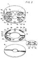
- Fig. 2 is a schematic, exploded perspective view illustrating the manner in which electrical connections are established between magnetic heads and a rotary transformer in the apparatus of Fig. 1;
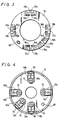
- Fig. 3 is a top plan view of a terminal plate shown in Fig. 2;
- Fig. 4 is a bottom plan view of a rotary drum member shown in Fig. 2;
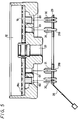
- Fig. 5 is an exploded axial sectional view of a stationary drum member and printed circuit board included in the head drum apparatus of Fig. 1;
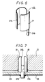
- Fig. 6 is an enlarged perspective view of a ground contact pin used in the rotary head drum apparatus shown in Fig. 5;
- Fig. 7 is a diagrammatic, fragmentary sectional view showing how the ground contact pin of Fig. 6 is fitted into an aperture of the stationary drum member; and
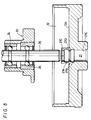
- Fig. 8 is an exploded axial sectional view illustrating the manner in which a support shaft is fitted into the stationary drum member in the rotary head drum apparatus according to the present invention.
- Referring to the drawings in detail and initially to Fig. 1 which shows an overall arrangement of an embodiment of a rotary head drum apparatus according to the present invention, it will be seen that such rotary head drum apparatus generally comprises a
rotary drum member 11 having at least onemagnetic head 10 mounted thereon, and astationary drum member 12 that is disposed coaxially below therotary drum member 11. Eachmagnetic head 10 is mounted at the radially outer end of arespective head base 13 which is secured to the lower surface of therotary drum member 11 by ascrew 14. Acontactor 16 is attached to aterminal plate 15 for eachmagnetic head 10 for electrically connecting the respectivemagnetic head 10 with arotor 18 of arotary transformer 17. Therotary transformer 17 is used to transmit signals between therotary drum member 11 and thestationary drum member 12. Therotor 18 of therotary transformer 17 is attached to therotary drum member 11 for rotation with the latter, while itsstator 19 is attached to thestationary drum member 12. Therotor 18 and thestator 19 are axially opposed to each other with a very small air gap therebetween. - The electrical connection between each
magnetic head 10 mounted on therotary drum member 11 and therotor 18 of therotary transformer 17 will now be further described in detail with reference to Fig. 2 (and, in particular, with reference to the enlarged, side view encircled by an elliptical solid line in Fig. 2) and to Fig. 3. As there shown, thecontactor 16 provided on theterminal plate 15 for eachmagnetic head 10 is formed of twoleaf springs springs respective contact portions head base 13 having the respectivemagnetic head 10 mounted on its tip end (Figs. 2 and 4), a signal is transmitted between themagnetic head 10 and therotor 18 of therotary transformer 17. Preferably, the contact surfaces ofsprings contact portions - As will be hereinafter described in detail, when the
rotary drum member 11 carrying at least onemagnetic head 10 is mounted on aboss 20, thehead 10 may be simultaneously electrically connected to therotor 18 of therotary transformer 17. For this purpose, theterminal plate 15 is adhesively bonded or otherwise attached to the upper surface of therotor 18 of therotary transformer 17, and lead wires (not shown) extend fromcoils 18a (Fig. 1) of therotor 18 and are soldered toterminals terminal plate 15 between each pair of thecontactor springs - As shown on Figs. 1 and 2, the
terminal plate 15 has an upwardly directedpositioning pin 15a extending therefrom and being engageable in apositioning aperture 11a provided in therotary drum member 11 for circumferentially positioning theterminal plate 15 in respect to therotary drum member 11. Such circumferential positioning of theterminal plate 15 relative to therotary drum member 11 ensures that, upon assembly of the rotary head drum apparatus, the pairs of contactor springs 16a and 16b which are angularly spaced apart around theterminal plate 15, as shown on Fig. 2 will be angularly aligned with the respective angularly spaced apart heads 10 on therotary head member 11, and thus will be engageable with the associatedcontact portions - As shown on Fig. 1, the
rotary drum member 11 with themagnetic heads 10 mounted thereon is assembled on theboss 20 and secured to the latter by means of ascrew 23. Theboss 20 is rotatably mounted by means ofball bearings shaft 26. The lower end portion of the supportingshaft 26 is axially press-fitted into abore 27 extending axially through the center of thestationary drum member 12. A flexible printedcircuit board 28 has aterminal plate 29 mounted on an end portion thereof for attachment to the underside of thestationary drum member 12, as shown on Fig. 1. Signal transmitting pins 30 and ground contact pins 31 for grounding thestationary drum member 12 are implanted in theterminal plate 29 and will be hereinafter further described in detail. - A motor 34 (Fig. 1) is located within the
rotary drum member 11 for effecting rotation of the latter about the supportingshaft 26 relative to thestationary drum member 12. More specifically, themotor 34 is shown to include astator yoke 35 which is secured to therotary drum member 11 by ascrew 36 and amagnet 37 adhesively bonded or otherwise secured to thestator yoke 35. A printedcircuit board 38 located above themagnet 37 is fixed by ascrew 40 to aboss 39 which is fixedly located on the upper end portion of the supportingshaft 26. The printedcircuit board 38 includes a coil (not shown) which is in operative opposing relation to themagnet 37. Aterminal plate 42 attached to an end portion of aflexible base plate 41 is also secured to theboss 39 by means of thescrew 40, and the previously mentioned coil formed on the printedcircuit board 38 receives the driving current for themotor 34 by way of suitable leads on theflexible base plate 41. - It will be understood that, when the
rotary drum member 11 secured to theboss 20 rotatably mounted on the supportingshaft 26 is assembled axially in respect to thestationary drum member 12 with therotary transformer 17 therebetween, the contactor springs 16a and 16b provided on theterminal plate 15 attached to the upper surface of therotor 18 come into resilient contact with therespective contact portions head base 13 and are made to flex for providing reliable electrical connections between themagnetic heads 10 and the respective coils of therotor 18. Therefore, the steps required in assembling the rotary head drum apparatus embodying this invention are substantially simplified in that the electrical connections between themagnetic heads 10 and therotor 18 of therotary transformer 17 are made simultaneously with the axial assembling together of the rotary andstationary drum members magnetic heads 10 and therotor 18 of thetransformer 17 can be provided in a very small or contained space. - Moreover, since the electrical connections between the
magnetic heads 10 and therotor 18 of therotary transformer 17 are not provided by a soldering process that has to be conducted near to the rotary head drum apparatus, there is no danger that flux or solder balls will undesirably enter the rotary head drum apparatus. Moreover, since thesprings contactors 16 are flexed to engage therespective contact portions magnetic heads 10 can be reliably and accurately mounted on therespective head bases 13 without the danger that such head bases will be warped or distorted by excessive forces applied thereto in achieving the necessary contacts. - Although the
contact portions bases 13 supporting themagnetic heads 10 and the respectiveresilient contactors 16 are provided on theterminal plate 15 positioned above therotor 18 of therotary transformer 17 in the illustrated embodiment of the invention, it will be apparent that the positions of thecontact portions resilient contactors 16 may be reversed. In other words, theresilient contactors 16 can depend from the undersides of the head bases 13 for resiliently engaging thecontact portions terminal plate 15. - Referring now to Figs. 5, 6 and 7, it will be seen that each
ground contact pin 31 is formed of a conductive metal sheet material and preferably includes a generally cylindrical body having diametrically opposed longitudinally directedslits slit 31A, as shown on Figs. 6 and 7, extends along the entire length of the cylindrical body while the opposing slit 31′A extends only along the upper portion of the cylindrical body which is radial resilient by reason of theslits lead portion 31B is directed downwardly from the lower end of the cylindrical body of thepin 31, preferably at the side of the latter having thepartial slit 31′A. Thelead portion 31B extends downwardly through theterminal plate 29 and the flexible printedcircuit board 28, as shown on Figs. 5 and 7, and is soldered to a respective portion of the printed circuit on theboard 28. The signal transmitting pins 30 directed upwardly from theterminal plate 29 and being similarly connected, as by solder, to the printed circuit on theboard 28, are engaged inrespective connectors 60 extending from the underside of thestator 19 in response to the positioning of theterminal plate 29 against the bottom surface of thestationary drum member 12. Simultaneously with the foregoing, the longitudinally slit cylindrical bodies of the ground contact pins 31 are fitted axially into correspondingapertures 61 formed in thestationary drum member 12. Thus, thestationary drum member 12 is connected to ground by way of thepins 31 suitably electrically connected with the printed circuit on theboard 28. The cylindrical bodies of thepins 31 are desirably normally dimensioned so that the axial insertion thereof into theapertures 61 is accompanied by radial contraction of the contact pins 31. Thus, the ground contact pins 31 are pressed against the surfaces of therespective apertures 61 by their resilient restoring forces for ensuring reliable electrical contact of thepins 31 with thestationary drum member 12 which is desirably formed of aluminum. - Since the soldering process for connecting the
pins board 28 is effected remote from thestationary drum member 12, establishing electrical connections by way of thepins 30 withrespective coils 19a of thestator 19 of therotary transformer 17, and the connection of thestationary drum member 12 to ground by way of thepins 31 can be effected without the danger of solder flux entering the stationary drum member. - Furthermore, since the
apertures 61 are formed in an end face of thestationary drum member 12 for receiving the ground contact pins 31 which are resilient or flexible in the radial direction, the stationary drum member can be conveniently and reliably connected to ground merely by the axial insertion of thepins 31 in therespective apertures 61, and without the need to employ screws for maintaining the engagement of thepins 31 in theapertures 61. By reason of the absence of such screws, the tracking accuracy of the magnetic head or heads can be ensured for avoiding disturbance of a video image to be reproduced by a VTR having the rotary head drum apparatus embodying this invention. - Referring now to Fig. 8, it will be seen that, in the illustrated rotary head drum apparatus embodying this invention, the
bore 27 extending axially through the center of thestationary drum member 12 is formed with two vertically spaced apart concave or undercut annuli 27A and 27B so as to define annular seating portions or lands 27C, 27D and 27E which are located axially above theconcave annulus 27A, intermediate theconcave annuli concave annulus 27B, respectively. By reason of theconcave annuli bore 27 is relieved, the supportingshaft 26, when being pressed axially downward into thebore 27, engages the surface of the bore only at the seating orland portions shaft 26 has a press fit within thebore 27 for suitably securing theshaft 26 relative to thestationary drum member 12, seizing or scoring of theshaft 26 or of the surface of thebore 27 is avoided during insertion of theshaft 26 into thebore 27. More specifically, as the supportingshaft 26 is urged axially downward into thebore 27, theshaft 26 initially only engages the surface of theland 27C. As the downward movement of theshaft 26 continues, the surface of the shaft comes into engagement with theland 27D while still engaging theuppermost land 27C. The axial dimensions of the first andsecond lands shaft 26 for moving the latter downwardly past thelands shaft 26 to the extent required for engagement with theland 27D as well as with theland 27C is referred to as a preliminary fitting operation and ensures that, as the lower end of theshaft 26 nears the lowermost seating portion orland 27E, theshaft 26 will be precisely in axial alignment with thebore 27 and not canted in respect to the latter. - When the lower end of the
shaft 26 reaches the upper edge of the seating portion orland 27E which has a relatively large axial dimension, further downward movement of theshaft 26 requires a gradual increase of the axial force applied to theshaft 26, for example, from 10 kg to about 100 kg. The maximum value of the axial force applied to theshaft 26 during such main fitting or inserting operation depends upon the axial dimension of theland 27E. In any case, after theshaft 26 has been axially inserted so as to fully engage theland 27E, for example, as in Fig. 1, the relatively large area of contact ofsuch land 27E with the surface of the supportingshaft 26 serves to ensure the secure mounting of the shaft in thestationary drum member 12. Further, since the preliminary fitting operation during which the surface of the supportingshaft 26 engages only the relatively small areas of thelands shaft 26, the accurate axial alignment of theshaft 26 with thebore 27 can be reliably maintained. Thereafter, during the main fitting operation in which a large axial force is applied to theshaft 26, the fact that theshaft 26 is not inclined or canted relative to thebore 27 ensures that the main fitting operation can be smoothly and accurately carried out. For example, the desired vertical position of theshaft 26, and hence of theheads 10 carried by thedrum member 12 supported by the shaft, can be achieved within a tolerance of only 2 »m. As distinguished from the foregoing, in the prior art in which the bore of the stationary drum member has a continuous surface so that the described preliminary fitting operation does not occur, the supporting shaft may be inclined or canted relative to the axis of the bore into which it is being press-fitted and high accuracy in the vertical positioning of the shaft cannot be realized. - It will be appreciated that, in the operation of the described rotary head drum apparatus embodying this invention, magnetic tape is suitably guided so as to be wrapped around the outer peripheral surfaces of the
rotary drum member 10 and thestationary drum member 12 which are coaxial with each other. When therotary drum member 11 is rotated by themotor 34, themagnetic heads 10 extending from thebases 13 mounted on therotary drum member 11 scan tracks extending obliquely across the magnetic tape for effecting helical scanning of the latter. In the recording mode, signals are supplied from stationary recording circuits through therotary transformer 17 to themagnetic heads 10 and are thereby recorded in the scanned tracks on the magnetic tape. Alternatively, in the reproducing mode, signals recorded in the oblique tracks on the magnetic tape are read out therefrom by the magnetic heads scanning such tracks and the reproduced signals are supplied through therotary transformer 17 to stationary reproducing circuits. - Having described a preferred embodiment of the invention with reference to the accompanying drawings, it is to be understood that the invention is not limited to that precise embodiment.
Claims (12)
- A rotary head drum apparatus in which at least one magnetic head (10) is attached to a rotary drum member (11) for rotation relative to a stationary structure (12), and a rotary transformer (17) is provided for transmitting electrical signals between said magnetic head (10) and said stationary structure (12) and includes a rotor (18) and a stator (19) fixed relative to said rotary drum member (11) and said stationary structure (12), respectively, and having respective coils (18a,19a); characterized in that it comprises means for connecting said magnetic head (10) to the coil of said rotor (18) of the rotary transformer (17) comprising :
resilient contactor means (16a,16b) mounted on one of said rotary drum member (11) and said rotor (18); and
contact portion means (13a,13b) on the other of said rotary drum member (11) and said rotor (18) for contact with said contactor means (16a,16b) and wherein said contactor means (16a,16b) is urged resiliently against said contact portion means (13a,13b) in response to assembling together of said rotary drum member (11) and said rotary transformer (17);
characterised in that said contactor elements (16a,16b) are substantially L-shaped and have free end portions directed toward each other. - The rotary head drum apparatus according to claim 1; characterized in that said contact portion means (13a,13b) have contact surfaces extending in a plane perpendicular to an axis of rotation of said rotary drum member (11), said contactor means (16a,16b) are engageable against said contact surfaces (13a,13b) and are resiliently flexible in directions parallel with said axis of rotation, and said assembling together of said rotary drum member (11) and said rotary transformer (17) is effected by displacement of said rotary drum member (11) in the direction of said axis of rotation relative to said stationary structure (12) for resiliently flexing said contactor means (16a, 16b) against said contact surfaces (13a,13b).
- The rotary head drum apparatus according to claim 2; characterized in that said contactor means (16a,16b) includes two contactor elements having portions which are resiliently flexible in said directions parallel with the axis of rotation.
- The rotary head drum apparatus according to claim 3; characterized in that said contactor means (16a,16b) further includes terminal portions (21a,21b) for connection by solder to a respective coil (18a) of said rotor (18).
- The rotary head drum apparatus according to claim 4; characterized in that said terminal portions (21a,21b) are positioned intermediate said contactor elements (16a,16b).
- The rotary head drum apparatus according to claim 1; characterized in that said stationary structure (12) includes a stationary drum member coaxial with said rotary drum member (11) and having a central bore (27) extending axially in said stationary drum member (12), a support shaft (26) inserted axially with a press fit in said bore (27), and bearing means (24,25) rotatably mounting said rotary drum member (11) on said support shaft (26) said bore (27) having annular relief means (27A,27B) therein for dividing the surface of said bore (27) into axially spaced lands (27C,27D,27E) so that, as said shaft (26) is inserted axially into said bore (27), said lands (27C,27D,27E) are successively engaged by the shaft surface.
- The rotor head drum apparatus according to claim 6; characterized in that said annular relief means includes two axially spaced concave annuli (27A,27B) axially dividing said surface of the bore (27) into two axially spaced, relatively narrow lands (27C,27D) initially engaged by said shaft surface for axially aligning the shaft (26) with the bore (27) as the shaft (26) is inserted in said bore (27) and a relatively wide land (27E) finally engaged by said shaft surface as insertion of the shaft (26) into said bore (27) is completed for securing said shaft (26) in said bore (27).
- The rotary head drum apparatus according to claim 6; characterized in that said stationary drum member (12) has an end face with an aperture (61) extending through said end face, and further comprising ground contact means (31) having a body portion which is radially resilient and frictionally engaged in said aperture for connecting said stationary drum member (12) to ground.
- The rotary head drum apparatus according to claim 1; characterized in that said stationary structure includes a stationary drum member (12) coaxial with said rotary drum member (11) and carrying a support shaft (26) on which the rotary drum member (11) is mounted so that outer peripheral surfaces of said rotary and stationary drum members form a guide surface for a recording tape to be scanned by said head (10), and said stationary drum (12) has an end face with an aperture (61) therein; and further comprising ground contact means (31) having a body portion which is radially resilient and frictionally engaged in said aperture (61) for connecting said stationary drum member (12) to ground.
- The rotary head drum apparatus according to claim 9; characterized in that said body portion (31) of the ground contact means is cylindrical and has longitudinal slits (31A,31′A).
- The rotary head drum apparatus according to claim 9; characterized in that it further comprises a printed circuit board (28) disposed against said end face and in which said ground contact means (31) are implanted.
- The rotary head drum apparatus according to claim 8; characterized in that said aperture (61) in said end face of said stationary drum member (12) is spaced radially from said support shaft (26).
Applications Claiming Priority (6)
| Application Number | Priority Date | Filing Date | Title |
|---|---|---|---|
| JP159943/88 | 1988-06-28 | ||
| JP63159944A JP2805706B2 (en) | 1988-06-28 | 1988-06-28 | Head drum device |
| JP63159942A JP2595665B2 (en) | 1988-06-28 | 1988-06-28 | Rotating head device |
| JP63159943A JP2565266B2 (en) | 1988-06-28 | 1988-06-28 | Fixed drum grounding device |
| JP159942/88 | 1988-06-28 | ||
| JP159944/88 | 1988-06-28 |
Publications (3)
| Publication Number | Publication Date |
|---|---|
| EP0349430A2 EP0349430A2 (en) | 1990-01-03 |
| EP0349430A3 EP0349430A3 (en) | 1992-02-26 |
| EP0349430B1 true EP0349430B1 (en) | 1995-05-17 |
Family
ID=27321599
Family Applications (1)
| Application Number | Title | Priority Date | Filing Date |
|---|---|---|---|
| EP89401858A Expired - Lifetime EP0349430B1 (en) | 1988-06-28 | 1989-06-28 | Rotary head drum apparatus |
Country Status (4)
| Country | Link |
|---|---|
| US (2) | US5010432A (en) |
| EP (1) | EP0349430B1 (en) |
| DE (1) | DE68922662T2 (en) |
| ES (1) | ES2072309T3 (en) |
Cited By (1)
| Publication number | Priority date | Publication date | Assignee | Title |
|---|---|---|---|---|
| US6408307B1 (en) | 1995-01-11 | 2002-06-18 | Civix-Ddi, Llc | System and methods for remotely accessing a selected group of items of interest from a database |
Families Citing this family (34)
| Publication number | Priority date | Publication date | Assignee | Title |
|---|---|---|---|---|
| US5010432A (en) * | 1988-06-28 | 1991-04-23 | Sony Corporation | Rotary head drum apparatus comprising resilient electrical connectors |
| US5483401A (en) * | 1990-08-08 | 1996-01-09 | Canon Kabushiki Kaisha | Rotary head drum having a connecting member for providing electrical conduction |
| JPH081775B2 (en) * | 1990-11-28 | 1996-01-10 | 三菱電機株式会社 | Electromagnetic contactor |
| DE4104264C2 (en) * | 1991-02-13 | 1996-09-26 | Broadcast Television Syst | Rotating scanner for a magnetic tape device |
| JPH04319501A (en) * | 1991-04-19 | 1992-11-10 | Hitachi Ltd | Rotary magnetic head device and rotary transformer used therein |
| JPH04351710A (en) * | 1991-05-30 | 1992-12-07 | Sony Corp | Rotary head drum device |
| FR2677792B1 (en) * | 1991-06-12 | 1993-09-24 | Schlumberger Ind Sa | DEVICE AND METHOD FOR RECORDING AND / OR READING INFORMATION ON A MAGNETIC TAPE. |
| US5579535A (en) * | 1991-07-01 | 1996-11-26 | Motorola, Inc. | Personal communication system providing supplemental information mode |
| JP3060623B2 (en) * | 1991-07-12 | 2000-07-10 | ソニー株式会社 | Rotary head drum assembly equipment |
| KR0178552B1 (en) * | 1992-11-25 | 1999-04-15 | 사또오 후미오 | Rotary magnetic head apparatus and a device for electrically connecting the same |
| DE4314423A1 (en) * | 1993-05-03 | 1994-11-10 | Philips Patentverwaltung | Magnetic tape device |
| US5442506A (en) * | 1993-05-31 | 1995-08-15 | Daewoo Electronics Co., Ltd. | Head drum ground system having a resiliently mounted conductive brush |
| US5311400A (en) * | 1993-06-16 | 1994-05-10 | Gec-Marconi Electronic Systems Corp. | Low profile header assembly for an encapsulated instrument |
| US5764442A (en) * | 1993-08-17 | 1998-06-09 | Kabushiki Kaisha Sankyo Seiko Seisakusho | Rotary head drum with shielding of heads and rotary transformers |
| JPH0757201A (en) * | 1993-08-19 | 1995-03-03 | Toshiba Corp | Rotary head device |
| KR950006824A (en) * | 1993-08-24 | 1995-03-21 | 배순훈 | Optical disk device |
| GB2282906B (en) | 1993-10-13 | 1996-11-06 | Dataquill Ltd | Data enty systems |
| KR950015299U (en) * | 1993-11-29 | 1995-06-17 | Full width eraser head connection structure of video cassette recorder | |
| US5515220A (en) * | 1993-12-30 | 1996-05-07 | Alioth; Henry L. | Multielement disk-shaped rotary magnetic media scanners for magnetic media player-recorders |
| US5646806A (en) * | 1994-02-09 | 1997-07-08 | Minnesota Mining And Manufacturing Company | Edge tensioning sloping tape guide for arcuately scanning tape drive |
| KR0115136Y1 (en) * | 1994-06-13 | 1998-04-18 | 강진구 | Head drum fixing structure |
| KR0151476B1 (en) * | 1995-04-29 | 1998-10-15 | 배순훈 | Headdrum assembly and the assembling method |
| KR19980017840A (en) * | 1996-08-31 | 1998-06-05 | 배순훈 | Head Base Fixing Structure of Head Drum Assembly |
| KR100215417B1 (en) * | 1997-03-26 | 1999-08-16 | 전주범 | Structure for setting head base in vcr |
| USD433407S (en) * | 1997-07-11 | 2000-11-07 | Sony Corporation | Drum for video tape recorder |
| KR20000003059A (en) * | 1998-06-25 | 2000-01-15 | 윤종용 | Head drum assembly of tape recorder |
| JP2003529177A (en) | 2000-03-27 | 2003-09-30 | コーニンクレッカ フィリップス エレクトロニクス エヌ ヴィ | Apparatus having disk-shaped support crimped to drive shaft |
| US7100265B2 (en) * | 2000-11-29 | 2006-09-05 | Athan Corporation | Method for aligning a drum assembly used in a video recording device |
| US6588120B2 (en) * | 2000-11-29 | 2003-07-08 | Athan Corporation | Method and apparatus for aligning a drum assembly used in a video recording device |
| KR100451555B1 (en) * | 2002-09-26 | 2004-10-08 | 삼성전자주식회사 | Connection structure of capstan motor for tape recorder |
| US7260884B2 (en) * | 2003-04-15 | 2007-08-28 | Athan Corporation | Method of manufacturing a drum assembly associated with video tape machine |
| JP2004342249A (en) * | 2003-05-16 | 2004-12-02 | Mitsumi Electric Co Ltd | Rotary head drum unit |
| US20080304185A1 (en) * | 2007-06-06 | 2008-12-11 | George Athanasiou | Drum assembly associated with video tape machine |
| JP7154379B2 (en) * | 2019-03-12 | 2022-10-17 | アルプスアルパイン株式会社 | Electromagnetic drive and operating device |
Family Cites Families (16)
| Publication number | Priority date | Publication date | Assignee | Title |
|---|---|---|---|---|
| NL7906478A (en) * | 1979-08-29 | 1981-03-03 | Philips Nv | DEVICE FOR THE MAGNETIC REGISTRATION AND READING OF SIGNALS OF LARGE BANDWIDTH. |
| JPS5788523A (en) * | 1980-11-25 | 1982-06-02 | Hitachi Ltd | Video head height adjusting mechanism for rotary magnetic recorder and reproducer |
| JPS5819729A (en) * | 1981-07-29 | 1983-02-04 | Hitachi Ltd | Magnetic head drum |
| JPS59223906A (en) * | 1983-06-03 | 1984-12-15 | Hitachi Ltd | Rotary magnetic head device |
| JPS6085715U (en) * | 1983-11-18 | 1985-06-13 | アルプス電気株式会社 | magnetic tape guide drum |
| JPS61222015A (en) * | 1985-03-27 | 1986-10-02 | Canon Inc | Magnetic head device |
| JPS61265720A (en) * | 1985-05-20 | 1986-11-25 | Matsushita Electric Ind Co Ltd | Rotary magnetic head device |
| AT382976B (en) * | 1985-07-15 | 1987-05-11 | Philips Nv | RECORDING AND / OR PLAYING DEVICE |
| JPS6236722A (en) * | 1985-08-12 | 1987-02-17 | Hitachi Ltd | Rotary magnetic head device |
| JPH0740339B2 (en) * | 1986-05-14 | 1995-05-01 | 株式会社日立製作所 | Magnetic recording / reproducing device |
| JPS6332704A (en) * | 1986-07-26 | 1988-02-12 | Sony Corp | Rotary magnetic head device |
| JPS6394405A (en) * | 1986-10-08 | 1988-04-25 | Toshiba Corp | Rotating magnetic head drum |
| JPH0629762Y2 (en) * | 1986-11-05 | 1994-08-10 | 株式会社日立製作所 | Rotating magnetic head unit |
| JPH01302501A (en) * | 1988-05-31 | 1989-12-06 | Canon Inc | Magnetic recording and reproducing device |
| US5010432A (en) * | 1988-06-28 | 1991-04-23 | Sony Corporation | Rotary head drum apparatus comprising resilient electrical connectors |
| JP2565266B2 (en) * | 1988-06-28 | 1996-12-18 | ソニー株式会社 | Fixed drum grounding device |
-
1989
- 1989-06-26 US US07/371,293 patent/US5010432A/en not_active Expired - Lifetime
- 1989-06-28 DE DE68922662T patent/DE68922662T2/en not_active Expired - Lifetime
- 1989-06-28 ES ES89401858T patent/ES2072309T3/en not_active Expired - Lifetime
- 1989-06-28 EP EP89401858A patent/EP0349430B1/en not_active Expired - Lifetime
-
1990
- 1990-11-13 US US07/612,415 patent/US5113298A/en not_active Expired - Lifetime
Non-Patent Citations (1)
| Title |
|---|
| PATENT ABSTRACTS OF JAPAN vol. 9, no. 97 (P-352)(1820), 26 April 1985; & JP - A - 59223906 (HITACHI SEISAKUSHO K.K.) 15.12.1984 * |
Cited By (2)
| Publication number | Priority date | Publication date | Assignee | Title |
|---|---|---|---|---|
| US6408307B1 (en) | 1995-01-11 | 2002-06-18 | Civix-Ddi, Llc | System and methods for remotely accessing a selected group of items of interest from a database |
| US6415291B2 (en) | 1995-01-11 | 2002-07-02 | Civix-Ddi, Llc | System and methods for remotely accessing a selected group of items of interest from a database |
Also Published As
| Publication number | Publication date |
|---|---|
| EP0349430A3 (en) | 1992-02-26 |
| DE68922662T2 (en) | 1995-10-05 |
| US5010432A (en) | 1991-04-23 |
| ES2072309T3 (en) | 1995-07-16 |
| US5113298A (en) | 1992-05-12 |
| DE68922662D1 (en) | 1995-06-22 |
| EP0349430A2 (en) | 1990-01-03 |
Similar Documents
| Publication | Publication Date | Title |
|---|---|---|
| EP0349430B1 (en) | Rotary head drum apparatus | |
| US5781380A (en) | Swing-type actuator assembly having internal conductors | |
| US5321569A (en) | Rotary magnetic head drum assembly | |
| US4823218A (en) | Balance compensated rotary magnetic head device | |
| US5325248A (en) | Rotary head assembly | |
| KR0178552B1 (en) | Rotary magnetic head apparatus and a device for electrically connecting the same | |
| US6875026B2 (en) | Hard disk drive with connectors that simplify assembly | |
| US5808841A (en) | Recording and/or reproducing apparatus having rotary drum unit | |
| JPH029012A (en) | Rotary head device | |
| JP2574886B2 (en) | Rotary drum device | |
| US5682283A (en) | Rotary head apparatus having short distance between magnetic heads and rotary transformer | |
| US6028747A (en) | Head drum assembly having a member locating and fixing video heads on an upper drum | |
| KR0178802B1 (en) | Rotary cylinder power feeding apparatus | |
| JP2565266B2 (en) | Fixed drum grounding device | |
| JPH06195605A (en) | Rotary head drum device | |
| US20030036296A1 (en) | Method for attaching a connector to a printed circuit board of a disc drive | |
| JPH0722730Y2 (en) | Rotating magnetic recording / reproducing device | |
| JP2814508B2 (en) | Rotating head device | |
| JP2595665C (en) | ||
| JPH029013A (en) | Head drum device | |
| JPS6236717A (en) | Rotary magnetic head device | |
| JPH11149601A (en) | Rotary transformer and rotary head drum device using it | |
| JP3175488B2 (en) | Rotating head cylinder device | |
| JPH07336004A (en) | Connecting structure of circuit boards | |
| JP2002042316A (en) | Circuit board attaching structure and rotary drum device |
Legal Events
| Date | Code | Title | Description |
|---|---|---|---|
| PUAI | Public reference made under article 153(3) epc to a published international application that has entered the european phase |
Free format text: ORIGINAL CODE: 0009012 |
|
| AK | Designated contracting states |
Kind code of ref document: A2 Designated state(s): DE ES FR GB NL |
|
| PUAL | Search report despatched |
Free format text: ORIGINAL CODE: 0009013 |
|
| AK | Designated contracting states |
Kind code of ref document: A3 Designated state(s): DE ES FR GB NL |
|
| 17P | Request for examination filed |
Effective date: 19920812 |
|
| 17Q | First examination report despatched |
Effective date: 19930504 |
|
| GRAA | (expected) grant |
Free format text: ORIGINAL CODE: 0009210 |
|
| AK | Designated contracting states |
Kind code of ref document: B1 Designated state(s): DE ES FR GB NL |
|
| REF | Corresponds to: |
Ref document number: 68922662 Country of ref document: DE Date of ref document: 19950622 |
|
| REG | Reference to a national code |
Ref country code: ES Ref legal event code: FG2A Ref document number: 2072309 Country of ref document: ES Kind code of ref document: T3 |
|
| ET | Fr: translation filed | ||
| PLBE | No opposition filed within time limit |
Free format text: ORIGINAL CODE: 0009261 |
|
| STAA | Information on the status of an ep patent application or granted ep patent |
Free format text: STATUS: NO OPPOSITION FILED WITHIN TIME LIMIT |
|
| 26N | No opposition filed | ||
| REG | Reference to a national code |
Ref country code: GB Ref legal event code: IF02 |
|
| PGFP | Annual fee paid to national office [announced via postgrant information from national office to epo] |
Ref country code: DE Payment date: 20080703 Year of fee payment: 20 Ref country code: ES Payment date: 20080717 Year of fee payment: 20 Ref country code: NL Payment date: 20080603 Year of fee payment: 20 |
|
| PGFP | Annual fee paid to national office [announced via postgrant information from national office to epo] |
Ref country code: FR Payment date: 20080617 Year of fee payment: 20 |
|
| PGFP | Annual fee paid to national office [announced via postgrant information from national office to epo] |
Ref country code: GB Payment date: 20080702 Year of fee payment: 20 |
|
| REG | Reference to a national code |
Ref country code: GB Ref legal event code: PE20 Expiry date: 20090627 |
|
| PG25 | Lapsed in a contracting state [announced via postgrant information from national office to epo] |
Ref country code: NL Free format text: LAPSE BECAUSE OF EXPIRATION OF PROTECTION Effective date: 20090628 |
|
| REG | Reference to a national code |
Ref country code: ES Ref legal event code: FD2A Effective date: 20090629 |
|
| NLV7 | Nl: ceased due to reaching the maximum lifetime of a patent |
Effective date: 20090628 |
|
| PG25 | Lapsed in a contracting state [announced via postgrant information from national office to epo] |
Ref country code: ES Free format text: LAPSE BECAUSE OF EXPIRATION OF PROTECTION Effective date: 20090629 |
|
| PG25 | Lapsed in a contracting state [announced via postgrant information from national office to epo] |
Ref country code: GB Free format text: LAPSE BECAUSE OF EXPIRATION OF PROTECTION Effective date: 20090627 |