EP0350336A2 - Optical memory system - Google Patents
Optical memory system Download PDFInfo
- Publication number
- EP0350336A2 EP0350336A2 EP89306986A EP89306986A EP0350336A2 EP 0350336 A2 EP0350336 A2 EP 0350336A2 EP 89306986 A EP89306986 A EP 89306986A EP 89306986 A EP89306986 A EP 89306986A EP 0350336 A2 EP0350336 A2 EP 0350336A2
- Authority
- EP
- European Patent Office
- Prior art keywords
- light beams
- sections
- light
- guide grooves
- optical memory
- Prior art date
- Legal status (The legal status is an assumption and is not a legal conclusion. Google has not performed a legal analysis and makes no representation as to the accuracy of the status listed.)
- Granted
Links
Images


Classifications
-
- G—PHYSICS
- G11—INFORMATION STORAGE
- G11B—INFORMATION STORAGE BASED ON RELATIVE MOVEMENT BETWEEN RECORD CARRIER AND TRANSDUCER
- G11B11/00—Recording on or reproducing from the same record carrier wherein for these two operations the methods are covered by different main groups of groups G11B3/00 - G11B7/00 or by different subgroups of group G11B9/00; Record carriers therefor
- G11B11/10—Recording on or reproducing from the same record carrier wherein for these two operations the methods are covered by different main groups of groups G11B3/00 - G11B7/00 or by different subgroups of group G11B9/00; Record carriers therefor using recording by magnetic means or other means for magnetisation or demagnetisation of a record carrier, e.g. light induced spin magnetisation; Demagnetisation by thermal or stress means in the presence or not of an orienting magnetic field
- G11B11/105—Recording on or reproducing from the same record carrier wherein for these two operations the methods are covered by different main groups of groups G11B3/00 - G11B7/00 or by different subgroups of group G11B9/00; Record carriers therefor using recording by magnetic means or other means for magnetisation or demagnetisation of a record carrier, e.g. light induced spin magnetisation; Demagnetisation by thermal or stress means in the presence or not of an orienting magnetic field using a beam of light or a magnetic field for recording by change of magnetisation and a beam of light for reproducing, i.e. magneto-optical, e.g. light-induced thermomagnetic recording, spin magnetisation recording, Kerr or Faraday effect reproducing
- G11B11/1055—Disposition or mounting of transducers relative to record carriers
- G11B11/10556—Disposition or mounting of transducers relative to record carriers with provision for moving or switching or masking the transducers in or out of their operative position
- G11B11/10563—Access of indexed parts
-
- G—PHYSICS
- G11—INFORMATION STORAGE
- G11B—INFORMATION STORAGE BASED ON RELATIVE MOVEMENT BETWEEN RECORD CARRIER AND TRANSDUCER
- G11B7/00—Recording or reproducing by optical means, e.g. recording using a thermal beam of optical radiation by modifying optical properties or the physical structure, reproducing using an optical beam at lower power by sensing optical properties; Record carriers therefor
- G11B7/002—Recording, reproducing or erasing systems characterised by the shape or form of the carrier
- G11B7/0033—Recording, reproducing or erasing systems characterised by the shape or form of the carrier with cards or other card-like flat carriers, e.g. flat sheets of optical film
-
- G—PHYSICS
- G11—INFORMATION STORAGE
- G11B—INFORMATION STORAGE BASED ON RELATIVE MOVEMENT BETWEEN RECORD CARRIER AND TRANSDUCER
- G11B7/00—Recording or reproducing by optical means, e.g. recording using a thermal beam of optical radiation by modifying optical properties or the physical structure, reproducing using an optical beam at lower power by sensing optical properties; Record carriers therefor
- G11B7/08—Disposition or mounting of heads or light sources relatively to record carriers
- G11B7/085—Disposition or mounting of heads or light sources relatively to record carriers with provision for moving the light beam into, or out of, its operative position or across tracks, otherwise than during the transducing operation, e.g. for adjustment or preliminary positioning or track change or selection
-
- G—PHYSICS
- G11—INFORMATION STORAGE
- G11B—INFORMATION STORAGE BASED ON RELATIVE MOVEMENT BETWEEN RECORD CARRIER AND TRANSDUCER
- G11B7/00—Recording or reproducing by optical means, e.g. recording using a thermal beam of optical radiation by modifying optical properties or the physical structure, reproducing using an optical beam at lower power by sensing optical properties; Record carriers therefor
- G11B7/12—Heads, e.g. forming of the optical beam spot or modulation of the optical beam
- G11B7/14—Heads, e.g. forming of the optical beam spot or modulation of the optical beam specially adapted to record on, or to reproduce from, more than one track simultaneously
Definitions
- the present invention relates to an optical memory system capable of performing data recording and reproduction by projecting a light beam onto an optical recording medium in the form of a disk, a card or the like.
- an optical memory system such as a magneto-optical memory system capable of recording data in a magneto-optical recording medium such as a magneto-optical disk, magneto-optical card etc., and reproducing data therefrom.
- the magneto-optical recording medium comprises a disk-shaped or card-shaped substrate made of a plastic or glass etc. and a magnetic film made of Gd, Te, Fe, Co, or the like formed on the back face of the substrate, and the direction of magnetisation of the magnetic film changes according to an external magnetic field which exerts an influence upon the magnetic film, when the temperature rises to Curie point or higher.
- a light beam whose intensity varies in accordance with data to be recorded is converged by an objective lens 13 or objective lens 18 so as to have a diameter of approximately 1 ⁇ m and is projected onto the magneto-optical disk 11 or the magneto-optical card 16.
- the temperature locally rises in the area irradiated by the light beam on the magnetic film of the magneto-optical disk 11 or the magneto-optical card 16 and when this temperature increases higher than Curie point, the direction of magnetisation of the magnetic film is inverted due to the effect of the external magnetic field generated by the magnet 12 or the magnet 17.
- Data recording can be performed by the above inversion of the magnetising direction of the magnetic film of the magneto-optical disk 11.
- a light beam which is linearly polarised and has such intensity that the temperature at the magnetic film does not rise higher than Curie point is projected onto the magneto-optical disk 11, and the area where data has been recorded is traced.
- the polarisation plane of reflected light from the magneto-optical disk 11 is inclined in compliance with the magnetising direction of the magnetic film at the area irradiated by the light beam due to magneto-optical effects such as Faraday effect and Kerr effect.
- the incline of the polarisation plane of the reflected light is converted into an electric signal by a photo-detector by way of an analyzer, thereby reproducing recorded data.
- the magneto-optical disk 11 and the magneto-optical card 16 are respectively provided with guide grooves 11a and guide grooves 16a formed in a direction parallel to the relative moving direction of the light beam and the magneto-optical disk 11 or the magneto-optical card 16.
- the intensity of the reflected light is decreased owing to the effect of diffraction or the like.
- This decrease in the intensity of the reflected light is converted into an electric signal and detected separately from signals to be obtained by the aforementioned magneto-optical effects by means of the photo-detector, thereby judging whether the irradiating position of the light beam on the magnetooptical disk 11 is appropriate or not.
- the irradiating position of the light beam is controlled whereby decentering and incline caused by installment of the magneto-optical disk 11 on a rotation axis or a slide stand can be cancelled.
- ID section 11b is disposed at a part of each guide groove 11a and an ID section 16b at a part of each guide groove 16a in order to identify on which groove the light beam is projected.
- Each ID section 11b has pits and when the light beam is projected on the ID sections 11b, the intensity of the reflected light changes due to diffraction or the like which occurs in accordance with the pit pattern. By detecting the change in the reflected light intensity and reproducing an ID signal, it can be identified on which guide groove 11a the light beam is projected.
- access operation is performed by moving the light beam in a direction perpendicular to the direction that the guide grooves 11a extend. In this case, an ID signal cannot be reproduced during the movement of the light beam, so that the travelling distance of the light beam to the desired guide groove 11a is estimated and coarse access operation is carried out by moving the light beam for the estimated distance.
- the light beam is shifted in a nearest guide groove 11a where an ID signal is reproduced thereby judging whether the guide groove 11a on which the light beam is projected is the desired guide groove or not. Then, the light beam is gradually moved and the above judging operation is repeated until the ID signal at the desired guide groove 11a is reproduced whereby the light beam can be projected on the desired guide groove 11a.
- the pitches of the guide grooves 11a and 16a are of the order of ⁇ m, whereas it is quite difficult to increase the mechanical accuracy of the system for moving the light beam to the same level as the above.
- reflected light from the magneto-optical disk is guided into a photo-detector 22 via a half mirror 21 and converted into an electric signal.
- the electric signal thus obtained is converted into a binary signal with a threshold voltage Vt thereby obtaining a pulse signal.
- a so-called track count method in which the number of pulses in a pulse signal is counted by a digital counter (not shown), the number of guide grooves 11a through which the light beam has passed, i.e., the moving amount of the light beam can be obtained.
- the rotation or slicing of the magneto-optical disk 11 or the magneto-optical card 16 is continuously carried out during access operation for projecting the light beam on a desired guide groove 11a, 16a. Therefore, the light beam sometimes obliquely crosses the guide grooves 11a, 16a passing through the ID sections 11b, 16b.
- the number of pulses in the pulse signal from the comparator 23 is included in the number of guide grooves 11a through which the light beam actually has passed. Consequently, the moving amount of the light beam cannot be precisely obtained, and this results in low accuracy of the coarse access operation.
- An object of the present invention is to provide an optical memory system wherein the number of guide grooves through which a light beam has actually passed can be counted even in the course of access operation for moving the light beam in a direction perpendicular to guide grooves 11a, by projecting a plurality of light beams on a recording medium and obtaining the reflected light or transmitted light of each light beam projected thereon.
- Another object of the present invention is to provide an optical memory system wherein the number of light beams projected on ID sections at the same time is limited to less than half of the total number of light beams projected on the recording medium whereby the majority of the light beams projected on the recording medium are not projected on the ID sections even when the light beams are moved in a direction perpendicular to the guide grooves.
- Still another object of the present invention is to provide an optical memory system wherein pulse signals generated by the effect of the ID sections are eliminated from pulse signals generated according to the reflected lights or transmitted lights of a plurality of light beams projected on the recording medium so that a pulse signal corresponding to the guide grooves through which the respective light beams have actually passed is taken out thereby obtaining the accurate moving amount of the desired light beam and improving the accuracy of the access operation.
- an optical memory system comprises: light beam generating means for generating a plurality of light beams; a recording medium comprising a plurality of guide grooves for guiding each of the light beams, and ID sections utilised for identifying a guide groove on which each of the light beams is projected; a plurality of photo-detectors for detecting the intensity of the reflected light or transmitted light of each of the light beams projected on the recording medium; a plurality of comparators for converting a signal released from each of the photo-detectors into a binary signal; a majority logic circuit for issuing a signal whose level is equivalent to the levels of the signals released from the majority of the comparators; and moving amount detecting means for detecting the moving amount of the light beams by counting the number of pulses in the pulse signal released from the majority logic circuit when the light beams move in a direction perpendicular to the guide grooves; said optical memory system being designed such that at least either the plurality of light beams or
- the above recording medium may be made of a plastic, glass, or other material in the form of a disk or a card, and may include a magnetic film comprising Cd, Te, Fe, Co, or the like formed on the back face thereof, the magnetising direction of the magnetic film changing in accordance with an external magnetic field which exerts an influence on the magnetic film.
- the above majority logic circuit may comprise logical elements such as an AND gate and OR gate, and the above moving amount detecting means may comprise a digital counter.
- the above recording medium may be arranged to have three adjacent ID sections placed so that at least two ID sections are not perfectly overlapped in a parallel direction to the guide grooves.
- the above recording medium may be arranged such that while the ID sections are aligned in a direction perpendicular to the guide grooves, a plurality of light beams are projected at intervals longer than the length of the ID section.
- the above light beam generating means may comprise a diffraction grating which diffracts a light beam from the light beam source into a zero-order light and two first-order lights.
- the respective numbers of light beams, photo-detectors, and comparators are not limited to three, but may correspond to the number of pulse signals with which a majority decision by the majority logic circuit can be performed.
- FIG. 1 to 4 one embodiment of an optical memory system for recording data in a magneto-optical disk and reproducing therefrom according to the present invention will be explained hereinbelow.
- An optical memory system 31 is provided with light beam generating means 32 comprising a light beam source 33 such as a laser light source etc. and a diffraction grating 34 as shown in Fig. 1.
- a light emitted from the light beam source 33 is diffracted by the diffraction grating 34 into one zero-order light and two first-order lights, thereby generating three light beams 37 to 39.
- a half mirror 35 and an objective lens 36 are provided under the light beam generating means 32.
- the objective lens 36 is designed to respectively converge the three light beams 37 to 39 generated by the light beam generating means 32 to project on a recording medium, i.e., a magneto-optical disk 41.
- the magneto-optical disk 41 comprises a substrate made of, for example, a plastic, glass, or other material in the form of a disk, and the back face of the substrate is coated with a magnetic film made of Gd, Te, Fe, Co or the like, of which magnetising direction changes according to the effect of an external magnetic field which exerts an influence on the magnetic film, when the temperature rises to Curie point or higher.
- This magneto-optical disk 41 is rotatively driven by actuating means (not shown).
- the magneto-optical disk 41 is also provided with concentric circular guide grooves 41a for guiding the light beams 37 to 39.
- the light beams 37 to 39 generated by the light beam generating means 32 are projected on the adjacent guide grooves 41a.
- the reflected lights of the three light beams 37 to 39 which have been projected on the magneto-optical disk 41 are respectively diverted by the half mirror 35 and guided into photo-detectors 51 to 53 for detecting the intensity of each reflected light, these photo-detectors 51 to 53 being disposed at a side of the half mirror 35.
- the photo-detectors 51 to 53 are respectively connected to comparators 54 to 56 each of which compares the levels of a signal released from the respective photo-detectors 51 to 53 with a predetermined reference voltage Vt thereby generating a binary signal.
- the comparators 54 to 56 are connected to a majority logic circuit 57 which has three AND circuits 57a and one OR circuit 57b.
- the majority logic circuit 57 generates a signal whose level is equivalent to the levels of signals released from two or more comparators out of the three comparators 54 to 56.
- the majority logic circuit 57 is connected to moving amount detecting means 58 which counts the number of pulses in a pulse signal released from the majority logic circuit 57 when the light beams 37 to 39 moves in a direction perpendicular to the guide grooves 41a in the magneto-optical disk 11, thereby detecting the moving amount of the light beams 37 to 39.
- This moving amount detecting means 58 comprises a digital counter or the like.
- Each of the guide grooves 41a in the magneto-optical disk 41 are provided with ID sections 41b as shown in Fig. 2.
- the ID sections 41b respectively have a pit pattern and are utilised for identifying guide grooves 41a on which the light beams 37 to 39 are projected.
- Three adjacent ID sections 41b are so placed, as shown in Fig. 2, that at least two ID sections are not perfectly overlapped in a parallel direction to the guide grooves. Therefore, when the light beam 37 is projected on the ID section 41b for instance, the other two light beams 38 and 39 are not projected on the ID sections 41b.
- the projecting positions of the light beams 37 to 39 on the magneto-optical disk 41 move in the direction of the arrow A and the light beams 37, 38 and 39 initiate to enter the ID sections 41b respectively in this order.
- the photo-detectors 51 to 53 subsequently release signals according to the respective pit patterns of the ID sections 41b, i.e., ID signals, and the comparators 54 to 56 release pulse signals according to the respective ID signals above mentioned.
- These pulse signals are deemed to be signals indicating guide grooves 41a on which the light beams 37 to 39 are respectively projected.
- the intensity of the corresponding reflected lights is decreased due to the effect of diffraction or the like at each time when one of the light beams 37 to 39 is projected on the vicinity of an edge portion of the ID sections 41b in the guide groove 41a. Therefore, one of the comparators 54 to 56 issues a low level signal whenever one of the light beams 37 to 39 passes through the vicinity of an edge portion of the ID section 41b in the guide groove 41a.
- the intensity of the respective reflected lights is decreased due to the effect of diffraction or the like generated in accordance with the pit patterns in the ID sections 41b, and accordingly the comparators 54 to 56 issue pulse signal sequences 61 according to the ID signals etc.
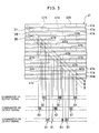
- the ID sections 41b are so arranged that at least more than half of the ID sections 41b are not perfectly overlapped in a parallel direction to the guide grooves 41a as shown in Fig. 3, and therefore when one of the light beams 37 to 39 is projected on the ID section 41b, the other two light beams are not projected on the ID sections 41b.
- two or more comparators do not issue pulse signal sequences 61 corresponding to the ID signals etc. at the same time.
- the signals released from the comparators 54 to 56 are entered in the majority logic circuit 57 and then the majority logic circuit 57 issues a signal after eliminating the pulse signal corresponding to the ID signals etc.
- the majority logic circuit 57 issues a signal having a level equivalent to the levels of signals released from two or more comparators out of the three comparators 54 to 56. Accordingly, the number of pulses in a pulse signal issued from the majority logic circuit 57 is coincident with the number of guide grooves 41a through which the respective light beams 37 to 39 have actually passed.
- the accurate moving amount of the light beams 37 to 39 can be obtained without the influence of the ID signals etc. by means of counting the number of pulses in the pulse signal from the majority logic circuit 57 by the moving amount detecting means 58.
- the light beams 37 to 39 are projected so that at least two light beams are not perfectly overlapped in a parallel direction to the guide grooves 41a, and the light beams 37 to 39 are projected at intervals longer than the length of the ID section 41b.
- the majority logic circuit 57 is not limited to the one having the AND circuits 57a and the OR circuit 57b as earlier mentioned.
- an optical memory system comprises: light beam generating means for generating a plurality of light beams; a recording medium comprising a plurality of guide grooves for guiding each of the light beams, and ID sections utilised for identifying a guide groove on which each of the light beams is projected; a plurality of photo-detectors for detecting the intensity of the reflected light or transmitted light of each of light beams projected on the recording medium; a plurality of comparators for converting a signal released from each of the photo-detectors into a binary signal; a majority logic circuit for issuing a signal whose level is equivalent to the levels of the signals released from the majority of the comparators; and moving amount detecting means for detecting the moving amount of the light beams by counting the number of pulses in the pulse signal released from the majority logic circuit when the light beams move in a direction perpendicular to the guide grooves; said optical memory system being designed such that at least either the plurality of light beams or the plurality of ID sections of
- the number of pulses in the pulse signal released from the majority logic circuit when the light beams move in a direction perpendicular to the guide grooves is not influenced by ID signals etc. and is coincident with the number of guide grooves through which the respective light beams have passed. Accordingly, the accurate moving amount of the light beams can be obtained resulting in high accuracy in access operation.
- the above recording medium may be made of a plastic, glass, or other material in the form of a disk or card, and may be designed to include a magnetic film comprising Cd, Te, Fe, Co, or the like formed on the back face thereof, and the magnetising direction of the magnetic film changing in accordance with an external magnetic field which exerts an influence upon the magnetic film.
- the magnetising direction of the magnetic film is locally inverted due to the effect of an external magnetic field.
- the above majority logic circuit may comprise logical elements such as an AND gate and OR gate, and the above moving amount detecting means may comprise a digital counter. This permits only the number of pulses corresponding to the number of guide grooves through which the respective light beams have actually passed to be obtained.
- the above recording medium may be arranged to have three adjacent ID sections placed such that at least two ID sections are not perfectly overlapped in a parallel direction to the guide grooves. This permits the number of light beams projected on the ID sections at the same time to be less than half of the total number of light beams projected on the recording medium.
- the number of light beams projected on the ID sections at the same time can be limited to less than half of the total number of light beams by such an arrangement that while the ID sections are aligned in a direction perpendicular to the guide grooves, the light beams are projected at intervals longer than the length of the ID section in such a manner that at least more than half of the light beams do not perfectly overlap one another in a parallel direction to the guide grooves.
- the above light beam generating means may comprise a diffraction grating which diffracts the light beam from the light beam source into a zero-order light and two first-order lights. This permits generation of three light beams from one light beam source.
- the respective numbers of light beams, photo- detectors and comparators are not limited to three but may correspond to the number of pulse signals with which a majority decision by the majority logic circuit can be performed.
Abstract
Description
- The present invention relates to an optical memory system capable of performing data recording and reproduction by projecting a light beam onto an optical recording medium in the form of a disk, a card or the like.
- There has been recently used for recording and reproducing a great amount of data, an optical memory system such as a magneto-optical memory system capable of recording data in a magneto-optical recording medium such as a magneto-optical disk, magneto-optical card etc., and reproducing data therefrom.
- The magneto-optical recording medium comprises a disk-shaped or card-shaped substrate made of a plastic or glass etc. and a magnetic film made of Gd, Te, Fe, Co, or the like formed on the back face of the substrate, and the direction of magnetisation of the magnetic film changes according to an external magnetic field which exerts an influence upon the magnetic film, when the temperature rises to Curie point or higher.
- In data recording operation using such a magneto-optical memory system, while a magneto-
optical disk 11 or a magneto-optical card 16 each having a magnetic film whose magnetising direction is prefixed in a desired uniform direction is rotated or slided, the effect of the external magnetic field generated by amagnet 12 ormagnet 17 is applied thereto in the opposite direction to the magnetising direction of the magnetic film, as shown in Figs. 6 and 7. - At the same time, a light beam whose intensity varies in accordance with data to be recorded is converged by an
objective lens 13 orobjective lens 18 so as to have a diameter of approximately 1 µm and is projected onto the magneto-optical disk 11 or the magneto-optical card 16. - In the case where the light beam has high intensity, the temperature locally rises in the area irradiated by the light beam on the magnetic film of the magneto-
optical disk 11 or the magneto-optical card 16 and when this temperature increases higher than Curie point, the direction of magnetisation of the magnetic film is inverted due to the effect of the external magnetic field generated by themagnet 12 or themagnet 17. Data recording can be performed by the above inversion of the magnetising direction of the magnetic film of the magneto-optical disk 11. - On the other hand, when reproducing data from the magneto-
optical disk 11, a light beam which is linearly polarised and has such intensity that the temperature at the magnetic film does not rise higher than Curie point is projected onto the magneto-optical disk 11, and the area where data has been recorded is traced. The polarisation plane of reflected light from the magneto-optical disk 11 is inclined in compliance with the magnetising direction of the magnetic film at the area irradiated by the light beam due to magneto-optical effects such as Faraday effect and Kerr effect. The incline of the polarisation plane of the reflected light is converted into an electric signal by a photo-detector by way of an analyzer, thereby reproducing recorded data. - When performing data recording or data reproduction as described above, it is required that the light beam is projected onto an appropriate position of the magneto-
optical disk 11. Therefore, as shown in Figs. 8 and 9, the magneto-optical disk 11 and the magneto-optical card 16 are respectively provided withguide grooves 11a andguide grooves 16a formed in a direction parallel to the relative moving direction of the light beam and the magneto-optical disk 11 or the magneto-optical card 16. - More specifically, when the light beam is projected in the vicinity of an edge portion of the
guide grooves 11a, the intensity of the reflected light is decreased owing to the effect of diffraction or the like. This decrease in the intensity of the reflected light is converted into an electric signal and detected separately from signals to be obtained by the aforementioned magneto-optical effects by means of the photo-detector, thereby judging whether the irradiating position of the light beam on themagnetooptical disk 11 is appropriate or not. Thereafter, on the basis of the signal thus detected, the irradiating position of the light beam is controlled whereby decentering and incline caused by installment of the magneto-optical disk 11 on a rotation axis or a slide stand can be cancelled. - As shown in Figs. 10 and 11, and
ID section 11b is disposed at a part of eachguide groove 11a and anID section 16b at a part of eachguide groove 16a in order to identify on which groove the light beam is projected. EachID section 11b has pits and when the light beam is projected on theID sections 11b, the intensity of the reflected light changes due to diffraction or the like which occurs in accordance with the pit pattern. By detecting the change in the reflected light intensity and reproducing an ID signal, it can be identified on whichguide groove 11a the light beam is projected. To project the light beam on a desiredguide groove 11a, access operation is performed by moving the light beam in a direction perpendicular to the direction that theguide grooves 11a extend. In this case, an ID signal cannot be reproduced during the movement of the light beam, so that the travelling distance of the light beam to the desiredguide groove 11a is estimated and coarse access operation is carried out by moving the light beam for the estimated distance. - Thereafter, the light beam is shifted in a
nearest guide groove 11a where an ID signal is reproduced thereby judging whether the guide groove 11a on which the light beam is projected is the desired guide groove or not. Then, the light beam is gradually moved and the above judging operation is repeated until the ID signal at the desiredguide groove 11a is reproduced whereby the light beam can be projected on the desiredguide groove 11a. - In the foregoing coarse access operation, the pitches of the
guide grooves - In order to overcome such a problem, the following arrangement has been conventionally proposed as shown in Fig. 12. That is, reflected light from the magneto-optical disk is guided into a photo-
detector 22 via ahalf mirror 21 and converted into an electric signal. The electric signal thus obtained is converted into a binary signal with a threshold voltage Vt thereby obtaining a pulse signal. By using a so-called track count method in which the number of pulses in a pulse signal is counted by a digital counter (not shown), the number of guide grooves 11a through which the light beam has passed, i.e., the moving amount of the light beam can be obtained. Generally, the rotation or slicing of the magneto-optical disk 11 or the magneto-optical card 16 is continuously carried out during access operation for projecting the light beam on a desiredguide groove guide grooves ID sections - In this case, there exists in an output signal from the photo-
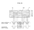
detector 22, an ID signal or the like based on the pit pattern formed in theID section 11b as shown in Fig. 13, and therefore, the number of pulses in the pulse signal generated by acomparator 23 is not coincident with the number ofguide grooves 11a through which alight beam 14 has actually passed. - In the conventional optical memory system as above described, the number of pulses in the pulse signal from the
comparator 23 is included in the number ofguide grooves 11a through which the light beam actually has passed. Consequently, the moving amount of the light beam cannot be precisely obtained, and this results in low accuracy of the coarse access operation. - An object of the present invention is to provide an optical memory system wherein the number of guide grooves through which a light beam has actually passed can be counted even in the course of access operation for moving the light beam in a direction perpendicular to guide
grooves 11a, by projecting a plurality of light beams on a recording medium and obtaining the reflected light or transmitted light of each light beam projected thereon. - Another object of the present invention is to provide an optical memory system wherein the number of light beams projected on ID sections at the same time is limited to less than half of the total number of light beams projected on the recording medium whereby the majority of the light beams projected on the recording medium are not projected on the ID sections even when the light beams are moved in a direction perpendicular to the guide grooves.
- Still another object of the present invention is to provide an optical memory system wherein pulse signals generated by the effect of the ID sections are eliminated from pulse signals generated according to the reflected lights or transmitted lights of a plurality of light beams projected on the recording medium so that a pulse signal corresponding to the guide grooves through which the respective light beams have actually passed is taken out thereby obtaining the accurate moving amount of the desired light beam and improving the accuracy of the access operation.
- In order to achieve the foregoing objects, an optical memory system according to the present invention comprises:
light beam generating means for generating a plurality of light beams;
a recording medium comprising a plurality of guide grooves for guiding each of the light beams, and ID sections utilised for identifying a guide groove on which each of the light beams is projected;
a plurality of photo-detectors for detecting the intensity of the reflected light or transmitted light of each of the light beams projected on the recording medium;
a plurality of comparators for converting a signal released from each of the photo-detectors into a binary signal;
a majority logic circuit for issuing a signal whose level is equivalent to the levels of the signals released from the majority of the comparators; and
moving amount detecting means for detecting the moving amount of the light beams by counting the number of pulses in the pulse signal released from the majority logic circuit when the light beams move in a direction perpendicular to the guide grooves;
said optical memory system being designed such that at least either the plurality of light beams or the plurality of ID sections of the guide grooves are so arranged that at least more than half of the light beams or more than half of the ID sections are not perfectly overlapped in a parallel direction to the guide grooves whereby the number of light beams projected on the ID sections at the same time is limited to less than half of the total number of light beams projected on the recording medium. - The above recording medium may be made of a plastic, glass, or other material in the form of a disk or a card, and may include a magnetic film comprising Cd, Te, Fe, Co, or the like formed on the back face thereof, the magnetising direction of the magnetic film changing in accordance with an external magnetic field which exerts an influence on the magnetic film.
- The above majority logic circuit may comprise logical elements such as an AND gate and OR gate, and the above moving amount detecting means may comprise a digital counter.
- The above recording medium may be arranged to have three adjacent ID sections placed so that at least two ID sections are not perfectly overlapped in a parallel direction to the guide grooves.
- The above recording medium may be arranged such that while the ID sections are aligned in a direction perpendicular to the guide grooves, a plurality of light beams are projected at intervals longer than the length of the ID section.
- The above light beam generating means may comprise a diffraction grating which diffracts a light beam from the light beam source into a zero-order light and two first-order lights.
- The respective numbers of light beams, photo-detectors, and comparators are not limited to three, but may correspond to the number of pulse signals with which a majority decision by the majority logic circuit can be performed.
-
- Figs. 1 to 4 respectively shown one embodiment of the present invention.
- Fig. 1 is a diagram illustrating the construction of an optical memory system according to the present invention.
- Fig. 2 is a diagram illustrating one example of light beams and an arrangement of ID sections of a magneto-optical disk, and one example of signals released from comparators and photo-detectors.
- Fig. 3 is a diagram illustrating one example of signals released from the comparators when access operation is performed.
- Fig. 4 is a diagram showing one example of signals released from the comparators and a majority logic circuit.
- Fig. 5 is a diagram showing another embodiment of the present invention, particularly illustrating one example of light beams and an arrangement of ID sections of a magneto-optical disk.
- Figs. 6 through 13 respectively show an optical memory system according to a prior art.
- Fig. 6 is a view showing the principle upon which data is recorded on a magneto-optical disk.
- Fig. 7 is a view showing the principle upon which data is recorded on a magneto-optical card.
- Fig. 8 is a perspective view showing the construction of the magneto-optical disk.
- Fig. 9 is a perspective view showing the construction of the magneto-optical card.
- Fig. 10 is an enlarged perspective view showing the construction of ID sections in the magneto-optical disk.
- Fig. 11 is an enlarged perspective view showing the construction of ID sections in the magneto-optical card.
- Fig. 12 is a diagram illustrating one example of signals released from a comparator and a photo-detector when access operation is performed.
- Fig. 13 is a diagram illustrating one example of signals released from the photo-detector and comparator when a light beam crosses the ID sections.
- Referring now to Figs. 1 to 4, one embodiment of an optical memory system for recording data in a magneto-optical disk and reproducing therefrom according to the present invention will be explained hereinbelow.
- An
optical memory system 31 is provided with light beam generating means 32 comprising alight beam source 33 such as a laser light source etc. and adiffraction grating 34 as shown in Fig. 1. In the light beam generating means 32, a light emitted from thelight beam source 33 is diffracted by thediffraction grating 34 into one zero-order light and two first-order lights, thereby generating threelight beams 37 to 39. Provided under the light beam generating means 32 are ahalf mirror 35 and anobjective lens 36. Theobjective lens 36 is designed to respectively converge the threelight beams 37 to 39 generated by the light beam generating means 32 to project on a recording medium, i.e., a magneto-optical disk 41. - The magneto-
optical disk 41 comprises a substrate made of, for example, a plastic, glass, or other material in the form of a disk, and the back face of the substrate is coated with a magnetic film made of Gd, Te, Fe, Co or the like, of which magnetising direction changes according to the effect of an external magnetic field which exerts an influence on the magnetic film, when the temperature rises to Curie point or higher. This magneto-optical disk 41 is rotatively driven by actuating means (not shown). - The magneto-
optical disk 41 is also provided with concentriccircular guide grooves 41a for guiding the light beams 37 to 39. The light beams 37 to 39 generated by the light beam generating means 32 are projected on theadjacent guide grooves 41a. - The reflected lights of the three
light beams 37 to 39 which have been projected on the magneto-optical disk 41 are respectively diverted by thehalf mirror 35 and guided into photo-detectors 51 to 53 for detecting the intensity of each reflected light, these photo-detectors 51 to 53 being disposed at a side of thehalf mirror 35. The photo-detectors 51 to 53 are respectively connected tocomparators 54 to 56 each of which compares the levels of a signal released from the respective photo-detectors 51 to 53 with a predetermined reference voltage Vt thereby generating a binary signal. - The
comparators 54 to 56 are connected to amajority logic circuit 57 which has three ANDcircuits 57a and one OR circuit 57b. Themajority logic circuit 57 generates a signal whose level is equivalent to the levels of signals released from two or more comparators out of the threecomparators 54 to 56. - The
majority logic circuit 57 is connected to moving amount detecting means 58 which counts the number of pulses in a pulse signal released from themajority logic circuit 57 when the light beams 37 to 39 moves in a direction perpendicular to theguide grooves 41a in the magneto-optical disk 11, thereby detecting the moving amount of the light beams 37 to 39. This movingamount detecting means 58 comprises a digital counter or the like. - Each of the
guide grooves 41a in the magneto-optical disk 41 are provided withID sections 41b as shown in Fig. 2. TheID sections 41b respectively have a pit pattern and are utilised for identifyingguide grooves 41a on which the light beams 37 to 39 are projected. Threeadjacent ID sections 41b are so placed, as shown in Fig. 2, that at least two ID sections are not perfectly overlapped in a parallel direction to the guide grooves. Therefore, when thelight beam 37 is projected on theID section 41b for instance, the other twolight beams ID sections 41b. - In an optical memory system having the above construction, following the rotative driving of the magneto-
optical disk 41, the projecting positions of the light beams 37 to 39 on the magneto-optical disk 41 move in the direction of the arrow A and the light beams 37, 38 and 39 initiate to enter theID sections 41b respectively in this order. Then, the photo-detectors 51 to 53 subsequently release signals according to the respective pit patterns of theID sections 41b, i.e., ID signals, and thecomparators 54 to 56 release pulse signals according to the respective ID signals above mentioned. These pulse signals are deemed to be signals indicatingguide grooves 41a on which the light beams 37 to 39 are respectively projected. - In the meanwhile, in order to permit the light beams 37 to 39 to be respectively projected on desired
guide grooves 41, access operation is carried out so that the light beams 37 to 39 move in a direction perpendicular to theguide grooves 41a. In this case, since the magneto-optical disk 41 is continuously rotatively driven even when the light beams 37 to 39 move in a direction perpendicular to theguide grooves 41a, the light beams 37 to 39 obliquely cross theguide grooves 41a as shown by the direction of the arrow B in Fig. 3. - In the case the light beams 37 to 39 obliquely cross the
guide grooves 41a, the intensity of the corresponding reflected lights is decreased due to the effect of diffraction or the like at each time when one of the light beams 37 to 39 is projected on the vicinity of an edge portion of theID sections 41b in theguide groove 41a. Therefore, one of thecomparators 54 to 56 issues a low level signal whenever one of the light beams 37 to 39 passes through the vicinity of an edge portion of theID section 41b in theguide groove 41a. - In the case one of the light beams 37 to 39 is projected on the
ID section 41b in the magneto-optical disk 41, like the above case where the light beams 37 to 39 respectively pass through the vicinity of an edge portion of theID section 41b of theguide groove 41a, the intensity of the respective reflected lights is decreased due to the effect of diffraction or the like generated in accordance with the pit patterns in theID sections 41b, and accordingly thecomparators 54 to 56 issuepulse signal sequences 61 according to the ID signals etc. - In this invention, the
ID sections 41b are so arranged that at least more than half of theID sections 41b are not perfectly overlapped in a parallel direction to theguide grooves 41a as shown in Fig. 3, and therefore when one of the light beams 37 to 39 is projected on theID section 41b, the other two light beams are not projected on theID sections 41b. As a result, two or more comparators do not issuepulse signal sequences 61 corresponding to the ID signals etc. at the same time. - The signals released from the
comparators 54 to 56 are entered in themajority logic circuit 57 and then themajority logic circuit 57 issues a signal after eliminating the pulse signal corresponding to the ID signals etc. - More specifically, the
majority logic circuit 57 issues a signal having a level equivalent to the levels of signals released from two or more comparators out of the threecomparators 54 to 56. Accordingly, the number of pulses in a pulse signal issued from themajority logic circuit 57 is coincident with the number ofguide grooves 41a through which the respective light beams 37 to 39 have actually passed. - Therefore, the accurate moving amount of the light beams 37 to 39 can be obtained without the influence of the ID signals etc. by means of counting the number of pulses in the pulse signal from the
majority logic circuit 57 by the movingamount detecting means 58. - While there has been described a preferred embodiment wherein the adjacent three
ID sections 41b are placed so that at least two ID sections are not perfectly overlapped in a parallel direction to theguide grooves 41a whereby the number of light beams projected on theID sections 41b at the same time is limited to less than half of the light beams 37 to 39 projected on the magneto-optical disk 41, it is to be understood that the present invention is not limited to the above embodiment. For example, the arrangement shown in Fig. 5 may be adopted in which while theID sections 41b are aligned in a direction perpendicular to theguide grooves 41a, the light beams 37 to 39 are projected so that at least two light beams are not perfectly overlapped in a parallel direction to theguide grooves 41a, and the light beams 37 to 39 are projected at intervals longer than the length of theID section 41b. - Also, the
majority logic circuit 57 is not limited to the one having the ANDcircuits 57a and the OR circuit 57b as earlier mentioned. - As described above, an optical memory system according to the present invention comprises:
light beam generating means for generating a plurality of light beams;
a recording medium comprising a plurality of guide grooves for guiding each of the light beams, and ID sections utilised for identifying a guide groove on which each of the light beams is projected;
a plurality of photo-detectors for detecting the intensity of the reflected light or transmitted light of each of light beams projected on the recording medium;
a plurality of comparators for converting a signal released from each of the photo-detectors into a binary signal;
a majority logic circuit for issuing a signal whose level is equivalent to the levels of the signals released from the majority of the comparators; and
moving amount detecting means for detecting the moving amount of the light beams by counting the number of pulses in the pulse signal released from the majority logic circuit when the light beams move in a direction perpendicular to the guide grooves;
said optical memory system being designed such that at least either the plurality of light beams or the plurality of ID sections of the guide grooves are so arranged that at least more than half of the light beams or more than half of the ID sections are not perfectly overlapped in a parallel direction to the guide grooves whereby the number of light beams projected on the ID sections at the same time is limited to less than half of the total number of light beams projected on the recording medium. - In the optical memory system having the above construction, the number of pulses in the pulse signal released from the majority logic circuit when the light beams move in a direction perpendicular to the guide grooves is not influenced by ID signals etc. and is coincident with the number of guide grooves through which the respective light beams have passed. Accordingly, the accurate moving amount of the light beams can be obtained resulting in high accuracy in access operation.
- The above recording medium may be made of a plastic, glass, or other material in the form of a disk or card, and may be designed to include a magnetic film comprising Cd, Te, Fe, Co, or the like formed on the back face thereof, and the magnetising direction of the magnetic film changing in accordance with an external magnetic field which exerts an influence upon the magnetic film.
- Accordingly, when the temperature of the recording medium locally rises higher than Curie point because of the light beam intensity, the magnetising direction of the magnetic film is locally inverted due to the effect of an external magnetic field.
- The above majority logic circuit may comprise logical elements such as an AND gate and OR gate, and the above moving amount detecting means may comprise a digital counter. This permits only the number of pulses corresponding to the number of guide grooves through which the respective light beams have actually passed to be obtained.
- The above recording medium may be arranged to have three adjacent ID sections placed such that at least two ID sections are not perfectly overlapped in a parallel direction to the guide grooves. This permits the number of light beams projected on the ID sections at the same time to be less than half of the total number of light beams projected on the recording medium.
- The number of light beams projected on the ID sections at the same time can be limited to less than half of the total number of light beams by such an arrangement that while the ID sections are aligned in a direction perpendicular to the guide grooves, the light beams are projected at intervals longer than the length of the ID section in such a manner that at least more than half of the light beams do not perfectly overlap one another in a parallel direction to the guide grooves.
- Further, the above light beam generating means may comprise a diffraction grating which diffracts the light beam from the light beam source into a zero-order light and two first-order lights. This permits generation of three light beams from one light beam source.
- The respective numbers of light beams, photo- detectors and comparators are not limited to three but may correspond to the number of pulse signals with which a majority decision by the majority logic circuit can be performed.
- The invention being thus described, it may be obvious that the same may be varied in many ways. Such variations are not to be regarded as a departure from the scope of the invention.
- There are described above novel features which the skilled man will appreciate give rise to advantages. These are each independent aspects of the invention to be covered by the present application, irrespective of whether or not they are included within the scope of the following claims.
Claims (12)
said optical memory system being designed such that at least either the plurality of light beams or the plurality of ID sections of said guide grooves are so arranged that at least more than half of said light beams or more than half of said ID sections are not perfectly overlapped one another in a parallel direction to said guide grooves whereby the number of light beams projected on the ID sections at the same time is limited to less than half of the total number of light beams projected on said recording medium.
Applications Claiming Priority (2)
| Application Number | Priority Date | Filing Date | Title |
|---|---|---|---|
| JP63171308A JPH0610879B2 (en) | 1988-07-08 | 1988-07-08 | Optical memory device |
| JP171308/88 | 1988-07-08 |
Publications (3)
| Publication Number | Publication Date |
|---|---|
| EP0350336A2 true EP0350336A2 (en) | 1990-01-10 |
| EP0350336A3 EP0350336A3 (en) | 1991-04-24 |
| EP0350336B1 EP0350336B1 (en) | 1993-10-20 |
Family
ID=15920862
Family Applications (1)
| Application Number | Title | Priority Date | Filing Date |
|---|---|---|---|
| EP89306986A Expired - Lifetime EP0350336B1 (en) | 1988-07-08 | 1989-07-10 | Optical memory system |
Country Status (5)
| Country | Link |
|---|---|
| US (1) | US5107472A (en) |
| EP (1) | EP0350336B1 (en) |
| JP (1) | JPH0610879B2 (en) |
| KR (1) | KR920006306B1 (en) |
| DE (1) | DE68910022T2 (en) |
Cited By (3)
| Publication number | Priority date | Publication date | Assignee | Title |
|---|---|---|---|---|
| EP0441435A1 (en) * | 1990-02-06 | 1991-08-14 | Koninklijke Philips Electronics N.V. | Optical scanning device using a plurality of scanning spots |
| EP0515014A1 (en) * | 1991-05-20 | 1992-11-25 | Pioneer Electronic Corporation | Information signal recording apparatus and apparatus for reproducing recorded information signal |
| US5386410A (en) * | 1990-06-12 | 1995-01-31 | Olympus Optical Co., Ltd. | Optical recording medium and recording and reproducing apparatus of the same |
Families Citing this family (4)
| Publication number | Priority date | Publication date | Assignee | Title |
|---|---|---|---|---|
| JPH0528491A (en) * | 1991-07-18 | 1993-02-05 | Olympus Optical Co Ltd | Optical recording and reproducing device |
| JPH05298773A (en) * | 1992-04-20 | 1993-11-12 | Canon Inc | Optical information recording and reproducing apparatus |
| KR100188435B1 (en) * | 1993-02-25 | 1999-06-01 | 윤종용 | Track compensation device of magneto-optical disc apparatus |
| FR2724042B1 (en) * | 1994-08-30 | 1997-01-03 | Thomson Csf | OPTICAL WRITE / READ SYSTEM OF A RECORDING MEDIUM AND APPLICATION TO A RECORDING DISC |
Citations (4)
| Publication number | Priority date | Publication date | Assignee | Title |
|---|---|---|---|---|
| EP0177737A2 (en) * | 1984-08-28 | 1986-04-16 | Fuji Photo Film Co., Ltd. | Optical memory disk and track access therefor |
| GB2174531A (en) * | 1985-04-05 | 1986-11-05 | Canon Kk | Optical head positioning |
| US4720825A (en) * | 1984-02-06 | 1988-01-19 | Asahi Kogaku Kogyo Kabushiki Kaisha | Optical data reproducing devices having improved trick play capability |
| US4721850A (en) * | 1985-03-06 | 1988-01-26 | Olympus Optical Co., Ltd. | Optical pickup device having a detector for detecting the light emitting intensity variation of a semiconductor light emitting element |
Family Cites Families (8)
| Publication number | Priority date | Publication date | Assignee | Title |
|---|---|---|---|---|
| US3919697A (en) * | 1974-06-26 | 1975-11-11 | Battelle Development Corp | Data record tracking using track identifying information in the gaps between recorded data groups |
| JPS5819744A (en) * | 1981-07-24 | 1983-02-04 | Sony Corp | Optical recorder and reproducer |
| US4598393A (en) * | 1984-04-06 | 1986-07-01 | Drexler Technology Corporation | Three-beam optical servo tracking system with two-track parallel readout |
| JPH0721896B2 (en) * | 1985-02-19 | 1995-03-08 | 日本電気株式会社 | Magneto-optical recording method |
| US4888753A (en) * | 1985-06-05 | 1989-12-19 | Canon Kabushiki Kaisha | Information recording medium capable of accurately detecting the recording and reproduction starting positions and an information recording-reproducing method and apparatus therefor |
| US4779253A (en) * | 1985-07-30 | 1988-10-18 | Laser Magnetic Storage International Company | Sampled servo for an optical disk drive |
| JPS6289235A (en) * | 1985-10-16 | 1987-04-23 | Teac Co | Information recording disk and its recording method |
| JPS63269324A (en) * | 1987-04-28 | 1988-11-07 | Mitsubishi Electric Corp | Optical disk driving device |
-
1988
- 1988-07-08 JP JP63171308A patent/JPH0610879B2/en not_active Expired - Lifetime
-
1989
- 1989-07-05 US US07/376,412 patent/US5107472A/en not_active Expired - Fee Related
- 1989-07-08 KR KR1019890009744A patent/KR920006306B1/en not_active IP Right Cessation
- 1989-07-10 DE DE89306986T patent/DE68910022T2/en not_active Expired - Fee Related
- 1989-07-10 EP EP89306986A patent/EP0350336B1/en not_active Expired - Lifetime
Patent Citations (4)
| Publication number | Priority date | Publication date | Assignee | Title |
|---|---|---|---|---|
| US4720825A (en) * | 1984-02-06 | 1988-01-19 | Asahi Kogaku Kogyo Kabushiki Kaisha | Optical data reproducing devices having improved trick play capability |
| EP0177737A2 (en) * | 1984-08-28 | 1986-04-16 | Fuji Photo Film Co., Ltd. | Optical memory disk and track access therefor |
| US4721850A (en) * | 1985-03-06 | 1988-01-26 | Olympus Optical Co., Ltd. | Optical pickup device having a detector for detecting the light emitting intensity variation of a semiconductor light emitting element |
| GB2174531A (en) * | 1985-04-05 | 1986-11-05 | Canon Kk | Optical head positioning |
Cited By (4)
| Publication number | Priority date | Publication date | Assignee | Title |
|---|---|---|---|---|
| EP0441435A1 (en) * | 1990-02-06 | 1991-08-14 | Koninklijke Philips Electronics N.V. | Optical scanning device using a plurality of scanning spots |
| US5386410A (en) * | 1990-06-12 | 1995-01-31 | Olympus Optical Co., Ltd. | Optical recording medium and recording and reproducing apparatus of the same |
| US5508990A (en) * | 1990-06-12 | 1996-04-16 | Olympus Optical Co., Ltd. | Optical recording and reproducing apparatus using optical recording medium |
| EP0515014A1 (en) * | 1991-05-20 | 1992-11-25 | Pioneer Electronic Corporation | Information signal recording apparatus and apparatus for reproducing recorded information signal |
Also Published As
| Publication number | Publication date |
|---|---|
| US5107472A (en) | 1992-04-21 |
| KR900002256A (en) | 1990-02-28 |
| JPH0221428A (en) | 1990-01-24 |
| JPH0610879B2 (en) | 1994-02-09 |
| DE68910022D1 (en) | 1993-11-25 |
| DE68910022T2 (en) | 1994-05-05 |
| EP0350336B1 (en) | 1993-10-20 |
| EP0350336A3 (en) | 1991-04-24 |
| KR920006306B1 (en) | 1992-08-03 |
Similar Documents
| Publication | Publication Date | Title |
|---|---|---|
| EP0050967B1 (en) | Signal detection system for use in an optically operating reproducing apparatus | |
| JPH04315820A (en) | Recording/reproducing method/device/system | |
| EP0350336A2 (en) | Optical memory system | |
| JPH0719453B2 (en) | Track access method for information recording / reproducing apparatus | |
| US5440534A (en) | Method and apparatus for maintaining a recording light beam in an on-track position on a recording medium | |
| EP0306324B1 (en) | An optical memory system | |
| US4881215A (en) | Optical recording medium and method for correcting angular deviation thereof | |
| CA1294705C (en) | Optical information recording medium and recording-reproducing apparatus | |
| JPH0799592B2 (en) | Optical information storage carrier | |
| EP0523334A2 (en) | Optical information recording medium and reproducing apparatus for reproducing information from the medium | |
| US6744711B1 (en) | Method and apparatus for a high-speed search of an optical medium | |
| JPH0438720A (en) | Optical multivalue recording/reproducing system | |
| EP1107238B1 (en) | Recording medium, information recording device, and information reproducing device | |
| JPS6257168A (en) | Discriminating device for recording medium | |
| JP3397880B2 (en) | Optical pickup device | |
| US20040081048A1 (en) | Local track pitch measuring apparatus and method | |
| JPS6220611B2 (en) | ||
| CA1303741C (en) | Method of accessing track in still state of recording medium and apparatus therefor | |
| CA1063239A (en) | Magnetic bubble read head for record carrier | |
| KR970011815B1 (en) | Control apparatus of optical pick-up reproducing one side in both side laser disc player | |
| JPS60121553A (en) | Optical recording disk | |
| JPH04125824A (en) | Seeking method for optical disk device | |
| JPS61273744A (en) | Information recording and reproducing device for optical card | |
| JPH03292631A (en) | Optical multilevel recording and reproducing system | |
| JPH09305972A (en) | Optical information reproducer |
Legal Events
| Date | Code | Title | Description |
|---|---|---|---|
| PUAI | Public reference made under article 153(3) epc to a published international application that has entered the european phase |
Free format text: ORIGINAL CODE: 0009012 |
|
| 17P | Request for examination filed |
Effective date: 19890807 |
|
| AK | Designated contracting states |
Kind code of ref document: A2 Designated state(s): DE FR GB IT NL |
|
| PUAL | Search report despatched |
Free format text: ORIGINAL CODE: 0009013 |
|
| AK | Designated contracting states |
Kind code of ref document: A3 Designated state(s): DE FR GB IT NL |
|
| 17Q | First examination report despatched |
Effective date: 19921214 |
|
| GRAA | (expected) grant |
Free format text: ORIGINAL CODE: 0009210 |
|
| AK | Designated contracting states |
Kind code of ref document: B1 Designated state(s): DE FR GB IT NL |
|
| REF | Corresponds to: |
Ref document number: 68910022 Country of ref document: DE Date of ref document: 19931125 |
|
| ET | Fr: translation filed | ||
| ITF | It: translation for a ep patent filed |
Owner name: DR. ING. A. RACHELI & C. |
|
| PLBE | No opposition filed within time limit |
Free format text: ORIGINAL CODE: 0009261 |
|
| STAA | Information on the status of an ep patent application or granted ep patent |
Free format text: STATUS: NO OPPOSITION FILED WITHIN TIME LIMIT |
|
| 26N | No opposition filed | ||
| PGFP | Annual fee paid to national office [announced via postgrant information from national office to epo] |
Ref country code: GB Payment date: 19980701 Year of fee payment: 10 |
|
| PGFP | Annual fee paid to national office [announced via postgrant information from national office to epo] |
Ref country code: FR Payment date: 19980709 Year of fee payment: 10 |
|
| PGFP | Annual fee paid to national office [announced via postgrant information from national office to epo] |
Ref country code: DE Payment date: 19980720 Year of fee payment: 10 |
|
| PGFP | Annual fee paid to national office [announced via postgrant information from national office to epo] |
Ref country code: NL Payment date: 19980728 Year of fee payment: 10 |
|
| PG25 | Lapsed in a contracting state [announced via postgrant information from national office to epo] |
Ref country code: GB Free format text: LAPSE BECAUSE OF NON-PAYMENT OF DUE FEES Effective date: 19990710 |
|
| PG25 | Lapsed in a contracting state [announced via postgrant information from national office to epo] |
Ref country code: FR Free format text: THE PATENT HAS BEEN ANNULLED BY A DECISION OF A NATIONAL AUTHORITY Effective date: 19990731 |
|
| PG25 | Lapsed in a contracting state [announced via postgrant information from national office to epo] |
Ref country code: NL Free format text: LAPSE BECAUSE OF NON-PAYMENT OF DUE FEES Effective date: 20000201 |
|
| GBPC | Gb: european patent ceased through non-payment of renewal fee |
Effective date: 19990710 |
|
| NLV4 | Nl: lapsed or anulled due to non-payment of the annual fee |
Effective date: 20000201 |
|
| PG25 | Lapsed in a contracting state [announced via postgrant information from national office to epo] |
Ref country code: DE Free format text: LAPSE BECAUSE OF NON-PAYMENT OF DUE FEES Effective date: 20000503 |
|
| REG | Reference to a national code |
Ref country code: FR Ref legal event code: ST |
|
| PG25 | Lapsed in a contracting state [announced via postgrant information from national office to epo] |
Ref country code: IT Free format text: LAPSE BECAUSE OF NON-PAYMENT OF DUE FEES;WARNING: LAPSES OF ITALIAN PATENTS WITH EFFECTIVE DATE BEFORE 2007 MAY HAVE OCCURRED AT ANY TIME BEFORE 2007. THE CORRECT EFFECTIVE DATE MAY BE DIFFERENT FROM THE ONE RECORDED. Effective date: 20050710 |