EP0350920B1 - A method of managing defective sectors in a disk-shaped information recording medium and an apparatus for performing the same - Google Patents
A method of managing defective sectors in a disk-shaped information recording medium and an apparatus for performing the same Download PDFInfo
- Publication number
- EP0350920B1 EP0350920B1 EP89112854A EP89112854A EP0350920B1 EP 0350920 B1 EP0350920 B1 EP 0350920B1 EP 89112854 A EP89112854 A EP 89112854A EP 89112854 A EP89112854 A EP 89112854A EP 0350920 B1 EP0350920 B1 EP 0350920B1
- Authority
- EP
- European Patent Office
- Prior art keywords
- area
- alternative
- defect list
- sectors
- partition
- Prior art date
- Legal status (The legal status is an assumption and is not a legal conclusion. Google has not performed a legal analysis and makes no representation as to the accuracy of the status listed.)
- Expired - Lifetime
Links
Images


Classifications
-
- G—PHYSICS
- G11—INFORMATION STORAGE
- G11B—INFORMATION STORAGE BASED ON RELATIVE MOVEMENT BETWEEN RECORD CARRIER AND TRANSDUCER
- G11B20/00—Signal processing not specific to the method of recording or reproducing; Circuits therefor
- G11B20/10—Digital recording or reproducing
- G11B20/18—Error detection or correction; Testing, e.g. of drop-outs
- G11B20/1883—Methods for assignment of alternate areas for defective areas
-
- G—PHYSICS
- G11—INFORMATION STORAGE
- G11B—INFORMATION STORAGE BASED ON RELATIVE MOVEMENT BETWEEN RECORD CARRIER AND TRANSDUCER
- G11B20/00—Signal processing not specific to the method of recording or reproducing; Circuits therefor
- G11B20/10—Digital recording or reproducing
- G11B20/18—Error detection or correction; Testing, e.g. of drop-outs
- G11B2020/1873—Temporary defect structures for write-once discs, e.g. TDDS, TDMA or TDFL
-
- G—PHYSICS
- G11—INFORMATION STORAGE
- G11B—INFORMATION STORAGE BASED ON RELATIVE MOVEMENT BETWEEN RECORD CARRIER AND TRANSDUCER
- G11B2220/00—Record carriers by type
- G11B2220/20—Disc-shaped record carriers
Definitions
- This invention relates to a method of recording and reproducing information in which information is recorded in and reproduced from a disk-shaped information recording medium in sector units or on a sector by sector basis, and to an apparatus for performing the same.
- WO-A-84/00628 a method and an apparatus is known for avoiding assessing of defective locations in disks and other storage media.
- the storage media used with this known method and apparatus has addressable locations and also a table of addresses of defective locations associated therewith.
- an address for accessing a location in the storage media is produced and the table is consulted to determine defective locations that impact the obtained address.
- the obtained address for the defective locations that impact the obtained address is compensated and the storage media location designated by the compensated address is assessed.
- the apparatus for carrying through this method comprises a disk file controller which uses manufacturer-provided information about the location of defects to construct a sequentially ordered list of addresses of defective storage locations in the disk, wherein the list is also stored in a table in the disk.
- the disk file controller reads the table of defects into its memory and uses it to translate virtual addresses into real addresses.
- the translation process skips over real addresses of defective locations.
- the virtual addresses are translated into a real address by being incremented by the number of defects whose addresses are lower than the real address.
- Subsequent contiguous virtual addresses are translated into real addresses by being incremented by the number of contiguous defective locations that follow the location associated with the preceding virtual address. Addresses of new defects found during the use of the disk are stored by the disk file controller in temporary storage on the disk and are incorporated into the defect table when the disk is taken out of service.
- the file managment including the defective sector management is effected by using, for example, the MS-DOS (trademark) of Microsoft Corp. which is known as a general-purpose OS for a personal computer.
- MS-DOS trademark of Microsoft Corp.
- a directory area for recording management information and a data area for recording file data area formed on the medium.
- a file allocation table (FAT) area is also formed in the medium to record a FAT for controlling the status of the data area which is divided in cluster units.
- Each entry of the FAT (hereinafter, referred too as "a FAT entry") which corresponds to each of the clusters one by one manages the status information (used/unused) of each cluster and the linkage information of a plurality of clusters which are used in recording a file.
- a defective sector may occur due to flaws, contamination or deterioration of the recording material.
- an identification flag is recorded in the FAT entry corresponding to the cluster, to manage such a defective sector.
- an unused flag meaning that a cluster is unused is recorded in FAT entries corresponding to clusters containing no defective sector, and a defect flag in FAT entries corresponding to clusters containing a defective sector.
- FAT entries having the unused flag the number of which corresponds to the size of the new file are sequentially retrieved from the beginning of a FAT: In this operation, FAT entries having the defect flag are skipped so that defective sectors will not be used in recording the new file.
- the FAT is updated by rewriting the linkage information which describes the new status of the linkage of the clusters.
- a medium such as a rewritable optical disk in which recorded information can be rewritten incurs a possibility that the occurrence of defective sectors may suddenly increase after the rewrite operation has been conducted tens or hundreds of thousands times.
- a FAT area is rewritten on each record or update operation so that the number of rewriting the FAT becomes extremely large, resulting in a greater possibility that a defective sector will occur in the FAT.
- a conventional file management system has no alternative means for a defective sector which may occur in a FAT area.
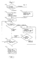
- Figure 1 illustrates diagrammatically the arrangement of a medium such as an optical disk used in one embodiment of the invention.
- a medium such as an optical disk used in one embodiment of the invention.
- a plurality of partitions are formed in one volume, and the file management is conducted in the unit of partition.
- a general purpose OS such as the MS-DOS in which the maximum capacity of the logical drive is restricted
- the entire volume is divided into several partitions, and each partition is regarded as one logical drive when performing the file management.
- one partition is assigned to the entire volume except the case wherein the division of the volume into partitions is necessary.
- the defect control can be performed in either of two operation modes, the automode, and the host mode.
- the automode an optical disk control unit automatically executes the process of substituting a defective sector with another one, according to the procedure incorporated in the unit.
- the host mode the host computer executes the substituting process according to a specific procedure designated by the OS or application program.
- These operation modes can be set in the unit of partition.
- one or more alternative zones are formed as a unit for performing the substitution of a defective sector. The number of the alternative zones depends on the capacity of the partition or the occurrence rate of a defective sector.
- the alternative zone comprises: a prime area in which user data are recorded; a primary spare area in which alternative sectors are recorded; and a primary defect list area in which a primary defect list storing the relationship between defective sectors and alternative sectors is recorded. If one partition comprises two or more alternative zones, the prime areas of the alternative zones are successively allocated so that the user areas in which user data are recorded are formed continuously in one partition.
- a primary defect list having a capacity corresponding to one sector (1 KB) can register a maximum of 120 defective sectors, and the rate of defective sectors is permitted to a maximum of 0.4%.
- the maximum capacity of a prime area of each alternative zone is given as follows.
- a partition a is designated to have a user area Ua of 20 MB, therefore, the partition a is composed of an alternative zone Za alone.
- the user area Ua equals a prime area Pa.
- a partition b designated to have a user area of 50 MB is composed of two alternative zones Zb and Zc which have a prime area Pb or Pc of 25 MB, respectively.
- the prime area Pb of the alternative zone Zb and the prime area Pc of the alternative zone Zc are successively formed so that the prime areas Pb and Pc constitute a user area Ub.
- the capacity of a primary defect list area varies depending on whether the medium is rewritable or not, but within the same medium it is identical in all alternative zones which is set to the automode. More specifically, in a medium which cannot be rewritten, a primary defect list area can be rewritten the number of times which equals the number of registered defective sectors, therefore, the number of sectors allocated in a primary defect list equals the maximum number (i.e., 120) of defective sectors the data of which can be registered in the primary defect list, resulting in that the capacity of the primary defect list area is 120 KB. In a medium which can be rewritten more than 120 times, a primary defect list is updated in a same area so that the capacity of the primary defect list area equals that of one sector (i.e., 1 KB).
- the capacity of a primary spare area also varies depending on whether the medium is rewritable or not, but it is common in all alternative zones which are set to the automode. For example, in spite that the number of rewriting a medium is restricted to 100,000 times on an average, it is often that such a medium is requested to be rewritten more than 100,000 times. In such a case, defective sectors are substituted with alternative sectors in a primary spare area, and some of these alternative sectors may again become defective sectors as the number of rewriting increases, thereby necessitating further alternative sectors to be allocated in the primary spare area. Hence, the number of alternative sectors allocated in a primary spare area are increased, in proportion to the required rewriting number, to that greater than the maximum number of registered defective sectors.
- a partition c shown in Fig. 1 wherein the host mode is set is assigned with a alternative zone Zd having only a prime area Pd the capacity of which is the same as that of a user area Uc. Since this partition has no primary defect list area, the capacity of a prime area is not limited.
- the secondary alternative area SSa comprises a secondary spare area SSs for recording alternative sectors, and a secondary defect list area SSd for recording secondary defect list which store the relationship between defective sectors and alternative sectors.
- the capacity of each of these areas is determined according to the characteristics of the medium in the same manner as the primary defect list areas and primary spare areas.
- a volume control area is formed at the beginning of the volume.
- the volume control area manages the above-mentioned partitions, alternative zones and secondary alternative area, and as well as an unused area wherein any partition has not been allocated.
- FIG. 2 shows a volume control area useful in an embodiment of the invention.
- the volume control area of Fig. 2 is composed of a partition control area and an alternative zone control area.
- a partition control block holding data which are used in the file management by the host computer is recorded, whereas, in the alternative zone control area, an alternative control block holding data necessary for the defect management is recorded.
- control data regarding the volume such as the capacity of the volume, the number of the registered partitions, and data of the unused area (e.g., the beginning address and the capacity) are recorded as a block header.
- This block header is followed by a partition description holding the control information of each partition.
- Each partition description contains a partition ID of the corresponding partition, a defect management mode for distinguishing the operation mode of the defect management, and control information of the user area (e.g., the beginning address and the capacity), etc.
- control information of the user area e.g., the beginning address and the capacity
- control data regarding the alternative zones such as geometrical parameters of disk including the number of tracks per volume and number of sectors per track, the number of registered alternative zones, the capacity of the primary defect list area and primary spare area, and control information of the unused area and secondary alternative area (e.g., the beginning address and the capacity) are recorded as a block header.
- This block header is followed by an alternative zone description holding the control information of each alternative zone.
- Each alternative zone description contains the beginning addresses of the primary defect lists and primary spare areas for constituting the corresponding alternative zones, the control information of the prime areas (e.g., the beginning address and the capacity), and a defect management mode for distinguishing the operation mode of the defect management. Since a primary defect list area and primary spare area are not assigned in the alternative zone set in the host mode, the beginning addresses of the primary defect list area and primary spare area in the alternative zone description are not actually given.
- Figure 3 shows another volume control area useful in an embodiment of the invention.
- the volume control area of Fig. 3 records a volume control block all control data regarding the volume.
- control data regarding the entire disk such as the geometrical parameters of the disk including the number of tracks per volume and the number of sectors per track, the number of registered partitions, the capacities of the primary defect list area and primary spare area, and control information of the unused area and secondary alternative area (e.g., the beginning address and the capacity) are recorded as a block header.
- This block header is followed by a partition description holding the control information of each partition.
- each partition description the partition ID of the corresponding partition, the defect management mode for distinguishing the operation mode of the defect management, the number of registered alternative zones, the control information of the user area (e.g., the beginning address and the capacity), and other control information of the entire partition are recorded as a partition header.
- This partition header is followed by the record of the alternative zone description holding the control information of each alternative zone constituting the partition.
- This alternative zone description contains the beginning addresses of the primary defect list areas and primary spare areas for constituting the corresponding alternative zones, and the control information of the prime areas (e.g., the beginning address and the capacity).
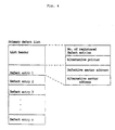
- Figure 4 illustrates a primary defect list.
- the number of defective entries and an alternative pointer indicating the address of the alternative sector to be used next are recorded as a list header.
- This list header is followed by defect entries each of which contains the address of the corresponding defective sector and the address of the alternative sector for substituting is.
- the secondary defect list has the same data structure as the primary defect list described above.
- FIG. 5 is a block diagram of an optical disk controller 1 used in an embodiment of the invention.
- the controller 1 comprises a main control unit 2 having a microprocessor for controlling the optical disk controller 1 according to the control sequence stored therein, a host interface circuit 4, a transfer data buffer 5, a control data buffer 6, an error detection and correction circuit 7, and a recording and reproducing control circuit 8. These components are interconnected by internal buses 3.
- the main control unit 2 exchanges drive commands and drive sense data with an optical disk drive 10 by way of a drive interface 9.
- the transfer data buffer 5 stores recorded/reproduced data to be transferred to and from a host computer 12.
- the control data buffer 6 contains the alternative zone control block, volume control block, primary defect list and secondary defect list which are used as the disk control information by the main control unit 2.
- the host interface circuit 4 is connected to the host computer 12 via a host interface 11 such as SCSI, and exchanges the control information such as device command and sense data with the main control unit 2, and also transfers recorded/reproduced data to the transfer data buffer 5 through the internal bus
- the error detection and correction circuit 7 reads out data to be recorded from the transfer data buffer 5 or control data buffer 6 through the internal bus 3, and adds an error detection and correction code to the data.
- the recording and reproducing control circuit 8 reads out the data to which an error detection and correction code has been attached, from the transfer data buffer 5 or control data buffer 6, and transfers them through the drive interface 9 to the optical disk drive 10 in which an optical disk 13 has been mounted.
- the recording and reproducing control circuit 8 demodulates reproduced data which have been transferred from the optical disk drive 10 through the drive interface 9, and then writes demodulated data into the transfer data buffer 5 or control data buffer 6.
- the error detection and correction circuit 7 reads demodulated data from these buffers, and detects and corrects errors in the data by using the error detection and correction code.
- the operation of the optical disk controller 1 will be described by way of illustrating two examples.
- the partition control block to be used in the file management and the alternative zone control block to be used in the defect management are recorded in the volume control area.
- the volume control block holding all control data necessary for the volume control is recorded in the volume control area, as shown in Fig. 3.
- the volume control block, partition control block, the alternative zone control block, primary defect list and secondary defect list have a capacity corresponding to one sector.
- the operation for a rewritable optical disk will be described first, followed by a description for a write-once optical disk.
- the first example is described below with respect to the operations of reading control data, registering partitions, and recording and reproducing a file accompanied by the substitution process of defective sectors.
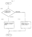
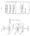
- the action of the optical disk controller 1 for reading out the alternative zone control block and secondary defect list into the control data buffer 6 at the time of loading the disk is explained with reference to the flow chart of Fig. 6.
- the file reading-out operation is executed from the partition where the automode is set as the operation mode of the defect management.
- the partition where the host mode is set as the operation mode of the defect management there is no possibility of accessing the alternative area. Therefore, the sectors assigned as a file reproducing area are subjected to only the same data reproduction operation as in procedure (Y).
- the operation of searching the primary defect list during the file recording operation and reproducing operation in the partition where the defect management is set to the automode is supplementarily described below.
- the operation of searching the primary defect list is always conducted prior to the data recording operation or reproducing operation.
- the primary defect list is stored in the control data buffer 6.
- the main control unit 2 interprets the device command, and judges whether the primary defect list of the alternative zone containing the recording area or reproducing area of the file is stored in the control data buffer 6 or not.
- steps (N) and (P) in Fig. 9 or step (W) in Fig. 10 may be skipped.
- the file recording area and reproducing area are supposed to be present in a single alternative zone. Actually, however, if the partition is divided into plural alternative zones as shown in the partition b in Fig. 1, the file recording area or reproducing area may spread over plural alternative zones. In such a case, all the related primary defect lists must be searched and read out.
- the volume control block for holding all control information necessary for volume control is recorded in the volume control area as shown in Fig. 3.
- the second example differs in the operation of reading the volume control block and also in the operation of registering a new partition.
- the operation of reading the volume control block when loading the disk can be explained by replacing the alternative zone control block with the volume control block, and by replacing the alternative zone control area with the volume control area in the process shown in Fig. 6.
- the main control unit 2 searches the volume control area to read out the volume control block, and stores them in the control data buffer 6.
- the main control unit 2 fetches the secondary defect list and stores it in the control data buffer 6.
- the main control unit 2 generates in the control data buffer 6 a volume control block having only a volume header or a secondary defect list having only a list header.
- the host computer 12 sends out a device command (MODE SENSE Command) for obtaining the control data of the partition formed on the disk.
- the main control unit 2 interprets the device command taken in the host interface circuit 4, and, as shown in Fig.
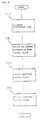
- the operation of registering a partition is executed as follows.
- the host computer 12 generates and sends out a device command (ASSIGN PARTITION Command) carrying the beginning address of the unused area read out from the header of the partition control block stored inside, the capacity of the partition to be registered, and the operation mode of the defect management.
- the main control unit 2 reads out and interprets the device command taken into the host interface circuit 4, and assigns certain alternative zones from the beginning of the unused area, depending on the operation mode of the defect management specified by the device command and the capacity of the partition.
- the main control unit 2 then generates a partition description holding the control data of the partition newly assigned, and updates the volume control block in the control data buffer 6.
- the main control unit 2 starts the error detection and correction circuit 7 and the recording and reproducing control circuit 8, and records the updated volume control block in the volume control area, and finishes the execution of the device command.
- the host computer 12 sends out a device command (MODE SENSE Command) in order to confirm the registered partition, and the main control unit 2 generates again the partition control block, as shown in Fig. 2, from the volume control block stored in the control data buffer 6, and sends it out to the host computer 12 as the mode sense data.
- the host computer 12 updates the partition control block stored therein on the basis of the contents of the received mode sense data, and terminates the operation of registering a partition.
- FIG. 11 illustrates a volume control area formed in a write-once optical disk. As shown in Fig. 11, many areas for recording volume control blocks are assigned in the volume control area.
- the volume control block In the operation of recording a new partition, the volume control block is updated and recorded by using unused sectors consecutively from one end of the volume control area. Therefore, many volume control blocks over generations are recorded in the volume control area, and the latest one among them is that recorded immediately before the unused area.
- the data reproduction operation In the operation of reading the volume control block when an optical disk is loaded, the data reproduction operation is executed consecutively from the sector positioned at one end of the volume control area, and the one which is reproduced last and positioned immediately before the unused sectors is regarded as the latest volume control block, and is stored in the control data buffer 6.
- the same data structure and recording and reproducing procedure are applied to the partition control block, alternative zone control block, primary defect list, secondary defect list and other control data.
Description
- This invention relates to a method of recording and reproducing information in which information is recorded in and reproduced from a disk-shaped information recording medium in sector units or on a sector by sector basis, and to an apparatus for performing the same.
- From WO-A-84/00628 a method and an apparatus is known for avoiding assessing of defective locations in disks and other storage media. The storage media used with this known method and apparatus has addressable locations and also a table of addresses of defective locations associated therewith. According to this known method an address for accessing a location in the storage media is produced and the table is consulted to determine defective locations that impact the obtained address. Moreover the obtained address for the defective locations that impact the obtained address is compensated and the storage media location designated by the compensated address is assessed. The apparatus for carrying through this method comprises a disk file controller which uses manufacturer-provided information about the location of defects to construct a sequentially ordered list of addresses of defective storage locations in the disk, wherein the list is also stored in a table in the disk. During the use of the disk, the disk file controller reads the table of defects into its memory and uses it to translate virtual addresses into real addresses. The translation process skips over real addresses of defective locations. The virtual addresses are translated into a real address by being incremented by the number of defects whose addresses are lower than the real address. Subsequent contiguous virtual addresses are translated into real addresses by being incremented by the number of contiguous defective locations that follow the location associated with the preceding virtual address. Addresses of new defects found during the use of the disk are stored by the disk file controller in temporary storage on the disk and are incorporated into the defect table when the disk is taken out of service.
- In a further conventional information recording and reproducing apparatus as it is known from "Disk Operating System Technical Reference", IBM Corporation, 1984, 1985, using an information recording medium (hereinafter, referred to as merely "a medium") such as a magnetic disk and floppy disk, the file managment including the defective sector management is effected by using, for example, the MS-DOS (trademark) of Microsoft Corp. which is known as a general-purpose OS for a personal computer. In the MS-DOS, a directory area for recording management information and a data area for recording file data area formed on the medium. A file allocation table (FAT) area is also formed in the medium to record a FAT for controlling the status of the data area which is divided in cluster units. Each entry of the FAT (hereinafter, referred too as "a FAT entry") which corresponds to each of the clusters one by one manages the status information (used/unused) of each cluster and the linkage information of a plurality of clusters which are used in recording a file. In such a medium, a defective sector may occur due to flaws, contamination or deterioration of the recording material. When a cluster contains a defective sector, an identification flag is recorded in the FAT entry corresponding to the cluster, to manage such a defective sector. When a medium is formatted to initialize FAT entries, an unused flag meaning that a cluster is unused is recorded in FAT entries corresponding to clusters containing no defective sector, and a defect flag in FAT entries corresponding to clusters containing a defective sector. When recording a new file, FAT entries having the unused flag the number of which corresponds to the size of the new file are sequentially retrieved from the beginning of a FAT: In this operation, FAT entries having the defect flag are skipped so that defective sectors will not be used in recording the new file. After the data of the new file are recorded in unused clusters, the FAT is updated by rewriting the linkage information which describes the new status of the linkage of the clusters.
- In a medium such as a write-once optical disk in which recorded information cannot be rewritten, the contents stored in one region of a FAT cannot be updated in the same region. Therefore, the afore-described management technique of a defective sector in a conventional file management system is not applicable to such a medium.
- A medium such as a rewritable optical disk in which recorded information can be rewritten incurs a possibility that the occurrence of defective sectors may suddenly increase after the rewrite operation has been conducted tens or hundreds of thousands times. In such a medium, a FAT area is rewritten on each record or update operation so that the number of rewriting the FAT becomes extremely large, resulting in a greater possibility that a defective sector will occur in the FAT. However, a conventional file management system has no alternative means for a defective sector which may occur in a FAT area.
- Thus, the invention described herein makes possible the objectives of:
- (1) providing a method and apparatus of managing defective sectors in a disk-shaped information recording medium which can manage defective sectors even when the medium is a non-rewritable one;
- (2) providing a method and apparatus of managing defective sectors in a disk-shaped information recording medium which can manage defective sectors even when the number of rewriting the contents of the medium is limited;
- This invention may be better understood and its numerous objects and advantages will become apparent to those skilled in the art by reference to the accompanying drawings as follows:
- Figure 1 is a diagram illustrating the area arrangement of an information recording medium used in one embodiment of the invention.
- Figure 2 is a diagram illustrating a volume control area in a first embodiment of the invention.
- Figure 3 is a diagram illustrating a volume control block in a second embodiment of the invention.
- Figure 4 is a diagram illustrating a primary defect list.
- Figure 5 is a block diagram of an optical disk control apparatus according to the invention.
- Figure 6 is a flow chart of the operation of reading an alternative zone control block.
- Figure 7 is a flow chart of the operation of reading a partition control block.
- Figure 8 is a flow chart of the operation of registering a partition.
- Figure 9 is a flow chart of the operation of recording a file.
- Figure 10 is a flow chart of the operation of reproducing a file.
- Figure 11 is a diagram illustrating the recording area of control data in a write-once optical disk.
- Figure 1 illustrates diagrammatically the arrangement of a medium such as an optical disk used in one embodiment of the invention. In the medium of Fig. 1, a plurality of partitions are formed in one volume, and the file management is conducted in the unit of partition. When a medium such as an optical disk apparatus having a capacity of hundreds of MB is controlled by a general purpose OS such as the MS-DOS in which the maximum capacity of the logical drive is restricted, the entire volume is divided into several partitions, and each partition is regarded as one logical drive when performing the file management. In the following description, one partition is assigned to the entire volume except the case wherein the division of the volume into partitions is necessary.
- According to the invention, the defect control can be performed in either of two operation modes, the automode, and the host mode. In the automode, an optical disk control unit automatically executes the process of substituting a defective sector with another one, according to the procedure incorporated in the unit. By contrast, in the host mode, the host computer executes the substituting process according to a specific procedure designated by the OS or application program. These operation modes can be set in the unit of partition. In a partition in which the automode is set, one or more alternative zones are formed as a unit for performing the substitution of a defective sector. The number of the alternative zones depends on the capacity of the partition or the occurrence rate of a defective sector. The alternative zone comprises: a prime area in which user data are recorded; a primary spare area in which alternative sectors are recorded; and a primary defect list area in which a primary defect list storing the relationship between defective sectors and alternative sectors is recorded. If one partition comprises two or more alternative zones, the prime areas of the alternative zones are successively allocated so that the user areas in which user data are recorded are formed continuously in one partition.
- A specific example of the area allocation will be described with reference to Fig. 1. In this example, a primary defect list having a capacity corresponding to one sector (1 KB) can register a maximum of 120 defective sectors, and the rate of defective sectors is permitted to a maximum of 0.4%. The maximum capacity of a prime area of each alternative zone is given as follows.

When a partition a is designated to have a user area Ua of 20 MB, therefore, the partition a is composed of an alternative zone Za alone. In this case, the user area Ua equals a prime area Pa. A partition b designated to have a user area of 50 MB is composed of two alternative zones Zb and Zc which have a prime area Pb or Pc of 25 MB, respectively. As shown in Fig. 1, the prime area Pb of the alternative zone Zb and the prime area Pc of the alternative zone Zc are successively formed so that the prime areas Pb and Pc constitute a user area Ub. - The capacity of a primary defect list area varies depending on whether the medium is rewritable or not, but within the same medium it is identical in all alternative zones which is set to the automode. More specifically, in a medium which cannot be rewritten, a primary defect list area can be rewritten the number of times which equals the number of registered defective sectors, therefore, the number of sectors allocated in a primary defect list equals the maximum number (i.e., 120) of defective sectors the data of which can be registered in the primary defect list, resulting in that the capacity of the primary defect list area is 120 KB. In a medium which can be rewritten more than 120 times, a primary defect list is updated in a same area so that the capacity of the primary defect list area equals that of one sector (i.e., 1 KB).
- The capacity of a primary spare area also varies depending on whether the medium is rewritable or not, but it is common in all alternative zones which are set to the automode. For example, in spite that the number of rewriting a medium is restricted to 100,000 times on an average, it is often that such a medium is requested to be rewritten more than 100,000 times. In such a case, defective sectors are substituted with alternative sectors in a primary spare area, and some of these alternative sectors may again become defective sectors as the number of rewriting increases, thereby necessitating further alternative sectors to be allocated in the primary spare area. Hence, the number of alternative sectors allocated in a primary spare area are increased, in proportion to the required rewriting number, to that greater than the maximum number of registered defective sectors. For example, if the required rewriting number is 1,000,000, alternative sectors the number of which is ten times the maximum number of registered defective sectors (that is, 1,200 sectors) are allocated in a primary spare area, resulting in that the capacity of the primary spare area is 1.2 MB. In contrast, in a medium which is not rewritable or not limited in the number of rewritings, alternative sectors in the same number as the maximum number of registered defective sectors are allocated in a primary spare area, and its capacity is 120 KB.
- A partition c shown in Fig. 1 wherein the host mode is set is assigned with a alternative zone Zd having only a prime area Pd the capacity of which is the same as that of a user area Uc. Since this partition has no primary defect list area, the capacity of a prime area is not limited.
- If defective sectors are detected in a greater number than a fixed value from a prime area or a primary spare area wherein the automode is set, it become impossible to conduct the process of substituting defective sectors with alternative sectors within the same alternative zone. This may be solved by forming a secondary alternative area SSa which records the data of defective sectors which overflow the alternative zone. The secondary alternative area SSa comprises a secondary spare area SSs for recording alternative sectors, and a secondary defect list area SSd for recording secondary defect list which store the relationship between defective sectors and alternative sectors. The capacity of each of these areas is determined according to the characteristics of the medium in the same manner as the primary defect list areas and primary spare areas.
- A volume control area is formed at the beginning of the volume. The volume control area manages the above-mentioned partitions, alternative zones and secondary alternative area, and as well as an unused area wherein any partition has not been allocated.
- Figure 2 shows a volume control area useful in an embodiment of the invention. The volume control area of Fig. 2 is composed of a partition control area and an alternative zone control area. In the partition control area, a partition control block holding data which are used in the file management by the host computer is recorded, whereas, in the alternative zone control area, an alternative control block holding data necessary for the defect management is recorded. At the beginning of the partition control block, control data regarding the volume such as the capacity of the volume, the number of the registered partitions, and data of the unused area (e.g., the beginning address and the capacity) are recorded as a block header. This block header is followed by a partition description holding the control information of each partition. Each partition description contains a partition ID of the corresponding partition, a defect management mode for distinguishing the operation mode of the defect management, and control information of the user area (e.g., the beginning address and the capacity), etc. When a partition is divided into plural alternative zones, such as in the partition b, the beginning address of the prime area Pb is registered as the beginning address of the user area.
- At the beginning of the alternative zone control block, control data regarding the alternative zones such as geometrical parameters of disk including the number of tracks per volume and number of sectors per track, the number of registered alternative zones, the capacity of the primary defect list area and primary spare area, and control information of the unused area and secondary alternative area (e.g., the beginning address and the capacity) are recorded as a block header. This block header is followed by an alternative zone description holding the control information of each alternative zone. Each alternative zone description contains the beginning addresses of the primary defect lists and primary spare areas for constituting the corresponding alternative zones, the control information of the prime areas (e.g., the beginning address and the capacity), and a defect management mode for distinguishing the operation mode of the defect management. Since a primary defect list area and primary spare area are not assigned in the alternative zone set in the host mode, the beginning addresses of the primary defect list area and primary spare area in the alternative zone description are not actually given.
- Figure 3 shows another volume control area useful in an embodiment of the invention. The volume control area of Fig. 3 records a volume control block all control data regarding the volume. At the beginning of the volume control block, control data regarding the entire disk such as the geometrical parameters of the disk including the number of tracks per volume and the number of sectors per track, the number of registered partitions, the capacities of the primary defect list area and primary spare area, and control information of the unused area and secondary alternative area (e.g., the beginning address and the capacity) are recorded as a block header. This block header is followed by a partition description holding the control information of each partition. In each partition description, the partition ID of the corresponding partition, the defect management mode for distinguishing the operation mode of the defect management, the number of registered alternative zones, the control information of the user area (e.g., the beginning address and the capacity), and other control information of the entire partition are recorded as a partition header. This partition header is followed by the record of the alternative zone description holding the control information of each alternative zone constituting the partition. This alternative zone description contains the beginning addresses of the primary defect list areas and primary spare areas for constituting the corresponding alternative zones, and the control information of the prime areas (e.g., the beginning address and the capacity).
- Figure 4 illustrates a primary defect list. At the beginning of the primary defect list, the number of defective entries and an alternative pointer indicating the address of the alternative sector to be used next are recorded as a list header. This list header is followed by defect entries each of which contains the address of the corresponding defective sector and the address of the alternative sector for substituting is. The secondary defect list has the same data structure as the primary defect list described above.
- Figure 5 is a block diagram of an
optical disk controller 1 used in an embodiment of the invention. Thecontroller 1 comprises amain control unit 2 having a microprocessor for controlling theoptical disk controller 1 according to the control sequence stored therein, ahost interface circuit 4, atransfer data buffer 5, acontrol data buffer 6, an error detection andcorrection circuit 7, and a recording and reproducingcontrol circuit 8. These components are interconnected byinternal buses 3. Themain control unit 2 exchanges drive commands and drive sense data with anoptical disk drive 10 by way of adrive interface 9. Thetransfer data buffer 5 stores recorded/reproduced data to be transferred to and from ahost computer 12. Thecontrol data buffer 6 contains the alternative zone control block, volume control block, primary defect list and secondary defect list which are used as the disk control information by themain control unit 2. Thehost interface circuit 4 is connected to thehost computer 12 via ahost interface 11 such as SCSI, and exchanges the control information such as device command and sense data with themain control unit 2, and also transfers recorded/reproduced data to thetransfer data buffer 5 through theinternal bus 3. - When recording data, the error detection and
correction circuit 7 reads out data to be recorded from thetransfer data buffer 5 orcontrol data buffer 6 through theinternal bus 3, and adds an error detection and correction code to the data. The recording and reproducingcontrol circuit 8 reads out the data to which an error detection and correction code has been attached, from thetransfer data buffer 5 orcontrol data buffer 6, and transfers them through thedrive interface 9 to theoptical disk drive 10 in which anoptical disk 13 has been mounted. When reproducing data, the recording and reproducingcontrol circuit 8 demodulates reproduced data which have been transferred from theoptical disk drive 10 through thedrive interface 9, and then writes demodulated data into thetransfer data buffer 5 orcontrol data buffer 6. The error detection andcorrection circuit 7 reads demodulated data from these buffers, and detects and corrects errors in the data by using the error detection and correction code. - The operation of the
optical disk controller 1 will be described by way of illustrating two examples. In a first example, as shown in Fig. 2, the partition control block to be used in the file management and the alternative zone control block to be used in the defect management are recorded in the volume control area. By contrast, in a second example, the volume control block holding all control data necessary for the volume control is recorded in the volume control area, as shown in Fig. 3. For the sake of simplicity of explanation, it is supposed that the volume control block, partition control block, the alternative zone control block, primary defect list and secondary defect list have a capacity corresponding to one sector. In the following, the operation for a rewritable optical disk will be described first, followed by a description for a write-once optical disk. - The first example is described below with respect to the operations of reading control data, registering partitions, and recording and reproducing a file accompanied by the substitution process of defective sectors. To begin with, the action of the
optical disk controller 1 for reading out the alternative zone control block and secondary defect list into thecontrol data buffer 6 at the time of loading the disk is explained with reference to the flow chart of Fig. 6. - (A) When the
optical disk drive 10 detects that a new disk is loaded in the apparatus, it notices the loading of the disk to themain control unit 2 through thedrive interface 9. Themain control unit 2, receiving this information, sends out a drive command to theoptical disk drive 10 through thedrive interface 9 to seek the alternative zone control area. When theoptical disk drive 10 notices the end of the seek operation to themain control unit 2 through thedrive interface 9, themain control unit 2 specifies the address of the alternative zone control area as the target sector address to the recording and reproducingcontrol circuit 8, and starts the data reproducing operation. The recording and reproducingcontrol circuit 8 detects the target sector, and attempts to reproduce the data from the target sector. - (B) When the alternative zone control area has not yet been recorded, the
main control unit 2 detects the nonrecord flag sent out from the recording and reproducingcontrol circuit 8, and consequently produces in thecontrol data buffer 6 an alternative zone control block having only a block header in which the number of registered alternative zones is zero, and a secondary defect list having only a list header in which the number of registered defect entries is zero are generated. - (C) On the other hand, when the alternative zone control area has been already recorded, the recording and reproducing
control circuit 8 demodulates the data read out from theoptical disk drive 10, and transfers them to thecontrol data buffer 6. When the transfer of the reproduced data is completed, themain control unit 2 starts the error detection andcorrection circuit 7 to correct errors in the reproduced data, and the alternative zone control block which has been read out is stored in thecontrol data buffer 6. - (D) When the alternative zone control block is read out, the
main control unit 2 reads out the control data in the secondary alternative area recorded in the alternative zone control block. Themain control unit 2, in the same procedure as in (A), seeks the secondary defect list area, and attempts to reproduce the secondary defect list. - (E) If the secondary defect list area has not yet been recorded, a nonrecord flag sent out from the recording and reproducing
control circuit 8 is detected, and consequently themain control unit 2 generates in the control data buffer 6 a secondary defect list having only a list header in which the number of defect entries registered in the secondary defect list is zero. - (F) On the other hand, when the secondary defect list area has been already recorded, the recording and reproducing
control circuit 8 demodulates the data read out from theoptical disk drive 10, and transfers them to thecontrol data buffer 6. When the transfer of the reproduced data is over, themain control unit 2 starts the error detection andcorrection circuit 7 to correct errors in the reproduced data, and the secondary defect list is stored in thecontrol data buffer 6.
As a result of the above-described operation, the alternative zone control block and secondary defect list which have been read out from the optical disk are stored in thecontrol data buffer 6. If the alternative zone control area or the secondary defect list area is in the unrecorded state, the alternative zone control block or secondary defect list meaning the unused state is generated in thecontrol data buffer 6.
Then, the operation of the host computer for reading out the partition control block which is executed prior to the operation of recording partitions or recording and reproducing a file will be described with reference to the flow chart of Fig. 7. - (G) The
host computer 12 sends out a device command (READ Command) specifying the partition control area as the data reproducing area. Themain control unit 2 reads out and interprets the device command taken into thehost interface circuit 4, and then seeks the partition control area in the same procedure as in (A), and attempts to reproduce the partition control block. - (H) When the partition control area has been already recorded, the recording and reproducing
control circuit 8 demodulates the data read out from theoptical disk drive 10, and transfers them to thetransfer data buffer 5. Themain control unit 2 starts the error detection andcorrection circuit 7 to correct errors in the reproduced data. Then, themain control unit 2 starts thehost interface circuit 4 to transfer the reproduced data from thetransfer data buffer 5 to thehost computer 12. The reproduced data is stored in thehost computer 12 as the partition control block. - (I) On the other hand, if the partition control area has not yet been recorded, the
main control unit 2 detects a nonrecord flag sent out from the recording and reproducingcontrol circuit 8, and generates sense data meaning that the target sector is in the unrecorded state, and informs it to thehost computer 12 through thehost interface circuit 4. Thehost computer 12, in turn, detects the unrecorded state of the partition control area, and generates a volume control block having only a block header. In this block header, the number of registered partitions is given as zero, and the control data of the unused area meaning that the entire volume is in the unused state is registered.
In this processing sequence, the host computer preserves the partition control block therein.
Next, the operation of thehost computer 12 for registering a new partition is described below with reference to the flow chart of Fig. 8. - (J) The
host computer 12 generates the beginning address of the unused area read out from the block header of the partition control block held in the computer, the capacity of the partition to be registered, and the device command (ASSIGN PARTITION Command) which contains the operation mode of the defect management of the defective sector, and sends out the device command to thehost interface circuit 4. Themain control unit 2 reads out and interprets the device command from thehost interface circuit 4, and interprets it to assign certain alternative zones from the beginning of the unused area, depending on the operation mode of the defect management specified by the device command and the capacity of the partition. Themain control unit 2 then generates the alternative zone description holding the control data of the newly assigned alternative zone, and updates the alternative zone control block held in thecontrol data buffer 6. - (K) Thereafter, the
main control unit 2 sends out a drive command to theoptical disk drive 10, and executes the seek operation again in the alternative zone control area. When the seek operation is over, themain control unit 2 starts the error detection andcorrection circuit 7 to attach an error detection and correction code to the alternative zone control block in thecontrol data buffer 6 which is the data to be recorded. Further, themain control unit 2 designates the address in the alternative zone control area as the target sector address to the recording and reproducingcontrol circuit 8, and starts the data recording operation, thereby recording the recorded data in the alternative zone control area. - (L) The
main control unit 2 generates the sense data holding the beginning address of the user area in the newly formed partition and the control data of the unused area after the registration of the partition, and transfers it to thehost computer 12 by way of thehost interface circuit 4. Thehost computer 12 rewrites the block header of the partition control block relating to the number of registered partitions and the control data of the unused area, according to the transferred sense data, and additionally registers the partition description in which the control data of a new partition is held, thereby updating the partition control block. - (M) In order to record the updated partition control block, the
host computer 12 sends out a device command (WRITE Command) specifying the partition control area as the data recording area. Themain control unit 2 reads out the device command from thehost interface circuit 4, and interprets it to send out the drive command to theoptical disk drive 10, thereby executing the seek operation against the partition control area. When the seek action is over, themain control unit 2 starts thehost interface circuit 4 to transfer the partition control block from thehost computer 12 to thetransfer data buffer 5. Then, themain control unit 2 starts the error detection andcorrection circuit 7 to add an error detection and correction code to the recorded data in thetransfer data buffer 5. Further, themain control unit 2 specifies an address of the partition control area as the target sector address to the recording and reproducingcontrol circuit 8, and executes the data recording operation, thereby recording the partition control block in the partition control area.
By this processing sequence for registering partitions, a new alternative zone is assigned in the unused area in the disk, and the updated partition control block and alternative zone control block area are recorded.
Referring now to the flow chart of Fig. 9, the operation of recording data in a file accompanied by the detection of a defective sector and the substitution thereof in a partition wherein the operation mode of the defect management is set to the automode. - (N) The
host computer 12 sends out the device command (WRITE Command) in which the file recording area is specified. Themain control unit 2 reads out the device command from thehost interface circuit 4, identifies the alternative zone containing the recording area of the file by referring to the alternative zone control block held in thecontrol data buffer 6, and reads out the alternative zone description holding the control data of the alternative zone. Next, in the same procedure as in (A), themain control unit 2 executes the seek action against the primary defect list area in this alternative zone, and attempts to reproduce the primary defect list. - (O) When the primary defect list area has been already recorded, the recording and reproducing
control circuit 8 demodulates the data read out from theoptical disk drive 10, and transfers them to thecontrol data buffer 6. Themain control unit 2 starts the error detection andcorrection circuit 7 to correct errors in the reproduced data. Thereafter, themain control unit 2 searches the primary defect list fetched to thecontrol data buffer 6 for defective sectors contained in the file recording area. If the number of the defect entries recorded in the primary defect list reaches the maximum number of defect entries that can be registered in the list, themain control unit 2 searches also the second defect list stored in thecontrol data buffer 6 for defective sectors contained in the file recording area. If defective sectors are found, themain control unit 2 reads out the defect entries which control such defective sectors, and holds them inside it. - (P) When the primary defect list area has not yet been recorded, the
main control unit 2 detects a nonrecord flag sent out from the recording and reproducingcontrol circuit 8, and then it is judged that the primary defect list is in the unrecorded state. The primary defect list having only the list header is generated in thecontrol data buffer 6. In this list header, the number of registered defect entries is given as zero, and the address of the first sector in the primary spare area is given as an alternative pointer. - (Q) The
main control unit 2 sends out a drive command to theoptical disk drive 10, and seeks the target sector which is the sector assigned as a file recording area. When the assigned sector is judged in the procedure of (O) to be a defective sector, themain control unit 2 sends out a drive command specifying an alternative sector replacing the defective sector as the target sector, and executes the seek operation against the primary spare area or secondary spare area. When the seek operation is over, themain control unit 2 starts thehost interface circuit 4 to transfer the data to be recorded from thehost computer 12 to thetransfer data buffer 5. Themain control unit 2 starts the error detection andcontrol circuit 7 to add an error detection and correction code to the recorded data. Moreover, themain control unit 2 specifies the target sector address to the recording and reproducingcontrol circuit 8, and starts the data recording action, thereby recording data in the target sector. These data recording operations are executed on all sectors assigned as a file recording area. - (R) The
main control unit 2 sends out again a drive command to theoptical disk drive 10, and executes the operation of seeking the target sector which is the sector assigned as a file recording area. At this time, when the assigned sector is judged in the procedure of (O) to be a defective sector, themain control unit 2 sends out a drive command specifying an alternative sector replacing the defective sector as the target sector, and the seek operation is executed in the primary spare area or secondary spare area. When the seek operation is over, themain control unit 2 specifies the target sector address to the recording and reproducingcontrol circuit 8, and starts the data reproducing operation. The recording and reproducingcontrol circuit 8 demodulates the reproduced data transferred from theoptical disk drive 10, and sends them out to thetransfer data buffer 5. Then, themain control unit 2 starts the error detection andcorrection circuit 7, and attempts to detect errors contained in the reproduced data. If the degree of an error detected by the error detection andcorrection circuit 7 is smaller than the specified reference value (in other words, if the error can be corrected by the error detection and correction circuit 7), themain control unit 2 judges that the verify operation against the target sector has been normally terminated (i.e., without detecting any error). On the other hand, when an error exceeding the reference value is detected in the target sector, themain control unit 2 judges that the target sector is a defective sector, and holds the address of the defective sector. - (S) When a defective sector is detected, the
main control unit 2 refers to the list header of the primary defect list stored in thecontrol data buffer 6, and sequentially assigns to the detected defective sectors unused alternative sectors sequentially from one end of the primary spare area. Then, themain control unit 2 registers new defect entries into the primary defect list in thecontrol data buffer 6, and updates the list header. If no unused entry exists in the primary detect list or no unused sector in the primary spare area, the substitution operation is disabled. In such a case, unused alternative sectors are sequentially assigned to those defective sectors from one end of the secondary spare area to such defective sector. Themain control unit 2 then registers new defect entries in the secondary defect list stored in thecontrol data buffer 6 and updates the list header. - (T) The
main control unit 2 sends out a drive command to theoptical disk drive 10 to seek the assigned alternative sector. When the seek operation is over, themain control unit 2 starts the error detection andcorrection circuit 7 to add an error detection and correction code to the recorded data which have been stored in thetransfer data buffer 5 in the procedure of (Q), and thereafter specifies an alternative sector address as a target sector address to the recording and reproducingcontrol circuit 8, and executes the data recording operation. When the data recording operation is over, themain control unit 2 executes the verify operation against the alternative sector in the same way as the procedure of (R). - (U) When the verify operation on the target sector is normally terminated in the procedure (R), or when the substitution operation on the defective sector in which a verify error has been detected is finished in the procedure of (S) and (T), the
main control unit 2 executes the above-mentioned process on all sectors assigned as the file recording area. - (V) When the verify operation on all sectors and the substitution operation on the detected defective sectors are over, the
main control unit 2 checks if the primary defect list and secondary defect list have been updated or not in thecontrol data buffer 6. When the primary defect list has been updated, themain control unit 2 sends out a drive command to theoptical disk drive 10 to seek the primary defect list area. When the seek operation is over, themain control unit 2 starts the error detection andcorrection circuit 7, and adds the error detection and correction code to the primary defect list in thecontrol data buffer 6. Specifying the address in the primary defect list area as the target sector address to the recording and reproducingcontrol circuit 8 to start the data recording operation, the data are recorded in the primary defect list area. When the secondary defect list is updated, the secondary defect list in the secondary defect list area is updated and recorded in the same procedure as mentioned above.
In the afore-mentioned processing sequence, the recording operation of file is executed in the partition in which the operation mode of the defect management is set to the automode. The dependence of the allocation procedure of alternative sectors in procedure (S) on the area of detecting defective sectors will be supplementarily described. First, a defective sector detected from the prime area and that detected from the primary spare area have a different criterion for judging whether the defective sector can be replaced within the alternative zone or not. In other words, if a defective sector has been detected from the prime area, in order to replace this defective sector within the alternative zone, it is necessary that an unused alternative sector be present in the primary spare area, and that an unused entry be present in the primary defect list. On the other hand, if a defective sector has been detected from the primary spare area, this defective sector can be replaced within the alternative zone as far as an unused alternative sector is present in the primary spare area, because this alternative sector already has a defect entry in the primary defect list. According to this criterion, when a detected defective sector is judged to be unable to be replaced within the alternative zone, an alternative sector in the secondary spare area which sector is in the unused state is used. The second point is the processing sequence relating to the updation and record of the control data of a defective sector. When an alternative sector within a secondary spare area is assigned to a defective sector detected in the primary spare area, themain control unit 2 registers a new defect entry in the secondary defect list, and deletes the unnecessary defect entry from the primary defect list. On the other hand, when a defective sector is detected in the prime area, only the operation of registering a new defect entry in the secondary defect list is executed.
The recording operation of file in the partition in which the operation mode of the defect management is set to the host mode is executed as follows. Themain control unit 2 reads out a device command (WRITE Command) sent from thehost computer 12 from thehost interface circuit 4, and sends out a drive command to theoptical disk drive 10 to seek the target sector in which the data is to be recorded. When the end of the seek operation is noticed from theoptical disk drive 10, themain control unit 2 starts thehost interface circuit 4, and transfers the data to be recorded from thehost computer 12 into thetransfer data buffer 5. Then, themain control unit 2 starts the error detection andcorrection circuit 7 to add an error detection and correction code to the recorded data, and further starts the recording and reproducingcontrol circuit 8, thereby executing the data recording operation against the target sector assigned in the file recording area. When such a data recording operation has been conducted on all sectors assigned as a file recording area, themain control unit 2 executes the verify operation to all sectors in which data have been recorded. That is, themain control unit 2 starts the recording and reproducingcontrol circuit 8 to demodulate the reproduced data transferred from theoptical disk drive 10, and sends them to thetransfer data buffer 5. Then, themain control unit 2 starts the error detection andcorrection circuit 7, thereby attempting to detect errors contained in the reproduced data. When the error detection andcorrection circuit 7 detects from the target sector an error the degree of which exceeds the reference value, themain control unit 2 generates sense data meaning that this target sector is a defective sector, and notices it to thehost computer 12 through thehost interface circuit 4, thereby finishing the execution of the device command. At this time, thehost computer 12 executes the process of substituting defective sectors according to the procedure specified by the OS or application program.
In the partition where the automode is set as the operation mode of the defect management, the file reproduction operation accompanied by the operation of reproducing data from the alternative sector is explained below by referring to the flow chart of Fig. 10. - (W) The
host computer 12 sends out a device command (READ Command) specifying the file reproducing area. Themain control unit 2 reads out the device command from thehost interface circuit 4, and identifies the alternative zone containing the file reproducing area by referring to the alternative zone control block stored in thecontrol data buffer 6, and reads out the alternative zone description holding its control data. Next, in the same procedure as in (A), themain control unit 2 executes the seek operation against the primary defect list area of the alternative zone, and attempts to reproduce the primary defect list. When a nonrecord flag meaning that the target sector is unrecorded is sent out from the recording and reproducingcontrol circuit 8, themain control unit 2 detects that the primary defect list is in the unrecorded state, and judges that the defective sector is not present in the alternative zone containing the file reproducing area. - (X) When the primary defect list area has been already recorded, the recording and reproducing
control circuit 8 demodulates the data read out from theoptical disk drive 10, and transfers them to thecontrol data buffer 6. Themain control unit 2, starts the error detection andcorrection circuit 7, and corrects the errors in the reproduced data. Themain control unit 2 searches the primary defect list read out into thecontrol data buffer 6 for defective sectors contained in the file recording area. If the number of the registered defective entries reaches the maximum number of defect entries that can be registered in the primary defect list, themain control unit 2 searches the secondary defect list stored in thecontrol data buffer 6 for defective sectors contained in the file recording area also. When a defective sector is detected, themain control unit 2 reads out the defect entry controlling the defective sectors and store it therein. - (Y) The
main control unit 2 sends out a drive command to theoptical disk drive 10, and executes the seek operation against the target sector which is a sector assigned as a file reproducing area. When the assigned sector is judged to be a defective sector in the procedure of (X), themain control unit 2 sends a drive command for designating the alternative sector instead of the defective sector as the target sector, and seeks the primary spare area or secondary spare area. When the seek operation is over, themain control unit 2 specifies the target sector address to the recording and reproducingcontrol circuit 8, and starts the data reproducing operation. Next, the recording and reproducingcontrol circuit 8 demodulates the data transferred from theoptical disk drive 10, and sends them to thetransfer data buffer 5. Themain control unit 2 starts the error detection andcorrection circuit 7 to correct errors in the reproduced data. Thereafter, themain control unit 2 starts thehost interface circuit 4, and transfers the reproduced data from thetransfer data buffer 5. The data reproducing operation is executed on all sectors assigned as a file reproducing area. - According to this procedure, the file reading-out operation is executed from the partition where the automode is set as the operation mode of the defect management. On the other hand, in the partition where the host mode is set as the operation mode of the defect management, there is no possibility of accessing the alternative area. Therefore, the sectors assigned as a file reproducing area are subjected to only the same data reproduction operation as in procedure (Y).
- The operation of searching the primary defect list during the file recording operation and reproducing operation in the partition where the defect management is set to the automode is supplementarily described below. In the operating procedure described with reference to Figs. 9 and 10, the operation of searching the primary defect list is always conducted prior to the data recording operation or reproducing operation. However, once the file recording operation or file reproducing operation is executed, the primary defect list is stored in the
control data buffer 6. When the file recording operation or file reproducing operation is executed again in the same alternative zone, therefore, the operation of searching the primary defect list is not required. In other words, themain control unit 2 interprets the device command, and judges whether the primary defect list of the alternative zone containing the recording area or reproducing area of the file is stored in thecontrol data buffer 6 or not. When the primary defect list is found in thecontrol data buffer 6, steps (N) and (P) in Fig. 9 or step (W) in Fig. 10 may be skipped. Second, in the operating procedure described by referring to Figs. 9 and 10, the file recording area and reproducing area are supposed to be present in a single alternative zone. Actually, however, if the partition is divided into plural alternative zones as shown in the partition b in Fig. 1, the file recording area or reproducing area may spread over plural alternative zones. In such a case, all the related primary defect lists must be searched and read out. Third, in an apparatus for recording a file of a large capacity such as that for image data, it is often that data are divided so as to be stored in several files in view of the characteristics of a host computer. In such a case, it is predicted that the file recording areas and reproducing areas be continuous within a partition. Therefore, in both an alternative zone containing the file recording area and reproducing area and another alternative zone positioned ahead of that alternative zone, the process for reading out the primary defect list is executed continuously, resulting in that the number of executions of the seek operation between the primary defect list area and the prime area can be reduced, and the access time may be shortened. In such a case, it is preferable to dispose successively all primary defect list areas contained in a same partition. - The second example will be described. In the second example, the volume control block for holding all control information necessary for volume control is recorded in the volume control area as shown in Fig. 3. The second example, as compared with the first example, differs in the operation of reading the volume control block and also in the operation of registering a new partition. The operation of reading the volume control block when loading the disk can be explained by replacing the alternative zone control block with the volume control block, and by replacing the alternative zone control area with the volume control area in the process shown in Fig. 6. In sum, the
main control unit 2 searches the volume control area to read out the volume control block, and stores them in thecontrol data buffer 6. According to the control data of the secondary alternative area which are recorded in the volume control block, themain control unit 2 fetches the secondary defect list and stores it in thecontrol data buffer 6. On the other hand, when the volume control area or secondary defect list area is in the unrecorded state, themain control unit 2 generates in the control data buffer 6 a volume control block having only a volume header or a secondary defect list having only a list header. Next, in the state that the volume control block is stored in the control data buffer, thehost computer 12 sends out a device command (MODE SENSE Command) for obtaining the control data of the partition formed on the disk. Themain control unit 2 interprets the device command taken in thehost interface circuit 4, and, as shown in Fig. 2, generates a partition control block from the volume control block stored in thecontrol data buffer 6, and sends it out to thehost computer 12 as the mode sense data. As a result, the volume control block and secondary defect list are accepted into thecontrol data buffer 6, and thehost computer 12 stores the partition control block. - The operation of registering a partition is executed as follows. The
host computer 12 generates and sends out a device command (ASSIGN PARTITION Command) carrying the beginning address of the unused area read out from the header of the partition control block stored inside, the capacity of the partition to be registered, and the operation mode of the defect management. Themain control unit 2 reads out and interprets the device command taken into thehost interface circuit 4, and assigns certain alternative zones from the beginning of the unused area, depending on the operation mode of the defect management specified by the device command and the capacity of the partition. Themain control unit 2 then generates a partition description holding the control data of the partition newly assigned, and updates the volume control block in thecontrol data buffer 6. Themain control unit 2 starts the error detection andcorrection circuit 7 and the recording and reproducingcontrol circuit 8, and records the updated volume control block in the volume control area, and finishes the execution of the device command. Finally, thehost computer 12 sends out a device command (MODE SENSE Command) in order to confirm the registered partition, and themain control unit 2 generates again the partition control block, as shown in Fig. 2, from the volume control block stored in thecontrol data buffer 6, and sends it out to thehost computer 12 as the mode sense data. Thehost computer 12 updates the partition control block stored therein on the basis of the contents of the received mode sense data, and terminates the operation of registering a partition. - The above-mentioned description relates to a rewritable optical disk, and the control data of the volume control block, partition control block, alternative zone control block, primary defect list and secondary defect list are all supposed to be updated and recorded in the same area. However, in an information recording medium that is not rewritable such as a write-once optical disk, data cannot be updated or recorded within the same area. Hereinafter, the structure of the control data in a write-once optical disk and the recording and reproducing procedure therefor will be described by taking the volume control block as an example. Figure 11 illustrates a volume control area formed in a write-once optical disk. As shown in Fig. 11, many areas for recording volume control blocks are assigned in the volume control area. In the operation of recording a new partition, the volume control block is updated and recorded by using unused sectors consecutively from one end of the volume control area. Therefore, many volume control blocks over generations are recorded in the volume control area, and the latest one among them is that recorded immediately before the unused area. In the operation of reading the volume control block when an optical disk is loaded, the data reproduction operation is executed consecutively from the sector positioned at one end of the volume control area, and the one which is reproduced last and positioned immediately before the unused sectors is regarded as the latest volume control block, and is stored in the
control data buffer 6. The same data structure and recording and reproducing procedure are applied to the partition control block, alternative zone control block, primary defect list, secondary defect list and other control data.
According to the invention, defective sectors are managed by using alternative zones which are formed in accordance with the volume capacity or partition capacity and the occurrence rate of defective sectors. Hence, control data for the substitution of defective sectors (i.e., the capacity of the primary defect list) can always be small in size and fixed in length, thereby enabling the capacity of a buffer for storing the primary defect list to be small, and also enabling the operation of retrieving the primary defect list to be rapidly conducted to reduce the time required for the operation. When a non-rewritable medium such as a write-once optical disk is used, the use of such a compact prime defect list can reduce the capacity of a prime defect list area for recording new prime defect lists. When a medium in which the number of rewriting information is limited is used, the use of such a compact prime defect list can reduce the number of rewriting the primary defect list. According to the invention, further, the substitution of defective sectors are conducted on the basis of the hierarchical structure. Therefore, a medium in which many defective sectors may be locally generated can be easily handled. The present invention achieves the excellent defect management in an information recording medium in which the number of the rewriting operations is restricted or which is not rewritable.
Claims (22)
- A method of managing defective sectors in a disk-shaped information recording medium in which the recording and reproducing of information are conducted in units of a sector, comprising the steps of
allocating at least one alternative zone in said information recording medium, said alternative zone comprising: a prime area for recording user data, the number of non-defective sectors of said prime area is variable and corresponds to the occurrence rate of defective sectors and to the volume capacity or partition capacity; a primary spare area for recording alternative sectors which substitute defective sectors; and a primary defect list area for recording a primary defect list of a fixed length, said primary defect list holding the relations between defective sectors and alternative sectors,
managing defective sectors by substituting the defective sectors detected in said prime area with alternative sectors in said primary spare area, and by registering the defective sectors and the corresponding alternative sectors in said primary defect list,
allocating a secondary alternative area in said information recording medium, said secondary alternative area comprising: a secondary spare area for recording alternative sectors for substituting defective sectors which cannot be substituted in said alternative zone; and a secondary defect list area for recording a secondary defect list which holds the relations between defective sectors in said prime area and alternative sectors in said secondary spare area,
managing hierarchically defective sectors by substituting defective sectors which cannot be substituted in said alternative zone, with alternative sectors in said secondary alternative area, and by registering the defective sectors and the corresponding alternative sectors in said secondary defect list, and
managing all areas formed in the recording medium by allocating a volume control area in said information recording medium, and by recording volume control data in said volume control area, said volume control data including control data of said at least one alternative zone, the partitions, of the alternative zone said secondary alternative area and an unused area. - A method according to claim 1, wherein said volume control area is divided into a partition control area and an alternative zone control area, a partition control block holding control data necessary for the allocation of partitions and the recording and reproducing of a file is formed to be recorded in said partition control area, and an alternative zone control block, having control data necessary for the recording and reproducing of data including the allocation of partitions and the substitution of defective sectors is formed to be recorded in said alternative zone control area.
- A method according to claim 2, wherein a defect control mode for identifying an operation mode of the management of defective sectors is recorded as one part of partition control data and alternative zone control data, thereby enabling the operation mode of the management of substituting defective sectors to be set in units of a partition.
- A method according to claim 1, wherein a volume control block for storing control data necessary for the operation of recording and reproducing data is generated to be recorded in said volume control area, said operation including the allocation of partitions, the recording and reproducing of a file, and the substitution of a defective sector.
- A method according to claim 4, wherein a defect control mode for identifying an operation mode of the management of defective sectors is recorded as one part of volume control data, thereby enabling the operation mode of the management of substituting defective sectors to be set in units of a partition.
- A method according to claim 1, wherein the management of substituting defective sectors is conducted while at least one partition is divided into a plurality of alternative zones, and a plurality of prime areas are arranged successively in said partition.
- A method according to claim 1, wherein the management of substituting defective sectors is conducted while at least one partition is divided into a plurality of alternative zones, and a plurality of primary defect list areas are arranged successively in said partition.
- A method according to claim 1, wherein the management of substituting defective sectors is conducted while at least one partition is divided into a plurality of alternative zones, and an operation of fetching a primary defect list of an alternative zone in a partition which zone contains a recording and reproducing area of data is followed by an operation of fetching a primary defect list of another alternative zone which is in said partition and follows said alternative zone.
- A method according to claim 1, wherein address information of an alternative sector to be used next in said primary spare area or secondary spare area is recorded in a header of said primary defect list or secondary defect list.
- A method according to claim 1, wherein said information recording medium is rewritable for a limited number of times, alternative sectors the number of which is greater than the maximum number of defective sectors registerable in said primary defect list or secondary defect list are allocated in said primary spare area or secondary spare area, and, when one of said alternative sectors is defective, the record operation is executed using another one of said alternative sectors which has not been used.
- A method according to claim 1, wherein said information recording medium cannot be rewritten, alternative sectors, the number of which equals the number of defective sectors registerable in said primary defect list or secondary defect list, are allocated in said primary defect list area or secondary defect list area, the updation of said primary defect list or secondary defect list is executed employing successively unused sectors in said primary defect list area or secondary defect list area, the sequence of employing unused sectors beginning at one end of said primary defect list area or secondary defect list area, and using a primary defect list or secondary defect list fetched from a sector which is positioned immediately before said employed unused sector.
- An apparatus for recording and reproducing information using a disk-shaped information recording medium in which the recording and reproducing of information are conducted in units of a sector, comprising
a means for allocating at least one alternative zone in said information recording medium, said alternative zone comprising: a prime area for recording user data, the number of non-defective sectors of said prime area is variable and corresponds to the occurrence rate of defective sectors and to the volume capacity or partition capacity; a primary spare area for recording alternative sectors which substitute defective sectors; and a primary defect list area for recording a primary defect list of a fixed length, said primary defect list holding the relation between defective sectors and alternative sectors,
a means for managing defective sectors by substituting the defective sectors detected in said prime area with alternative sectors in said primary spare area, and by registering the defective sectors and the corresponding alternative sectors in said primary defect list,
a means for allocating a secondary alternative area in said information recording medium, said secondary alternative area comprising: a secondary spare area for recording alternative sectors for substituting defective sectors which cannot be substituted in said alternative zone; and a secondary defect list area for recording a secondary defect list which holds the relations between defective sectors in said prime area and alternative sectors in said secondary spare area,
a means for managing hierarchically defective sectors by substituting defective sectors which cannot be substituted in said alternative zone, with alternative sectors in said secondary alternative area, and by registering the defective sectors and the corresponding alternative sectors in said secondary defect list, and
a means for managing all areas formed in the volume by allocating a volume control area in said information recording medium, and by recording volume control data in said volume control area, said volume control data including control data of said at least one alternative zone, partitions of the alternative zone, said secondary alternative area and an unused area. - An apparatus according to claim 12, wherein said volume control area is divided into a partition control area and an alternative zone control area, a partition control block holding control data necessary for the allocation of partitions and the recording and reproducing of a file is formed to be recorded in said partition control area, and an alternative zone control block having control data necessary for the recording and reproducing of data including the allocation of partitions and the substitution of defective sectors is formed to be recorded in said alternative zone control area.
- An apparatus according to claim 13, wherein a defect control mode for identifying the operation mode of the management of defective sectors is recorded as one part of partition control data and alternative zone control data, thereby enabling the operation mode of the managment of substituting defective sectors to be set in units of a partition.
- An apparatus according to claim 12, wherein a volume control block for storing control data necessary for the operation of recording and reproducing data is generated to be recorded in said volume control area, said operation including the allocation of partitions, the recording and reproducing of a file, and the substitution of a defective sector.
- An apparatus according to claim 15, wherein a defect control mode for identifying an operation mode of the management of defective sectors is recorded as one part of volume control data, thereby enabling the operation mode of the management of substituting defective sectors to be set in units of a partition.
- An apparatus according to claim 12, wherein the management of substituting defective sectors is conducted while at least one partition is divided into a plurality of alternative zones, and a plurality of prime areas are arranged successively in said partition.
- An apparatus according to claim 12, wherein the management of substituting defective sectors is conducted while at least one partition is divided into a plurality of alternative zones, and a plurality of primary defect list areas are arranged successively in said partition.
- An apparatus according to claim 12, wherein the managment of substituting defective sectors is conducted while at least one partition is divided into a plurality of alternative zones, and an operation of fetching a primary defect list of an alternative zone in a partition which zone contains a recording and reproducing area of data is followed by an operation of fetching a primary defect list of another alternative zone which is in said partition and follows said alternative zone.
- An apparatus according to claim 12, wherein address information of an alternative sector to be used next in said primary spare area or secondary spare area is recorded in a header of said primary defect list or secondary defect list.
- An apparatus according to claim 12, wherein said information recording medium is rewritable in a limited number of times, alternative sectors the number of which is greater than the maximum number of defective sectors registerable in said primary defect list or secondary defect list are allocated in said primary spare area or secondary spare area, and, when one of said alternative sectors is defective, the recording operation is executed using another one of said alternative sectors which has not been used.
- An apparatus according to claim 12, wherein said information recording medium cannot be rewritten, alternative sectors, the number of which equals the number of defective sectors registerable in said primary defect list or secondary defect list, are allocated in said primary defect list area or secondary defect list area, the updation of said primary defect list or secondary defect list is executed employing successively unused sectors in said primary defect list area or secondary defect list area, the sequence of employing unused sectors beginning at one end of said primary defect list area or secondary defect list area, and using a primary defect list or secondary defect list fetched from a sector which is positioned immediately before said employed unused sector.
Applications Claiming Priority (2)
| Application Number | Priority Date | Filing Date | Title |
|---|---|---|---|
| JP174518/88 | 1988-07-13 | ||
| JP63174518A JPH0223417A (en) | 1988-07-13 | 1988-07-13 | Information recording system and information recording medium |
Publications (3)
| Publication Number | Publication Date |
|---|---|
| EP0350920A2 EP0350920A2 (en) | 1990-01-17 |
| EP0350920A3 EP0350920A3 (en) | 1991-08-07 |
| EP0350920B1 true EP0350920B1 (en) | 1994-03-09 |
Family
ID=15979920
Family Applications (1)
| Application Number | Title | Priority Date | Filing Date |
|---|---|---|---|
| EP89112854A Expired - Lifetime EP0350920B1 (en) | 1988-07-13 | 1989-07-13 | A method of managing defective sectors in a disk-shaped information recording medium and an apparatus for performing the same |
Country Status (4)
| Country | Link |
|---|---|
| US (1) | US5111444A (en) |
| EP (1) | EP0350920B1 (en) |
| JP (1) | JPH0223417A (en) |
| DE (1) | DE68913605T2 (en) |
Cited By (14)
| Publication number | Priority date | Publication date | Assignee | Title |
|---|---|---|---|---|
| SG103352A1 (en) * | 1998-11-10 | 2004-04-29 | Samsung Electronics Co Ltd | Recording medium having spare area for defect management and information on defect management, and method of allocating spare area and method of managing defects |
| SG103868A1 (en) * | 1998-04-20 | 2004-05-26 | Samsung Electronics Co Ltd | Defect management method and method of recording data |
| US7675828B2 (en) | 2003-02-25 | 2010-03-09 | Lg Electronics Inc. | Recording medium having data structure for managing at least a data area of the recording medium and recording and reproducing methods and apparatuses |
| US7675829B2 (en) | 2004-06-23 | 2010-03-09 | Lg Electronics Inc. | Method and apparatus for overwriting data on recording-medium and the recording medium |
| US7742372B2 (en) | 2005-11-25 | 2010-06-22 | Lg Electronics, Inc. | Recording medium, and method and apparatus for recording defect management information on the recording medium |
| US7765233B2 (en) | 2004-03-19 | 2010-07-27 | Lg Electronics, Inc. | Data structure recorded in a recording medium data recording method and data recording apparatus |
| US7849358B2 (en) | 2004-09-14 | 2010-12-07 | Lg Electronics Inc. | Recording medium, and method and apparatus of recording and reproducing data on the same |
| US7903513B2 (en) | 2005-12-02 | 2011-03-08 | Lg Electronics Inc. | Method and apparatus for closing a recording range on a recording medium |
| US7948846B2 (en) | 2003-03-03 | 2011-05-24 | Samsung Electronics Co., Ltd. | Method and apparatus for managing disc defect using temporary DFL and temporary DDS including drive and disc information, and disc with temporary DFL and temporary DDS |
| US7969841B2 (en) | 2004-06-08 | 2011-06-28 | Lg Electronics, Inc. | Method and apparatus for recording management information medium and the recording medium |
| US7978577B2 (en) | 2002-10-18 | 2011-07-12 | Samsung Electronics Co., Ltd. | Method of and apparatus for managing disc defects using temporary defect information (TDFL) and temporary defect management information (TDDS), and disc having the TDFL and TDDS |
| US8045430B2 (en) | 2002-09-30 | 2011-10-25 | Lg Electronics Inc. | Write-once type optical disc, and method and apparatus for managing defective areas on write-once type optical disc using TDMA information |
| US8223607B2 (en) | 2003-07-04 | 2012-07-17 | Lg Electronics Inc. | Method and apparatus for managing a overwrite recording on optical disc write once |
| US8341456B2 (en) | 2004-08-16 | 2012-12-25 | Lg Electronics, Inc. | Method and apparatus of recording data on write-once recording medium |
Families Citing this family (177)
| Publication number | Priority date | Publication date | Assignee | Title |
|---|---|---|---|---|
| JPH02132514A (en) * | 1988-07-04 | 1990-05-22 | Canon Inc | Driving interface |
| US5271018A (en) * | 1990-04-27 | 1993-12-14 | Next, Inc. | Method and apparatus for media defect management and media addressing |
| JPH0428061A (en) * | 1990-05-24 | 1992-01-30 | Matsushita Electric Ind Co Ltd | Information recording medium and information recording and reproducing device |
| JP2776006B2 (en) * | 1990-07-06 | 1998-07-16 | 松下電器産業株式会社 | Information recording / reproducing device |
| US5319626A (en) * | 1990-08-27 | 1994-06-07 | Mitsubishi Electric Corporation | Method for rewriting defect management areas on optical disk according to ECMA standard |
| US5241531A (en) * | 1990-11-07 | 1993-08-31 | Matsushita Graphic Communication Systems, Inc. | Storage medium having read/write storage region and read-only storage region and a method for managing defective sectors in the storage medium |
| EP0484774A3 (en) * | 1990-11-09 | 1993-09-29 | Insite Peripherals, Inc. | Very high-density diskette format method and computer-implemented process |
| US5249288A (en) * | 1991-04-01 | 1993-09-28 | Xerox Corporation | Process for accommodating bad disk pages in an electronic printing system |
| US5347651A (en) * | 1991-04-23 | 1994-09-13 | International Business Machines Corporation | System for allocating worm optical medium file storage in groups of fixed size addressable areas while tracking unrecorded areas and end of volume |
| JPH0527915A (en) * | 1991-07-23 | 1993-02-05 | Canon Inc | Information recording and reproducing system |
| JP3132677B2 (en) * | 1991-07-23 | 2001-02-05 | キヤノン株式会社 | Information recording and playback method |
| US5303219A (en) * | 1991-09-09 | 1994-04-12 | International Business Machines Corporation | Reclamation of dust contaminated sectors in optical disk apparatus |
| US5235585A (en) * | 1991-09-11 | 1993-08-10 | International Business Machines | Reassigning defective sectors on a disk |
| EP0532356B1 (en) * | 1991-09-13 | 2000-03-08 | Canon Kabushiki Kaisha | Method of recording data and information regarding defects |
| JPH0588957A (en) * | 1991-09-25 | 1993-04-09 | Olympus Optical Co Ltd | Directory format |
| US5974544A (en) * | 1991-12-17 | 1999-10-26 | Dell Usa, L.P. | Method and controller for defect tracking in a redundant array |
| JP3373218B2 (en) * | 1991-12-26 | 2003-02-04 | パイオニア株式会社 | Recording / reproducing method for writable disk drive device |
| US5392267A (en) * | 1992-01-08 | 1995-02-21 | Olympus Optical Co., Ltd. | Optical card reading and writing method with redundant directory storage to improve reliability |
| JPH05313980A (en) * | 1992-05-07 | 1993-11-26 | Olympus Optical Co Ltd | Information recording method |
| JP2976780B2 (en) * | 1992-12-07 | 1999-11-10 | 松下電器産業株式会社 | Information recording / reproducing device |
| KR950014671B1 (en) * | 1992-12-31 | 1995-12-13 | 현대전자산업주식회사 | Optical information recording & reproducing system medium and method |
| JP3353381B2 (en) * | 1993-04-23 | 2002-12-03 | ソニー株式会社 | Recording and playback device |
| US5897652A (en) * | 1993-04-23 | 1999-04-27 | Sony Corporation | Memory control device and address generating circuit |
| JP3353382B2 (en) * | 1993-04-23 | 2002-12-03 | ソニー株式会社 | Recording or reproducing device and memory control device |
| JP2881092B2 (en) * | 1993-05-25 | 1999-04-12 | 富士通株式会社 | File management method for exchangeable storage medium |
| US5596564A (en) * | 1993-10-08 | 1997-01-21 | Matsushita Electric Industrial Co., Ltd. | Information recording medium and apparatus and method for recording and reproducing information |
| US5418767A (en) * | 1993-10-28 | 1995-05-23 | International Business Machines Corporation | Detection of overusage of spare sectors in an optical disk |
| WO1995024035A1 (en) * | 1994-03-03 | 1995-09-08 | Cirrus Logic, Inc. | A table driven method and apparatus for automatic split field processing |
| US5848438A (en) * | 1994-03-03 | 1998-12-08 | Cirrus Logic, Inc. | Memory mapping defect management technique for automatic track processing without ID field |
| US6025966A (en) * | 1994-03-03 | 2000-02-15 | Cirrus Logic, Inc. | Defect management for automatic track processing without ID field |
| US5455721A (en) * | 1994-03-03 | 1995-10-03 | Cirrus Logic, Inc. | Method and apparatus for automatic sector pulse generation and split field calculation in disk drives |
| JP3729421B2 (en) | 1994-03-18 | 2005-12-21 | 富士通株式会社 | Unauthorized use prevention method and unauthorized use prevention system |
| US5668970A (en) * | 1994-06-20 | 1997-09-16 | Cd Rom, U.S.A., Inc. | Method and apparatus for generating a file allocation table for a storage medium with no file allocation table using file storage information |
| US5696775A (en) * | 1994-09-23 | 1997-12-09 | Cirrus Logic, Inc. | Method and apparatus for detecting the transfer of a wrong sector |
| JPH08147110A (en) * | 1994-11-18 | 1996-06-07 | Sony Corp | Method and device for data recording medium management and data recording medium |
| US5721952A (en) * | 1995-02-17 | 1998-02-24 | Acer Incorporated | Method and apparatus for automatic detection of disk type in a computer system |
| MY112041A (en) * | 1995-04-21 | 2001-03-31 | Matsushita Electric Ind Co Ltd | A method for managing defects in an information recording medium, and a device and information recording medium using said method |
| US5701281A (en) * | 1995-07-13 | 1997-12-23 | Nec Corporation | Optical disk device capable of recording a control parameter on unused optical disk area |
| JP3029399B2 (en) * | 1996-03-25 | 2000-04-04 | 株式会社東芝 | Replacement processing method |
| JP2848809B2 (en) * | 1996-03-25 | 1999-01-20 | 株式会社東芝 | Replacement processing method |
| JPH09259576A (en) * | 1996-03-25 | 1997-10-03 | Toshiba Corp | Information recording disk with a plurality of control regions |
| JP3113200B2 (en) * | 1996-03-25 | 2000-11-27 | 株式会社東芝 | Replacement processing method |
| JP3113201B2 (en) * | 1996-03-25 | 2000-11-27 | 株式会社東芝 | Replacement processing method |
| JP3029400B2 (en) * | 1996-03-25 | 2000-04-04 | 株式会社東芝 | Replacement processing method |
| US5781722A (en) * | 1996-05-10 | 1998-07-14 | Symantec Corporation | Method for diagnosis and repair of compressed volumes utilizing a bitmap |
| US5991542A (en) * | 1996-09-13 | 1999-11-23 | Apple Computer, Inc. | Storage volume handling system which utilizes disk images |
| ID21144A (en) * | 1996-09-30 | 1999-04-29 | Matsushita Electric Ind Co Ltd | RECORDING / RECORDING METHODS SUITABLE FOR RECORDING / REPRODUCTING AV DATA FROM / DISK, RECORDING TOOL AND PRODUCTION TOOL FOR INFORMATION RECORDING METHOD AND INFORMATION PROCESSING SYSTEM |
| JPH10222316A (en) * | 1997-02-12 | 1998-08-21 | Sony Corp | System, device, and method for reproduction |
| JPH10312650A (en) * | 1997-05-14 | 1998-11-24 | Ricoh Co Ltd | Optical disk recorder |
| KR100239118B1 (en) * | 1997-05-21 | 2000-01-15 | 구자홍 | Optical disk having variable margin region rate and variably setting method of margin region rate on disk |
| US6917569B1 (en) * | 1997-10-06 | 2005-07-12 | Emc Corporation | Method for determining seek times in a disk array storage device |
| EP1744316A1 (en) | 1997-10-21 | 2007-01-17 | Sony Corporation | Recording and/or reproduction apparatus, file management method and providing medium |
| JP3707222B2 (en) * | 1997-12-18 | 2005-10-19 | 三菱電機株式会社 | Optical disc, optical disc processing apparatus, and optical disc processing method |
| KR100267367B1 (en) * | 1997-12-31 | 2000-10-16 | 윤종용 | Method for processing defect sector data in a digital video disc ram system |
| KR20010040467A (en) * | 1998-02-02 | 2001-05-15 | 가나이 쓰토무 | Automatic replacing method in reading and magnetic disc drive using the method |
| KR100292093B1 (en) * | 1998-03-02 | 2001-06-01 | 구자홍 | Method of generating defected area management data of recorded media and generation device and optical recorded media thereof |
| KR100294883B1 (en) * | 1998-03-19 | 2001-07-12 | 윤종용 | Media writing additional information for defect management and defect management method |
| KR100274400B1 (en) | 1998-05-09 | 2000-12-15 | 구자홍 | Manufacturing method, recording / reproducing method and apparatus thereof of optical recording medium having differential free space |
| KR100429179B1 (en) | 1998-07-01 | 2004-06-16 | 엘지전자 주식회사 | Apparatus for managing defect area of optical recording medium and method for managing defect area using the same |
| JP3763974B2 (en) * | 1998-07-10 | 2006-04-05 | 富士通株式会社 | Storage device and recording medium |
| JP2000040305A (en) * | 1998-07-21 | 2000-02-08 | Fujitsu Ltd | Recording medium and storage device |
| CN100405495C (en) | 1998-07-28 | 2008-07-23 | Lg电子株式会社 | Optical recording medium and deficiency management method |
| KR100407931B1 (en) | 1998-07-29 | 2004-03-30 | 엘지전자 주식회사 | File management method and real-time data recording method in real time recording / playback and its optical recording / playback medium |
| US6788631B1 (en) * | 1998-09-02 | 2004-09-07 | Lc Electronics Inc. | Optical recording medium having recording capacity information and method for indicating recording capacity |
| KR100459161B1 (en) * | 1998-11-20 | 2005-01-15 | 엘지전자 주식회사 | optical recording medium and method for assigning spare area and for managing defect area of optical recording medium |
| EP1118993B1 (en) * | 1998-09-14 | 2004-03-03 | Kabushiki Kaisha Toshiba | Information recording medium, information recording device, and information recording method |
| KR100338738B1 (en) * | 1998-10-02 | 2002-10-04 | 삼성전자 주식회사 | Improved defect list, how to create it, appropriate disk and defect sector location recognition method, and defect management method |
| US6697307B1 (en) | 1998-10-10 | 2004-02-24 | Samsung Electronics Co., Ltd. | Apparatus for assigning spare areas for defect management and apparatus for handling fragmented ECC blocks |
| KR100677066B1 (en) * | 1998-10-10 | 2007-02-01 | 삼성전자주식회사 | Disc having spare area for defect management and method for allocating spare area |
| US6408408B1 (en) * | 1998-11-10 | 2002-06-18 | Samsung Electronics Co., Ltd. | Recording medium having spare area for defect management and information on defect management, and method of allocating spare area and method of managing defects |
| US6542450B1 (en) * | 1998-11-11 | 2003-04-01 | Lg Electronics Inc. | Method for assigning spare area in optical recording medium |
| KR100366644B1 (en) * | 1998-12-30 | 2003-02-20 | 삼성전자 주식회사 | Disc storing start location information for each zone and data management method using the same information |
| US6658588B1 (en) | 1998-12-30 | 2003-12-02 | Samsung Electronics Co., Ltd. | Recording medium for storing start position information for each zone and method and apparatus of managing data using the information |
| KR100459162B1 (en) * | 1999-01-23 | 2004-12-03 | 엘지전자 주식회사 | Optical recording medium and method for formatting of the same |
| US20070162791A1 (en) * | 1999-02-01 | 2007-07-12 | Matsushita Electric Industrial Co., Ltd. | Information recording medium, information recording method and information recording/reproduction system |
| US6581167B1 (en) * | 1999-02-01 | 2003-06-17 | Matsushita Electric Industrial Co., Ltd. | Information recording medium, information recording method and information recording/reproduction system |
| US6160778A (en) * | 1999-03-08 | 2000-12-12 | Matsushita Electric Industrial Co., Ltd. | Information recording medium, information recording method, information recording apparatus and information reproducing apparatus |
| US6535995B1 (en) | 1999-03-10 | 2003-03-18 | International Business Machines Corporation | Prototype-based virtual in-line sparing |
| US6279089B1 (en) * | 1999-04-12 | 2001-08-21 | Western Digital Technologies, Inc. | Defective data site management through a shared defect management table |
| US6754680B1 (en) * | 1999-05-20 | 2004-06-22 | Matsushita Electric Industrial Co., Ltd. | Data control equipment, method to control data and recording medium to record data control procedure |
| CN1319065C (en) * | 1999-07-16 | 2007-05-30 | 皇家菲利浦电子有限公司 | Recording medium with write protected defect list |
| DK1141956T3 (en) * | 1999-09-23 | 2008-08-11 | Koninkl Philips Electronics Nv | Procedure for direct writing or reading files on a disc-like recording medium |
| KR100647368B1 (en) * | 2000-01-26 | 2006-11-17 | 엘지전자 주식회사 | Method for formatting of the optical disc |
| US6990058B1 (en) | 2000-04-03 | 2006-01-24 | Dphi Acquisitions, Inc. | Structure and method for storing data on optical disks |
| WO2001093035A2 (en) | 2000-05-30 | 2001-12-06 | Dataplay, Inc. | Defect management system for write-once storage disk |
| US6738333B1 (en) | 2000-05-30 | 2004-05-18 | Dphi Acquisitions, Inc. | Format for recording data in a storage disk |
| US7051054B1 (en) | 2000-05-30 | 2006-05-23 | Dphi Acquisitions, Inc. | Method and apparatus for emulating read/write file system on a write-once storage disk |
| US6993678B2 (en) * | 2000-10-13 | 2006-01-31 | Seagate Technology Llc | Logical zone table generation process and apparatus |
| JP2002312947A (en) * | 2001-04-17 | 2002-10-25 | Hitachi Ltd | Information recording medium with recording limitation and recording controlling method |
| CN100509176C (en) | 2002-01-22 | 2009-07-08 | 诺德森公司 | Method and apparatus for detecting a liquid spray pattern |
| US7123556B2 (en) * | 2002-01-22 | 2006-10-17 | Matsushita Electric Industrial Co., Ltd. | Multi-layered information recording medium with spare defect management areas |
| US20030161980A1 (en) * | 2002-02-27 | 2003-08-28 | Nelson Brent S. | Plastic container |
| AU2003201840A1 (en) * | 2002-04-01 | 2003-10-23 | Sony Corporation | Reproducing method, reproducing apparatus, recording method, recording apparatus, and method for generating a management table |
| WO2003105149A1 (en) * | 2002-06-10 | 2003-12-18 | Koninklijke Philips Electronics N.V. | Method and device for writing a multi-layer optical disc |
| KR100667746B1 (en) * | 2002-07-15 | 2007-01-11 | 삼성전자주식회사 | Information storage medium recorded drive information and method of recording the same |
| TWI294622B (en) | 2002-08-12 | 2008-03-11 | Samsung Electronics Co Ltd | Disc with tdds and tdfl, and method and apparatus for managing defect in the same |
| KR100891107B1 (en) * | 2002-09-10 | 2009-03-30 | 삼성전자주식회사 | Method and apparatus for managing defect on disc |
| KR100888591B1 (en) | 2002-09-10 | 2009-03-16 | 삼성전자주식회사 | Method and apparatus for allotting adaptively spare area and disc thereof |
| US7487387B2 (en) * | 2002-09-19 | 2009-02-03 | Koninklijke Philips Electronics N.V. | Recording medium defect management |
| TWI330831B (en) * | 2002-09-26 | 2010-09-21 | Lg Electronics Inc | Optical disc, method and apparatus for managing a defective area on an optical disc of write once type |
| CN100474403C (en) * | 2002-09-26 | 2009-04-01 | Lg电子株式会社 | Method for managing defective area on write-once optical recording medium |
| KR20040027259A (en) * | 2002-09-26 | 2004-04-01 | 엘지전자 주식회사 | Method for managing a defect area on optical disc write once |
| US7233550B2 (en) * | 2002-09-30 | 2007-06-19 | Lg Electronics Inc. | Write-once optical disc, and method and apparatus for recording management information on write-once optical disc |
| KR100739673B1 (en) | 2002-10-10 | 2007-07-13 | 삼성전자주식회사 | Method for managing defect using temporary DFL and temporary DDS |
| KR100930239B1 (en) | 2002-10-18 | 2009-12-09 | 삼성전자주식회사 | Fault management method using updatable defect management area, device and disk thereof |
| EP2085971B1 (en) * | 2002-12-11 | 2014-06-04 | LG Electronics Inc. | Method of managing overwrite and method of recording management information on an optical disc write once |
| AU2003282448A1 (en) | 2002-12-11 | 2004-06-30 | Lg Electronics Inc. | Method and apparatus for managing overwrite on an optical disc write once |
| US7372788B2 (en) | 2003-01-14 | 2008-05-13 | Lg Electronics Inc. | Method for managing defective area on write-once optical recording medium, and optical recording medium using the same |
| US7672204B2 (en) * | 2003-01-27 | 2010-03-02 | Lg Electronics Inc. | Optical disc, method and apparatus for managing a defective area on an optical disc |
| TWI314315B (en) | 2003-01-27 | 2009-09-01 | Lg Electronics Inc | Optical disc of write once type, method, and apparatus for managing defect information on the optical disc |
| US20040160799A1 (en) * | 2003-02-17 | 2004-08-19 | Park Yong Cheol | Write-once optical disc, and method and apparatus for allocating spare area on write-once optical disc |
| US7499383B2 (en) | 2003-02-21 | 2009-03-03 | Lg Electronics Inc. | Write-once optical disc and method for managing spare area thereof |
| US7643390B2 (en) * | 2003-02-21 | 2010-01-05 | Lg Electronics Inc. | Write-once optical recording medium and defect management information management method thereof |
| US7188271B2 (en) | 2003-02-25 | 2007-03-06 | Lg Electronics Inc. | Write-once optical disc, and method and apparatus for recording management information on write-once optical disc |
| US7477581B2 (en) * | 2003-02-25 | 2009-01-13 | Lg Electronics Inc. | Defect management method for optical recording medium and optical recording medium using the same |
| ATE520126T1 (en) * | 2003-02-28 | 2011-08-15 | Pioneer Corp | WRITE-ONCE RECORDING MEDIUM, RECORDING DEVICE AND RECORDING METHOD FOR A WRITE-ONCE RECORDING MEDIUM AND PLAYBACK DEVICE AND PLAYBACK METHOD FOR A WRITE-ONCE RECORDING MEDIUM |
| KR100991788B1 (en) * | 2003-03-04 | 2010-11-03 | 엘지전자 주식회사 | Method for recording on optical recording medium and apparatus using the same |
| SG151112A1 (en) | 2003-03-08 | 2009-04-30 | Samsung Electronics Co Ltd | A recording and/or reproducing apparatus |
| EP1547069B1 (en) * | 2003-03-08 | 2017-03-01 | Samsung Electronics Co., Ltd. | Method for preserving data-recording status of a write-once recording medium, and write-once recording medium therefor |
| JP4026518B2 (en) * | 2003-03-12 | 2007-12-26 | ソニー株式会社 | Recording medium, recording apparatus, and recording method |
| JP4026519B2 (en) * | 2003-03-12 | 2007-12-26 | ソニー株式会社 | Recording medium, recording apparatus, reproducing apparatus, recording method, reproducing method |
| JP4026517B2 (en) * | 2003-03-12 | 2007-12-26 | ソニー株式会社 | Recording medium, recording apparatus, and recording method |
| EP1602104B1 (en) * | 2003-03-13 | 2019-08-07 | Samsung Electronics Co., Ltd. | Apparatus for recording data on a write once disc |
| US7313066B2 (en) | 2003-03-13 | 2007-12-25 | Samsung Electronics Co., Ltd. | Write once disc allowing management of data area, method of managing the data area, and method for reproducing data from write once disc |
| EP1814114A1 (en) | 2003-03-13 | 2007-08-01 | Samsung Electronics Co., Ltd. | Write once disc, method of managing a data area of a write once disc, and apparatus and method for reproducing data therefrom |
| US7289404B2 (en) * | 2003-03-13 | 2007-10-30 | Lg Electronics Inc. | Write-once recording medium and defective area management method and apparatus for write-once recording medium |
| KR100974903B1 (en) * | 2003-03-17 | 2010-08-09 | 파이오니아 가부시키가이샤 | Write once type recording medium, recording apparatus, reproducing apparatus and recording method for write once type recording medium |
| KR100950526B1 (en) * | 2003-04-14 | 2010-03-30 | 삼성전자주식회사 | Method for managing defect considered compatability with rewritable disc, disc drive and a write once disc thereof |
| KR101086400B1 (en) * | 2003-04-15 | 2011-11-25 | 삼성전자주식회사 | Recording/reproducing method, reproducing apparatus, and computer readable recording medium storing for a program for performing the method |
| US8184513B2 (en) | 2003-04-15 | 2012-05-22 | Samsung Electronics Co., Ltd. | Recording/reproducing method, recording/reproducing apparatus, optical recording medium, and computer readable recording medium having recorded thereon program for the recording/reproducing method |
| US7463562B2 (en) * | 2003-04-30 | 2008-12-09 | Samsung Electronics Co., Ltd. | Method of recording temporary defect list on write-once recording medium, method of reproducing the temporary defect list, recording and/or reproducing apparatus, and the write-once recording medium |
| KR100677113B1 (en) * | 2003-04-30 | 2007-02-01 | 삼성전자주식회사 | Method of recording temporary defect list in write-once recording medium, method of reproducing temporary defect list, recording and/or reproducing apparatus, and write-once recording medium therefor |
| KR100739674B1 (en) | 2003-05-01 | 2007-07-13 | 삼성전자주식회사 | Apparatus and method for managing defect and a disc thereof |
| CA2525115A1 (en) * | 2003-05-09 | 2004-11-18 | Lg Electronics Inc. | Recording medium having data structure for managing at least a data area of the recording medium and recording and reproducing methods and apparatuses |
| MXPA05012044A (en) * | 2003-05-09 | 2006-02-03 | Lg Electronics Inc | Write once optical disc, and method and apparatus for recovering disc management information from the write once optical disc. |
| KR20050119703A (en) | 2003-05-09 | 2005-12-21 | 엘지전자 주식회사 | Recording medium having data structure for managing at least a data area of the recording medium and recording and reproducing methods and apparatuses |
| RU2385509C2 (en) | 2003-05-09 | 2010-03-27 | Эл Джи Электроникс Инк. | Non-rewritable optical disk and method and device for restoration of disk control information from non-rewritable optical disk |
| KR100604817B1 (en) * | 2003-05-19 | 2006-07-26 | 삼성전자주식회사 | Storage medium comprised of dual format and data-recovering method therewith |
| MXPA06000588A (en) | 2003-07-14 | 2006-03-30 | Lg Electronics Inc | Write-once optical disc, method and apparatus for recording management information on write-once optical disc. |
| KR20050009031A (en) | 2003-07-15 | 2005-01-24 | 엘지전자 주식회사 | Method for recording management information on optical disc write once |
| KR101014703B1 (en) * | 2003-07-15 | 2011-02-21 | 엘지전자 주식회사 | Method and apparatus for managing a defective area on optical disc |
| EP1780719A3 (en) * | 2003-07-23 | 2007-07-25 | Pioneer Corporation | Write-once-type recording medium, recording apparatus and method for write-once-type recording medium, reproducing apparatus and method for write-once-type recording medium, computer program for recording or reproduction control, and data structure |
| EP1780717A3 (en) * | 2003-07-23 | 2007-09-12 | Pioneer Corporation | Write-once-type recording medium, recording apparatus and method for write-once-type recording medium, reproducing apparatus and method for write-once-type recording medium, computer program for recording or reproduction control, and data structure |
| US7313065B2 (en) * | 2003-08-05 | 2007-12-25 | Lg Electronics Inc. | Write-once optical disc, and method and apparatus for recording/reproducing management information on/from optical disc |
| DE602004025947D1 (en) | 2003-08-05 | 2010-04-22 | Lg Electronics Inc | RETRIBTIONABLE OPTICAL DATA CARRIER AND METHOD AND DEVICE FOR RECORDING / RENDERING ADMINISTRATIVE INFORMATION ON THE OPTICAL DATA CARRIER THEREOF |
| CN101276628B (en) * | 2003-08-05 | 2010-12-15 | Lg电子株式会社 | Write-once optical disc, and method and apparatus for recording/reproducing management information recorded on the optical disc |
| KR101108953B1 (en) | 2003-09-08 | 2012-01-31 | 엘지전자 주식회사 | Write-once optical disc, and method and apparatus for recording management information on the write-once optical disc |
| KR101041819B1 (en) * | 2003-09-08 | 2011-06-17 | 엘지전자 주식회사 | Write-once optical disc and method for recording management information thereon |
| MXPA06002621A (en) * | 2003-09-08 | 2006-06-05 | Lg Electronics Inc | Write-once optical disc, and method and apparatus for management information thereon. |
| KR20050027787A (en) * | 2003-09-16 | 2005-03-21 | 삼성전자주식회사 | Optical disc providing data recording status information |
| KR20050031683A (en) * | 2003-09-30 | 2005-04-06 | 삼성전자주식회사 | Write-once disc and method of using the write-once disc |
| KR100964685B1 (en) * | 2003-10-20 | 2010-06-21 | 엘지전자 주식회사 | Method and apparatus for recording and reproducing data on/from optical disc write once |
| JP2005129099A (en) * | 2003-10-21 | 2005-05-19 | Pioneer Electronic Corp | Information recording and reproducing device, information recording method. and information recording program |
| EP1697941B1 (en) * | 2003-12-24 | 2019-06-26 | Samsung Electronics Co., Ltd. | Method and apparatus for recording and/or reproducing data on/from a write-once disc, and write-once disc therefor |
| JP4347707B2 (en) * | 2004-01-09 | 2009-10-21 | パナソニック株式会社 | Information recording medium formatting method and information recording medium |
| KR100584613B1 (en) | 2004-02-06 | 2006-06-01 | 삼성전자주식회사 | Apparatus and method for data recording in write- once disc, apparatus and method for data reproducing in write- once disc, and writ-once disc therefor |
| RU2329551C2 (en) | 2004-02-14 | 2008-07-20 | Самсунг Электроникс Ко., Лтд. | Method and device for data writing to writable disc and respective writable disc |
| KR100584614B1 (en) * | 2004-02-14 | 2006-06-01 | 삼성전자주식회사 | Apparatus and method for data recording in write- once disc, and writ-once disc therefor |
| WO2005086598A2 (en) * | 2004-03-18 | 2005-09-22 | Lg Electronics Inc. | Apparatus and method for recording and/or reproducing data to/from recording medium |
| KR101024916B1 (en) * | 2004-03-19 | 2011-03-31 | 엘지전자 주식회사 | Method for writing data in high density optical write once disc and Apparatus for the same |
| US7970988B2 (en) * | 2004-03-19 | 2011-06-28 | Lg Electronics Inc. | Recording medium with status information thereon which changes upon reformatting and apparatus and methods for forming, recording, and reproducing the recording medium |
| AU2005222770B2 (en) * | 2004-03-23 | 2010-03-04 | Lg Electronics Inc. | Recording medium, and method and apparatus for recording and reproducing data on/from recording medium |
| JP4102775B2 (en) | 2004-04-23 | 2008-06-18 | 日本電気株式会社 | Optical disc apparatus, optical disc information recording method, and optical disc medium |
| US7551530B2 (en) | 2004-05-25 | 2009-06-23 | Nec Corporation | Optical disc recording system |
| KR100619023B1 (en) * | 2004-05-25 | 2006-08-31 | 삼성전자주식회사 | Optical Recording medium, recording/reproducing method and recording/reproducing apparatus |
| US7948845B2 (en) * | 2004-06-15 | 2011-05-24 | Panasonic Corporation | Drive device |
| US7940613B2 (en) * | 2004-06-15 | 2011-05-10 | Panasonic Corporation | Drive device |
| KR101041811B1 (en) * | 2004-08-02 | 2011-06-17 | 엘지전자 주식회사 | Method and Apparatus for write / reproducing in Optical storage |
| CN101095192B (en) * | 2004-09-14 | 2010-05-26 | Lg电子株式会社 | Method and apparatus of recording and reproducing data on the same |
| JP2006107622A (en) * | 2004-10-05 | 2006-04-20 | Toshiba Corp | Recording method for write-once medium, recording apparatus, and reproducing apparatus |
| US7613874B2 (en) | 2004-10-14 | 2009-11-03 | Lg Electronics, Inc. | Recording medium, and a method and apparatus for overwriting data in the same |
| KR100667780B1 (en) | 2004-11-22 | 2007-01-11 | 삼성전자주식회사 | Certification method, recording/reproducing apparatus and information recording medium |
| EP1832111A1 (en) * | 2004-12-08 | 2007-09-12 | Matsushita Electric Industrial Co., Ltd. | Digital broadcast recording apparatus |
| JP2008047212A (en) * | 2006-08-15 | 2008-02-28 | Nec Corp | Information recording medium, its recording method, and information recording and reproducing device |
| US7856588B2 (en) * | 2006-10-19 | 2010-12-21 | Hewlett-Packard Development Company, L.P. | Data allocation in memory chips |
| US8874981B2 (en) * | 2010-05-12 | 2014-10-28 | Mediatek Inc. | Method of creating target storage layout table referenced for partitioning storage space of storage device and related electronic device and machine-readable medium |
| JP6542152B2 (en) * | 2016-03-29 | 2019-07-10 | 東芝メモリ株式会社 | Object storage, controller and program |
Family Cites Families (6)
| Publication number | Priority date | Publication date | Assignee | Title |
|---|---|---|---|---|
| US4498146A (en) * | 1982-07-30 | 1985-02-05 | At&T Bell Laboratories | Management of defects in storage media |
| JPS62177642A (en) * | 1986-01-31 | 1987-08-04 | Hitachi Medical Corp | File management system for postscript filing device |
| US4791623A (en) * | 1986-04-03 | 1988-12-13 | Optotech, Inc. | File management system for use in an optical data storage system |
| JP2590071B2 (en) * | 1986-08-29 | 1997-03-12 | 株式会社東芝 | Information processing device |
| US4814903A (en) * | 1987-06-29 | 1989-03-21 | International Business Machines Corporation | Alternate storage areas in magnetooptical media |
| US4811124A (en) * | 1987-07-24 | 1989-03-07 | Advanced Micro Devices, Inc. | Defect skipping mechanism for disk drives |
-
1988
- 1988-07-13 JP JP63174518A patent/JPH0223417A/en active Pending
-
1989
- 1989-07-13 EP EP89112854A patent/EP0350920B1/en not_active Expired - Lifetime
- 1989-07-13 US US07/379,462 patent/US5111444A/en not_active Expired - Lifetime
- 1989-07-13 DE DE68913605T patent/DE68913605T2/en not_active Expired - Fee Related
Cited By (16)
| Publication number | Priority date | Publication date | Assignee | Title |
|---|---|---|---|---|
| SG103868A1 (en) * | 1998-04-20 | 2004-05-26 | Samsung Electronics Co Ltd | Defect management method and method of recording data |
| SG129225A1 (en) * | 1998-04-20 | 2007-02-26 | Samsung Electronics Co Ltd | Optical data storage medium |
| SG103352A1 (en) * | 1998-11-10 | 2004-04-29 | Samsung Electronics Co Ltd | Recording medium having spare area for defect management and information on defect management, and method of allocating spare area and method of managing defects |
| US8045430B2 (en) | 2002-09-30 | 2011-10-25 | Lg Electronics Inc. | Write-once type optical disc, and method and apparatus for managing defective areas on write-once type optical disc using TDMA information |
| US7978577B2 (en) | 2002-10-18 | 2011-07-12 | Samsung Electronics Co., Ltd. | Method of and apparatus for managing disc defects using temporary defect information (TDFL) and temporary defect management information (TDDS), and disc having the TDFL and TDDS |
| US7675828B2 (en) | 2003-02-25 | 2010-03-09 | Lg Electronics Inc. | Recording medium having data structure for managing at least a data area of the recording medium and recording and reproducing methods and apparatuses |
| US7948846B2 (en) | 2003-03-03 | 2011-05-24 | Samsung Electronics Co., Ltd. | Method and apparatus for managing disc defect using temporary DFL and temporary DDS including drive and disc information, and disc with temporary DFL and temporary DDS |
| US8223607B2 (en) | 2003-07-04 | 2012-07-17 | Lg Electronics Inc. | Method and apparatus for managing a overwrite recording on optical disc write once |
| US7765233B2 (en) | 2004-03-19 | 2010-07-27 | Lg Electronics, Inc. | Data structure recorded in a recording medium data recording method and data recording apparatus |
| US7969841B2 (en) | 2004-06-08 | 2011-06-28 | Lg Electronics, Inc. | Method and apparatus for recording management information medium and the recording medium |
| US7675829B2 (en) | 2004-06-23 | 2010-03-09 | Lg Electronics Inc. | Method and apparatus for overwriting data on recording-medium and the recording medium |
| US7936648B2 (en) | 2004-06-23 | 2011-05-03 | Lg Electronics Inc. | Method and apparatus for overwriting data on recording-medium and the recording medium |
| US8341456B2 (en) | 2004-08-16 | 2012-12-25 | Lg Electronics, Inc. | Method and apparatus of recording data on write-once recording medium |
| US7849358B2 (en) | 2004-09-14 | 2010-12-07 | Lg Electronics Inc. | Recording medium, and method and apparatus of recording and reproducing data on the same |
| US7742372B2 (en) | 2005-11-25 | 2010-06-22 | Lg Electronics, Inc. | Recording medium, and method and apparatus for recording defect management information on the recording medium |
| US7903513B2 (en) | 2005-12-02 | 2011-03-08 | Lg Electronics Inc. | Method and apparatus for closing a recording range on a recording medium |
Also Published As
| Publication number | Publication date |
|---|---|
| DE68913605T2 (en) | 1994-08-04 |
| EP0350920A3 (en) | 1991-08-07 |
| EP0350920A2 (en) | 1990-01-17 |
| JPH0223417A (en) | 1990-01-25 |
| US5111444A (en) | 1992-05-05 |
| DE68913605D1 (en) | 1994-04-14 |
Similar Documents
| Publication | Publication Date | Title |
|---|---|---|
| EP0350920B1 (en) | A method of managing defective sectors in a disk-shaped information recording medium and an apparatus for performing the same | |
| US5568628A (en) | Storage control method and apparatus for highly reliable storage controller with multiple cache memories | |
| US5530850A (en) | Data storage library array with log-structured file system which allows simultaneous write and garbage collection | |
| JP3206657B2 (en) | Replacement processing method and information recording / reproducing device | |
| US5319627A (en) | Method for managing a defect in an optical disk by assigning logical addresses based upon cumulative number of defects in the disk | |
| US4466059A (en) | Method and apparatus for limiting data occupancy in a cache | |
| RU2328039C2 (en) | Cd-r, its data area distribution method, device and data reproduction method from cd-r | |
| EP1843331B1 (en) | Information storage apparatus that writes data in unrecorded regions of a recording medium | |
| US5481691A (en) | Cache page replacement using sequential LIFO and non-sequential LRU cast out | |
| EP0077452A2 (en) | Data promotion in storage subsystems | |
| EP0325823A1 (en) | Data storage system | |
| KR101066807B1 (en) | Data recording/reproduction for write-once discs | |
| WO2005124530A2 (en) | Method for controlling memory card and method for controlling nonvolatile semiconductor memory | |
| JPH08123629A (en) | Method for monitoring of data loss of hierarchical data storage device | |
| JP2008146408A (en) | Data storage device, data rearrangement method for it, and program | |
| US20060039246A1 (en) | Adaptive system to allow multiple update and correction sessions on an optical data storage card | |
| US7315496B2 (en) | Memory manage method for defect management of an optical disk | |
| US5025432A (en) | Autochanger of writable discs including a non-volatile memory for storing most recent defect management information relating to the writable discs | |
| JPH0646488B2 (en) | Storage medium auto changer device | |
| US6301644B1 (en) | Method for managing defect sectors of information storage medium, and apparatus for use with the method | |
| US7823032B2 (en) | Data recording/reproduction for write-once discs | |
| US7200771B2 (en) | Relocation batch processing for disk drives | |
| US7539894B2 (en) | Method for accessing data of defected optical disk | |
| JP3030949B2 (en) | Digital data recording / reproducing device | |
| JPWO2004109691A1 (en) | Information recording method, information recording system, drive control unit, and semiconductor integrated circuit |
Legal Events
| Date | Code | Title | Description |
|---|---|---|---|
| PUAI | Public reference made under article 153(3) epc to a published international application that has entered the european phase |
Free format text: ORIGINAL CODE: 0009012 |
|
| 17P | Request for examination filed |
Effective date: 19890728 |
|
| AK | Designated contracting states |
Kind code of ref document: A2 Designated state(s): DE FR GB NL |
|
| PUAL | Search report despatched |
Free format text: ORIGINAL CODE: 0009013 |
|
| AK | Designated contracting states |
Kind code of ref document: A3 Designated state(s): DE FR GB NL |
|
| 17Q | First examination report despatched |
Effective date: 19921117 |
|
| GRAA | (expected) grant |
Free format text: ORIGINAL CODE: 0009210 |
|
| AK | Designated contracting states |
Kind code of ref document: B1 Designated state(s): DE FR GB NL |
|
| REF | Corresponds to: |
Ref document number: 68913605 Country of ref document: DE Date of ref document: 19940414 |
|
| ET | Fr: translation filed | ||
| PLBE | No opposition filed within time limit |
Free format text: ORIGINAL CODE: 0009261 |
|
| STAA | Information on the status of an ep patent application or granted ep patent |
Free format text: STATUS: NO OPPOSITION FILED WITHIN TIME LIMIT |
|
| 26N | No opposition filed | ||
| REG | Reference to a national code |
Ref country code: GB Ref legal event code: IF02 |
|
| REG | Reference to a national code |
Ref country code: GB Ref legal event code: 746 Effective date: 20031002 |
|
| REG | Reference to a national code |
Ref country code: FR Ref legal event code: D6 |
|
| PGFP | Annual fee paid to national office [announced via postgrant information from national office to epo] |
Ref country code: DE Payment date: 20060706 Year of fee payment: 18 |
|
| PGFP | Annual fee paid to national office [announced via postgrant information from national office to epo] |
Ref country code: GB Payment date: 20060712 Year of fee payment: 18 |
|
| PGFP | Annual fee paid to national office [announced via postgrant information from national office to epo] |
Ref country code: NL Payment date: 20060716 Year of fee payment: 18 |
|
| PGFP | Annual fee paid to national office [announced via postgrant information from national office to epo] |
Ref country code: FR Payment date: 20060719 Year of fee payment: 18 |
|
| GBPC | Gb: european patent ceased through non-payment of renewal fee |
Effective date: 20070713 |
|
| NLV4 | Nl: lapsed or anulled due to non-payment of the annual fee |
Effective date: 20080201 |
|
| PG25 | Lapsed in a contracting state [announced via postgrant information from national office to epo] |
Ref country code: NL Free format text: LAPSE BECAUSE OF NON-PAYMENT OF DUE FEES Effective date: 20080201 Ref country code: DE Free format text: LAPSE BECAUSE OF NON-PAYMENT OF DUE FEES Effective date: 20080201 |
|
| PG25 | Lapsed in a contracting state [announced via postgrant information from national office to epo] |
Ref country code: GB Free format text: LAPSE BECAUSE OF NON-PAYMENT OF DUE FEES Effective date: 20070713 |
|
| REG | Reference to a national code |
Ref country code: FR Ref legal event code: ST Effective date: 20080331 |
|
| PG25 | Lapsed in a contracting state [announced via postgrant information from national office to epo] |
Ref country code: FR Free format text: LAPSE BECAUSE OF NON-PAYMENT OF DUE FEES Effective date: 20070731 |