EP0352148B1 - Device and method for performing measurements or interventions in a borehole - Google Patents
Device and method for performing measurements or interventions in a borehole Download PDFInfo
- Publication number
- EP0352148B1 EP0352148B1 EP89401353A EP89401353A EP0352148B1 EP 0352148 B1 EP0352148 B1 EP 0352148B1 EP 89401353 A EP89401353 A EP 89401353A EP 89401353 A EP89401353 A EP 89401353A EP 0352148 B1 EP0352148 B1 EP 0352148B1
- Authority
- EP
- European Patent Office
- Prior art keywords
- rod
- well
- instrument
- reel
- embedded
- Prior art date
- Legal status (The legal status is an assumption and is not a legal conclusion. Google has not performed a legal analysis and makes no representation as to the accuracy of the status listed.)
- Expired - Lifetime
Links
- 238000000034 method Methods 0.000 title claims description 7
- 238000005259 measurement Methods 0.000 title description 13
- 239000000463 material Substances 0.000 claims description 11
- 239000002131 composite material Substances 0.000 claims description 10
- 239000000835 fiber Substances 0.000 claims description 8
- 238000001125 extrusion Methods 0.000 claims description 4
- 239000012530 fluid Substances 0.000 claims description 4
- 239000011159 matrix material Substances 0.000 claims description 4
- 230000007935 neutral effect Effects 0.000 claims description 4
- 230000003287 optical effect Effects 0.000 claims description 4
- 229920001169 thermoplastic Polymers 0.000 claims description 4
- OKTJSMMVPCPJKN-UHFFFAOYSA-N Carbon Chemical compound [C] OKTJSMMVPCPJKN-UHFFFAOYSA-N 0.000 claims description 3
- 239000004952 Polyamide Substances 0.000 claims description 3
- 238000005299 abrasion Methods 0.000 claims description 3
- 229910052799 carbon Inorganic materials 0.000 claims description 3
- 239000003795 chemical substances by application Substances 0.000 claims description 3
- 239000011521 glass Substances 0.000 claims description 3
- 229920002647 polyamide Polymers 0.000 claims description 3
- 230000003014 reinforcing effect Effects 0.000 claims description 3
- 229920005989 resin Polymers 0.000 claims description 3
- 239000011347 resin Substances 0.000 claims description 3
- 229920001187 thermosetting polymer Polymers 0.000 claims description 3
- 239000004416 thermosoftening plastic Substances 0.000 claims description 3
- 239000003822 epoxy resin Substances 0.000 claims description 2
- 239000003365 glass fiber Substances 0.000 claims description 2
- 239000003208 petroleum Substances 0.000 claims description 2
- 229920000647 polyepoxide Polymers 0.000 claims description 2
- 229920000642 polymer Polymers 0.000 claims description 2
- 239000004706 High-density cross-linked polyethylene Substances 0.000 claims 1
- 229920003235 aromatic polyamide Polymers 0.000 claims 1
- 230000005489 elastic deformation Effects 0.000 claims 1
- 125000002573 ethenylidene group Chemical group [*]=C=C([H])[H] 0.000 claims 1
- 230000001747 exhibiting effect Effects 0.000 claims 1
- 229920004932 high density cross-linked polyethylene Polymers 0.000 claims 1
- 239000007787 solid Substances 0.000 claims 1
- 239000004020 conductor Substances 0.000 description 5
- 238000004519 manufacturing process Methods 0.000 description 5
- 238000004873 anchoring Methods 0.000 description 4
- 238000005452 bending Methods 0.000 description 3
- 230000015572 biosynthetic process Effects 0.000 description 3
- 230000006835 compression Effects 0.000 description 3
- 238000007906 compression Methods 0.000 description 3
- 238000005553 drilling Methods 0.000 description 3
- 238000005755 formation reaction Methods 0.000 description 3
- 240000007817 Olea europaea Species 0.000 description 2
- 239000002033 PVDF binder Substances 0.000 description 2
- 238000005260 corrosion Methods 0.000 description 2
- 230000007797 corrosion Effects 0.000 description 2
- 229920001903 high density polyethylene Polymers 0.000 description 2
- 239000004700 high-density polyethylene Substances 0.000 description 2
- 239000002184 metal Substances 0.000 description 2
- 238000012544 monitoring process Methods 0.000 description 2
- 239000004033 plastic Substances 0.000 description 2
- 229920003023 plastic Polymers 0.000 description 2
- 229920002981 polyvinylidene fluoride Polymers 0.000 description 2
- 238000007789 sealing Methods 0.000 description 2
- 238000004804 winding Methods 0.000 description 2
- 229920000271 Kevlar® Polymers 0.000 description 1
- 229910000831 Steel Inorganic materials 0.000 description 1
- 239000004519 grease Substances 0.000 description 1
- 239000011796 hollow space material Substances 0.000 description 1
- 238000009434 installation Methods 0.000 description 1
- 239000004761 kevlar Substances 0.000 description 1
- 229920001296 polysiloxane Polymers 0.000 description 1
- 239000012783 reinforcing fiber Substances 0.000 description 1
- 239000005060 rubber Substances 0.000 description 1
- 239000002689 soil Substances 0.000 description 1
- 239000010959 steel Substances 0.000 description 1
- 239000000126 substance Substances 0.000 description 1
- 229920002994 synthetic fiber Polymers 0.000 description 1
Images
Classifications
-
- G—PHYSICS
- G01—MEASURING; TESTING
- G01V—GEOPHYSICS; GRAVITATIONAL MEASUREMENTS; DETECTING MASSES OR OBJECTS; TAGS
- G01V11/00—Prospecting or detecting by methods combining techniques covered by two or more of main groups G01V1/00 - G01V9/00
- G01V11/002—Details, e.g. power supply systems for logging instruments, transmitting or recording data, specially adapted for well logging, also if the prospecting method is irrelevant
- G01V11/005—Devices for positioning logging sondes with respect to the borehole wall
-
- E—FIXED CONSTRUCTIONS
- E21—EARTH DRILLING; MINING
- E21B—EARTH DRILLING, e.g. DEEP DRILLING; OBTAINING OIL, GAS, WATER, SOLUBLE OR MELTABLE MATERIALS OR A SLURRY OF MINERALS FROM WELLS
- E21B17/00—Drilling rods or pipes; Flexible drill strings; Kellies; Drill collars; Sucker rods; Cables; Casings; Tubings
- E21B17/003—Drilling rods or pipes; Flexible drill strings; Kellies; Drill collars; Sucker rods; Cables; Casings; Tubings with electrically conducting or insulating means
-
- E—FIXED CONSTRUCTIONS
- E21—EARTH DRILLING; MINING
- E21B—EARTH DRILLING, e.g. DEEP DRILLING; OBTAINING OIL, GAS, WATER, SOLUBLE OR MELTABLE MATERIALS OR A SLURRY OF MINERALS FROM WELLS
- E21B17/00—Drilling rods or pipes; Flexible drill strings; Kellies; Drill collars; Sucker rods; Cables; Casings; Tubings
- E21B17/20—Flexible or articulated drilling pipes, e.g. flexible or articulated rods, pipes or cables
- E21B17/206—Flexible or articulated drilling pipes, e.g. flexible or articulated rods, pipes or cables with conductors, e.g. electrical, optical
-
- E—FIXED CONSTRUCTIONS
- E21—EARTH DRILLING; MINING
- E21B—EARTH DRILLING, e.g. DEEP DRILLING; OBTAINING OIL, GAS, WATER, SOLUBLE OR MELTABLE MATERIALS OR A SLURRY OF MINERALS FROM WELLS
- E21B47/00—Survey of boreholes or wells
-
- G—PHYSICS
- G02—OPTICS
- G02B—OPTICAL ELEMENTS, SYSTEMS OR APPARATUS
- G02B6/00—Light guides; Structural details of arrangements comprising light guides and other optical elements, e.g. couplings
- G02B6/44—Mechanical structures for providing tensile strength and external protection for fibres, e.g. optical transmission cables
- G02B6/4401—Optical cables
- G02B6/4415—Cables for special applications
- G02B6/4427—Pressure resistant cables, e.g. undersea cables
-
- G—PHYSICS
- G02—OPTICS
- G02B—OPTICAL ELEMENTS, SYSTEMS OR APPARATUS
- G02B6/00—Light guides; Structural details of arrangements comprising light guides and other optical elements, e.g. couplings
- G02B6/46—Processes or apparatus adapted for installing or repairing optical fibres or optical cables
- G02B6/50—Underground or underwater installation; Installation through tubing, conduits or ducts
Definitions
- the present invention relates to a device, an application of this device and a method using this device, making it possible to carry out measurements or / and interventions in a well at the level of surrounding formations.
- the invention is particularly applicable when it is a question of carrying out measurements and / or interventions at the level of geological formations crossed by a well.
- the measurements carried out may include the recording of the pressure and the bottom temperature of the well, the measurement (focused or not) of the electrical resistivity of the formations, as well as acoustic, nuclear, etc. measurements.
- the present invention is particularly well suited for carrying out measurements or interventions in a petroleum effluent production well.
- This well may preferably include tubes or drains which delimit the walls thereof.
- Patent EP-A-0 / 256,601 describes for example a method and a device for drilling in the ground using an assembly comprising two concentric tubes of metal or of synthetic material, rigid and unwound from a reel by plastic deformation of the tube material.
- the tubes described in these two documents which are made of metal, have little flexibility to facilitate the movement of the instrument. This flexibility produces plastic deformations during its winding on the drum, or during its unwinding of the drum.
- the electrical conductor which they can contain is arranged in the hollow space of the tube. The installation of such a conductor poses a problem, because it cannot be carried out while the tube is wound. This tube is also relatively heavy.
- Patent FR-B-1,249,236 describes a flexible steel tube usable for drilling the ground. This tube is very expensive to manufacture.
- the rod is in particular elastic in bending and rigid in compression, this rod comprising at least one line suitable for the transfer of energy or information, such as an electrical, fluidic, or optical line, the line being embedded in the rod, and the rod is adapted to be wound on at least one reel and comprises a composite material or a non-composite polymeric material.
- the composite material may consist, for example, of glass, carbon or polyaramide fibers, such as Kevlar which is a trademark registered by Dupont de Nemours, these fibers being embedded in a matrix of thermoplastic or thermosetting resin.
- the polymeric material devoid of reinforcing elements may be chosen from elements from the group of the following polymers: polyamide, polyvinylidene fluoride, crosslinked high density polyethylene.
- the rod may be substantially full.
- the transfer line may be substantially disposed in the vicinity of the neutral fiber.
- the rod can be adapted to resist twisting.
- the nature of the material constituting the external part of the rod may be adapted to reduce the friction between the rod and the wall of the well.
- the rod may be manufactured by a machine producing continuously, in particular by extrusion or by pultrusion.
- the rod may include several lines of energy or information transfer.
- the rod may be hollow and the line may be embedded in the thickness of said rod.
- the outer part of the rod may include an anti-abrasion agent.
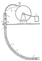
- the reference 1 indicates the reel on which is wound a rod 2 which is used for the movements of the instrument 3 in the well 4, so as to carry out the measurements or the interventions in one or more zones of the well 4.
- the rod 2 which is very flexible, leaves the reel 1 by passing over a deflection member 5, such as a set of pulleys, adapted to position the rod in the axis of the well whatever the position of the reel and its filling, and passes through means 6 of traction and thrust adapted to push the rod 2 into the well, to retain it or to extract it therefrom.
- a deflection member 5 such as a set of pulleys
- These traction and pushing means 6 can, for example, consist of two rubber tracks enclosing the rod 2 and moving in the desired direction to maneuver the rod 2.
- the rod 2 which is resistant to compression so as to allow a thrust on the instrument 3, is made of a very limited number of elements and may even have only one.
- the rod 2 comprises at least one line suitable for transferring energy or information, such as one (or more) electrical, fluidic or optical line, which makes it possible to connect the instrument 3 placed in the well at the lower end of the rod to the surface where the upper end of the rod is located 2. To this upper end are connected, optionally by means of a rotating connector, apparatus 7 for monitoring or controlling the instrument 3.
- a such rod can be made of composite material with glass, carbon, polyaramide reinforcing fibers embedded in a matrix of thermoplastic or thermosetting resin. This composite material may advantageously consist of glass fibers embedded in an epoxy resin.
- the nature of the matrix and of the fibers can be judiciously chosen to reduce friction and wear due to friction between the rod 2 and the wall of the well 4 during movements of the instrument 3.
- the line adapted to the transfer of energy and information is advantageously embedded in the rod 2 at the time of its manufacture.
- the rod 2 can also be made of a polymeric material resistant in particular to the mechanical stresses of use, and to the thermal and chemical stresses encountered in the well. It has been found that thermoplastic polymers of the polyamide, polyvinylidene fluoride or crosslinked high density polyethylene type make it possible to produce a flexible flexible rod which is resistant to corrosion according to the invention.
- Extrusion and pultrusion are called each of the processes by which a malleable material is respectively pushed by a press into a die or pulled at the outlet of a die.
- the rod 2 may be full (or massive). It can also be hollow and the transfer line can be embedded in this rod.
- the rod 2 may include means enabling it to resist torsional forces, such as a reinforcing braid disposed in the vicinity of the periphery of the rod.
- the upper part of the well 4 comprises means 21 for closing the well 4 and sealing with the rod 2 which make it possible to hold the instrument 3 in the well or to move the instrument 3 while it is connected to the soil surface by the rod 2.
- a conduit 22 then allowing the evacuation of the effluents produced.
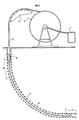
- the rod 2 (Fig. 2) is only disposed between the instrument 3 and a drill rod 8 adapted to compress the rod 2, so as to advance the instrument 3 into the well 4.
- the drill rod is connected to the ground surface by a flexible element 9 which can be a rod such as that connecting the drill rod 8 to the instrument 3, or else a cable provided with conductors, optical lines or fluidics.
- the flexible element 9 like the rod 2 are wound on the reel 1 and unwound from the reel via the return member 5, the mass-rod 8 being removed from the rod 2 and from the flexible element 9 for allow winding.
- the length of the rod 2 will be such that the distance D over which the mass-rod 9 can move is at least equal to the length L of the area to be explored.
- the operation of the instrument 3, or the information coming from it, is conveyed through the rod 2, the flexible element 9 and possibly the mass-rod 8, by the transfer lines or the conductors of those -this to the surface where the instruments 7 for monitoring and controlling the instrument 3 are located.
- the rod 2 is produced in a single section, for example 1000, 2000, 3000 meters, but it will not depart from the scope of the invention by using for this rod 2 a limited number of sections assembled together. following the others.
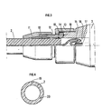
- Figure 3 shows in detail the mechanical connection between the lower end of the rod 2 and the instrument 3.
- the mechanical connection between the rod 2 and the instrument 3 which have respectively (for example) diameters of 25 millimeters and 75 millimeters, is in particular ensured by the anchoring of an olive 10 in the rod 2, the anchoring being carried out by a cooperation of the nuts 11 and 12 having conical bores which press the olive 10 onto the stem, this anchoring assembly 10, 11, 12 being fixed to the body of the instrument 3 by a collar nut 13 cooperating with a collar 14 integral with the anchoring assembly, in particular of the nut 12.
- the electrical connection of the transfer line 15 with the instrument 3 is carried out by a female plug 16 cooperating with a sealed electrical crossing of the instrument.
- a female plug and a bushing that can be used for this connection are for example available from the company DEUTSCH under the reference type 9701.
- the space 17 between the end of the rod 2 and the instrument 3 is filled with an insulating fluid, such as silicone grease, and is confined by means of sealing means, such as O-rings 18.
- an insulating fluid such as silicone grease
- the rod 2 is hollow and comprises one or more electrical conductors, or more generally at least one transfer line embedded in the thickness of the rod.
- This particular arrangement makes it possible in particular to increase the inertia in bending of the rod by optimizing the material used, to use the empty central part to dispose a fluid, and possibly to circulate a working fluid, such as mud from drilling.
- the transfer lines 19, 20 can be arranged symmetrically or asymmetrically in the rod 2.
Description
La présente invention concerne un dispositif, une application de ce dispositif et une méthode utilisant ce dispositif, permettant d'effectuer des mesures ou/et interventions dans un puits au niveau de formations environnantes.The present invention relates to a device, an application of this device and a method using this device, making it possible to carry out measurements or / and interventions in a well at the level of surrounding formations.
L'invention est notamment applicable lorsqu'il s'agit d'effectuer des mesures et/ou interventions au niveau de formations géologiques traversées par un puits. Dans ce cas, les mesures effectuées peuvent comporter l'enregistrement de la pression et de la température de fond du puits, la mesure (focalisée ou non) de la résistivité électrique des formations, ainsi que des mesures acoustiques, nucléaires, etc...The invention is particularly applicable when it is a question of carrying out measurements and / or interventions at the level of geological formations crossed by a well. In this case, the measurements carried out may include the recording of the pressure and the bottom temperature of the well, the measurement (focused or not) of the electrical resistivity of the formations, as well as acoustic, nuclear, etc. measurements.
Ces techniques de mesure ou d'intervention sont bien connues des spécialistes et ne seront pas décrites ici plus en détail.These measurement or intervention techniques are well known to specialists and will not be described here in more detail.
La présente invention est particulièrement bien adaptée pour effectuer des mesures ou des interventions dans un puits de production d'effluents pétrolier. Ce puits pourra comporter de préférence des tubes ou drains qui en délimitent les parois.The present invention is particularly well suited for carrying out measurements or interventions in a petroleum effluent production well. This well may preferably include tubes or drains which delimit the walls thereof.
Le brevet EP-A-0/256.601 décrit par exemple une méthode et un dispositif pour forer dans le sol à l'aide d'un ensemble comportant deux tubes concentriques en métal ou en matériau de synthèse, rigide et débobiné d'un touret par déformation plastique du matériau des tubes.Patent EP-A-0 / 256,601 describes for example a method and a device for drilling in the ground using an assembly comprising two concentric tubes of metal or of synthetic material, rigid and unwound from a reel by plastic deformation of the tube material.
On connait le brevet US-4.685.816 qui décrit un dispositif de mesure ou d'intervention dans un puits, comportant un instrument disposé à la partie inférieure d'un tube creux initialement enroulé sur un touret que l'on fait tourner pour déplacer l'instrument dans un puits.The patent US Pat. No. 4,685,816 is known which describes a device for measuring or intervening in a well, comprising an instrument disposed at the bottom of a hollow tube initially wound on a reel which is rotated to move the instrument in a well.
Les tubes décrits dans ces deux documents, qui sont en métal, possèdent une faible flexibilité pour faciliter le mouvement de l'instrument. Cette flexibilité produit des déformations plastiques lors de son enroulement sur le touret, ou de son déroulement du touret. Le conducteur électrique qu'ils peuvent contenir sont disposés dans l'espace creux du tube. La mise en place d'un tel conducteur pose un problème, car elle ne peut être effectuée alors que le tube est enroulé. Ce tube est de plus relativement lourd.The tubes described in these two documents, which are made of metal, have little flexibility to facilitate the movement of the instrument. This flexibility produces plastic deformations during its winding on the drum, or during its unwinding of the drum. The electrical conductor which they can contain is arranged in the hollow space of the tube. The installation of such a conductor poses a problem, because it cannot be carried out while the tube is wound. This tube is also relatively heavy.
Le brevet FR-B-1.249.236 décrit un tube flexible en acier utilisable pour forer le sol. Ce tube est très coûteux à fabriquer.Patent FR-B-1,249,236 describes a flexible steel tube usable for drilling the ground. This tube is very expensive to manufacture.
Tous les tubes traditionnellement utilisés craignent la corrosion et ne sont pas particulièrement adapté à réduire les frottements avec la paroi du puits au cours du déplacement de l'instrument, ni même à résister à ces frottements.All traditionally used tubes fear corrosion and are not particularly suitable for reducing friction with the wall of the well during the movement of the instrument, or even for resisting this friction.
Les inconvénients des dispositifs selon l'art antérieur sont considérablement réduits, si ce n'est éliminés, par l'utilisation du dispositif selon la présente invention pour effectuer des mesures ou des interventions dans un puits foré, ce dispositif comportant une tige, ou jonc, reliée à un instrument de mesure ou d'intervention, ledit instrument étant disposé à une extrémité inférieure de la tige.The drawbacks of the devices according to the prior art are considerably reduced, if not eliminated, by the use of the device according to the present invention for carrying out measurements or interventions in a drilled well, this device comprising a rod, or rod , connected to a measuring or intervention instrument, said instrument being disposed at a lower end of the rod.
Selon ce dispositif, la tige est notamment élastique en flexion et rigide en compression, cette tige comportant au moins une ligne adaptée au transfert d'énergie ou d'informations, telle qu'une ligne électrique, fluidique, ou optique, la ligne étant noyée dans la tige, et la tige est adaptée à être enroulée sur au moins un touret et comporte un matériau composite ou un matériau polymérique non composite.According to this device, the rod is in particular elastic in bending and rigid in compression, this rod comprising at least one line suitable for the transfer of energy or information, such as an electrical, fluidic, or optical line, the line being embedded in the rod, and the rod is adapted to be wound on at least one reel and comprises a composite material or a non-composite polymeric material.
Le matériau composite pourra être constitué, par exemple, de fibres de verre, de carbone ou de polyaramide, tel du Kevlar qui est une marque déposée par Dupont de Nemours, ces fibres étant noyées dans une matrice en résine thermoplastique ou thermodurcissable.The composite material may consist, for example, of glass, carbon or polyaramide fibers, such as Kevlar which is a trademark registered by Dupont de Nemours, these fibers being embedded in a matrix of thermoplastic or thermosetting resin.
Le matériau polymérique dépourvu d'éléments de renfort, pourra être choisi parmi les éléments du groupe des polymères suivants : polyamide, polyfluorure de vinylidène, polyéthylène haute densité réticulé.The polymeric material devoid of reinforcing elements may be chosen from elements from the group of the following polymers: polyamide, polyvinylidene fluoride, crosslinked high density polyethylene.
La tige pourra être sensiblement pleine. Lorsque la tige comporte une fibre neutre le long de laquelle aucune contrainte de traction ou de compression n'apparaît lorsque l'on soumet ladite tige à une flexion, la ligne de transfert pourra être sensiblement disposée au voisinage de la fibre neutre. La tige pourra être adaptée à résister à la torsion.The rod may be substantially full. When the rod has a neutral fiber along which no tensile or compressive stress appears when the rod is subjected to bending, the transfer line may be substantially disposed in the vicinity of the neutral fiber. The rod can be adapted to resist twisting.
La nature du matériau constituant la partie extérieure de la tige pourra être adaptée à diminuer le frottement entre la tige et la paroi du puits.The nature of the material constituting the external part of the rod may be adapted to reduce the friction between the rod and the wall of the well.
La tige pourra être fabriquée par une machine produisant en continu, notamment par extrusion ou par pultrusion.The rod may be manufactured by a machine producing continuously, in particular by extrusion or by pultrusion.
La tige pourra comporter plusieurs lignes de transfert d'énergie ou d'informations.The rod may include several lines of energy or information transfer.
La tige pourra être creuse et la ligne pourra être noyée dans l'épaisseur de ladite tige. La partie extérieure de la tige pourra comporter un agent antiabrasion.The rod may be hollow and the line may be embedded in the thickness of said rod. The outer part of the rod may include an anti-abrasion agent.
L'invention sera bien comprise et ses avantages apparaîtront clairement à la lecture de la description suivante d'un exemple de réalisation illustré par les figures annexées dans lesquelles :
- la figure 1 représente un dispositif selon l'invention lors de sa mise en place dans le puits,
- la figure 2 illustre une variante du dispositif selon l'invention représentée à la figure 1,
- la figure 3, montre en détail la liaison entre l'extrémité inférieure de la tige et l'instrument permettant les mesures ou les interventions, et
- la figure 4, montre en coupe une tige creuse selon l'invention comportant des lignes de transfert.
- FIG. 1 represents a device according to the invention when it is placed in the well,
- FIG. 2 illustrates a variant of the device according to the invention shown in FIG. 1,
- FIG. 3 shows in detail the connection between the lower end of the rod and the instrument allowing the measurements or the interventions, and
- Figure 4 shows in section a hollow rod according to the invention comprising transfer lines.
Sur la figure 1, la référence 1 indique le touret sur lequel est bobinée une tige 2 qui sert aux déplacements de l'instrument 3 dans le puits 4, de manière à effectuer les mesures ou les interventions dans une ou plusieurs zones du puits 4.In FIG. 1, the
La tige 2, qui est très flexible, quitte le touret 1 en passant sur un organe de renvoi 5, tel un ensemble de poulies, adapté à positionner la tige dans l'axe du puits quelle que soit la position du touret et son remplissage, et traverse des moyens 6 de traction et de poussée adaptés à pousser la tige 2 dans le puits, à la retenir ou à l'en extraire.The
Ces moyens 6 de traction et de poussée peuvent, par exemple, être constitués de deux chenilles en caoutchouc enserrant la tige 2 et se déplaçant dans le sens souhaité pour manoeuvrer la tige 2.These traction and pushing means 6 can, for example, consist of two rubber tracks enclosing the
La tige 2, qui est résistante à la compression de manière à permettre une poussée sur l'instrument 3, est réalisée en un nombre très limité d'éléments et peut même n'en comporter qu'un seul.The
La tige 2 comporte au moins une ligne adaptée en transfert d'énergie ou d'informations, telle une (ou plusieurs) ligne électrique, fluidique ou optique, qui permet de relier l'instrument 3 disposé dans le puits à l'extrémité inférieure de la tige à la surface où se trouve l'extrémité supérieure de la tige 2. A cette extrémité supérieure sont reliés, éventuellement par l'intermédiaire d'un connecteur tournant, des appareils 7 de contrôle ou de commande de l'instrument 3. Une telle tige peut être réalisée en matériau composite avec des fibres de renfort en verre, en carbone, en polyaramide noyées dans une matrice en résine thermoplastique ou thermodurcissable. Ce matériau composite pourra avantageusement être constitué de fibres de verre noyées dans une résine époxyde.The
La nature de la matrice et des fibres peut être judicieusement choisie pour diminuer les frottements et l'usure due aux frottements entre la tige 2 et la paroi du puits 4 au cours des déplacements de l'instrument 3.The nature of the matrix and of the fibers can be judiciously chosen to reduce friction and wear due to friction between the
La ligne adaptée au transfert d'énergie et d'informations est avantageusement noyée dans la tige 2 au moment de sa fabrication.The line adapted to the transfer of energy and information is advantageously embedded in the
La tige 2 peut aussi être réalisée dans un matériau polymérique résistant notamment aux contraintes mécaniques d'utilisation, et aux contraintes thermiques et chimiques rencontrées dans le puits. On a trouvé que le polymères thermoplastiques du type polyamide, polyfluorure de vinylidène ou polyéthylène haute densité réticulé permettent la réalisation d'une tige flexible légère et résistante à la corrosion selon l'invention.The
Pour réaliser la tige 2, on pourra utiliser une machine de fabrication en continu et d'un type permettant de noyer la ou les lignes de transfert dans la tige. On pourra utiliser les techniques dites d'extrusion ou de pultrusion.To make the
On appelle extrusion et pultrusion chacun des procédés par lequel une matière malléable est respectivement poussée par une presse dans une filière ou tirée à la sortie d'une filière. La tige 2 pourra être pleine (ou massive). Elle pourra aussi être creuse et la ligne de transfert pourra être noyée dans cette tige.Extrusion and pultrusion are called each of the processes by which a malleable material is respectively pushed by a press into a die or pulled at the outlet of a die. The
On pourra avantageusement ajouter au matériau composite ou polymérique constituant ladite tige 2 des agents antiabrasion destinés à réduire l'usure de ladite tige 2 et/ou de la paroi du puits.It will advantageously be possible to add to the composite or polymeric material constituting said
La tige 2 pourra comporter des moyens lui permettant de résister aux efforts de torsion, telle une tresse de renfort disposée au voisinage de la périphérie de la tige.The
La partie supérieure du puits 4 comporte des moyens d'obturation 21 du puits 4 et d'étanchéité avec la tige 2 qui permettent de maintenir l'instrument 3 dans le puits ou de déplacer l'instrument 3 alors qu'il est relié à la surface du sol par la tige 2. Une telle disposition se rencontre lorsque le puits est en production, un conduit 22 permettant alors l'évacuation des effluents produits.The upper part of the well 4 comprises means 21 for closing the well 4 and sealing with the
Selon une variante illustrée à la figure 2 du dispositif de la figure 1, sur laquelle la tige 2 relie l'instrument 3 au touret 1 disposé en surface, la tige 2 (Fig. 2) est seulement disposée entre l'instrument 3 et une masse-tige 8 adaptée à mettre en compression la tige 2, de façon à faire avancer l'instrument 3 dans le puits 4. La masse-tige est reliée à la surface du sol par un élément flexible 9 qui peut être une tige telle que celle reliant la masse-tige 8 à l'instrument 3, ou encore un câble pourvu de conducteurs, de lignes optiques ou fluidiques.According to a variant illustrated in FIG. 2 of the device of FIG. 1, on which the
De cette manière, en service normal, seule la tige 2 disposée entre la masse-tige 8 et l'instrument 3 est soumise à une compression, alors que l'élément flexible 9 n'est soumis qu'à une traction.In this way, in normal service, only the
Ceci permet notamment de réduire les dimensions transversales de l'élément flexible 9 et ainsi le coût du dispositif de mesure ou d'intervention.This makes it possible in particular to reduce the transverse dimensions of the flexible element 9 and thus the cost of the measurement or intervention device.
L'élément flexible 9 comme la tige 2 sont enroulés sur le touret 1 et déroulés du touret par l'intermédiaire de l'organe de renvoi 5, la masse-tige 8 étant ôtée de la tige 2 et de l'élément flexible 9 pour permettre l'enroulement. On pourra également utiliser une masse-tige 8 adaptée à être enroulée sur le touret 1.The flexible element 9 like the
Adaptée aux mesures et interventions dans les puits fortement déviés, voire horizontaux, la longueur de la tige 2 sera telle que la distance D sur laquelle peut se déplacer la masse-tige 9 est au moins égale à la longueur L de la zone à explorer.Adapted to measurements and interventions in wells deviated, even horizontal, the length of the
La manoeuvre de l'instrument 3, ou les informations provenant de celui-ci, sont véhiculés au travers de la tige 2, de l'élément flexible 9 et éventuellement la masse-tige 8, par les lignes de transfert ou les conducteurs de ceux-ci jusqu'à la surface où se trouvent les appareils 7 de contrôle et de commande de l'instrument 3.The operation of the
D'une manière avantageuse, la tige 2 est réalisée en un seul tronçon, par exemple 1000, 2000, 3000 mètres, mais on ne sortira pas du cadre de l'invention en utilisant pour cette tige 2 un nombre restreint de tronçons assemblés les uns à la suite des autres.Advantageously, the
La figure 3 montre en détail la liaison mécanique entre l'extrémité inférieure de la tige 2 et l'instrument 3. La liaison mécanique entre la tige 2 et l'instrument 3 qui ont respectivement (par exemple) des diamètres de 25 millimètres et 75 millimètres, est notamment assurée par l'ancrage d'une olive 10 dans la tige 2, l'ancrage étant réalisé par une coopération des écrous 11 et 12 ayant des alésages coniques qui pressent l'olive 10 sur la tige, cet ensemble d'ancrage 10, 11, 12 étant fixé au corps de l'instrument 3 par un écrou 13 de collet coopérant avec un collet 14 solidaire de l'ensemble d'ancrage, notamment de l'écrou 12.Figure 3 shows in detail the mechanical connection between the lower end of the
La liaison électrique de la ligne de transfert 15 avec l'instrument 3 est effectuée par une fiche femelle 16 coopérant avec une traversée électrique étanche de l'instrument.The electrical connection of the
Une fiche femelle et une traversée utilisables pour cette liaison sont par exemple disponibles chez la société DEUTSCH sous la référence type 9701.A female plug and a bushing that can be used for this connection are for example available from the company DEUTSCH under the reference type 9701.
De manière à notamment éviter les pertes électriques à la connexion, l'espace 17 entre l'extrémité de la tige 2 et l'instrument 3 est rempli d'un fluide isolant, tel de la graisse de silicone, et est confiné grâce à des moyens d'étanchéité, tels les joints toriques 18.In order to in particular avoid electrical losses on connection, the
Sur la figure 4, qui montre en coupe une variante de la tige selon l'invention, la tige 2 est creuse et comporte un ou plusieurs conducteurs électriques, ou plus généralement au moins une ligne de transfert noyée dans l'épaisseur de la tige. Cette disposition particulière permet notamment d'augmenter l'inertie en flexion de la tige en optimisant la matière utilisée, de se servir de la partie centrale vide pour disposer un fluide, et éventuellement pour faire circuler un fluide de travail, tel de la boue de forage. Les lignes de transfert 19, 20 peuvent être disposées symétriquement ou asymétriquement dans la tige 2.In Figure 4, which shows in section a variant of the rod according to the invention, the
Claims (14)
Applications Claiming Priority (2)
| Application Number | Priority Date | Filing Date | Title |
|---|---|---|---|
| FR8806828A FR2631708B1 (en) | 1988-05-20 | 1988-05-20 | DEVICE FOR PERFORMING MEASUREMENTS OR INTERVENTIONS IN A WELL, METHOD USING THE DEVICE AND APPLICATIONS OF THE DEVICE |
| FR8806828 | 1988-05-20 |
Publications (2)
| Publication Number | Publication Date |
|---|---|
| EP0352148A1 EP0352148A1 (en) | 1990-01-24 |
| EP0352148B1 true EP0352148B1 (en) | 1992-07-15 |
Family
ID=9366509
Family Applications (1)
| Application Number | Title | Priority Date | Filing Date |
|---|---|---|---|
| EP89401353A Expired - Lifetime EP0352148B1 (en) | 1988-05-20 | 1989-05-16 | Device and method for performing measurements or interventions in a borehole |
Country Status (7)
| Country | Link |
|---|---|
| US (1) | US5184682A (en) |
| EP (1) | EP0352148B1 (en) |
| BR (1) | BR8902356A (en) |
| CA (1) | CA1336261C (en) |
| DE (1) | DE68902106T2 (en) |
| FR (1) | FR2631708B1 (en) |
| NO (1) | NO174978C (en) |
Cited By (15)
| Publication number | Priority date | Publication date | Assignee | Title |
|---|---|---|---|---|
| WO1991019884A1 (en) * | 1990-06-15 | 1991-12-26 | Westech Geophysical, Inc. | Video logging system having remote power source |
| US5202944A (en) * | 1990-06-15 | 1993-04-13 | Westech Geophysical, Inc. | Communication and power cable |
| GB2261451A (en) * | 1991-11-13 | 1993-05-19 | Inst Francais Du Petrole | Logging and/or servicing wells |
| FR2769664A1 (en) | 1997-10-13 | 1999-04-16 | Inst Francais Du Petrole | MEASUREMENT METHOD AND SYSTEM HAVING SEMI-RIGID EXTENSION |
| FR2769665A1 (en) | 1997-10-13 | 1999-04-16 | Inst Francais Du Petrole | MEASUREMENT METHOD AND SYSTEM IN A HORIZONTAL DUCT |
| US5921285A (en) * | 1995-09-28 | 1999-07-13 | Fiberspar Spoolable Products, Inc. | Composite spoolable tube |
| US6016845A (en) * | 1995-09-28 | 2000-01-25 | Fiber Spar And Tube Corporation | Composite spoolable tube |
| US6157761A (en) * | 1997-10-13 | 2000-12-05 | Institut Francais Du Petrole | Reinforced composite rod |
| US6663453B2 (en) | 2001-04-27 | 2003-12-16 | Fiberspar Corporation | Buoyancy control systems for tubes |
| US6706348B2 (en) | 1997-10-10 | 2004-03-16 | Fiberspar Corporation | Composite spoolable tube with sensor |
| US8678041B2 (en) | 2004-02-27 | 2014-03-25 | Fiberspar Corporation | Fiber reinforced spoolable pipe |
| US8955599B2 (en) | 2009-12-15 | 2015-02-17 | Fiberspar Corporation | System and methods for removing fluids from a subterranean well |
| US8985154B2 (en) | 2007-10-23 | 2015-03-24 | Fiberspar Corporation | Heated pipe and methods of transporting viscous fluid |
| US9127546B2 (en) | 2009-01-23 | 2015-09-08 | Fiberspar Coproation | Downhole fluid separation |
| US9206676B2 (en) | 2009-12-15 | 2015-12-08 | Fiberspar Corporation | System and methods for removing fluids from a subterranean well |
Families Citing this family (40)
| Publication number | Priority date | Publication date | Assignee | Title |
|---|---|---|---|---|
| FR2658558B1 (en) * | 1990-02-22 | 1992-06-12 | Ungemach Pierre | WELL PROTECTION DEVICE AGAINST THE RISK OF CORROSION OR DEPOSITS DUE TO THE NATURE OF THE FLUID PRODUCED OR IN PLACE IN THE WELL. |
| FR2691203A1 (en) * | 1992-05-15 | 1993-11-19 | Mr Ind | Deep drilling auxiliary tube - has jointless core tube of fluoro resin covered by spirally-wound metal cables including a conductor to detect damage |
| FR2708055B1 (en) * | 1993-07-19 | 1995-08-25 | Inst Francais Du Petrole | Connection device for composite rod. |
| GB2283035B (en) * | 1993-10-25 | 1997-08-06 | Camco Int | Coiled tubing with signal transmitting passageway |
| FR2711728B1 (en) * | 1993-10-25 | 1998-03-27 | Camco Int | Coiled tubing with a signal transmission passage. |
| FR2712628B1 (en) * | 1993-11-15 | 1996-01-12 | Inst Francais Du Petrole | Measuring device and method in a hydrocarbon production well. |
| FR2712627B1 (en) * | 1993-11-17 | 1996-01-05 | Schlumberger Services Petrol | Method and device for monitoring and / or studying a hydrocarbon reservoir crossed by a well. |
| CA2233345C (en) * | 1995-09-28 | 2004-12-14 | Fiber Spar And Tube Corporation | Composite coiled tubing end connector |
| US7498509B2 (en) * | 1995-09-28 | 2009-03-03 | Fiberspar Corporation | Composite coiled tubing end connector |
| US8678042B2 (en) | 1995-09-28 | 2014-03-25 | Fiberspar Corporation | Composite spoolable tube |
| FR2745847B1 (en) * | 1996-03-08 | 2000-09-15 | Inst Francais Du Petrole | MEASUREMENT TRANSMISSION SYSTEM COMPRISING AN OPTOELECTRIC CONVERTER |
| AU2759699A (en) * | 1998-02-17 | 1999-08-30 | Vibration Technology Llc | Downhole coiled tubing recovery apparatus |
| US6264244B1 (en) | 1998-04-29 | 2001-07-24 | Halliburton Energy Services, Inc. | End connector for composite coiled tubing |
| US7185700B2 (en) * | 2004-06-14 | 2007-03-06 | Weatherford/Lamb, Inc. | Separable plug for use with a wellbore tool |
| US6915849B2 (en) | 2001-04-23 | 2005-07-12 | Weatherford/Lamb, Inc. | Apparatus and methods for conveying instrumentation within a borehole using continuous sucker rod |
| US7513305B2 (en) * | 1999-01-04 | 2009-04-07 | Weatherford/Lamb, Inc. | Apparatus and methods for operating a tool in a wellbore |
| US7407006B2 (en) * | 1999-01-04 | 2008-08-05 | Weatherford/Lamb, Inc. | System for logging formations surrounding a wellbore |
| US6148925A (en) * | 1999-02-12 | 2000-11-21 | Moore; Boyd B. | Method of making a conductive downhole wire line system |
| US6321596B1 (en) | 1999-04-21 | 2001-11-27 | Ctes L.C. | System and method for measuring and controlling rotation of coiled tubing |
| CA2857859A1 (en) | 1999-10-01 | 2001-04-12 | Fiberspar Corporation | Composite coiled tubing end connector and pipe-to-pipe connector |
| US6464014B1 (en) | 2000-05-23 | 2002-10-15 | Henry A. Bernat | Downhole coiled tubing recovery apparatus |
| US6443242B1 (en) | 2000-09-29 | 2002-09-03 | Ctes, L.C. | Method for wellbore operations using calculated wellbore parameters in real time |
| EP1366270B1 (en) * | 2001-03-09 | 2019-09-04 | Schlumberger Holdings Limited | Logging system for use in a wellbore |
| US6557630B2 (en) | 2001-08-29 | 2003-05-06 | Sensor Highway Limited | Method and apparatus for determining the temperature of subterranean wells using fiber optic cable |
| GB2397859B (en) * | 2001-11-05 | 2006-02-22 | Fiberspar Corp | Spoolable composite tubing with a catalytically cured matrix |
| WO2003083338A1 (en) | 2002-03-29 | 2003-10-09 | Fiberspar Corporation | Systems and methods for pipeline rehabilitation |
| AU2003267553A1 (en) * | 2002-08-30 | 2004-03-19 | Sensor Highway Limited | Method and apparatus for logging a well using fiber optics |
| US7350569B2 (en) * | 2004-06-14 | 2008-04-01 | Weatherford/Lamb, Inc. | Separable plug for use in a wellbore |
| GB0415223D0 (en) | 2004-07-07 | 2004-08-11 | Sensornet Ltd | Intervention rod |
| US8187687B2 (en) * | 2006-03-21 | 2012-05-29 | Fiberspar Corporation | Reinforcing matrix for spoolable pipe |
| US8839822B2 (en) * | 2006-03-22 | 2014-09-23 | National Oilwell Varco, L.P. | Dual containment systems, methods and kits |
| US8671992B2 (en) * | 2007-02-02 | 2014-03-18 | Fiberspar Corporation | Multi-cell spoolable composite pipe |
| US8746289B2 (en) | 2007-02-15 | 2014-06-10 | Fiberspar Corporation | Weighted spoolable pipe |
| AU2008265962B2 (en) | 2007-06-15 | 2011-12-15 | Weatherford Technology Holdings, Llc | Control line running system |
| US20100108323A1 (en) * | 2008-10-31 | 2010-05-06 | Weatherford/Lamb, Inc. | Reliable Sleeve Activation for Multi-Zone Frac Operations Using Continuous Rod and Shifting Tools |
| WO2010132685A1 (en) * | 2009-05-14 | 2010-11-18 | Fiberod, Inc. | Spooling arrangement for continuous composite sucker rod |
| US20110210542A1 (en) * | 2010-02-23 | 2011-09-01 | Makselon Christopher E | Connector for Spoolable Pipe |
| WO2014026190A1 (en) | 2012-08-10 | 2014-02-13 | National Oilwell Varco, L.P. | Composite coiled tubing connectors |
| FR3017155B1 (en) * | 2014-02-05 | 2016-02-26 | Total Sa | METHOD FOR MONITORING AN INTERVENTION IN A FLUID OPERATING WELL IN THE BASEMENT, AND ASSOCIATED INTERVENTION DEVICE |
| CN114382458B (en) * | 2021-12-15 | 2023-06-27 | 中建三局集团有限公司 | Visual real-time monitoring method for underground water level and stratum deformation in underground construction process |
Family Cites Families (11)
| Publication number | Priority date | Publication date | Assignee | Title |
|---|---|---|---|---|
| FR1249236A (en) * | 1958-11-27 | 1960-12-30 | Inst Francais Du Petrole | New drilling method |
| DE2026474A1 (en) * | 1970-05-29 | 1972-02-03 | Mancar-Trust, Vaduz | Deep drilling rig |
| US4024913A (en) * | 1974-03-25 | 1977-05-24 | Grable Donovan B | Well installations employing non-metallic lines, tubing casing and machinery |
| FR2423707A1 (en) * | 1978-04-17 | 1979-11-16 | Coflexip | FLEXIBLE TUBULAR DUCT |
| US4452314A (en) * | 1982-04-19 | 1984-06-05 | Owens-Corning Fiberglas Corporation | Method of installing a reinforced thermosetting resin sucker rod assembly composed of pultruded arcuate sections |
| US4585066A (en) * | 1984-11-30 | 1986-04-29 | Shell Oil Company | Well treating process for installing a cable bundle containing strands of changing diameter |
| FR2575515B1 (en) * | 1984-12-28 | 1988-11-10 | Inst Francais Du Petrole | HYDRAULIC PRESSURE DEVICE ALLOWING MEASUREMENTS AND INTERVENTIONS DURING INJECTION OR PRODUCTION IN A DEVIED WELL |
| FR2592655B1 (en) * | 1986-01-07 | 1988-07-29 | Atochem | COMPOSITE BASED ON VINYLIDENE POLYFLUORIDE WITH IMPROVED HOLD IN CONTACT WITH HYDROCARBONS - APPLICATION TO THE MANUFACTURE OF TUBE FOR THE OIL INDUSTRY. |
| US4685516A (en) * | 1986-01-21 | 1987-08-11 | Atlantic Richfield Company | Apparatus for operating wireline tools in wellbores |
| US4681169A (en) * | 1986-07-02 | 1987-07-21 | Trw, Inc. | Apparatus and method for supplying electric power to cable suspended submergible pumps |
| BE905265A (en) * | 1986-08-13 | 1986-12-01 | Smet Nik | METHOD AND APPARATUS FOR MAKING A HOLE IN THE GROUND. |
-
1988
- 1988-05-20 FR FR8806828A patent/FR2631708B1/en not_active Expired - Lifetime
-
1989
- 1989-05-16 DE DE8989401353T patent/DE68902106T2/en not_active Expired - Fee Related
- 1989-05-16 EP EP89401353A patent/EP0352148B1/en not_active Expired - Lifetime
- 1989-05-18 NO NO891988A patent/NO174978C/en not_active IP Right Cessation
- 1989-05-19 BR BR898902356A patent/BR8902356A/en not_active IP Right Cessation
- 1989-05-19 CA CA000600242A patent/CA1336261C/en not_active Expired - Lifetime
- 1989-05-22 US US07/354,876 patent/US5184682A/en not_active Expired - Lifetime
Cited By (26)
| Publication number | Priority date | Publication date | Assignee | Title |
|---|---|---|---|---|
| WO1991019884A1 (en) * | 1990-06-15 | 1991-12-26 | Westech Geophysical, Inc. | Video logging system having remote power source |
| US5140319A (en) * | 1990-06-15 | 1992-08-18 | Westech Geophysical, Inc. | Video logging system having remote power source |
| US5202944A (en) * | 1990-06-15 | 1993-04-13 | Westech Geophysical, Inc. | Communication and power cable |
| US5355128A (en) * | 1990-06-15 | 1994-10-11 | Westech Geophysical, Inc. | Video logging system having an optical communications link |
| EP0643198A2 (en) * | 1990-06-15 | 1995-03-15 | Westech Geophysical, Inc. | Video logging system having remote power source |
| GB2261451A (en) * | 1991-11-13 | 1993-05-19 | Inst Francais Du Petrole | Logging and/or servicing wells |
| GB2261451B (en) * | 1991-11-13 | 1995-09-06 | Inst Francais Du Petrole | Device for taking measurements and carrying out servicing in a well and its application in an oil well |
| US6148866A (en) * | 1995-09-28 | 2000-11-21 | Fiberspar Spoolable Products, Inc. | Composite spoolable tube |
| US5921285A (en) * | 1995-09-28 | 1999-07-13 | Fiberspar Spoolable Products, Inc. | Composite spoolable tube |
| US6016845A (en) * | 1995-09-28 | 2000-01-25 | Fiber Spar And Tube Corporation | Composite spoolable tube |
| US6357485B2 (en) | 1995-09-28 | 2002-03-19 | Fiberspar Corporation | Composite spoolable tube |
| US6286558B1 (en) * | 1995-09-28 | 2001-09-11 | Fiberspar Corporation | Composite spoolable tube |
| GB2338736B (en) * | 1997-02-24 | 2001-06-13 | Fiberspar Spoolable Prod Inc | Composite spoolable tube |
| GB2338736A (en) * | 1997-02-24 | 1999-12-29 | Fiberspar Spoolable Prod Inc | Composite spoolable tube |
| US6706348B2 (en) | 1997-10-10 | 2004-03-16 | Fiberspar Corporation | Composite spoolable tube with sensor |
| US6179058B1 (en) | 1997-10-13 | 2001-01-30 | Institut Francis Du Petrole | Measuring method and system comprising a semi-rigid extension |
| US6173787B1 (en) | 1997-10-13 | 2001-01-16 | Institut Francais Du Petrole | Method and system intended for measurements in a horizontal pipe |
| US6157761A (en) * | 1997-10-13 | 2000-12-05 | Institut Francais Du Petrole | Reinforced composite rod |
| FR2769664A1 (en) | 1997-10-13 | 1999-04-16 | Inst Francais Du Petrole | MEASUREMENT METHOD AND SYSTEM HAVING SEMI-RIGID EXTENSION |
| FR2769665A1 (en) | 1997-10-13 | 1999-04-16 | Inst Francais Du Petrole | MEASUREMENT METHOD AND SYSTEM IN A HORIZONTAL DUCT |
| US6663453B2 (en) | 2001-04-27 | 2003-12-16 | Fiberspar Corporation | Buoyancy control systems for tubes |
| US8678041B2 (en) | 2004-02-27 | 2014-03-25 | Fiberspar Corporation | Fiber reinforced spoolable pipe |
| US8985154B2 (en) | 2007-10-23 | 2015-03-24 | Fiberspar Corporation | Heated pipe and methods of transporting viscous fluid |
| US9127546B2 (en) | 2009-01-23 | 2015-09-08 | Fiberspar Coproation | Downhole fluid separation |
| US8955599B2 (en) | 2009-12-15 | 2015-02-17 | Fiberspar Corporation | System and methods for removing fluids from a subterranean well |
| US9206676B2 (en) | 2009-12-15 | 2015-12-08 | Fiberspar Corporation | System and methods for removing fluids from a subterranean well |
Also Published As
| Publication number | Publication date |
|---|---|
| DE68902106T2 (en) | 1992-12-10 |
| DE68902106D1 (en) | 1992-08-20 |
| FR2631708B1 (en) | 1990-09-28 |
| NO174978B (en) | 1994-05-02 |
| EP0352148A1 (en) | 1990-01-24 |
| NO891988L (en) | 1989-11-21 |
| FR2631708A1 (en) | 1989-11-24 |
| BR8902356A (en) | 1990-01-09 |
| NO891988D0 (en) | 1989-05-18 |
| CA1336261C (en) | 1995-07-11 |
| US5184682A (en) | 1993-02-09 |
| NO174978C (en) | 1994-08-10 |
Similar Documents
| Publication | Publication Date | Title |
|---|---|---|
| EP0352148B1 (en) | Device and method for performing measurements or interventions in a borehole | |
| EP0542584B1 (en) | Flexible tubing containing a centred line for transfer of energy or information and method of manufacturing such tubing | |
| CA2247310C (en) | Method and system of measurement in a horizontal pipe | |
| US8985154B2 (en) | Heated pipe and methods of transporting viscous fluid | |
| US6361299B1 (en) | Composite spoolable tube with sensor | |
| US7024941B2 (en) | Method of mounting a sensor arrangement in a tubular member, and use of the method | |
| EP2795281B1 (en) | Method for monitoring the integrity of a flexible line extending through a fluid exploitation facility, and associated flexible line, kit and production process | |
| EP3024641B1 (en) | Method and facility for producing an instrumented pipe | |
| WO1997020162A1 (en) | Multiple-tube flexible pipe having high compressive strength | |
| FR2712628A1 (en) | Device and method of measurement in a hydrocarbon production well. | |
| FR2849929A1 (en) | Telecommunication optical fiber cable, has external layer surrounding maintenance sheath of low thickness, where external layer comprises lower coefficient of friction and higher stiffness than maintenance sheath | |
| FR2996280A1 (en) | FLEXIBLE TUBULAR DRIVEN INSTRUMENTEE | |
| WO2001035011A1 (en) | Clamp system for maintaining a duct tensioned and floating support comprising same | |
| EP3529577B1 (en) | Method for monitoring the upthrust of a subsea pipeline buoy | |
| FR2683591A1 (en) | DEVICE FOR MEASUREMENT AND INTERVENTION IN DRILLING AND USE IN A PETROLEUM WELL. | |
| FR2769749A1 (en) | REINFORCED ROD IN COMPOSITE MATERIAL | |
| AU756204B2 (en) | Enhancement of profiled tubular lining systems by channel augmentation | |
| FR2767861A1 (en) | COMBINATION FIBER OPTICAL AND ELECTRICALLY CONDUCTIVE LOGGING CABLE | |
| FR2691203A1 (en) | Deep drilling auxiliary tube - has jointless core tube of fluoro resin covered by spirally-wound metal cables including a conductor to detect damage | |
| FR2791768A1 (en) | Bragg network extensometer for monitoring works of art, comprises optical fibre which has Bragg networks inscibed within and is covered by a reinforced plastic core also measuring equipment | |
| Fernandez et al. | Pipeline hydrocarbon transportation: some operating concerns and R&D trends | |
| CA2561402C (en) | Composite spoolable tube with sensor | |
| FR2678703A1 (en) | Method for manufacturing a line of variable stiffness and associated element |
Legal Events
| Date | Code | Title | Description |
|---|---|---|---|
| PUAI | Public reference made under article 153(3) epc to a published international application that has entered the european phase |
Free format text: ORIGINAL CODE: 0009012 |
|
| 17P | Request for examination filed |
Effective date: 19890527 |
|
| AK | Designated contracting states |
Kind code of ref document: A1 Designated state(s): DE GB IT NL |
|
| 17Q | First examination report despatched |
Effective date: 19910307 |
|
| ITF | It: translation for a ep patent filed |
Owner name: DE DOMINICIS & MAYER S.R.L. |
|
| GRAA | (expected) grant |
Free format text: ORIGINAL CODE: 0009210 |
|
| AK | Designated contracting states |
Kind code of ref document: B1 Designated state(s): DE GB IT NL |
|
| REF | Corresponds to: |
Ref document number: 68902106 Country of ref document: DE Date of ref document: 19920820 |
|
| GBT | Gb: translation of ep patent filed (gb section 77(6)(a)/1977) | ||
| PLBE | No opposition filed within time limit |
Free format text: ORIGINAL CODE: 0009261 |
|
| STAA | Information on the status of an ep patent application or granted ep patent |
Free format text: STATUS: NO OPPOSITION FILED WITHIN TIME LIMIT |
|
| 26N | No opposition filed | ||
| REG | Reference to a national code |
Ref country code: GB Ref legal event code: IF02 |
|
| PGFP | Annual fee paid to national office [announced via postgrant information from national office to epo] |
Ref country code: NL Payment date: 20070529 Year of fee payment: 19 |
|
| PGFP | Annual fee paid to national office [announced via postgrant information from national office to epo] |
Ref country code: DE Payment date: 20070604 Year of fee payment: 19 |
|
| PGFP | Annual fee paid to national office [announced via postgrant information from national office to epo] |
Ref country code: GB Payment date: 20070611 Year of fee payment: 19 |
|
| PGFP | Annual fee paid to national office [announced via postgrant information from national office to epo] |
Ref country code: IT Payment date: 20080521 Year of fee payment: 20 |
|
| GBPC | Gb: european patent ceased through non-payment of renewal fee |
Effective date: 20080516 |
|
| PG25 | Lapsed in a contracting state [announced via postgrant information from national office to epo] |
Ref country code: NL Free format text: LAPSE BECAUSE OF NON-PAYMENT OF DUE FEES Effective date: 20081201 |
|
| PG25 | Lapsed in a contracting state [announced via postgrant information from national office to epo] |
Ref country code: DE Free format text: LAPSE BECAUSE OF NON-PAYMENT OF DUE FEES Effective date: 20081202 |
|
| PG25 | Lapsed in a contracting state [announced via postgrant information from national office to epo] |
Ref country code: GB Free format text: LAPSE BECAUSE OF NON-PAYMENT OF DUE FEES Effective date: 20080516 |