EP0361459A2 - Facsimile device - Google Patents
Facsimile device Download PDFInfo
- Publication number
- EP0361459A2 EP0361459A2 EP89117904A EP89117904A EP0361459A2 EP 0361459 A2 EP0361459 A2 EP 0361459A2 EP 89117904 A EP89117904 A EP 89117904A EP 89117904 A EP89117904 A EP 89117904A EP 0361459 A2 EP0361459 A2 EP 0361459A2
- Authority
- EP
- European Patent Office
- Prior art keywords
- unit
- original
- original document
- optical reader
- printing
- Prior art date
- Legal status (The legal status is an assumption and is not a legal conclusion. Google has not performed a legal analysis and makes no representation as to the accuracy of the status listed.)
- Granted
Links
Images


Classifications
-
- H—ELECTRICITY
- H04—ELECTRIC COMMUNICATION TECHNIQUE
- H04N—PICTORIAL COMMUNICATION, e.g. TELEVISION
- H04N1/00—Scanning, transmission or reproduction of documents or the like, e.g. facsimile transmission; Details thereof
- H04N1/04—Scanning arrangements, i.e. arrangements for the displacement of active reading or reproducing elements relative to the original or reproducing medium, or vice versa
- H04N1/12—Scanning arrangements, i.e. arrangements for the displacement of active reading or reproducing elements relative to the original or reproducing medium, or vice versa using the sheet-feed movement or the medium-advance or the drum-rotation movement as the slow scanning component, e.g. arrangements for the main-scanning
- H04N1/121—Feeding arrangements
-
- H—ELECTRICITY
- H04—ELECTRIC COMMUNICATION TECHNIQUE
- H04N—PICTORIAL COMMUNICATION, e.g. TELEVISION
- H04N1/00—Scanning, transmission or reproduction of documents or the like, e.g. facsimile transmission; Details thereof
- H04N1/00519—Constructional details not otherwise provided for, e.g. housings, covers
- H04N1/00525—Providing a more compact apparatus, e.g. sheet discharge tray in cover
-
- H—ELECTRICITY
- H04—ELECTRIC COMMUNICATION TECHNIQUE
- H04N—PICTORIAL COMMUNICATION, e.g. TELEVISION
- H04N1/00—Scanning, transmission or reproduction of documents or the like, e.g. facsimile transmission; Details thereof
- H04N1/00567—Handling of original or reproduction media, e.g. cutting, separating, stacking
- H04N1/0057—Conveying sheets before or after scanning
-
- H—ELECTRICITY
- H04—ELECTRIC COMMUNICATION TECHNIQUE
- H04N—PICTORIAL COMMUNICATION, e.g. TELEVISION
- H04N1/00—Scanning, transmission or reproduction of documents or the like, e.g. facsimile transmission; Details thereof
- H04N1/04—Scanning arrangements, i.e. arrangements for the displacement of active reading or reproducing elements relative to the original or reproducing medium, or vice versa
- H04N1/12—Scanning arrangements, i.e. arrangements for the displacement of active reading or reproducing elements relative to the original or reproducing medium, or vice versa using the sheet-feed movement or the medium-advance or the drum-rotation movement as the slow scanning component, e.g. arrangements for the main-scanning
- H04N1/121—Feeding arrangements
- H04N1/1215—Feeding using one or more cylindrical platens or rollers in the immediate vicinity of the main scanning line
-
- H—ELECTRICITY
- H04—ELECTRIC COMMUNICATION TECHNIQUE
- H04N—PICTORIAL COMMUNICATION, e.g. TELEVISION
- H04N1/00—Scanning, transmission or reproduction of documents or the like, e.g. facsimile transmission; Details thereof
- H04N1/04—Scanning arrangements, i.e. arrangements for the displacement of active reading or reproducing elements relative to the original or reproducing medium, or vice versa
- H04N1/19—Scanning arrangements, i.e. arrangements for the displacement of active reading or reproducing elements relative to the original or reproducing medium, or vice versa using multi-element arrays
- H04N1/191—Scanning arrangements, i.e. arrangements for the displacement of active reading or reproducing elements relative to the original or reproducing medium, or vice versa using multi-element arrays the array comprising a one-dimensional array, or a combination of one-dimensional arrays, or a substantially one-dimensional array, e.g. an array of staggered elements
- H04N1/192—Simultaneously or substantially simultaneously scanning picture elements on one main scanning line
- H04N1/193—Simultaneously or substantially simultaneously scanning picture elements on one main scanning line using electrically scanned linear arrays, e.g. linear CCD arrays
Definitions
- the present invention relates to a facsimile device having an image reading mechanism and a printing mechanism.
- a prior art facsimile device has the multiple components, such as the original document reading mechanism for reading the image of the original document and the printing mechanism, are each independently mounted to the cabinet of the facsimile, and the original document reading assembly is located in a position above that of the printing assembly.
- the size, particularly the height, of the facsimile becomes bulky. Besides that, it took time for the user to replace the paper because the reading assembly must be lifted up in order to have an access to the paper installing area.
- the present invention has been developed with a view to substantially solving the above-described problem and has for its essential object to provide an improved facsimile device which can be readily assembled and is compact in size.
- a facsimile device comprises: an optical reader unit comprising a light source for illuminating an original document, and an image reading element for receiving and reading the light reflected from said original document; an original transport unit comprising a feed roller and original guides for transporting said original document to an original reading position of said optical reader unit; a printing unit comprising a printer head and a flexible member which presses said printer head on a recording paper to be copied; and a base unit comprising a recording paper holder and a platen, said base unit provided for supporting each of said optical reader unit, said original transport unit and said printing unit.
- facsimile device comprises: a printing assembly comprising: a printing unit comprising a printer head and a flexible member which presses said printer head on a recording paper to be copied; a recording paper holder; and a platen; and a reader assembly comprising: an optical reader unit comprising a light source for illuminating an original document, and an image reading element for receiving and reading the light reflected from said original document; and an original transport unit comprising a feed roller for transporting the original document to a predetermined original reading position of said optical reader unit; and is characterized in that the printing assembly and said reader assembly being positioned side by side.
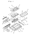
- FIG. 1 an exploded view of the assembly of a facsimile device according to a preferred embodiment of the present invention is shown.
- reference number 1 is the optical reading unit used for reading the original document (not shown) and includes an LED lamp 2, mirror 3, lens 4, and CCD circuit board 5;
- 6 is the original transport unit used for transporting the original document and includes original guide member 7 and original transport rollers 8;
- 9 is a printing unit including a printing head 10 and a flexible member 10a which presses said printer head 10 on a recording paper to be copied.
- Printer unit 9 is mounted below printer paper cover 11.
- An original width adjustment guide 24 is provided on top of printer paper cover 11.
- Reference number 12 is a keyboard unit used for operating the facsimile and including keypad 13 and display panel 14; 15 is an electrical circuit board; 16 is the base unit to which are mounted units 1, 6, 9, 11, 12, and 15.
- the base unit 16 includes a platen roller 17, oppositely located printing unit 9, and paper install chamber 18. Furthermore, drive motor 19 for driving original transport rollers 8 mounted in original transport unit 6, and drive motor 20 for driving platen roller 17 are provided in base unit 16.
- Reference numbers 21 and 22 are the side cabinets.
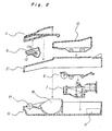
- Base unit 16 is constructed so that paper holder 18 and platen roller 17 are positioned at the front of base unit 16 (in the left of Fig. 2), and optical reading unit 1 and electrical circuit board 15 are positioned at the back of base unit 16 (in the right of Fig. 2).
- the original transport unit 6 is positioned above optical reading unit 1 at such a position that the original document can be transported to a predetermined reading position at optical reading unit 1.
- the keyboard unit 12, the bottom of which forms the original guide surface, is positioned above original transport unit 6.
- the printing unit 9, installed below printer paper cover 11, is located above and in contact with platen roller 17 of base unit 16.
- a cross section of the assembled facsimile device is shown.
- the assembly process is simplified and the height of the assembled product is lower because the printing unit is located to the front and the original reading unit is located to the back of the device.
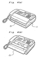
- Figs. 4a and 4b the perspective views of the assembled facsimile device are shown, particularly, Fig. 4(a) shows the device when the printer paper cover 11 on hopper 23 is closed, and Fig. 4(b) shows the device when hopper 23 is opened in the direction of the arrow.
- hopper 23 When hopper 23 is positioned as shown in Fig. 4(b), hopper 23 serves as the original feed table.
- the finished product has a lower profile and it is easier to replace the printer paper.
Abstract
Description
- The present invention relates to a facsimile device having an image reading mechanism and a printing mechanism.
- As shown in Fig. 5, a prior art facsimile device has the multiple components, such as the original document reading mechanism for reading the image of the original document and the printing mechanism, are each independently mounted to the cabinet of the facsimile, and the original document reading assembly is located in a position above that of the printing assembly.
- In the prior art facsimile device as thus described, because the various components are mounted directly to the main cabinet, mounting and adjusting the various components on the cabinet must be carried out on the assembly line, inviting increase of the manufacturing cost due to long assembly line with long time consuming word. Furthermore, it took long time for the service engineer to repair the facsimile device because the parts to be replaced must be disconnected from the cabinet.
- Moreover, because the original document reading assembly is positioned to the top with the printing assembly to the bottom, the size, particularly the height, of the facsimile becomes bulky. Besides that, it took time for the user to replace the paper because the reading assembly must be lifted up in order to have an access to the paper installing area.
- The present invention has been developed with a view to substantially solving the above-described problem and has for its essential object to provide an improved facsimile device which can be readily assembled and is compact in size.
- It is also an important object of the present invention to provide the above described type of facsimile device which improves productivity in the assembly process and improves the serviceability of the product.
- It is a further object of the present invention to provide a facsimile device which is thin and has a low profile.
- In accomplishing these and other objects, a facsimile device according to the present invention comprises: an optical reader unit comprising a light source for illuminating an original document, and an image reading element for receiving and reading the light reflected from said original document; an original transport unit comprising a feed roller and original guides for transporting said original document to an original reading position of said optical reader unit; a printing unit comprising a printer head and a flexible member which presses said printer head on a recording paper to be copied; and a base unit comprising a recording paper holder and a platen, said base unit provided for supporting each of said optical reader unit, said original transport unit and said printing unit.
- Also, according to the present invention, facsimile device comprises:
a printing assembly comprising: a printing unit comprising a printer head and a flexible member which presses said printer head on a recording paper to be copied; a recording paper holder; and a platen; and
a reader assembly comprising: an optical reader unit comprising a light source for illuminating an original document, and an image reading element for receiving and reading the light reflected from said original document; and an original transport unit comprising a feed roller for transporting the original document to a predetermined original reading position of said optical reader unit;
and is characterized in that the printing assembly and said reader assembly being positioned side by side. - These and other objects and features of the present invention will become clear from the following description taken in conjunction with the preferred embodiment thereof with reference to the accompanying drawings throughout which like parts are designated by like reference numerals, and in which:
- Fig. 1 is an exploded perspective view of a facsimile device according to a preferred embodiment of the present invention;
- Fig. 2 is a cross-sectional view of each unit;
- Fig. 3 is a cross-sectional view of the assembled facsimile device;
- Figs. 4a and 4b are perspective views of the facsimile device; and
- Fig. 5 is a cross-sectional view of the prior art facsimile device.
- Referring to Fig. 1, an exploded view of the assembly of a facsimile device according to a preferred embodiment of the present invention is shown. In Fig. 1,
reference number 1 is the optical reading unit used for reading the original document (not shown) and includes an LED lamp 2, mirror 3,lens 4, and CCD circuit board 5; 6 is the original transport unit used for transporting the original document and includes original guide member 7 andoriginal transport rollers 8; and 9 is a printing unit including aprinting head 10 and aflexible member 10a which presses saidprinter head 10 on a recording paper to be copied.Printer unit 9 is mounted belowprinter paper cover 11. An originalwidth adjustment guide 24 is provided on top ofprinter paper cover 11. -
Reference number 12 is a keyboard unit used for operating the facsimile and includingkeypad 13 anddisplay panel 14; 15 is an electrical circuit board; 16 is the base unit to which are mountedunits base unit 16 includes aplaten roller 17, oppositely locatedprinting unit 9, andpaper install chamber 18. Furthermore, drivemotor 19 for drivingoriginal transport rollers 8 mounted inoriginal transport unit 6, anddrive motor 20 fordriving platen roller 17 are provided inbase unit 16.Reference numbers - Referring to Fig. 2, a cross section of the assembled facsimile device of Fig. 1 is shown.
Base unit 16 is constructed so thatpaper holder 18 andplaten roller 17 are positioned at the front of base unit 16 (in the left of Fig. 2), andoptical reading unit 1 andelectrical circuit board 15 are positioned at the back of base unit 16 (in the right of Fig. 2). Theoriginal transport unit 6 is positioned aboveoptical reading unit 1 at such a position that the original document can be transported to a predetermined reading position atoptical reading unit 1. Thekeyboard unit 12, the bottom of which forms the original guide surface, is positioned aboveoriginal transport unit 6. - The
printing unit 9, installed belowprinter paper cover 11, is located above and in contact withplaten roller 17 ofbase unit 16. - Referring to Fig. 3, a cross section of the assembled facsimile device is shown. As can be understood from this figure, by assembling the facsimile device from functionally discrete units, the assembly process is simplified and the height of the assembled product is lower because the printing unit is located to the front and the original reading unit is located to the back of the device.
- Referring to Figs. 4a and 4b, the perspective views of the assembled facsimile device are shown, particularly, Fig. 4(a) shows the device when the
printer paper cover 11 onhopper 23 is closed, and Fig. 4(b) shows the device whenhopper 23 is opened in the direction of the arrow. Whenhopper 23 is positioned as shown in Fig. 4(b),hopper 23 serves as the original feed table. - By constructing a facsimile device from discrete functional units as described above, the assembly process is simplified. Thus, serviceability is improved by simplifying parts replacement, and it is easier to develop new models of the device.
- In addition, by positioning the reading assembly and the printing assembly side by side, the finished product has a lower profile and it is easier to replace the printer paper.
- Although the present invention has been fully described in connection with the preferred embodiment thereof with reference to the accompanying drawings, it is to be noted that various changes and modifications are apparent to those skilled in the art. Such changes and modifications are to be understood as defined by the appended claims unless they depart therefrom.
Claims (3)
an optical reader unit (1} comprising a light source (2) for illuminating an original document, and an image reading element (5) for receiving and reading the light reflected from said original document;
an original transport unit (6) comprising a feed roller (8) and original guides (7) for transporting said original document to an original reading position of said optical reader unit (1);
a printing unit (9) comprising a printer head (10) and a flexible member (10a) which presses said printer head (10) on a recording paper to be copied; and
a base unit (16) comprising a recording paper holder (18) and a platen (17), said base unit provided for supporting each of said optical reader unit (1), said original transport unit (6) and said printing unit (9).
a printing assembly comprising: a printing unit (9) comprising a printer head (10) and a flexible member (10a) which presses said printer head (10) on a recording paper to be copied; a recording paper holder (18); and a platen (17); and
a reader assembly comprising: an optical reader unit (1) comprising a light source (2) for illuminating an original document, and an image reading element (5) for receiving and reading the light reflected from said original document; and an original transport unit (6) comprising a feed roller (8) for transporting the original document to a predetermined original reading position of said optical reader unit (1);
said printing assembly and said reader assembly being positioned side by side.
Applications Claiming Priority (2)
| Application Number | Priority Date | Filing Date | Title |
|---|---|---|---|
| JP63247640A JP2798937B2 (en) | 1988-09-30 | 1988-09-30 | Facsimile machine |
| JP247640/88 | 1988-09-30 |
Publications (3)
| Publication Number | Publication Date |
|---|---|
| EP0361459A2 true EP0361459A2 (en) | 1990-04-04 |
| EP0361459A3 EP0361459A3 (en) | 1990-09-12 |
| EP0361459B1 EP0361459B1 (en) | 1994-06-22 |
Family
ID=17166506
Family Applications (1)
| Application Number | Title | Priority Date | Filing Date |
|---|---|---|---|
| EP89117904A Expired - Lifetime EP0361459B1 (en) | 1988-09-30 | 1989-09-27 | Facsimile device |
Country Status (6)
| Country | Link |
|---|---|
| US (1) | US5072307A (en) |
| EP (1) | EP0361459B1 (en) |
| JP (1) | JP2798937B2 (en) |
| AU (1) | AU602116B2 (en) |
| CA (1) | CA1337975C (en) |
| DE (1) | DE68916352T2 (en) |
Cited By (7)
| Publication number | Priority date | Publication date | Assignee | Title |
|---|---|---|---|---|
| EP0460659A2 (en) * | 1990-06-07 | 1991-12-11 | Canon Kabushiki Kaisha | Facsimile apparatus |
| EP0517007A1 (en) * | 1991-05-14 | 1992-12-09 | Sharp Kabushiki Kaisha | Facsimile device |
| EP0551888A1 (en) * | 1992-01-14 | 1993-07-21 | Canon Kabushiki Kaisha | Facsimile apparatus |
| EP0551889A1 (en) * | 1992-01-14 | 1993-07-21 | Canon Kabushiki Kaisha | Facsimile apparatus and roll-like sheet holder |
| EP0551890A1 (en) * | 1992-01-14 | 1993-07-21 | Canon Kabushiki Kaisha | Facsimile apparatus and functional expansion unit therefor |
| EP0561232A1 (en) * | 1992-03-07 | 1993-09-22 | Mita Industrial Co., Ltd. | Paper-supplying device |
| EP0582938A1 (en) * | 1992-08-11 | 1994-02-16 | Swatch Ag | Telecopier with pivotably mounted image pick-up device |
Families Citing this family (8)
| Publication number | Priority date | Publication date | Assignee | Title |
|---|---|---|---|---|
| US5327250A (en) * | 1989-03-31 | 1994-07-05 | Canon Kabushiki Kaisha | Facsimile device |
| KR910019383A (en) * | 1990-04-12 | 1991-11-30 | 고바야시 쥰 | Original Reading Device |
| JPH0649359Y2 (en) * | 1990-06-05 | 1994-12-14 | 株式会社スタッフ | Facsimile toys |
| US5265152A (en) * | 1990-09-03 | 1993-11-23 | Sharp Kabushiki Kaisha | Facsimile apparatus |
| JPH04110050U (en) * | 1991-02-01 | 1992-09-24 | 船井電機株式会社 | facsimile |
| JP3073045B2 (en) * | 1991-04-26 | 2000-08-07 | キヤノン株式会社 | Original image reading device |
| US5311330A (en) * | 1992-12-08 | 1994-05-10 | Silitek Corporation | Document guide roller assembly in a scanner |
| KR100186583B1 (en) * | 1996-06-26 | 1999-05-01 | 김광호 | Tti transmission auto-controlling method |
Citations (3)
| Publication number | Priority date | Publication date | Assignee | Title |
|---|---|---|---|---|
| JPS59125161A (en) * | 1982-12-30 | 1984-07-19 | Iwatsu Electric Co Ltd | Facsimile transmitting and receiving device |
| US4496988A (en) * | 1980-12-10 | 1985-01-29 | Fuji Xerox Co., Ltd. | Copying machine |
| EP0263319A2 (en) * | 1986-09-11 | 1988-04-13 | Canon Kabushiki Kaisha | Method of recording images |
Family Cites Families (7)
| Publication number | Priority date | Publication date | Assignee | Title |
|---|---|---|---|---|
| GB1515606A (en) * | 1975-12-23 | 1978-06-28 | Ibm | Electrophotographic apparatus |
| US4438459A (en) * | 1976-08-27 | 1984-03-20 | Levine Alfred B | Multiplex photocopier system with portable scanner |
| DE3118459C2 (en) * | 1981-05-09 | 1984-01-26 | Dr.-Ing. Rudolf Hell Gmbh, 2300 Kiel | Light receiving device |
| JPS58166338A (en) * | 1982-03-27 | 1983-10-01 | Ricoh Co Ltd | Optical apparatus |
| DE3439535A1 (en) * | 1984-10-29 | 1986-04-30 | Buchmann Rudolf Ch | PROTECTIVE SYSTEM DEVICES AND DEVICES FOR PREVENTING THE ABUSE OF ELECTRONICALLY TRANSFERRED DATA PRINTED OR COPIED AT THE END OUTPUT AND METHOD FOR THEIR HANDLING |
| JPS61225966A (en) * | 1985-03-29 | 1986-10-07 | Nippon Telegr & Teleph Corp <Ntt> | Facsimile equipment |
| JP2763116B2 (en) * | 1988-10-31 | 1998-06-11 | 株式会社東芝 | Image forming device |
-
1988
- 1988-09-30 JP JP63247640A patent/JP2798937B2/en not_active Expired - Fee Related
-
1989
- 1989-09-25 AU AU41707/89A patent/AU602116B2/en not_active Ceased
- 1989-09-26 CA CA000613125A patent/CA1337975C/en not_active Expired - Fee Related
- 1989-09-26 US US07/412,493 patent/US5072307A/en not_active Expired - Lifetime
- 1989-09-27 DE DE68916352T patent/DE68916352T2/en not_active Expired - Fee Related
- 1989-09-27 EP EP89117904A patent/EP0361459B1/en not_active Expired - Lifetime
Patent Citations (3)
| Publication number | Priority date | Publication date | Assignee | Title |
|---|---|---|---|---|
| US4496988A (en) * | 1980-12-10 | 1985-01-29 | Fuji Xerox Co., Ltd. | Copying machine |
| JPS59125161A (en) * | 1982-12-30 | 1984-07-19 | Iwatsu Electric Co Ltd | Facsimile transmitting and receiving device |
| EP0263319A2 (en) * | 1986-09-11 | 1988-04-13 | Canon Kabushiki Kaisha | Method of recording images |
Non-Patent Citations (1)
| Title |
|---|
| PATENT ABSTRACTS OF JAPAN vol. 8, no. 250 (E-279)(1687) 16 November 1984, & JP-A-59 125161 (IWASAKI TSUSHINKI K.K.) 19 July 1984, * |
Cited By (14)
| Publication number | Priority date | Publication date | Assignee | Title |
|---|---|---|---|---|
| US5335083A (en) * | 1990-06-07 | 1994-08-02 | Canon Kabushiki Kaisha | Circuit substrate holding apparatus for a facsimile |
| EP0460659A3 (en) * | 1990-06-07 | 1992-03-18 | Canon Kabushiki Kaisha | Facsimile apparatus |
| EP0460659A2 (en) * | 1990-06-07 | 1991-12-11 | Canon Kabushiki Kaisha | Facsimile apparatus |
| EP0517007A1 (en) * | 1991-05-14 | 1992-12-09 | Sharp Kabushiki Kaisha | Facsimile device |
| EP0551888A1 (en) * | 1992-01-14 | 1993-07-21 | Canon Kabushiki Kaisha | Facsimile apparatus |
| EP0551890A1 (en) * | 1992-01-14 | 1993-07-21 | Canon Kabushiki Kaisha | Facsimile apparatus and functional expansion unit therefor |
| EP0551889A1 (en) * | 1992-01-14 | 1993-07-21 | Canon Kabushiki Kaisha | Facsimile apparatus and roll-like sheet holder |
| US5379121A (en) * | 1992-01-14 | 1995-01-03 | Canon Kabushiki Kaisha | Portable facsimile apparatus |
| US5448374A (en) * | 1992-01-14 | 1995-09-05 | Canon Kabushiki Kaisha | Facsimile apparatus and roll-like sheet holder |
| US5706101A (en) * | 1992-01-14 | 1998-01-06 | Canon Kabushiki Kaisha | Facsimile apparatus with functional expansion unit |
| EP0561232A1 (en) * | 1992-03-07 | 1993-09-22 | Mita Industrial Co., Ltd. | Paper-supplying device |
| US5390906A (en) * | 1992-03-07 | 1995-02-21 | Mita Industrial Co., Ltd. | Paper supplying device |
| EP0582938A1 (en) * | 1992-08-11 | 1994-02-16 | Swatch Ag | Telecopier with pivotably mounted image pick-up device |
| FR2694858A1 (en) * | 1992-08-11 | 1994-02-18 | Swatch Ag | Fax machine having a pivotally supported image reading device. |
Also Published As
| Publication number | Publication date |
|---|---|
| EP0361459A3 (en) | 1990-09-12 |
| AU602116B2 (en) | 1990-09-27 |
| AU4170789A (en) | 1990-04-05 |
| DE68916352T2 (en) | 1995-02-02 |
| JPH0295083A (en) | 1990-04-05 |
| EP0361459B1 (en) | 1994-06-22 |
| CA1337975C (en) | 1996-01-23 |
| DE68916352D1 (en) | 1994-07-28 |
| JP2798937B2 (en) | 1998-09-17 |
| US5072307A (en) | 1991-12-10 |
Similar Documents
| Publication | Publication Date | Title |
|---|---|---|
| US5072307A (en) | Facsimile device | |
| US4768100A (en) | Image processing apparatus | |
| US6167221A (en) | Image forming apparatus with separate support structures for image forming parts and for other parts | |
| US4704638A (en) | Image information reading device | |
| US5739925A (en) | Facsimile apparatus cover and feeding mechanism | |
| JPH0830062A (en) | Image forming device | |
| US7202980B2 (en) | Mounting structure for inverter circuit board for light source lamp of image reader | |
| KR20030010570A (en) | Original document scanning apparatus | |
| US5781313A (en) | Flat bed scanner | |
| JP3031519B2 (en) | Document reading device and facsimile device | |
| JPH08340418A (en) | Medium conveyance device and electronic device | |
| KR100190342B1 (en) | Lens supporting device for photograph printing machine | |
| JPH07162568A (en) | Facsimile equipment | |
| JP2729681B2 (en) | Automatic document feeder / ejector | |
| EP0333320A2 (en) | Apparatus for scanning reading of documents of different formats | |
| EP0516092B1 (en) | Image reader | |
| EP0467264B1 (en) | Cabinet structure of facsimile apparatus | |
| JP2007086357A (en) | Image forming apparatus | |
| KR910001132Y1 (en) | Multifunction sheet tray of electronic copier | |
| EP0517007B1 (en) | Facsimile device | |
| JP2622975B2 (en) | Document reading device | |
| JP2023125482A (en) | Image forming apparatus | |
| JPH01151361A (en) | Original reader | |
| JP2613965B2 (en) | Facsimile machine | |
| KR100584586B1 (en) | Image scanning apparatus |
Legal Events
| Date | Code | Title | Description |
|---|---|---|---|
| PUAI | Public reference made under article 153(3) epc to a published international application that has entered the european phase |
Free format text: ORIGINAL CODE: 0009012 |
|
| AK | Designated contracting states |
Kind code of ref document: A2 Designated state(s): DE FR GB |
|
| PUAL | Search report despatched |
Free format text: ORIGINAL CODE: 0009013 |
|
| AK | Designated contracting states |
Kind code of ref document: A3 Designated state(s): DE FR GB |
|
| 17P | Request for examination filed |
Effective date: 19901219 |
|
| 17Q | First examination report despatched |
Effective date: 19921216 |
|
| GRAA | (expected) grant |
Free format text: ORIGINAL CODE: 0009210 |
|
| AK | Designated contracting states |
Kind code of ref document: B1 Designated state(s): DE FR GB |
|
| REF | Corresponds to: |
Ref document number: 68916352 Country of ref document: DE Date of ref document: 19940728 |
|
| ET | Fr: translation filed | ||
| PLBE | No opposition filed within time limit |
Free format text: ORIGINAL CODE: 0009261 |
|
| STAA | Information on the status of an ep patent application or granted ep patent |
Free format text: STATUS: NO OPPOSITION FILED WITHIN TIME LIMIT |
|
| 26N | No opposition filed | ||
| REG | Reference to a national code |
Ref country code: GB Ref legal event code: IF02 |
|
| PGFP | Annual fee paid to national office [announced via postgrant information from national office to epo] |
Ref country code: FR Payment date: 20060908 Year of fee payment: 18 |
|
| PGFP | Annual fee paid to national office [announced via postgrant information from national office to epo] |
Ref country code: DE Payment date: 20060922 Year of fee payment: 18 |
|
| PGFP | Annual fee paid to national office [announced via postgrant information from national office to epo] |
Ref country code: GB Payment date: 20060927 Year of fee payment: 18 |
|
| GBPC | Gb: european patent ceased through non-payment of renewal fee |
Effective date: 20070927 |
|
| PG25 | Lapsed in a contracting state [announced via postgrant information from national office to epo] |
Ref country code: DE Free format text: LAPSE BECAUSE OF NON-PAYMENT OF DUE FEES Effective date: 20080401 |
|
| REG | Reference to a national code |
Ref country code: FR Ref legal event code: ST Effective date: 20080531 |
|
| PG25 | Lapsed in a contracting state [announced via postgrant information from national office to epo] |
Ref country code: FR Free format text: LAPSE BECAUSE OF NON-PAYMENT OF DUE FEES Effective date: 20071001 |
|
| PG25 | Lapsed in a contracting state [announced via postgrant information from national office to epo] |
Ref country code: GB Free format text: LAPSE BECAUSE OF NON-PAYMENT OF DUE FEES Effective date: 20070927 |