EP0361662A1 - Dual source parenteral infusion system with secondary infusion module - Google Patents
Dual source parenteral infusion system with secondary infusion module Download PDFInfo
- Publication number
- EP0361662A1 EP0361662A1 EP89308227A EP89308227A EP0361662A1 EP 0361662 A1 EP0361662 A1 EP 0361662A1 EP 89308227 A EP89308227 A EP 89308227A EP 89308227 A EP89308227 A EP 89308227A EP 0361662 A1 EP0361662 A1 EP 0361662A1
- Authority
- EP
- European Patent Office
- Prior art keywords
- solution
- primary
- module
- drip chamber
- infusion
- Prior art date
- Legal status (The legal status is an assumption and is not a legal conclusion. Google has not performed a legal analysis and makes no representation as to the accuracy of the status listed.)
- Granted
Links
Images


Classifications
-
- A—HUMAN NECESSITIES
- A61—MEDICAL OR VETERINARY SCIENCE; HYGIENE
- A61M—DEVICES FOR INTRODUCING MEDIA INTO, OR ONTO, THE BODY; DEVICES FOR TRANSDUCING BODY MEDIA OR FOR TAKING MEDIA FROM THE BODY; DEVICES FOR PRODUCING OR ENDING SLEEP OR STUPOR
- A61M5/00—Devices for bringing media into the body in a subcutaneous, intra-vascular or intramuscular way; Accessories therefor, e.g. filling or cleaning devices, arm-rests
- A61M5/14—Infusion devices, e.g. infusing by gravity; Blood infusion; Accessories therefor
- A61M5/168—Means for controlling media flow to the body or for metering media to the body, e.g. drip meters, counters ; Monitoring media flow to the body
- A61M5/16804—Flow controllers
- A61M5/16827—Flow controllers controlling delivery of multiple fluids, e.g. sequencing, mixing or via separate flow-paths
-
- Y—GENERAL TAGGING OF NEW TECHNOLOGICAL DEVELOPMENTS; GENERAL TAGGING OF CROSS-SECTIONAL TECHNOLOGIES SPANNING OVER SEVERAL SECTIONS OF THE IPC; TECHNICAL SUBJECTS COVERED BY FORMER USPC CROSS-REFERENCE ART COLLECTIONS [XRACs] AND DIGESTS
- Y10—TECHNICAL SUBJECTS COVERED BY FORMER USPC
- Y10S—TECHNICAL SUBJECTS COVERED BY FORMER USPC CROSS-REFERENCE ART COLLECTIONS [XRACs] AND DIGESTS
- Y10S128/00—Surgery
- Y10S128/13—Infusion monitoring
Definitions
- This invention relates to infusion systems which control the delivery of two sources of parenteral solutions to a patient and, in particular, to apparatus for monitoring and controlling the solutions being delivered in these systems.
- a pinch valve on the controller occludes the secondary tubing set and solution begins to flow from the primary source.
- the delivery of primary solution is monitored by a drop detector and drip chamber on the primary controller, and its flow is controlled by the control valve.
- a check valve in the primary administration set prevents flow of the primary solution while the secondary solution is being delivered.
- U.S. Patent 4,533,347 shows a similar system in which the drip chamber for the primary solution is located in the primary administration set.
- the drop detector for the primary solution is located about this drip chamber, remote from the primary controller.
- each administration set includes a drip chamber and an associated drop detector. Operation of the system is as described for the '592 patent.
- U.S. Patent 4,637,817 shows a dual source infusion system in which each administration set passes through a sequenced pinch valve above the Y-connector.
- the pinch valve alternately opens one of the tubing sets and closes the other, and the flow of parenteral solution is controlled by a pump located on the controller.
- the use of the sequenced pinch valve obviates the need for a check valve in the primary solution line, since the valve permits the flow of only one solution at a time.
- a user To initialize the system prior to fluid delivery, a user must enter flow rate and total dose values into the primary controller. As the values are entered, they are displayed on the primary controller display. The values for the two solution sources are separately entered and displayed. That is, the user first enters the values for one solution source and observes their entry on the display. The display is then cleared, and the user enters and observes the values for the other solution source. During operation of the system, the delivery rate and volume of the solution being delivered at that time are viewed on the display.
- a nurse should be able to immediately note both the progress of secondary solution delivery and the dose previously delivered from the primary source without manipulating the system or interrupting the flow of primary solution.
- a dual source parenteral infusion system which enables a user to unambiguously control and monitor the delivery of the two solutions.
- the primary controller of the system includes means for controlling the rate of fluid delivery, means for entering values for controlling the delivery of the primary solution, and a display for displaying both the entry of the primary solution delivery values and the progress of primary solution delivery.
- a secondary infusion module communicates with the primary controller and is adapted for coupling to the secondary administration set.
- the secondary infusion module includes means for monitoring the delivery of secondary solution, and a display for displaying the progress of secondary solution delivery.
- the secondary infusion module provides a display which is unambiguously located in proximity to the secondary administration set.
- entry of the secondary solution delivery values is provided at the secondary infusion module.
- the user can visually ascertain the parameters for secondary solution delivery directly on the display of the secondary infusion module.
- the secondary infusion module also includes means for opening and occluding a conduit in the secondary administration set as infusion of the secondary solution commences and terminates.
- FIGURE 1 a dual source parenteral infusion system constructed in accordance with the principles of the present invention is shown.
- a source 2 of a primary solution is suspended from a pole 1.
- the primary solution is delivered to a drip chamber 26, about which is mounted a drop detector 4.
- Tubing 8 of a primary solution administration set leads from the drip chamber to a Y-connector 10, and includes an in-line one-way check valve 6.
- the outlet of the Y-connector is connected by common tubing 12 to a precision control valve 22, which is mounted on a primary controller 20.
- An outlet tubing line 14 leads from the control valve 22 to the infusion site.
- a display 28 On the right-hand side of the front of the primary controller 20 is a display 28, which displays values indicating the progress of infusion of the primary solution. Below the display 28 is a group of pushbutton controls 30 for entry of values for controlling infusion of the primary solution. As the values are entered prior to operation of the system they may be viewed on the display 28.
- an interface box 32 At the bottom of the central controller 20 is an interface box 32, which connects the primary controller to the drop dectector 4 and to a secondary infusion module 40 by way of cables 34 and 36.
- a secondary solution source 24 Also suspended from the pole 1 is a secondary solution source 24.
- Tubing 16 of a secondary administration set connects the secondary solution supply to a second input port of the Y-connector 10.
- a second drip chamber Located just below the secondary solution source 24 is a second drip chamber. This drip chamber is not visible in FIGURE 1, as it is located inside the secondary infusion module 40.
- the secondary infusion module mounts around the second drip chamber in the same manner as the drop detector 4 mounts around drip chamber 26.
- the secondary infusion module includes a display area 42 which displays parameters indicating the progress of delivery of the secondary solution. Below the display area is a group of pushbutton controls 44. These controls permit entry of the values governing delivery of the secondary solution directly at the secondary infusion module. As the values are entered they may be visually ascertained directly on the display 42.
- One of the two pushbuttons at the bottom of the secondary infusion module controls an internal mechanism which opens and occludes the tubing line 16 as it passes through the secondary infusion module. The other
- FIGURE 2a a primary controller 20 is shown.
- a display 28 On the right-hand side of the front of the controller 20 is a display 28.
- an eight character message center 122 which displays error and other status messages.
- the individual characters in the message are each comprised of fourteen individually controlled segments to form the desired alphanumeric characters.
- Below and to the left of the message center is an instrument logo design 124 which pulses when the primary controller is operating.
- Below the logo design are three large numbers which indicate the flow rate in ml/hr at which the primary controller is currently operating. To the left of the numbers is the descriptor "FLOW RATE," and above the numbers are the units of ml/hr.
- the top line represents a fluid code which a user may enter to specify the type of solution being administered.
- the next line specifies the dose remaining to be delivered of the total dose programmed into the controller at the beginning of the procedure.
- the third line specifies the remaining time for completion of the administration of the programmed dose, and the fourth line indicates the volume of the programmed dose already administered.
- Pushbuttons 130 are used to increment or decrement a value during programming of the controller.
- Pushbutton 132 is used to turn the controller off or on.
- the "SELECT” pushbutton 134 is used to select a value which is to be programmed into the controller, such as "dose” or "flow rate.”
- the "SELECT” pushbutton may also be used to change values during fluid delivery by holding the "SELECT” pushbutton down while incrementing or decrementing a value with the up/down pushbuttons.
- Pushbutton 136 is depressed to stop the administration of solution, and pushbutton 138 is depressed to start fluid administration in accordance with the values programmed into the controller.
- the control valve 22 shown in FIGURE 2a is a precision pinch valve which encloses tubing line 12, 14, and is described in greater detail in U.S. Patent 4,559,045. Inside the pinch valve the tubing is engaged between a movable pressure plate and a stationary pressure plate. A precision motor-driven actuator projects from the front of the controller and is in contact with the movable pressure plate to controllably move the movable pressure plate toward and away from the interposed tubing. The tubing is thereby selectively occluded to control the rate of flow of fluid through the outlet tubing 14.
- a drip chamber 80 has a cap 98 with an integrally molded drop former.
- a lip 94 at the bottom of the cap snaps into a retaining ring 54 at the top of a drop detector 56.
- the drip chamber is properly located within the drop detector 56, its presence is detected by a door 60 which is hinged as indicated at 63. Falling drops within the drip chamber are detected by the optical path indicated by the arrows at the top of the chamber and their passage is used by the primary controller to measure the flow of primary solution.
- a precision pinch valve 70 below the drip chamber 80 selectively occludes the outlet tubing 14 to regulate the flow of parenteral solution to the patient.
- the drop detector 4 and the drip chamber 26 of FIGURE 1 are shown in detail in FIGURES 3 and 4.
- the drop detector 4 is seen to comprise a housing which encloses photodiodes and photodetectors for an optical drop detector 62 and an optical level detector 66.
- a spring hinged door 60 is located within the cavity in the center of the housing and projects forward in the absence of a drip chamber in the housing, in which position it blocks the optical path of the drop detector 62.
- At the top of the housing is a split mounting ring 54.
- the drop detector 4 is mounted about the drip chamber 26 in FIGURE 4 by snapping the lip 94 of the spike 95 at the top of the chamber into the mounting ring 54.
- the spike 95 is inserted into a parenteral solution bag or membrane in the cap of the suspended fluid source prior to mounting the drop detector.
- the chamber presses the hinged door 60 to the rear of the cavity, thereby unblocking the optical path of the drop detector 62.
- the drop detector is able to sense the proper mounting of the drip chamber by the deflection of the door 60, and also senses proper priming of the drip chamber by the obscuring of the level detector 66 with fluid while the optics of drop detector 62 are unobscured.
- droplets will fall from the drop former and be detected by the optical drop detector 62.
- a detailed description of the drop detector 4 is presented in U.S. Patent Application SN 117,009, filed November 4, 1987.
- the secondary infusion module of the present invention is shown in the front and back views of FIGURES 5 and 6.
- a display 42 shown in FIGURE 5.
- a five character message center 72 is located at the top of the display. These fourteen segment characters display alarm and status conditions during the administration of the secondary solution.
- an instrument logo design 74 which pulses during delivery of the secondary solution.
- Below the logo are three large characters 76 which display the flow rate of the solution.
- the descriptor "FLOW RATE” and the flow units of ml/hr are displayed above the flow rate numerals.
- Below the flow rate are three and one-half characters 78 which display the dose being administered, together with the descriptor "DOSE" and the units of ml.
- a series of pushbuttons 44 which are used to program and operate the module 40.
- the "SELECT" pushbutton 82 is depressed to program the module. When this pushbutton is depressed, the descriptor and units of the value being entered flash on the display, and the value is incremented or decremented by depressing the up/down pushbuttons 86.
- the "STANDBY” pushbutton 84 is depressed to stop the administration of the secondary solution and start the administration of the primary solution, or to clear the alarms on the secondary infusion module.
- Below the pushbuttons 86 is a “Load” key 88, which is depressed while mounting the secondary infusion module around the secondary drip chamber.
- An “Infuse” key 90 is depressed to begin the administration of the secondary solution.
- the side of the secondary infusion module is shown in FIGURE 6.
- a cavity 100 in the module is accessible from the side for insertion of the secondary drip chamber shown in FIGURE 7.
- At the top of the module is a mounting ring 92, similar to the mounting ring 54 of the drop detector 4.
- the secondary infusion module is mounted around the secondary drip chamber 81 by inserting the lip 94 of the drip chamber spike 95 into the mounting ring 92.
- the drip chamber 81 is positioned in the optical path of a drop detector 102, 102′, and in the optical path of a low level detector 106, 106′.
- a barrier 93 To properly engage the drip chamber in the cavity 100 a barrier 93 must be withdrawn from the bottom of the cavity 100.
- the barrier is withdrawn by depressing the "Load” key, whereupon the tubing section 16 is located in the passage at the bottom of the cavity.
- the barrier 93 pinches the tubing section 16 closed. Fluid flow is thereby prevented until the "Infuse” key is depressed at the commencement of secondary infusion.
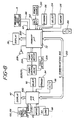
- Control of the dual source infusion system of FIGURE 1 is provided by two microprocessors, one located in the primary controller and another in the secondary infusion module, as shown in block diagram form in FIGURE 8.
- the microprocessor 200 in the primary controller 20 interacts with other components of the primary controller as shown in the FIGURE.
- the microprocessor 200 activates and controls the display 28 and an alarm 208. It also controls a motor 204 for the pump or control valve, which in turn is connected to the pump or valve.
- Fault detector electronics 206 monitors the operation of the pump or valve and informs the microprocessor 200 of the pump or valve operation. Faults detected by the electronics 206 are conditions related to flow, such as slow flow, no flow, or an occlusion at the infusion site. When any of these conditions are detected, the microprocessor 200 will verify them and sound the alarm 208 and cease system operation until the alarm condition is remedied.
- the primary microprocessor 200 receives information on primary solution drop detection from the primary drop detector 4 which indicate an alarm condition, such as high or low solution level in the primary drip chamber, no drops, or a continuous stream of drops. Whenever any of these conditions are detected the microprocessor 200 will verify the problem, activate the alarm and cease system operation.
- an alarm condition such as high or low solution level in the primary drip chamber, no drops, or a continuous stream of drops.
- the primary controller 20 is initially turned on by closure of the on/off switch 132, which connects the microprocessor and other electronics to a power source 210.
- the microprocessor 200 also receives inputs from the standby pushbutton 136, the SELECT pushbutton 134, the infuse pushbutton 138, and the up/down pushbuttons 130.
- the microprocessor 300 in the secondary infusion module 40 activates and controls the display 42.
- the microprocessor 300 receives secondary solution drop detection information from the integral secondary drop detector 102 and level detector 106, in particular drop detection and high or low level information, as well as notification that the drip chamber 81 has been properly mounted.
- the Load key 88, the Infuse key 90, the SELECT pushbutton 82, the STANDBY pushbutton 84, and the up/down pushbuttons 86 also are connected to provide inputs to the microprocessor 300.
- the two microprocessors are interconnected by a 6-line communications bus 250, enclosed within the cable 34.
- the six lines include a transmit line, a receive line, a clock line, a V CC regulated voltage line, a V batt battery voltage line, and a ground line.
- transceivers one of which is located in the interface 32 at the bottom of the primary controller.
- a second transceiver is located in the secondary infusion module 40. Redundant transmissions are employed to assure data integrity.
- An infusion procedure may be commenced using the system of the present invention by starting to administer the secondary solution first, then changing over to administration of the primary solution.
- One advantage of the arrangement of the present invention is that secondary solution administration can be commenced while the administration of primary solution is in progress, whereafter the system will revert back to primary solution administration when the administration of secondary solution is completed. Operation of the system of the present invention will be illustrated by explaining the latter process.
- the container is suspended from the pole, and the primary administration set (including drip chamber 26, tubing section 8, check valve 6, Y-connector 10, tubing section 12, pinch valve 22, 79 or cassette 50, and tubing section 14) is connected to the solution container and primed with solution.
- the primary administration set (including drip chamber 26, tubing section 8, check valve 6, Y-connector 10, tubing section 12, pinch valve 22, 79 or cassette 50, and tubing section 14) is connected to the solution container and primed with solution.
- the primary controller is programmed by entering values for the total dose in ml and the flow rate in ml/hr, using the SELECT pushbutton 134 and the up/down pushbuttons 130. As the values are entered they are verified visually on the primary display 28. When the the primary solution values are properly entered the clamp on the tubing set is released and the infuse pushbuttons 138 is depressed to begin infusion.
- the microprocessor 200 will thereupon execute a series of hardware and software checks to verify that the system is connected and operating properly, and will begin to control the pump or precision valve mechanism to adjust for the desired flow rate. As the infusion proceeds, information on the rate of progress is displayed on the primary display 28.
- the administration of primary solution may be interrupted by the administration of the secondary solution as follows.
- a hook which is a part of the secondary administration set is used to suspend the primary solution container from the pole at a level below that of the secondary solution container.
- the secondary solution container is suspended from the pole and the secondary administration set (including the secondary drip chamber 81 and the tubing line 16) is connected to the container and primed with solution.
- the tubing line 16 is clamped and a needle at the end of tubing section 16 is inserted into the Y-connector 10.
- the secondary infusion module 40 is mounted about the secondary drip chamber 81 by inserting the drip chamber 81 into the cavity at the side of the module while depressing then releasing the Load key.
- the module is then programmed for the values of secondary solution delivery by depressing the SELECT pushbutton 82 and the up/down pushbuttons 86. Entry of the correct values is visually confirmed by viewing the display 42 on the module. The clamp on the administration set is released and delivery of the secondary solution begun by depressing the Infuse key on the module.
- the secondary infusion module As soon as the secondary infusion module is connected to the primary controller, power is provided to the module 40 from the primary controller and the microprocessors in the two units begin exchanging status bytes of information. During this period of initialization the secondary microprocessor 300 executes a series of hardware and software checks to assure that the secondary system is connected and operating properly. Once the Infuse key has been depressed, an intense burst of communication between the two microprocessors begins. The microprocessor 300 sends a burst of twelve 8-bit bytes to the microprocessor 200 over the communications bus 250. This data burst informs the primary controller as to the infusion parameters to be used for controlling the dose and flow rate.
- the received data is echoed back to the module for verification and the primary microprocessor begins to adjust the flow control mechanism for the proper rate of fluid delivery of the secondary solution.
- the two microprocessors resume exchanging status information at a low level.
- the primary controller sends eight-bit bytes to the secondary microprocessor 300, each byte containing a "dose decrement” bit, a primary alarm bit, a "stop infuse” bit, and an unused bit. These four bits are repeated in the last four bits of the byte for redundancy checking. Delivery of the secondary solution commences as the pressure head of the secondary solutions closes the check valve 6 and the secondary solution flows into the pump or control valve mechanism.
- the microprocessor 300 monitors the drop formation and fluid level in the secondary drip chamber 81. Every eight milliseconds the secondary microprocessor 81 transmits an 8-bit status byte to the primary microprocessor. Each byte contains an alarm bit, a drop sense bit, a start/stop bit, and a level bit. These four bits are replicated in the second four bits of the byte for redundancy. Whenever a falling drop is detected in the secondary drip chamber the drop sense bit is set in the transmitted byte, and held for 100 milliseconds for debounce purposes. The start/stop bit is set and held after the Infuse key is depressed, and is released only when secondary infusion is completed.
- the secondary infusion module is shut down and the infusion of primary solution resumes.
- the other bits in the status byte including the alarm bit and the level bit, are checked by the primary microprocessor 200 every 72 milliseconds.
- the level bit is set if the secondary microprocessor detects the presence of fluid at the level of detector 106, 106′ in the secondary drip chamber 81.
- the secondary infusion module When the secondary infusion module is delivering the secondary solution, either after interrupting primary solution delivery or by starting the system with initial delivery of the secondary solution, there are several ways of terminating secondary solution delivery.
- One way is to deliver the programmed dose of secondary solution, whereupon system operation switches over from the secondary module to the primary controller. It is possible to deliver not just a measured dose, but the entire supply of secondary solution.
- the module is programmed to do this by decrementing from a dose of "000" using the up/down keys, whereupon the dose display reads "ALL.”
- the delivery of the full supply of solution is detected by a low level detection in the secondary drip chamber.
- the third type of error is a hardware or software malfunction or communication link problem, which may be detected by either the primary controller or the secondary module.
- the dual source infusion system of FIGURE 1 may be operated by first suspending the solution containers from the pole.
- the primary administration set is connected to the primary solution container and is primed with solution and clamped.
- the secondary administration set is connected to the secondary solution container, primed, clamped, and connected to the Y-connector of the primary administration set.
- the primary controller 20 is programmed for delivery of the primary solution by entering the flow rate, dose, and any other information necessary such as the fluid code. As these values are programmed into the controller with the pushbuttons 30 they may be visually verified on the display 28.
- the secondary infusion module 40 is then programmed for delivery of the secondary solution using the pushbuttons 44 on the module. The values for the dose and flow rate of the secondary solution can be observed directly on the module display 42 as they are entered.
- both units When both units are programmed the delivery of the secondary solution is commenced by depressing the Infuse key. As fluid delivery continues, the progress of secondary fluid delivery can be seen immediately on the module display 42, and the programmed values for the primary solution can be checked by viewing them on the primary controller display 28. When the programmed dose of secondary solution has been delivered, the total volume of solution delivered can be viewed on the controller display and the volume of primary solution remaining to be delivered can be simultaneously viewed on the controller display. Information as to the delivery of both solutions is thus readily and unambiguously apparent to the user without any manipulation of either the module or the controller.
Abstract
Description
- This invention relates to infusion systems which control the delivery of two sources of parenteral solutions to a patient and, in particular, to apparatus for monitoring and controlling the solutions being delivered in these systems.
- Systems for delivering predetermined volumes of two parenteral solutions at predetermined flow rates have been known for a number of years. On such system is shown in U.S. Patent 4,576,592. In that system, a primary administration tubing set and a secondary administration tubing set are joined at a "Y" connector and connected through a common conduit to a drip chamber on the primary controller. Below the drip chamber is a precision flow control valve for regulating the flow of solution through the common conduit. A second drip chamber in the secondary administration set is monitored by a drop detector which is electrically connected to the primary controller. Parenteral solution is initially supplied by the secondary solution source, and its delivery is monitored by the drop detector and its flow is controlled by the control valve. When delivery of the secondary solution is completed a pinch valve on the controller occludes the secondary tubing set and solution begins to flow from the primary source. The delivery of primary solution is monitored by a drop detector and drip chamber on the primary controller, and its flow is controlled by the control valve. A check valve in the primary administration set prevents flow of the primary solution while the secondary solution is being delivered.
- U.S. Patent 4,533,347 shows a similar system in which the drip chamber for the primary solution is located in the primary administration set. The drop detector for the primary solution is located about this drip chamber, remote from the primary controller. Thus, each administration set includes a drip chamber and an associated drop detector. Operation of the system is as described for the '592 patent.
- U.S. Patent 4,637,817 shows a dual source infusion system in which each administration set passes through a sequenced pinch valve above the Y-connector. The pinch valve alternately opens one of the tubing sets and closes the other, and the flow of parenteral solution is controlled by a pump located on the controller. The use of the sequenced pinch valve obviates the need for a check valve in the primary solution line, since the valve permits the flow of only one solution at a time.
- Dual source administration systems are also shown in U.S. Patents 3,886,937; 3,982,534; 4,094,318; 4,114,617; and 4,300,552.
- The prior art systems described above are all similar in one respect. To initialize the system prior to fluid delivery, a user must enter flow rate and total dose values into the primary controller. As the values are entered, they are displayed on the primary controller display. The values for the two solution sources are separately entered and displayed. That is, the user first enters the values for one solution source and observes their entry on the display. The display is then cleared, and the user enters and observes the values for the other solution source. During operation of the system, the delivery rate and volume of the solution being delivered at that time are viewed on the display.
- With only a single set of value entry controls it is at times confusing for the user to be certain that the values being entered are associated with the proper solution. It would be desirable to provide an unambiguous way of entering the values for fluid delivery for the two solution sources. Moreover, with only a single display, it is often confusing to discern which source is delivering fluid, and what the state is of the other source. It would be desirable for a user to be able to discern at a glance which source is delivering fluid at any point in time. It would further be desirable to be able to quickly ascertain the delivery state of both solutions. For instance, when the delivery of fluid from the second source has ended and the delivery of primary solution has commenced, a nurse should be able to immediately note both the progress of secondary solution delivery and the dose previously delivered from the primary source without manipulating the system or interrupting the flow of primary solution.
- In accordance with the principles of the present invention, a dual source parenteral infusion system is provided which enables a user to unambiguously control and monitor the delivery of the two solutions. The primary controller of the system includes means for controlling the rate of fluid delivery, means for entering values for controlling the delivery of the primary solution, and a display for displaying both the entry of the primary solution delivery values and the progress of primary solution delivery. A secondary infusion module communicates with the primary controller and is adapted for coupling to the secondary administration set. The secondary infusion module includes means for monitoring the delivery of secondary solution, and a display for displaying the progress of secondary solution delivery. Thus, the secondary infusion module provides a display which is unambiguously located in proximity to the secondary administration set.
- In a preferred embodiment, entry of the secondary solution delivery values is provided at the secondary infusion module. The user can visually ascertain the parameters for secondary solution delivery directly on the display of the secondary infusion module. The secondary infusion module also includes means for opening and occluding a conduit in the secondary administration set as infusion of the secondary solution commences and terminates.
- In the drawings:
- FIGURE 1 illustrates a dual source parenteral infusion system constructed in accordance with the principles of the present invention;
- FIGURES 2a-2c illustrate primary controllers suitable for use in the infusion system of FIGURE 1;
- FIGURE 3 illustrates a drop detector suitable for use with the primary drip chamber in FIGURE 1;
- FIGURE 4 illustrates the drop detector of FIGURE 3 when mounted on the primary drip chamber;
- FIGURES 5 and 6 illustrate the secondary infusion module of the infusion system of FIGURE 1;
- FIGURE 7 illustrates a spike and drip chamber suitable for use in the secondary administration set with the secondary infusion module of FIGURES 5 and 6; and
- FIGURE 8 illustrates in block diagram form the location and interaction of control functions in the infusion system of FIGURE 1.
- Referring first to FIGURE 1, a dual source parenteral infusion system constructed in accordance with the principles of the present invention is shown. A
source 2 of a primary solution is suspended from a pole 1. The primary solution is delivered to adrip chamber 26, about which is mounted adrop detector 4.Tubing 8 of a primary solution administration set leads from the drip chamber to a Y-connector 10, and includes an in-line one-way check valve 6. The outlet of the Y-connector is connected bycommon tubing 12 to aprecision control valve 22, which is mounted on aprimary controller 20. Anoutlet tubing line 14 leads from thecontrol valve 22 to the infusion site. - On the right-hand side of the front of the
primary controller 20 is adisplay 28, which displays values indicating the progress of infusion of the primary solution. Below thedisplay 28 is a group ofpushbutton controls 30 for entry of values for controlling infusion of the primary solution. As the values are entered prior to operation of the system they may be viewed on thedisplay 28. At the bottom of thecentral controller 20 is aninterface box 32, which connects the primary controller to thedrop dectector 4 and to asecondary infusion module 40 by way ofcables - Also suspended from the pole 1 is a
secondary solution source 24.Tubing 16 of a secondary administration set connects the secondary solution supply to a second input port of the Y-connector 10. Located just below thesecondary solution source 24 is a second drip chamber. This drip chamber is not visible in FIGURE 1, as it is located inside thesecondary infusion module 40. The secondary infusion module mounts around the second drip chamber in the same manner as thedrop detector 4 mounts arounddrip chamber 26. The secondary infusion module includes adisplay area 42 which displays parameters indicating the progress of delivery of the secondary solution. Below the display area is a group ofpushbutton controls 44. These controls permit entry of the values governing delivery of the secondary solution directly at the secondary infusion module. As the values are entered they may be visually ascertained directly on thedisplay 42. One of the two pushbuttons at the bottom of the secondary infusion module controls an internal mechanism which opens and occludes thetubing line 16 as it passes through the secondary infusion module. The other pushbutton is depressed to begin infusion of the secondary fluid. - Turning now to FIGURE 2a, a
primary controller 20 is shown. On the right-hand side of the front of thecontroller 20 is adisplay 28. At the top of the display is an eightcharacter message center 122, which displays error and other status messages. The individual characters in the message are each comprised of fourteen individually controlled segments to form the desired alphanumeric characters. Below and to the left of the message center is aninstrument logo design 124 which pulses when the primary controller is operating. Below the logo design are three large numbers which indicate the flow rate in ml/hr at which the primary controller is currently operating. To the left of the numbers is the descriptor "FLOW RATE," and above the numbers are the units of ml/hr. - Below the indicated flow rate are four other lines of information concerning the primary infusion. The top line represents a fluid code which a user may enter to specify the type of solution being administered. The next line specifies the dose remaining to be delivered of the total dose programmed into the controller at the beginning of the procedure. The third line specifies the remaining time for completion of the administration of the programmed dose, and the fourth line indicates the volume of the programmed dose already administered.
- Below the display are a number of pushbuttons used to start and stop the controller and the administration of fluid, and for programming the controller for the proper fluid administration. The up/down
pushbuttons 130 are used to increment or decrement a value during programming of the controller.Pushbutton 132 is used to turn the controller off or on. The "SELECT"pushbutton 134 is used to select a value which is to be programmed into the controller, such as "dose" or "flow rate." The "SELECT" pushbutton may also be used to change values during fluid delivery by holding the "SELECT" pushbutton down while incrementing or decrementing a value with the up/down pushbuttons.Pushbutton 136 is depressed to stop the administration of solution, andpushbutton 138 is depressed to start fluid administration in accordance with the values programmed into the controller. - The
control valve 22 shown in FIGURE 2a is a precision pinch valve which enclosestubing line outlet tubing 14. - In the
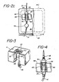
controller 20′ of FIGURE 2b theprecision control valve 22 of FIGURE 2a is replaced with a pump cassette which is in-line between thecommon tubing section 12 and theoutlet tubing section 14. A diaphragm on the back of the cassette is controllably moved in and out by a pump actuator extending from the front of the controller. This pump cassette and its operation are more particularly described in U.S. Patent Applications No. 902,616, filed September 2, 1986 and No. 25,681, filed March 13, 1987. - In the
controller 20˝ of FIGURE 2c the flow control mechanism shown is that used in the aforementioned U.S. Patent No. 4,576,592. In this arrangement adrip chamber 80 has acap 98 with an integrally molded drop former. Alip 94 at the bottom of the cap snaps into a retainingring 54 at the top of adrop detector 56. When the drip chamber is properly located within thedrop detector 56, its presence is detected by adoor 60 which is hinged as indicated at 63. Falling drops within the drip chamber are detected by the optical path indicated by the arrows at the top of the chamber and their passage is used by the primary controller to measure the flow of primary solution. Aprecision pinch valve 70 below thedrip chamber 80 selectively occludes theoutlet tubing 14 to regulate the flow of parenteral solution to the patient. When theprimary controller 20˝ of FIGURE 2c is used in the system of FIGURE 1, theprimary drip chamber 26 anddrop detector 4 can be dispensed with, as their function is provided by thedrop detector 56 anddrip chamber 80. - The
drop detector 4 and thedrip chamber 26 of FIGURE 1 are shown in detail in FIGURES 3 and 4. In FIGURE 3 thedrop detector 4 is seen to comprise a housing which encloses photodiodes and photodetectors for anoptical drop detector 62 and anoptical level detector 66. A spring hingeddoor 60 is located within the cavity in the center of the housing and projects forward in the absence of a drip chamber in the housing, in which position it blocks the optical path of thedrop detector 62. At the top of the housing is asplit mounting ring 54. - The
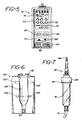
drop detector 4 is mounted about thedrip chamber 26 in FIGURE 4 by snapping thelip 94 of thespike 95 at the top of the chamber into the mountingring 54. Thespike 95 is inserted into a parenteral solution bag or membrane in the cap of the suspended fluid source prior to mounting the drop detector. When thedrip chamber 26 is properly engaged in the cavity of the drop detector housing, the chamber presses the hingeddoor 60 to the rear of the cavity, thereby unblocking the optical path of thedrop detector 62. The drop detector is able to sense the proper mounting of the drip chamber by the deflection of thedoor 60, and also senses proper priming of the drip chamber by the obscuring of thelevel detector 66 with fluid while the optics ofdrop detector 62 are unobscured. During normal operation, droplets will fall from the drop former and be detected by theoptical drop detector 62. A detailed description of thedrop detector 4 is presented in U.S. Patent Application SN 117,009, filed November 4, 1987. - The secondary infusion module of the present invention is shown in the front and back views of FIGURES 5 and 6. At the top of the
module 40 is adisplay 42, shown in FIGURE 5. A fivecharacter message center 72 is located at the top of the display. These fourteen segment characters display alarm and status conditions during the administration of the secondary solution. Below the message center is aninstrument logo design 74 which pulses during delivery of the secondary solution. Below the logo are threelarge characters 76 which display the flow rate of the solution. The descriptor "FLOW RATE" and the flow units of ml/hr are displayed above the flow rate numerals. Below the flow rate are three and one-half characters 78 which display the dose being administered, together with the descriptor "DOSE" and the units of ml. - Below the
display 42 are a series ofpushbuttons 44, which are used to program and operate themodule 40. The "SELECT"pushbutton 82 is depressed to program the module. When this pushbutton is depressed, the descriptor and units of the value being entered flash on the display, and the value is incremented or decremented by depressing the up/downpushbuttons 86. The "STANDBY"pushbutton 84 is depressed to stop the administration of the secondary solution and start the administration of the primary solution, or to clear the alarms on the secondary infusion module. Below thepushbuttons 86 is a "Load" key 88, which is depressed while mounting the secondary infusion module around the secondary drip chamber. An "Infuse" key 90 is depressed to begin the administration of the secondary solution. - The side of the secondary infusion module is shown in FIGURE 6. A
cavity 100 in the module is accessible from the side for insertion of the secondary drip chamber shown in FIGURE 7. At the top of the module is a mountingring 92, similar to the mountingring 54 of thedrop detector 4. The secondary infusion module is mounted around thesecondary drip chamber 81 by inserting thelip 94 of the drip chamber spike 95 into the mountingring 92. When so engaged, thedrip chamber 81 is positioned in the optical path of adrop detector low level detector barrier 93 must be withdrawn from the bottom of thecavity 100. The barrier is withdrawn by depressing the "Load" key, whereupon thetubing section 16 is located in the passage at the bottom of the cavity. When the "Load" key is released thebarrier 93 pinches thetubing section 16 closed. Fluid flow is thereby prevented until the "Infuse" key is depressed at the commencement of secondary infusion. - Control of the dual source infusion system of FIGURE 1 is provided by two microprocessors, one located in the primary controller and another in the secondary infusion module, as shown in block diagram form in FIGURE 8. The
microprocessor 200 in theprimary controller 20 interacts with other components of the primary controller as shown in the FIGURE. Themicroprocessor 200 activates and controls thedisplay 28 and analarm 208. It also controls amotor 204 for the pump or control valve, which in turn is connected to the pump or valve. Fault detector electronics 206 monitors the operation of the pump or valve and informs themicroprocessor 200 of the pump or valve operation. Faults detected by the electronics 206 are conditions related to flow, such as slow flow, no flow, or an occlusion at the infusion site. When any of these conditions are detected, themicroprocessor 200 will verify them and sound thealarm 208 and cease system operation until the alarm condition is remedied. - The
primary microprocessor 200 receives information on primary solution drop detection from theprimary drop detector 4 which indicate an alarm condition, such as high or low solution level in the primary drip chamber, no drops, or a continuous stream of drops. Whenever any of these conditions are detected themicroprocessor 200 will verify the problem, activate the alarm and cease system operation. - The
primary controller 20 is initially turned on by closure of the on/offswitch 132, which connects the microprocessor and other electronics to apower source 210. Themicroprocessor 200 also receives inputs from thestandby pushbutton 136, theSELECT pushbutton 134, the infusepushbutton 138, and the up/downpushbuttons 130. - In a similar manner the
microprocessor 300 in thesecondary infusion module 40 activates and controls thedisplay 42. Themicroprocessor 300 receives secondary solution drop detection information from the integralsecondary drop detector 102 andlevel detector 106, in particular drop detection and high or low level information, as well as notification that thedrip chamber 81 has been properly mounted. TheLoad key 88, theInfuse key 90, theSELECT pushbutton 82, theSTANDBY pushbutton 84, and the up/downpushbuttons 86 also are connected to provide inputs to themicroprocessor 300. - The two microprocessors are interconnected by a 6-
line communications bus 250, enclosed within thecable 34. The six lines include a transmit line, a receive line, a clock line, a VCC regulated voltage line, a Vbatt battery voltage line, and a ground line. During data transmission data words between the two microprocessors are sent and received by transceivers, one of which is located in theinterface 32 at the bottom of the primary controller. A second transceiver is located in thesecondary infusion module 40. Redundant transmissions are employed to assure data integrity. - An infusion procedure may be commenced using the system of the present invention by starting to administer the secondary solution first, then changing over to administration of the primary solution. One advantage of the arrangement of the present invention is that secondary solution administration can be commenced while the administration of primary solution is in progress, whereafter the system will revert back to primary solution administration when the administration of secondary solution is completed. Operation of the system of the present invention will be illustrated by explaining the latter process.
- To begin administration of a primary solution, the container is suspended from the pole, and the primary administration set (including
drip chamber 26,tubing section 8, check valve 6, Y-connector 10,tubing section 12,pinch valve 22, 79 orcassette 50, and tubing section 14) is connected to the solution container and primed with solution. With the administration set clamped shut the primary controller is programmed by entering values for the total dose in ml and the flow rate in ml/hr, using theSELECT pushbutton 134 and the up/downpushbuttons 130. As the values are entered they are verified visually on theprimary display 28. When the the primary solution values are properly entered the clamp on the tubing set is released and the infusepushbuttons 138 is depressed to begin infusion. Themicroprocessor 200 will thereupon execute a series of hardware and software checks to verify that the system is connected and operating properly, and will begin to control the pump or precision valve mechanism to adjust for the desired flow rate. As the infusion proceeds, information on the rate of progress is displayed on theprimary display 28. - The administration of primary solution may be interrupted by the administration of the secondary solution as follows. A hook which is a part of the secondary administration set is used to suspend the primary solution container from the pole at a level below that of the secondary solution container. The secondary solution container is suspended from the pole and the secondary administration set (including the
secondary drip chamber 81 and the tubing line 16) is connected to the container and primed with solution. Thetubing line 16 is clamped and a needle at the end oftubing section 16 is inserted into the Y-connector 10. Thesecondary infusion module 40 is mounted about thesecondary drip chamber 81 by inserting thedrip chamber 81 into the cavity at the side of the module while depressing then releasing the Load key. The module is then programmed for the values of secondary solution delivery by depressing theSELECT pushbutton 82 and the up/downpushbuttons 86. Entry of the correct values is visually confirmed by viewing thedisplay 42 on the module. The clamp on the administration set is released and delivery of the secondary solution begun by depressing the Infuse key on the module. - As soon as the secondary infusion module is connected to the primary controller, power is provided to the
module 40 from the primary controller and the microprocessors in the two units begin exchanging status bytes of information. During this period of initialization thesecondary microprocessor 300 executes a series of hardware and software checks to assure that the secondary system is connected and operating properly. Once the Infuse key has been depressed, an intense burst of communication between the two microprocessors begins. Themicroprocessor 300 sends a burst of twelve 8-bit bytes to themicroprocessor 200 over thecommunications bus 250. This data burst informs the primary controller as to the infusion parameters to be used for controlling the dose and flow rate. The received data is echoed back to the module for verification and the primary microprocessor begins to adjust the flow control mechanism for the proper rate of fluid delivery of the secondary solution. After the flow rate has been set, the two microprocessors resume exchanging status information at a low level. The primary controller sends eight-bit bytes to thesecondary microprocessor 300, each byte containing a "dose decrement" bit, a primary alarm bit, a "stop infuse" bit, and an unused bit. These four bits are repeated in the last four bits of the byte for redundancy checking. Delivery of the secondary solution commences as the pressure head of the secondary solutions closes the check valve 6 and the secondary solution flows into the pump or control valve mechanism. - During delivery of the secondary solution the
microprocessor 300 monitors the drop formation and fluid level in thesecondary drip chamber 81. Every eight milliseconds thesecondary microprocessor 81 transmits an 8-bit status byte to the primary microprocessor. Each byte contains an alarm bit, a drop sense bit, a start/stop bit, and a level bit. These four bits are replicated in the second four bits of the byte for redundancy. Whenever a falling drop is detected in the secondary drip chamber the drop sense bit is set in the transmitted byte, and held for 100 milliseconds for debounce purposes. The start/stop bit is set and held after the Infuse key is depressed, and is released only when secondary infusion is completed. When this bit is released, the secondary infusion module is shut down and the infusion of primary solution resumes. The other bits in the status byte, including the alarm bit and the level bit, are checked by theprimary microprocessor 200 every 72 milliseconds. The level bit is set if the secondary microprocessor detects the presence of fluid at the level ofdetector secondary drip chamber 81. This may or may not be an error condition, depending upon the status of the drop sense bit: if both bits are set for 100 msec, a falling drop has been detected; if both bits remain set for more than two seconds, the drip chamber is filled with solution and an alarm occurs; if both bits are not set, ther is a low solution level in the drip chamber and the module will continue to await the detection of a falling droplet; if the level bit is not set and the drop sense bit is intermittent, drops are occurring in an insufficiently filled drip chamber; if the level bit is not set and the drop sense bit is continuously set there is no drip chamber in themodule 40; and if the level bit is continuously set and the drop sense bit is continuously not set, thedrip chamber 81 and secondary administration set are primed and awaiting the infuse command. - When a secondary drip chamber fault is detected, the alarm on the primary controller sounds, the system shuts down, and the primary controller displays "SECONDRY" on its message center. The exact type of fault is displayed on the secondary infusion module's message center. A flow-related error would be detected by the primary controller, since the primary controller is operating and monitoring the flow-regulating mechanism. When a flow-related error is detected, the system is shut down as the alarm sounds, and the error type is displayed on the message center of the primary controller.
- When the secondary infusion module is delivering the secondary solution, either after interrupting primary solution delivery or by starting the system with initial delivery of the secondary solution, there are several ways of terminating secondary solution delivery. One way is to deliver the programmed dose of secondary solution, whereupon system operation switches over from the secondary module to the primary controller. It is possible to deliver not just a measured dose, but the entire supply of secondary solution. The module is programmed to do this by decrementing from a dose of "000" using the up/down keys, whereupon the dose display reads "ALL." The delivery of the full supply of solution is detected by a low level detection in the secondary drip chamber.
- There are also three types of alarm conditions which will terminate secondary solution delivery. One is an error condition in the secondary drip chamber, which is detected by the secondary module and communicated to the primary controller. A second type, as mentioned above, is a flow-related error which is detected by the primary controller. The third type of error is a hardware or software malfunction or communication link problem, which may be detected by either the primary controller or the secondary module.
- Finally, it is possible to stop secondary solution delivery by depressing the STANDBY pushbuttons 84 or 136. This will stop the delivery of the secondary solution and switch the system over to the delivery of the primary solution. The
STANDBY pushbutton 84 is also depressed following a secondary error detection to clear the secondary alarm state as the error condition is remedied. Secondary solution delivery may be restarted after the STANDBY pushbutton is activated by again depressing the Infuse key. - The dual source infusion system of FIGURE 1 may be operated by first suspending the solution containers from the pole. The primary administration set is connected to the primary solution container and is primed with solution and clamped. The secondary administration set is connected to the secondary solution container, primed, clamped, and connected to the Y-connector of the primary administration set. The
primary controller 20 is programmed for delivery of the primary solution by entering the flow rate, dose, and any other information necessary such as the fluid code. As these values are programmed into the controller with thepushbuttons 30 they may be visually verified on thedisplay 28. Thesecondary infusion module 40 is then programmed for delivery of the secondary solution using thepushbuttons 44 on the module. The values for the dose and flow rate of the secondary solution can be observed directly on themodule display 42 as they are entered. When both units are programmed the delivery of the secondary solution is commenced by depressing the Infuse key. As fluid delivery continues, the progress of secondary fluid delivery can be seen immediately on themodule display 42, and the programmed values for the primary solution can be checked by viewing them on theprimary controller display 28. When the programmed dose of secondary solution has been delivered, the total volume of solution delivered can be viewed on the controller display and the volume of primary solution remaining to be delivered can be simultaneously viewed on the controller display. Information as to the delivery of both solutions is thus readily and unambiguously apparent to the user without any manipulation of either the module or the controller.
Claims (17)
a source of primary parenteral solution;
a source of secondary parenteral solution;
a primary administration set connected to said primary solution source, including a Y-connector and a section of control tubing;
a secondary administration set connected to said secondary solution source and to said Y-connector and including a secondary drip chamber;
a primary controller, including flow control means connected to said common tubing, means for detecting the delivery of primary solution, a display for displaying fluid delivery parameters, and means for programming said controller with fluid delivery parameters; and
a secondary infusion module communicating with said primary controller, operating in conjunction with said secondary drip chamber, and associated with said secondary administration set, and including a display for displaying fluid delivery parameters of said secondary solution.
a secondary infusion module associated with said secondary administration set and communicating with said controller, said module including means for detecting the delivery of said secondary solution and means for displaying parameters associated with the delivery of said secondary solution.
wherein said delivered dose information is displayed on said displaying means.
Priority Applications (1)
| Application Number | Priority Date | Filing Date | Title |
|---|---|---|---|
| AT89308227T ATE90210T1 (en) | 1988-08-15 | 1989-08-14 | DUAL FLUID LINE PARENTERAL INFUSION SYSTEM WITH SECONDARY INFUSION MODULE. |
Applications Claiming Priority (2)
| Application Number | Priority Date | Filing Date | Title |
|---|---|---|---|
| US232058 | 1988-08-15 | ||
| US07/232,058 US4946439A (en) | 1988-08-15 | 1988-08-15 | Dual source parenteral infusion system with secondary infusion module |
Publications (2)
| Publication Number | Publication Date |
|---|---|
| EP0361662A1 true EP0361662A1 (en) | 1990-04-04 |
| EP0361662B1 EP0361662B1 (en) | 1993-06-09 |
Family
ID=22871706
Family Applications (1)
| Application Number | Title | Priority Date | Filing Date |
|---|---|---|---|
| EP89308227A Expired - Lifetime EP0361662B1 (en) | 1988-08-15 | 1989-08-14 | Dual source parenteral infusion system with secondary infusion module |
Country Status (13)
| Country | Link |
|---|---|
| US (1) | US4946439A (en) |
| EP (1) | EP0361662B1 (en) |
| JP (1) | JPH02161955A (en) |
| KR (1) | KR900002807A (en) |
| CN (1) | CN1021799C (en) |
| AT (1) | ATE90210T1 (en) |
| AU (1) | AU614409B2 (en) |
| BR (1) | BR8904093A (en) |
| CA (1) | CA1310555C (en) |
| MX (1) | MX169387B (en) |
| NZ (1) | NZ230254A (en) |
| PT (1) | PT91449B (en) |
| ZA (1) | ZA896185B (en) |
Cited By (10)
| Publication number | Priority date | Publication date | Assignee | Title |
|---|---|---|---|---|
| EP0456871A1 (en) * | 1990-05-18 | 1991-11-21 | Clinico Medical Electronics GmbH | Device and procedure to determine and regulate the number of drops passing a drip chamber |
| GB2257364A (en) * | 1991-05-07 | 1993-01-13 | Imed Corp | Pumping system for intravenous administration of a secondary treatment fluid |
| DE4320365A1 (en) * | 1993-06-19 | 1994-12-22 | Draegerwerk Ag | Multi-channel dosing system |
| EP0658354A1 (en) * | 1993-11-23 | 1995-06-21 | Fresenius AG | Metering device for volumetric dispensing of a liquid additive |
| WO1996027399A1 (en) * | 1995-03-06 | 1996-09-12 | Isprobi S.R.L. | Device of the controlled injection of a programmable quantity of liquid |
| US6063052A (en) * | 1993-10-28 | 2000-05-16 | Medrad, Inc. | Injection system and pumping system for use therein |
| WO2005065751A1 (en) * | 2003-12-31 | 2005-07-21 | Cardinal Health 303, Inc. | Medication safety enhancement for secondary infusion |
| WO2010090858A3 (en) * | 2009-01-21 | 2010-09-23 | Medtronic, Inc. | Catheter systems having flow restrictors |
| CN102125709A (en) * | 2011-04-18 | 2011-07-20 | 泉州市银星电子科技有限公司 | Method for controlling dropping speed of liquid drops of automatic infusion pump |
| US9539382B2 (en) | 2013-03-12 | 2017-01-10 | Medtronic, Inc. | Stepped catheters with flow restrictors and infusion systems using the same |
Families Citing this family (159)
| Publication number | Priority date | Publication date | Assignee | Title |
|---|---|---|---|---|
| US5322506A (en) * | 1989-07-31 | 1994-06-21 | C. R. Bard, Inc. | Irrigation system with high flow bypass for use with endoscopic procedure |
| US5116312A (en) * | 1989-11-03 | 1992-05-26 | The Uab Research Foundation | Method and apparatus for automatic autotransfusion |
| WO1991009636A1 (en) * | 1989-12-28 | 1991-07-11 | Kent Archibald G | Spring powered flow rate iv controller |
| US5250027A (en) * | 1991-10-08 | 1993-10-05 | Sherwood Medical Company | Peristaltic infusion device with backpack sensor |
| US5169028A (en) * | 1991-06-25 | 1992-12-08 | Advanced Micro Devices, Inc. | Phatoresist dispensing system |
| US5277175A (en) * | 1991-07-12 | 1994-01-11 | Riggs John H | Continuous flow nebulizer apparatus and method, having means maintaining a constant-level reservoir |
| KR930003929A (en) * | 1991-08-23 | 1993-03-22 | 겐시로 오가와 | Sap volume control device |
| US5621392A (en) * | 1991-11-05 | 1997-04-15 | Hospal Ltd. | Flow detector |
| US5195967A (en) * | 1992-02-18 | 1993-03-23 | Nakao Naomi L | Anticlotting device and method for use with IV catheters |
| US5355872B1 (en) * | 1992-03-04 | 1998-10-20 | John H Riggs | Low flow rate nebulizer apparatus and method of nebulization |
| ATE170084T1 (en) * | 1992-04-15 | 1998-09-15 | Hill Rom Co Inc | HOLDER FOR AN INTRAVENOUS INFUSION SYSTEM |
| US5578005A (en) * | 1993-08-06 | 1996-11-26 | River Medical, Inc. | Apparatus and methods for multiple fluid infusion |
| DE69432582T2 (en) * | 1993-10-28 | 2003-11-27 | Medrad Inc | System for the administration of liquids in several patients |
| DE1258262T1 (en) | 1993-10-28 | 2003-04-10 | Medrad Inc | Contrast delivery system |
| US5569181A (en) * | 1993-10-28 | 1996-10-29 | Medrad, Inc. | Sterility assurance for contrast delivery system |
| DE69526613T2 (en) * | 1994-07-12 | 2002-08-29 | Medrad Inc | Information path control loop for a system that delivers medical fluids |
| US5840026A (en) | 1994-09-21 | 1998-11-24 | Medrad, Inc. | Patient specific dosing contrast delivery systems and methods |
| US5772635A (en) * | 1995-05-15 | 1998-06-30 | Alaris Medical Systems, Inc. | Automated infusion system with dose rate calculator |
| US5898961A (en) * | 1995-06-07 | 1999-05-04 | Hill-Rom, Inc. | Mobile support unit and attachment mechanism for patient transport device |
| US5807321A (en) * | 1995-11-28 | 1998-09-15 | Merit Medical | System for electronically monitoring the delivery of contrast media |
| US5745378A (en) * | 1995-12-04 | 1998-04-28 | Abbott Laboratories | Parameter input for drug delivery pump |
| US5782805A (en) * | 1996-04-10 | 1998-07-21 | Meinzer; Randolph | Medical infusion pump |
| US5807313A (en) * | 1996-07-19 | 1998-09-15 | C. R. Bard, Inc. | Battery powered surgical irrigator |
| US5814009A (en) * | 1996-10-11 | 1998-09-29 | Cabot Technology Corporation | Fluid management system and replaceable tubing assembly therefor |
| IL120654A (en) * | 1997-04-11 | 2001-08-08 | Nestle Sa | Administration of two liquids to a patient |
| USD409748S (en) * | 1997-08-22 | 1999-05-11 | Deka Products Limited Partnership | Disposable cassette for bedside pharmacy system |
| US6884230B1 (en) * | 1998-03-09 | 2005-04-26 | Baxter International Inc. | Dispensing head for a tissue sealant applicator and process of use |
| US6071269A (en) * | 1998-05-13 | 2000-06-06 | Medisystems Technology Corporation | Blood set and chamber |
| US6921380B1 (en) | 1998-10-01 | 2005-07-26 | Baxter International Inc. | Component mixing catheter |
| IL128056A (en) * | 1999-01-14 | 2005-11-20 | S F M Sophisticated Water Mete | Liquid metering device |
| DE20008961U1 (en) * | 2000-05-18 | 2001-09-27 | Braun Melsungen Ag | Infusion pump |
| WO2003006101A2 (en) * | 2001-07-10 | 2003-01-23 | Medrad, Inc. | Devices, systems and method for infusion of fluids |
| US7109974B2 (en) * | 2002-03-05 | 2006-09-19 | Matsushita Electric Industrial Co., Ltd. | Remote control system including an on-screen display (OSD) |
| DE60336724D1 (en) | 2002-07-19 | 2011-05-26 | Baxter Healthcare Sa | SYSTEM FOR PERITONEAL DIALYSIS |
| US9135402B2 (en) | 2007-12-17 | 2015-09-15 | Dexcom, Inc. | Systems and methods for processing sensor data |
| US7591801B2 (en) | 2004-02-26 | 2009-09-22 | Dexcom, Inc. | Integrated delivery device for continuous glucose sensor |
| US8886273B2 (en) | 2003-08-01 | 2014-11-11 | Dexcom, Inc. | Analyte sensor |
| US8626257B2 (en) | 2003-08-01 | 2014-01-07 | Dexcom, Inc. | Analyte sensor |
| US20190357827A1 (en) | 2003-08-01 | 2019-11-28 | Dexcom, Inc. | Analyte sensor |
| US7920906B2 (en) | 2005-03-10 | 2011-04-05 | Dexcom, Inc. | System and methods for processing analyte sensor data for sensor calibration |
| US8065161B2 (en) | 2003-11-13 | 2011-11-22 | Hospira, Inc. | System for maintaining drug information and communicating with medication delivery devices |
| US9123077B2 (en) | 2003-10-07 | 2015-09-01 | Hospira, Inc. | Medication management system |
| US9247900B2 (en) | 2004-07-13 | 2016-02-02 | Dexcom, Inc. | Analyte sensor |
| US8425417B2 (en) | 2003-12-05 | 2013-04-23 | Dexcom, Inc. | Integrated device for continuous in vivo analyte detection and simultaneous control of an infusion device |
| US11633133B2 (en) | 2003-12-05 | 2023-04-25 | Dexcom, Inc. | Dual electrode system for a continuous analyte sensor |
| US8423114B2 (en) | 2006-10-04 | 2013-04-16 | Dexcom, Inc. | Dual electrode system for a continuous analyte sensor |
| US8532730B2 (en) | 2006-10-04 | 2013-09-10 | Dexcom, Inc. | Analyte sensor |
| US8425416B2 (en) | 2006-10-04 | 2013-04-23 | Dexcom, Inc. | Analyte sensor |
| US8364230B2 (en) | 2006-10-04 | 2013-01-29 | Dexcom, Inc. | Analyte sensor |
| US8364231B2 (en) | 2006-10-04 | 2013-01-29 | Dexcom, Inc. | Analyte sensor |
| US8287453B2 (en) | 2003-12-05 | 2012-10-16 | Dexcom, Inc. | Analyte sensor |
| US7206715B2 (en) * | 2003-12-31 | 2007-04-17 | Cardinal Health 303, Inc. | Empty container detection using container side pressure sensing |
| US7255683B2 (en) * | 2003-12-31 | 2007-08-14 | Cardinal Health 303, Inc. | System for detecting the status of a vent associated with a fluid supply upstream of an infusion pump |
| US8808228B2 (en) | 2004-02-26 | 2014-08-19 | Dexcom, Inc. | Integrated medicament delivery device for use with continuous analyte sensor |
| US7946984B2 (en) | 2004-07-13 | 2011-05-24 | Dexcom, Inc. | Transcutaneous analyte sensor |
| US8886272B2 (en) | 2004-07-13 | 2014-11-11 | Dexcom, Inc. | Analyte sensor |
| US7783333B2 (en) | 2004-07-13 | 2010-08-24 | Dexcom, Inc. | Transcutaneous medical device with variable stiffness |
| WO2006055813A2 (en) | 2004-11-16 | 2006-05-26 | Medrad, Inc. | Modeling of pharmaceutical propagation |
| EP2990073B1 (en) | 2004-11-24 | 2018-05-02 | Bayer Healthcare LLC | Devices and systems for fluid delivery |
| IL166400A (en) * | 2005-01-20 | 2012-07-31 | Flowsense Ltd | Optical drop detection system |
| US20080097389A1 (en) * | 2006-07-10 | 2008-04-24 | Wilson Roland B | Y-type blood transfusion set |
| US8449464B2 (en) | 2006-10-04 | 2013-05-28 | Dexcom, Inc. | Analyte sensor |
| US8478377B2 (en) | 2006-10-04 | 2013-07-02 | Dexcom, Inc. | Analyte sensor |
| US8298142B2 (en) | 2006-10-04 | 2012-10-30 | Dexcom, Inc. | Analyte sensor |
| US8275438B2 (en) | 2006-10-04 | 2012-09-25 | Dexcom, Inc. | Analyte sensor |
| US8447376B2 (en) | 2006-10-04 | 2013-05-21 | Dexcom, Inc. | Analyte sensor |
| US8562528B2 (en) | 2006-10-04 | 2013-10-22 | Dexcom, Inc. | Analyte sensor |
| EP2092470A2 (en) | 2006-10-16 | 2009-08-26 | Hospira, Inc. | System and method for comparing and utilizing activity information and configuration information from mulitple device management systems |
| US7934498B1 (en) | 2006-11-13 | 2011-05-03 | Robert Heidelberger | Device and method for facilitating delivery of medication/humidity to a patient without breaking a ventilator circuit |
| AU2007320718A1 (en) * | 2006-11-14 | 2008-05-22 | Flowsense Ltd | A diagnostic method and apparatus |
| WO2008085421A2 (en) | 2006-12-29 | 2008-07-17 | Medrad, Inc. | Patient-based parameter generation systems for medical injection procedures |
| WO2008154312A1 (en) | 2007-06-08 | 2008-12-18 | Dexcom, Inc. | Integrated medicament delivery device for use with continuous analyte sensor |
| CN103976736B (en) | 2007-07-17 | 2017-01-11 | 拜耳医药保健有限责任公司 | Devices and systems for determination of parameters for a procedure, for estimation of cardiopulmonary function and for fluid delivery |
| IL185477A0 (en) | 2007-08-23 | 2008-01-06 | Med I Dynamix Fluid Monitoring | Diagnostic methods and systems based on urine analysis |
| US7871462B2 (en) * | 2007-10-01 | 2011-01-18 | Baxter International Inc. | Dialysis systems having air separation chambers with internal structures to enhance air removal |
| US8444587B2 (en) | 2007-10-01 | 2013-05-21 | Baxter International Inc. | Fluid and air handling in blood and dialysis circuits |
| US7892332B2 (en) * | 2007-10-01 | 2011-02-22 | Baxter International Inc. | Dialysis systems having air traps with internal structures to enhance air removal |
| US7892331B2 (en) * | 2007-10-01 | 2011-02-22 | Baxter International Inc. | Dialysis systems having air separation chambers with internal structures to enhance air removal |
| US9452258B2 (en) | 2007-10-09 | 2016-09-27 | Dexcom, Inc. | Integrated insulin delivery system with continuous glucose sensor |
| US8123947B2 (en) | 2007-10-22 | 2012-02-28 | Baxter International Inc. | Priming and air removal systems and methods for dialysis |
| US8114276B2 (en) | 2007-10-24 | 2012-02-14 | Baxter International Inc. | Personal hemodialysis system |
| US8417312B2 (en) | 2007-10-25 | 2013-04-09 | Dexcom, Inc. | Systems and methods for processing sensor data |
| US8290559B2 (en) | 2007-12-17 | 2012-10-16 | Dexcom, Inc. | Systems and methods for processing sensor data |
| US9026370B2 (en) * | 2007-12-18 | 2015-05-05 | Hospira, Inc. | User interface improvements for medical devices |
| WO2009105709A1 (en) | 2008-02-21 | 2009-08-27 | Dexcom, Inc. | Systems and methods for processing, transmitting and displaying sensor data |
| US8608484B2 (en) * | 2008-03-04 | 2013-12-17 | Medrad, Inc. | Dynamic anthropomorphic cardiovascular phantom |
| US8396528B2 (en) | 2008-03-25 | 2013-03-12 | Dexcom, Inc. | Analyte sensor |
| US8315449B2 (en) | 2008-06-24 | 2012-11-20 | Medrad, Inc. | Identification of regions of interest and extraction of time value curves in imaging procedures |
| US8057679B2 (en) | 2008-07-09 | 2011-11-15 | Baxter International Inc. | Dialysis system having trending and alert generation |
| US9421330B2 (en) | 2008-11-03 | 2016-08-23 | Bayer Healthcare Llc | Mitigation of contrast-induced nephropathy |
| US8315885B2 (en) | 2009-04-14 | 2012-11-20 | Baxter International Inc. | Therapy management development platform |
| US8271106B2 (en) | 2009-04-17 | 2012-09-18 | Hospira, Inc. | System and method for configuring a rule set for medical event management and responses |
| MX337978B (en) | 2009-07-01 | 2016-03-29 | Fresenius Med Care Hldg Inc | Drug delivery devices and related systems and methods. |
| CA2803169C (en) | 2010-06-24 | 2020-09-22 | Medrad, Inc. | Modeling of pharmaceutical propagation and parameter generation for injection protocols |
| CN101972504B (en) * | 2010-11-09 | 2012-11-21 | 衣启武 | Vein continuous infusion intelligent controller and application method thereof |
| US8382711B2 (en) | 2010-12-29 | 2013-02-26 | Baxter International Inc. | Intravenous pumping air management systems and methods |
| US10064987B2 (en) | 2011-01-31 | 2018-09-04 | Fresenius Medical Care Holdings, Inc. | Preventing over-delivery of drug |
| US9987406B2 (en) | 2011-02-08 | 2018-06-05 | Fresenius Medical Care Holdings, Inc. | Magnetic sensors and related systems and methods |
| DK3575796T3 (en) | 2011-04-15 | 2021-01-18 | Dexcom Inc | ADVANCED ANALYZE SENSOR CALIBRATION AND ERROR DETECTION |
| US9240002B2 (en) | 2011-08-19 | 2016-01-19 | Hospira, Inc. | Systems and methods for a graphical interface including a graphical representation of medical data |
| WO2013043889A1 (en) | 2011-09-21 | 2013-03-28 | Medrad, Inc. | System and assembly method for a fluid pump device for a continuous multi-fluid delivery system |
| ES2959510T3 (en) | 2011-10-21 | 2024-02-26 | Icu Medical Inc | Medical device update system |
| US10022498B2 (en) | 2011-12-16 | 2018-07-17 | Icu Medical, Inc. | System for monitoring and delivering medication to a patient and method of using the same to minimize the risks associated with automated therapy |
| US20130226066A1 (en) * | 2012-02-23 | 2013-08-29 | Jung-Tung Liu | Apparatus for monitoring cerebrospinal fluid drainage |
| ES2741725T3 (en) | 2012-03-30 | 2020-02-12 | Icu Medical Inc | Air detection system and method to detect air in a pump of an infusion system |
| US9144646B2 (en) | 2012-04-25 | 2015-09-29 | Fresenius Medical Care Holdings, Inc. | Vial spiking devices and related assemblies and methods |
| HUE056182T2 (en) | 2012-05-14 | 2022-01-28 | Bayer Healthcare Llc | Systems and methods for determination of pharmaceutical fluid injection protocols based on x-ray tube voltage |
| US9205187B2 (en) | 2012-06-12 | 2015-12-08 | Carefusion 303, Inc. | Managing a fluid flow |
| ES2743160T3 (en) | 2012-07-31 | 2020-02-18 | Icu Medical Inc | Patient care system for critical medications |
| AU2014225658B2 (en) | 2013-03-06 | 2018-05-31 | Icu Medical, Inc. | Medical device communication method |
| US9555379B2 (en) | 2013-03-13 | 2017-01-31 | Bayer Healthcare Llc | Fluid path set with turbulent mixing chamber, backflow compensator |
| WO2014149013A2 (en) * | 2013-03-22 | 2014-09-25 | Özel Erkan | An infusion set that operates with an infusion pump, which restrains the flow of air from the serum set to the patient and prevents said air to mix with ambient air |
| AU2014268355B2 (en) | 2013-05-24 | 2018-06-14 | Icu Medical, Inc. | Multi-sensor infusion system for detecting air or an occlusion in the infusion system |
| AU2014274146B2 (en) | 2013-05-29 | 2019-01-24 | Icu Medical, Inc. | Infusion system which utilizes one or more sensors and additional information to make an air determination regarding the infusion system |
| WO2014194065A1 (en) | 2013-05-29 | 2014-12-04 | Hospira, Inc. | Infusion system and method of use which prevents over-saturation of an analog-to-digital converter |
| JP6621748B2 (en) | 2013-08-30 | 2019-12-18 | アイシーユー・メディカル・インコーポレーテッド | System and method for monitoring and managing a remote infusion regimen |
| US9662436B2 (en) | 2013-09-20 | 2017-05-30 | Icu Medical, Inc. | Fail-safe drug infusion therapy system |
| US10311972B2 (en) | 2013-11-11 | 2019-06-04 | Icu Medical, Inc. | Medical device system performance index |
| WO2015077320A1 (en) | 2013-11-19 | 2015-05-28 | Hospira, Inc. | Infusion pump automation system and method |
| JP6636442B2 (en) | 2014-02-28 | 2020-01-29 | アイシーユー・メディカル・インコーポレーテッド | Infusion systems and methods utilizing dual wavelength optical in-pipe air detection |
| JP6853669B2 (en) | 2014-04-30 | 2021-03-31 | アイシーユー・メディカル・インコーポレーテッド | Patient treatment system with conditional alert forwarding |
| JP2017517302A (en) | 2014-05-29 | 2017-06-29 | ホスピーラ インコーポレイテッド | Infusion system and pump with configurable closed loop delivery rate catchup |
| US9724470B2 (en) | 2014-06-16 | 2017-08-08 | Icu Medical, Inc. | System for monitoring and delivering medication to a patient and method of using the same to minimize the risks associated with automated therapy |
| US9539383B2 (en) | 2014-09-15 | 2017-01-10 | Hospira, Inc. | System and method that matches delayed infusion auto-programs with manually entered infusion programs and analyzes differences therein |
| US9486590B2 (en) | 2014-09-29 | 2016-11-08 | Fenwal, Inc. | Automatic purging of air from a fluid processing system |
| US11344668B2 (en) | 2014-12-19 | 2022-05-31 | Icu Medical, Inc. | Infusion system with concurrent TPN/insulin infusion |
| EP3242649A4 (en) | 2015-01-09 | 2019-01-09 | Bayer Healthcare LLC | Multiple fluid delivery system with multi-use disposable set and features thereof |
| US10850024B2 (en) | 2015-03-02 | 2020-12-01 | Icu Medical, Inc. | Infusion system, device, and method having advanced infusion features |
| WO2016189417A1 (en) | 2015-05-26 | 2016-12-01 | Hospira, Inc. | Infusion pump system and method with multiple drug library editor source capability |
| CA2985719C (en) | 2015-06-25 | 2024-03-26 | Gambro Lundia Ab | Medical device system and method having a distributed database |
| US10625009B2 (en) | 2016-02-17 | 2020-04-21 | Baxter International Inc. | Airtrap, system and method for removing microbubbles from a fluid stream |
| WO2017152036A1 (en) | 2016-03-03 | 2017-09-08 | Bayer Healthcare Llc | System and method for improved fluid delivery in multi-fluid injector systems |
| EP4085944A1 (en) | 2016-05-13 | 2022-11-09 | ICU Medical, Inc. | Infusion pump system with common line auto flush |
| US11324888B2 (en) | 2016-06-10 | 2022-05-10 | Icu Medical, Inc. | Acoustic flow sensor for continuous medication flow measurements and feedback control of infusion |
| EP3484541A4 (en) | 2016-07-14 | 2020-03-25 | ICU Medical, Inc. | Multi-communication path selection and security system for a medical device |
| US11141529B2 (en) * | 2016-10-17 | 2021-10-12 | Jms Co., Ltd. | Infusion apparatus |
| WO2018114346A1 (en) | 2016-12-21 | 2018-06-28 | Gambro Lundia Ab | Medical device system including information technology infrastructure having secure cluster domain supporting external domain |
| CN110809482B (en) | 2017-08-31 | 2023-03-07 | 拜耳医药保健有限公司 | Fluid injector system volume compensation system and method |
| EP3675930B1 (en) | 2017-08-31 | 2024-01-17 | Bayer Healthcare LLC | Method for drive member position and fluid injector system mechanical calibration |
| AU2018326485B2 (en) | 2017-08-31 | 2024-01-04 | Bayer Healthcare Llc | Injector pressure calibration system and method |
| US11141535B2 (en) | 2017-08-31 | 2021-10-12 | Bayer Healthcare Llc | Fluid path impedance assessment for improving fluid delivery performance |
| US11779702B2 (en) | 2017-08-31 | 2023-10-10 | Bayer Healthcare Llc | Method for dynamic pressure control in a fluid injector system |
| CN107715237A (en) * | 2017-10-23 | 2018-02-23 | 陈丽曼 | Infusion monitoring warning system |
| US20190120785A1 (en) | 2017-10-24 | 2019-04-25 | Dexcom, Inc. | Pre-connected analyte sensors |
| US11331022B2 (en) | 2017-10-24 | 2022-05-17 | Dexcom, Inc. | Pre-connected analyte sensors |
| US10089055B1 (en) | 2017-12-27 | 2018-10-02 | Icu Medical, Inc. | Synchronized display of screen content on networked devices |
| CN108671318A (en) * | 2018-07-10 | 2018-10-19 | 上海交通大学医学院附属第九人民医院 | A kind of medical transfusion changing liquid automatically and warning system |
| NZ771914A (en) | 2018-07-17 | 2023-04-28 | Icu Medical Inc | Updating infusion pump drug libraries and operational software in a networked environment |
| EP3824383B1 (en) | 2018-07-17 | 2023-10-11 | ICU Medical, Inc. | Systems and methods for facilitating clinical messaging in a network environment |
| US11139058B2 (en) | 2018-07-17 | 2021-10-05 | Icu Medical, Inc. | Reducing file transfer between cloud environment and infusion pumps |
| US10950339B2 (en) | 2018-07-17 | 2021-03-16 | Icu Medical, Inc. | Converting pump messages in new pump protocol to standardized dataset messages |
| AU2019309766A1 (en) | 2018-07-26 | 2021-03-18 | Icu Medical, Inc. | Drug library management system |
| US10692595B2 (en) | 2018-07-26 | 2020-06-23 | Icu Medical, Inc. | Drug library dynamic version management |
| CN109821111A (en) * | 2019-03-20 | 2019-05-31 | 王雨欣 | Infusion continues bottle warning device automatically |
| US11278671B2 (en) | 2019-12-04 | 2022-03-22 | Icu Medical, Inc. | Infusion pump with safety sequence keypad |
| CA3189781A1 (en) | 2020-07-21 | 2022-01-27 | Icu Medical, Inc. | Fluid transfer devices and methods of use |
| CN111840691A (en) * | 2020-07-21 | 2020-10-30 | 广东医科大学 | Liquid medicine conveying box for intensive care unit |
| CN112675381B (en) * | 2020-12-01 | 2022-06-03 | 河南职业技术学院 | Adjustable intelligent infusion robot based on Internet of things |
| US11135360B1 (en) | 2020-12-07 | 2021-10-05 | Icu Medical, Inc. | Concurrent infusion with common line auto flush |
Citations (9)
| Publication number | Priority date | Publication date | Assignee | Title |
|---|---|---|---|---|
| US4367817A (en) * | 1980-02-22 | 1983-01-11 | Satake Engineering Co., Ltd. | Color discriminating machine |
| US4451255A (en) * | 1982-05-20 | 1984-05-29 | Abbott Laboratories | Dual flow rate intravenous administration set with single pump chamber |
| US4507112A (en) * | 1982-04-05 | 1985-03-26 | Ipco Corporation | Infusion monitor |
| US4533347A (en) * | 1983-12-19 | 1985-08-06 | Warner-Lambert Company | Controller for a dual drug delivery system |
| EP0154163A2 (en) * | 1984-02-07 | 1985-09-11 | Critikon GmbH | Control apparatus for infusion by gravity |
| US4553958A (en) * | 1983-02-04 | 1985-11-19 | Quest Medical, Inc. | IV Delivery controller |
| US4576592A (en) * | 1983-03-30 | 1986-03-18 | Anatros Corporation | Dual source parenteral infusion apparatus |
| EP0189491A1 (en) * | 1983-08-19 | 1986-08-06 | Intermedicat Gmbh | Device for dosed simultaneous infusing solutions |
| EP0233115A1 (en) * | 1986-02-03 | 1987-08-19 | Bertin & Cie | System for the remote monitoring of at least one infusion station |
Family Cites Families (10)
| Publication number | Priority date | Publication date | Assignee | Title |
|---|---|---|---|---|
| US3886937A (en) * | 1971-02-12 | 1975-06-03 | American Hospital Supply Corp | Medical administration set for dispensing plural medical liquids |
| US3982534A (en) * | 1975-01-10 | 1976-09-28 | Buckman Thomas P | Intravenous administration system |
| US4094318A (en) * | 1976-07-09 | 1978-06-13 | Burron Medical Products, Inc. | Electronic control means for a plurality of intravenous infusion sets |
| US4114617A (en) * | 1977-02-28 | 1978-09-19 | Turner Thomas D | Apparatus for infusion of a measured volume of blood |
| US4300552A (en) * | 1978-09-01 | 1981-11-17 | Imed Corporation | Apparatus for controlling the flow of intravenous fluid to a patient |
| US4314567A (en) * | 1979-09-24 | 1982-02-09 | Imed Corporation | Drop controller |
| US4553347A (en) * | 1984-06-25 | 1985-11-19 | Jackson Francis J | Gun trigger actuator |
| US4673389A (en) * | 1984-11-29 | 1987-06-16 | Minnesota Mining And Manufacturing Company | Sequence valve for piggyback IV administration |
| US4821028A (en) * | 1985-04-26 | 1989-04-11 | Centaur Sciences, Inc. | Flow control system |
| US4710166A (en) * | 1985-11-08 | 1987-12-01 | Quest Medical, Inc. | Automated drug additive infusion system |
-
1988
- 1988-08-15 US US07/232,058 patent/US4946439A/en not_active Expired - Fee Related
-
1989
- 1989-08-08 NZ NZ230254A patent/NZ230254A/en unknown
- 1989-08-11 AU AU39543/89A patent/AU614409B2/en not_active Ceased
- 1989-08-11 CA CA000608139A patent/CA1310555C/en not_active Expired - Lifetime
- 1989-08-14 KR KR1019890011567A patent/KR900002807A/en not_active Application Discontinuation
- 1989-08-14 PT PT91449A patent/PT91449B/en not_active IP Right Cessation
- 1989-08-14 ZA ZA896185A patent/ZA896185B/en unknown
- 1989-08-14 EP EP89308227A patent/EP0361662B1/en not_active Expired - Lifetime
- 1989-08-14 AT AT89308227T patent/ATE90210T1/en not_active IP Right Cessation
- 1989-08-15 MX MX017204A patent/MX169387B/en unknown
- 1989-08-15 BR BR898904093A patent/BR8904093A/en not_active Application Discontinuation
- 1989-08-15 CN CN89107599A patent/CN1021799C/en not_active Expired - Fee Related
- 1989-08-15 JP JP1209723A patent/JPH02161955A/en active Pending
Patent Citations (9)
| Publication number | Priority date | Publication date | Assignee | Title |
|---|---|---|---|---|
| US4367817A (en) * | 1980-02-22 | 1983-01-11 | Satake Engineering Co., Ltd. | Color discriminating machine |
| US4507112A (en) * | 1982-04-05 | 1985-03-26 | Ipco Corporation | Infusion monitor |
| US4451255A (en) * | 1982-05-20 | 1984-05-29 | Abbott Laboratories | Dual flow rate intravenous administration set with single pump chamber |
| US4553958A (en) * | 1983-02-04 | 1985-11-19 | Quest Medical, Inc. | IV Delivery controller |
| US4576592A (en) * | 1983-03-30 | 1986-03-18 | Anatros Corporation | Dual source parenteral infusion apparatus |
| EP0189491A1 (en) * | 1983-08-19 | 1986-08-06 | Intermedicat Gmbh | Device for dosed simultaneous infusing solutions |
| US4533347A (en) * | 1983-12-19 | 1985-08-06 | Warner-Lambert Company | Controller for a dual drug delivery system |
| EP0154163A2 (en) * | 1984-02-07 | 1985-09-11 | Critikon GmbH | Control apparatus for infusion by gravity |
| EP0233115A1 (en) * | 1986-02-03 | 1987-08-19 | Bertin & Cie | System for the remote monitoring of at least one infusion station |
Cited By (20)
| Publication number | Priority date | Publication date | Assignee | Title |
|---|---|---|---|---|
| EP0456871A1 (en) * | 1990-05-18 | 1991-11-21 | Clinico Medical Electronics GmbH | Device and procedure to determine and regulate the number of drops passing a drip chamber |
| GB2257364A (en) * | 1991-05-07 | 1993-01-13 | Imed Corp | Pumping system for intravenous administration of a secondary treatment fluid |
| US5219331A (en) * | 1991-05-07 | 1993-06-15 | Imed Corporation | Pumping system for intravenous administration of a secondary treatment fluid |
| DE4320365A1 (en) * | 1993-06-19 | 1994-12-22 | Draegerwerk Ag | Multi-channel dosing system |
| DE4320365C2 (en) * | 1993-06-19 | 2000-07-13 | Uvo Hoelscher | Multi-channel dosing system |
| US6063052A (en) * | 1993-10-28 | 2000-05-16 | Medrad, Inc. | Injection system and pumping system for use therein |
| EP0658354A1 (en) * | 1993-11-23 | 1995-06-21 | Fresenius AG | Metering device for volumetric dispensing of a liquid additive |
| US5512046A (en) * | 1993-11-23 | 1996-04-30 | Fresenius Ag | Dosing device for the volumetric dosing of a liquid additive |
| WO1996027399A1 (en) * | 1995-03-06 | 1996-09-12 | Isprobi S.R.L. | Device of the controlled injection of a programmable quantity of liquid |
| US5938638A (en) * | 1995-03-06 | 1999-08-17 | Passariello; Roberto | Device for the controlled injection of a programmable quantity of liquid |
| WO2005065751A1 (en) * | 2003-12-31 | 2005-07-21 | Cardinal Health 303, Inc. | Medication safety enhancement for secondary infusion |
| AU2004312081B2 (en) * | 2003-12-31 | 2010-10-21 | Carefusion 303, Inc. | Medication safety enhancement for secondary infusion |
| EP2305334A3 (en) * | 2003-12-31 | 2012-08-01 | CareFusion 303, Inc. | Medication safety enhancement for secondary infusion |
| US8672875B2 (en) | 2003-12-31 | 2014-03-18 | Carefusion 303, Inc. | Medication safety enhancement for secondary infusion |
| US9039656B2 (en) | 2003-12-31 | 2015-05-26 | Carefusion 303, Inc. | Medication safety enhancement for secondary infusion |
| WO2010090858A3 (en) * | 2009-01-21 | 2010-09-23 | Medtronic, Inc. | Catheter systems having flow restrictors |
| US8784360B2 (en) | 2009-01-21 | 2014-07-22 | Medtronic, Inc. | Catheter systems having flow restrictors |
| CN102125709A (en) * | 2011-04-18 | 2011-07-20 | 泉州市银星电子科技有限公司 | Method for controlling dropping speed of liquid drops of automatic infusion pump |
| CN102125709B (en) * | 2011-04-18 | 2013-01-09 | 泉州市银星电子科技有限公司 | Method for controlling dropping speed of liquid drops of automatic infusion pump |
| US9539382B2 (en) | 2013-03-12 | 2017-01-10 | Medtronic, Inc. | Stepped catheters with flow restrictors and infusion systems using the same |
Also Published As
| Publication number | Publication date |
|---|---|
| MX169387B (en) | 1993-06-30 |
| ATE90210T1 (en) | 1993-06-15 |
| KR900002807A (en) | 1990-03-23 |
| BR8904093A (en) | 1990-04-10 |
| CN1021799C (en) | 1993-08-18 |
| PT91449B (en) | 1995-07-06 |
| EP0361662B1 (en) | 1993-06-09 |
| CN1043082A (en) | 1990-06-20 |
| AU3954389A (en) | 1990-02-15 |
| JPH02161955A (en) | 1990-06-21 |
| US4946439A (en) | 1990-08-07 |
| CA1310555C (en) | 1992-11-24 |
| ZA896185B (en) | 1991-04-24 |
| NZ230254A (en) | 1992-04-28 |
| AU614409B2 (en) | 1991-08-29 |
| PT91449A (en) | 1990-03-08 |
Similar Documents
| Publication | Publication Date | Title |
|---|---|---|
| US4946439A (en) | Dual source parenteral infusion system with secondary infusion module | |
| US4705506A (en) | Multiple solution IV system with setup error protection | |
| EP1018347B1 (en) | Systems and methods for communicating with ambulatory medical devices such as drug delivery devices | |
| EP1007137B1 (en) | Safety monitoring apparatus for a patient care system | |
| US4673389A (en) | Sequence valve for piggyback IV administration | |
| EP0195024B1 (en) | Intravenous fluid control system with fluid runaway prevention | |
| US5256157A (en) | Automated infusion pump with replaceable memory cartridges | |
| US5807336A (en) | Apparatus for monitoring and/or controlling a medical device | |
| EP0497041A1 (en) | Automated infusion pump with replaceable memory cartridges | |
| US5547470A (en) | Automated drug infusion system | |
| EP0758253B1 (en) | Rapid response occlusion detector for a medication infusion pump | |
| US4392847A (en) | Injection and monitoring system | |
| US4553958A (en) | IV Delivery controller | |
| JP5454897B2 (en) | Automatic relay pump system | |
| US5522798A (en) | Control of a multi-channel drug infusion pump using a pharmacokinetic model | |
| US4925444A (en) | Closed multi-fluid delivery system and method | |
| EP0184918B1 (en) | Multiple solution iv system | |
| WO2014118944A1 (en) | Intravenous drip probe and infusion pump provided with intravenous drip probe | |
| Manual | BodyGuard 323 | |
| CA1265974A (en) | Sequence valve for piggyback iv administration with occlusion failure sensing |
Legal Events
| Date | Code | Title | Description |
|---|---|---|---|
| PUAI | Public reference made under article 153(3) epc to a published international application that has entered the european phase |
Free format text: ORIGINAL CODE: 0009012 |
|
| AK | Designated contracting states |
Kind code of ref document: A1 Designated state(s): AT BE CH FR GB LI LU NL SE |
|
| RAP3 | Party data changed (applicant data changed or rights of an application transferred) |
Owner name: CRITIKON, INC. |
|
| 17P | Request for examination filed |
Effective date: 19900913 |
|
| 17Q | First examination report despatched |
Effective date: 19911127 |
|
| GRAA | (expected) grant |
Free format text: ORIGINAL CODE: 0009210 |
|
| AK | Designated contracting states |
Kind code of ref document: B1 Designated state(s): AT BE CH FR GB LI LU NL SE |
|
| PG25 | Lapsed in a contracting state [announced via postgrant information from national office to epo] |
Ref country code: SE Effective date: 19930609 Ref country code: NL Effective date: 19930609 Ref country code: LI Effective date: 19930609 Ref country code: CH Effective date: 19930609 Ref country code: BE Effective date: 19930609 Ref country code: AT Effective date: 19930609 |
|
| REF | Corresponds to: |
Ref document number: 90210 Country of ref document: AT Date of ref document: 19930615 Kind code of ref document: T |
|
| ET | Fr: translation filed | ||
| PG25 | Lapsed in a contracting state [announced via postgrant information from national office to epo] |
Ref country code: LU Free format text: LAPSE BECAUSE OF NON-PAYMENT OF DUE FEES Effective date: 19930831 |
|
| RAP2 | Party data changed (patent owner data changed or rights of a patent transferred) |
Owner name: FRESENIUS AG |
|
| REG | Reference to a national code |
Ref country code: CH Ref legal event code: PUE Owner name: FRESENIUS AG Ref country code: CH Ref legal event code: PL |
|
| NLV1 | Nl: lapsed or annulled due to failure to fulfill the requirements of art. 29p and 29m of the patents act | ||
| PLBE | No opposition filed within time limit |
Free format text: ORIGINAL CODE: 0009261 |
|
| STAA | Information on the status of an ep patent application or granted ep patent |
Free format text: STATUS: NO OPPOSITION FILED WITHIN TIME LIMIT |
|
| 26N | No opposition filed | ||
| PGFP | Annual fee paid to national office [announced via postgrant information from national office to epo] |
Ref country code: GB Payment date: 19980805 Year of fee payment: 10 |
|
| PGFP | Annual fee paid to national office [announced via postgrant information from national office to epo] |
Ref country code: FR Payment date: 19980814 Year of fee payment: 10 |
|
| PG25 | Lapsed in a contracting state [announced via postgrant information from national office to epo] |
Ref country code: GB Free format text: LAPSE BECAUSE OF NON-PAYMENT OF DUE FEES Effective date: 19990814 |
|
| GBPC | Gb: european patent ceased through non-payment of renewal fee |
Effective date: 19990814 |
|
| PG25 | Lapsed in a contracting state [announced via postgrant information from national office to epo] |
Ref country code: FR Free format text: LAPSE BECAUSE OF NON-PAYMENT OF DUE FEES Effective date: 20000428 |
|
| REG | Reference to a national code |
Ref country code: FR Ref legal event code: ST |