EP0362098B1 - Shears for crushing concrete - Google Patents
Shears for crushing concrete Download PDFInfo
- Publication number
- EP0362098B1 EP0362098B1 EP89450013A EP89450013A EP0362098B1 EP 0362098 B1 EP0362098 B1 EP 0362098B1 EP 89450013 A EP89450013 A EP 89450013A EP 89450013 A EP89450013 A EP 89450013A EP 0362098 B1 EP0362098 B1 EP 0362098B1
- Authority
- EP
- European Patent Office
- Prior art keywords
- nippers
- concrete
- arms
- arm
- breaking
- Prior art date
- Legal status (The legal status is an assumption and is not a legal conclusion. Google has not performed a legal analysis and makes no representation as to the accuracy of the status listed.)
- Expired - Lifetime
Links
Images


Classifications
-
- E—FIXED CONSTRUCTIONS
- E02—HYDRAULIC ENGINEERING; FOUNDATIONS; SOIL SHIFTING
- E02F—DREDGING; SOIL-SHIFTING
- E02F3/00—Dredgers; Soil-shifting machines
- E02F3/04—Dredgers; Soil-shifting machines mechanically-driven
- E02F3/28—Dredgers; Soil-shifting machines mechanically-driven with digging tools mounted on a dipper- or bucket-arm, i.e. there is either one arm or a pair of arms, e.g. dippers, buckets
- E02F3/36—Component parts
- E02F3/3604—Devices to connect tools to arms, booms or the like
- E02F3/3677—Devices to connect tools to arms, booms or the like allowing movement, e.g. rotation or translation, of the tool around or along another axis as the movement implied by the boom or arms, e.g. for tilting buckets
- E02F3/3681—Rotators
-
- E—FIXED CONSTRUCTIONS
- E02—HYDRAULIC ENGINEERING; FOUNDATIONS; SOIL SHIFTING
- E02F—DREDGING; SOIL-SHIFTING
- E02F3/00—Dredgers; Soil-shifting machines
- E02F3/04—Dredgers; Soil-shifting machines mechanically-driven
- E02F3/96—Dredgers; Soil-shifting machines mechanically-driven with arrangements for alternate or simultaneous use of different digging elements
- E02F3/965—Dredgers; Soil-shifting machines mechanically-driven with arrangements for alternate or simultaneous use of different digging elements of metal-cutting or concrete-crushing implements
-
- E—FIXED CONSTRUCTIONS
- E04—BUILDING
- E04G—SCAFFOLDING; FORMS; SHUTTERING; BUILDING IMPLEMENTS OR AIDS, OR THEIR USE; HANDLING BUILDING MATERIALS ON THE SITE; REPAIRING, BREAKING-UP OR OTHER WORK ON EXISTING BUILDINGS
- E04G23/00—Working measures on existing buildings
- E04G23/08—Wrecking of buildings
- E04G23/082—Wrecking of buildings using shears, breakers, jaws and the like
-
- Y—GENERAL TAGGING OF NEW TECHNOLOGICAL DEVELOPMENTS; GENERAL TAGGING OF CROSS-SECTIONAL TECHNOLOGIES SPANNING OVER SEVERAL SECTIONS OF THE IPC; TECHNICAL SUBJECTS COVERED BY FORMER USPC CROSS-REFERENCE ART COLLECTIONS [XRACs] AND DIGESTS
- Y10—TECHNICAL SUBJECTS COVERED BY FORMER USPC
- Y10T—TECHNICAL SUBJECTS COVERED BY FORMER US CLASSIFICATION
- Y10T225/00—Severing by tearing or breaking
- Y10T225/20—Severing by manually forcing against fixed edge
- Y10T225/22—With means to move work toward or into severing position
-
- Y—GENERAL TAGGING OF NEW TECHNOLOGICAL DEVELOPMENTS; GENERAL TAGGING OF CROSS-SECTIONAL TECHNOLOGIES SPANNING OVER SEVERAL SECTIONS OF THE IPC; TECHNICAL SUBJECTS COVERED BY FORMER USPC CROSS-REFERENCE ART COLLECTIONS [XRACs] AND DIGESTS
- Y10—TECHNICAL SUBJECTS COVERED BY FORMER USPC
- Y10T—TECHNICAL SUBJECTS COVERED BY FORMER US CLASSIFICATION
- Y10T225/00—Severing by tearing or breaking
- Y10T225/30—Breaking or tearing apparatus
- Y10T225/371—Movable breaking tool
Definitions
- the present invention relates to a concrete breaker pliers.
- This type of tool is used for the demolition of reinforced concrete structures and generally mounted at the end of the boom of a hydraulic shovel instead of a bucket.
- These devices generally consist of a jaw with two arms fitted with teeth, articulated on a frame which is itself rotatably mounted and further comprise a shear arranged between the arms and capable of cutting the irons and other metal fittings.
- shears are impractical to use and ineffective. Indeed, the shears are located at the bottom of the jaw and in the immediate vicinity of one of the arms of the jaw which constitutes one of the two sectioning members of said shears.
- the introduction of the irons to be cut inside the shears is difficult because the latter is located at the bottom of the pliers in a place which is very difficult to see from the control cabin of the machine; in addition, the opening of the shears is very small so that it is necessary to work, most of the time, blind, grope to engage the irons and to repeat it several times to cut a bundle of irons. Finally, the maximum opening of the shears being obtained by the maximum opening of the pliers, this can pose serious problems when it is necessary to cut irons in small, congested or narrow access spaces.
- Document DE-A-2,722,258 also discloses pliers provided with shears. However, it is a device comprising a common, fixed jaw arm, cooperating with a gripper arm and a shear arm arranged in parallel and controlled independently.
- the object of the present invention is to overcome these various drawbacks by proposing another combination of means ensuring both the function of concrete clamps and the shears function, in a much more practical and efficient manner.
- the subject of the invention is a concrete breaker clamp of the type comprising a frame mounted to rotate, carrying both two clamp arms, at least one of which is movable relative to the frame and shearing members, characterized in that said frame is formed of two flanges and in that the shearing members are mounted, on the one hand, on at least one fixed arm formed by an extension of one of the flanges and, on the other hand, on said movable arm of the clamp, said fixed and movable arm being in side-by-side position in the position of maximum opening of the clamp, so as to give the shears its maximum closure in this position.
- Such a device is much easier to handle and effective because the shears are located at the end of the pliers and no longer at the bottom or on the external lateral side of the pliers. Its opening is much larger and corresponds to the minimum spacing of the clamp, which makes it possible to shear in one go, after a direct, frank and without engagement groping, several grouped irons. Finally, a single cylinder controls both the pliers and the shears.
- the invention also aims to improve the efficiency of the shears and pliers organs by allowing easy adjustment and / or replacement of the blades or teeth.
- the concrete breaker pliers illustrated in FIGS. 1 to 3 comprises a frame 1 formed by two flanges 2 and 3 on and between which two arms 4 and 5 concrete breakers are articulated.
- the assembly 1-5 is mounted infinitely rotatable, by hydraulic motor and rotating joint, on an adapter part 6 of conventional design, intended to be mounted, in the known manner, at the end of the boom of a shovel mechanical for example. Between the part 6 and the frame 1 is interposed the rotation device with its fixed ball ring 7; hydraulic regulation supporting untimely efforts on the rotation control assembly.
- the arms 4 and 5 constitute levers flanked by pins 8 and 9 engaged in bearings 10 produced in the two flanges 2 and 3.
- the angular movement of the arms 4 and 5 is limited by a stop 13 integral with the frame 1 and an arcuate opening 14 formed in each arm and in which the stop 13 can slide.
- One of the flanges (2) has, on one side, an extension in the form of an arm 14, the end of which constitutes one of the arms of a shear, the other arm of which is formed by the arm 5 of the pliers .
- the active members of the shears consist of cutting blades 15 and 16 mounted removable respectively on the flanks opposite the arms 5 and 14 respectively.
- the arrangement of the arm 14 is such that in the position of maximum closing of the clamp (4, 5) as illustrated in FIGS. 1 and 3, the opening of the shears (5, 14) is maximum, while in the maximum open position of the clamp ( Figure 2), the shears are completely closed.
- the blades 15 and 16 are arranged at the ends of the arms 5 and 14 in order to grip the irons with the largest possible opening and greater ease of access to and grip of the irons.
- FIG. 7 illustrates the shape and mounting of the blades 15 and 16.
- These consist, in accordance with the invention, of an elongated plate provided on one of its faces with a series of teeth 17 whose profile asymmetrical is determined so as to retain the irons in the shears and prevent them from sliding outside when the arms 5, 14 are closed.
- each tooth 17 comprises a side 17a substantially vertical, with respect to the general plane of the blade plate, a side 17b slightly inclined towards the outside of the shears and a heater 17c for connection between the two sides 17a. , 17b, avoiding any sharp edge and therefore fragile at the end of the teeth.
- the removable mounting of the blades 15 and 16 allows a re-sharpening of the cutting edge by grinding one of the lateral sides of the blades.
- the teeth 11 of the concrete breaker are preferably made up of parts (FIG. 8) comprising a frustoconical anchoring foot 19 engaged in a housing of corresponding shape formed in the receiving arm (4, 5) and retained in place by a group 20
- This assembly makes it possible to transfer onto said frustoconical housing all of the forces exerted on the tooth 11, the external part 21 of which is slightly set back from the face opposite the support arm.
- FIG. 4 illustrates a variant of the device of FIG. 3 according to which a second arm 14 ′, parallel to the arm 14, is provided by means of an extension of the flange 3.
- This arm 14 ′ is provided with a blade section 16 ′ parallel to the blade 16, the arm 5 of the clamp moving between the two fixed arms 14, 14 ′.
- the concrete breaker pliers comprises a movable arm 5 also constituting one of the elements of the shears, exactly as in the embodiment of FIG. 3, but this arm 5 cooperates with a arm 4 ′ fixed, no longer mobile, and formed from an extension of the two flanges 2 and 3.
- the cylinder 12 for controlling the arm 5 is anchored at 22 to the frame 1.
- Figure 6 illustrates a variant of the device of Figure 5 in which the fixed arm 14 of the shears is lined with a second fixed arm 14 ′ as in the embodiment of Figure 4, the frame 1 thus having a general shape of U.
- the invention is obviously not limited to the embodiments shown and described above, but on the contrary covers all variants thereof, in particular as regards the shapes and arrangements of the blades 16, the teeth 11 and the various arms 4, 5, 14, 4 ′, 14 ′.
Abstract
Description
La présente invention a trait à une pince brise-béton.The present invention relates to a concrete breaker pliers.
Ce type d'outil est utilisé pour la démolition de structures en béton armé et monté généralement à l'extrémité de la flèche d'une pelle hydraulique au lieu et place d'un godet.This type of tool is used for the demolition of reinforced concrete structures and generally mounted at the end of the boom of a hydraulic shovel instead of a bucket.
Ces dispositifs sont, d'une manière générale, constitués d'une mâchoire à deux bras munis de dents, articulés sur un bâti lui-même monté rotatif et comportent, en outre, une cisaille agencée entre les bras et apte à sectionner les fers et autres armatures métalliques.These devices generally consist of a jaw with two arms fitted with teeth, articulated on a frame which is itself rotatably mounted and further comprise a shear arranged between the arms and capable of cutting the irons and other metal fittings.
Ces systèmes, notamment la cisaille, sont peu pratiques d'emploi et peu efficaces. En effet, la cisaille est située au fond de la mâchoire et à proximité immédiate de l'un des bras de la mâchoire qui constitue l'un des deux organes de sectionnement de ladite cisaille.These systems, in particular the shears, are impractical to use and ineffective. Indeed, the shears are located at the bottom of the jaw and in the immediate vicinity of one of the arms of the jaw which constitutes one of the two sectioning members of said shears.
Un tel agencement présente divers inconvénients.Such an arrangement has various drawbacks.
L'introduction des fers à sectionner à l'intérieur de la cisaille est malaisée car cette dernière se trouve au fond de la pince en un endroit très difficilement visible de la cabine de commande de l'engin ; de plus, l'ouverture de la cisaille est très faible en sorte qu'il faut travailler, la plupart du temps, en aveugle, tâtonner pour engager les fers et s'y reprendre à plusieurs fois pour sectionner un faisceau de fers. Enfin, l'ouverture maximale de la cisaille étant obtenue par l'ouverture maximale de la pince, cela peut poser de sérieux problèmes lorsqu'il faut sectionner des fers dans des espaces restreints, encombrés ou d'accès étroit.The introduction of the irons to be cut inside the shears is difficult because the latter is located at the bottom of the pliers in a place which is very difficult to see from the control cabin of the machine; in addition, the opening of the shears is very small so that it is necessary to work, most of the time, blind, grope to engage the irons and to repeat it several times to cut a bundle of irons. Finally, the maximum opening of the shears being obtained by the maximum opening of the pliers, this can pose serious problems when it is necessary to cut irons in small, congested or narrow access spaces.
Par ailleurs, par le document GB-A-2.071.053 on connaît une pince munie d'une cisaille qui, au contraire des dispositifs précédents, est montée sur le flanc externe de l'un des deux bras articulés constituant la pince.Furthermore, from document GB-A-2,071,053 there is known a clamp provided with a shear which, unlike the previous devices, is mounted on the external flank of one of the two articulated arms constituting the clamp.
Ce dispositif n'est pas davantage satisfaisant car l'encombrement de la pince est substantiellement augmenté et la manipulation de la cisaille n'est pas pratique du fait qu'elle est déportée complètement à l'extérieur de la pince, latéralement à l'un des bras de cette dernière. De plus, il faut prévoir deux systèmes indépendants de commande, l'un, de la pince, l'autre, de la cisaille.This device is not more satisfactory because the size of the clamp is substantially increased and the handling of the shears is not practical because it is offset completely outside the clamp, laterally to one arms of the latter. In addition, two independent control systems must be provided, one using pliers, the other using shears.
On connaît également par le document DE-A-2.722.258 une pince munie d'une cisaille. Toutefois, il s'agit d'un dispositif comprenant un bras de mâchoire commu, fixe, coopérant avec un bras de pince et un bras de cisaille agencés en parallèle et commandés indépendamment.Document DE-A-2,722,258 also discloses pliers provided with shears. However, it is a device comprising a common, fixed jaw arm, cooperating with a gripper arm and a shear arm arranged in parallel and controlled independently.
L'ouverture d'un tel dispositif est nécessairement limitée et il faut également prévoir deux systèmes indépendants de commande de la pince et de la cisaille.The opening of such a device is necessarily limited and it is also necessary to provide two independent systems for controlling the pliers and the shears.
Le but de la présente invention est de pallier ces divers inconvénients en proposant une autre combinaison de moyens assurant à la fois la fonction de pince à béton et la fonction de cisaille, de manière beaucoup plus pratique et efficace.The object of the present invention is to overcome these various drawbacks by proposing another combination of means ensuring both the function of concrete clamps and the shears function, in a much more practical and efficient manner.
A cet effet, l'invention a pour objet une pince brise-béton du type comportant un bâti monté rotatif, portant à la fois deux bras de pince dont au moins l'un est mobile par rapport au bâti et des organes de cisaillage, caractérisée en ce que ledit bâti est formé de deux flasques et en ce que les organes de cisaillage sont montés, d'une part, sur au moins un bras fixe formé par un prolongement de l'un des flasques et, d'autre part, sur ledit bras mobile de la pince, lesdits bras fixe et mobile étant en position côte-à-côte en position d'ouverture maximale de la pince, de façon à donner à la cisaille sa fermeture maximale en cette position.To this end, the subject of the invention is a concrete breaker clamp of the type comprising a frame mounted to rotate, carrying both two clamp arms, at least one of which is movable relative to the frame and shearing members, characterized in that said frame is formed of two flanges and in that the shearing members are mounted, on the one hand, on at least one fixed arm formed by an extension of one of the flanges and, on the other hand, on said movable arm of the clamp, said fixed and movable arm being in side-by-side position in the position of maximum opening of the clamp, so as to give the shears its maximum closure in this position.
Un tel dispositif est beaucoup plus facile à manipuler et efficace car la cisaille se trouve à l'extrémité de la pince et non plus au fond ou sur le côté latéral externe de la pince. Son ouverture est beaucoup plus grande et correspond à l'écartement minimal de la pince, ce qui permet de cisailler en une seule fois, après un engagement direct, franc et sans tâtonnement, plusieurs fers groupés. Enfin, un seul vérin permet de commander à la fois la pince et la cisaille.Such a device is much easier to handle and effective because the shears are located at the end of the pliers and no longer at the bottom or on the external lateral side of the pliers. Its opening is much larger and corresponds to the minimum spacing of the clamp, which makes it possible to shear in one go, after a direct, frank and without engagement groping, several grouped irons. Finally, a single cylinder controls both the pliers and the shears.
L'invention vise également à améliorer l'efficacité des organes de la cisaille et de la pince en permettant le réglage et/ou le remplacement aisés des lames ou dents.The invention also aims to improve the efficiency of the shears and pliers organs by allowing easy adjustment and / or replacement of the blades or teeth.
D'autres caractéristiques et avantages ressortiront de la description qui va suivre de modes de réalisation du dispositif de l'invention, description donnée à titre d'exemple uniquement et en regard des dessins annexés sur lesquels :
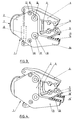
- Figure 1 représente schématiquement une vue en élévation latérale d'une pince-cisaille selon l'invention, suivant un premier mode de réalisation, la pince étant en position de fermeture maximale ;
- Figure 2 illustre le dispositif de la figure 1 en position d'ouverture maximale de la pince ;
- Figure 3 est une vue en perspective de la pince-cisaille de la figure 1 ;
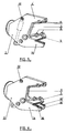
- Figure 4 est une vue en perspective d'une variante de réalisation dans laquelle la cisaille comporte deux bras fixes jumelés et un bras mobile ;
- Figure 5 est une vue en perspective d'un autre mode de réalisation dans lequel la pince et la cisaille ont un seul bras mobile qui est commun ;
- Figure 6 représente, également vue en perspective, une variante du dispositif de la figure 5 dans laquelle la cisaille comporte deux bras fixes jumelés ;
- Figure 7 illustre le profil et le montage des lames de coupe de la cisaille, et
- Figure 8 illustre l'agencement des dents de la pince brise-béton.
- Figure 1 schematically shows a side elevational view of a shear forceps according to the invention, according to a first embodiment, the forceps being in the maximum closed position;
- Figure 2 illustrates the device of Figure 1 in the maximum open position of the clamp;
- Figure 3 is a perspective view of the wire cutter of Figure 1;
- Figure 4 is a perspective view of an alternative embodiment in which the shears comprises two twin fixed arms and a movable arm;
- Figure 5 is a perspective view of another embodiment in which the pliers and the shears have a single movable arm which is common;
- Figure 6 shows, also in perspective, a variant of the device of FIG. 5 in which the shears comprise two twin fixed arms;
- Figure 7 illustrates the profile and mounting of the shear cutting blades, and
- Figure 8 illustrates the arrangement of the teeth of the concrete breaker pliers.
La pince brise-béton illustrée par les figures 1 à 3 comprend un bâti 1 formé de deux flasques 2 et 3 sur et entre lesquels sont articulés deux bras 4 et 5 brise-béton.The concrete breaker pliers illustrated in FIGS. 1 to 3 comprises a
L'ensemble 1-5 est monté rotatif infini, par moteur hydraulique et joint tournant, sur une pièce d'adaptation 6 de conception classique, destinée à être montée, à la manière connue, a l'extrémité de la flèche d'une pelle mécanique par exemple. Entre la pièce 6 et le bâti 1 est interposé le dispositif de rotation avec sa couronne à billes fixe 7 ; une régulation hydraulique supportant les efforts intempestifs sur l'ensemble de commande de rotation.The assembly 1-5 is mounted infinitely rotatable, by hydraulic motor and rotating joint, on an
Les bras 4 et 5 constituent des leviers flanqués de tourillons 8 et 9 engagés dans des paliers 10 réalisés dans les deux flasques 2 et 3.The
L'une des extrémités des bras 4 et 5, côté intérieur, porte des dents 11 montées amovibles, cependant qu'entre les autres extrémités desdits bras est agencé un vérin hydraulique à double effet 12 interposé entre les flasques 2 et 3.One of the ends of the
Le débattement angulaire des bras 4 et 5 est limité par une butée 13 solidaire du bâti 1 et une lumière arquée 14 conformée dans chaque bras et dans laquelle peut coulisser la butée 13.The angular movement of the
L'un des flasques (2) comporte, d'un côté, un prolongement en forme de bras 14 dont l'extrémité constitue l'un des bras d'une cisaille dont l'autre bras est formé par le bras 5 de la pince.One of the flanges (2) has, on one side, an extension in the form of an
Les organes actifs de la cisaille sont constitués de lames de coupe 15 et 16 montées amovibles respectivement sur les flancs en regard des bras 5 et 14 respectivement.The active members of the shears consist of
L'agencement du bras 14 est tel qu'en position de fermeture maximale de la pince (4, 5) telle qu'illustrée par les figures 1 et 3, l'ouverture de la cisaille (5, 14) est maximale, alors qu'en position d'ouverture maximale de la pince (figure 2), la cisaille est complétement fermée. Les lames 15 et 16 sont disposées aux extrémités des bras 5 et 14 afin de saisir les fers avec la plus grande ouverture possible et une plus grande facilité d'accès aux fers et de saisie de ces derniers.The arrangement of the
La figure 7 illustre la forme et le montage des lames 15 et 16. Celles-ci sont constituées, conformément à l'invention, d'une plaque allongée munie sur l'une de ses faces d'une série de dents 17 dont le profil dissymétrique est déterminé de manière à retenir les fers dans la cisaille et les empêcher de glisser au dehors lors de la fermeture des bras 5, 14. Ceci permet de sectionner efficacement les fers, à l'unité ou en groupe. A cet effet, chaque dent 17 comprend un flanc 17a sensiblement vertical, par rapport au plan général de la plaque de lame, un flanc 17b légèrement incliné en direction de l'extérieur de la cisaille et un chaufrein 17c de raccordement entre les deux flancs 17a, 17b, évitant toute arête vive et donc fragile à l'extrémité des dents.FIG. 7 illustrates the shape and mounting of the
Le montage amovible des lames 15 et 16 permet un réaffutage de l'arête de coupe par meulage de l'un des flancs latéraux des lames.The removable mounting of the
Le réglage latéral des lames 15 et 16 sur les bras 5, 14 est possible grâce à des perçages allongés 18 réalisés dans les lames et dans lesquels sont engagés des boulons de fixation.Lateral adjustment of the
Les dents 11 du brise-béton sont de préférence constituées de pièces (figure 8) comprenant un pieds d'ancrage 19 tronconique engagé dans un logement de forme correspondante ménagé dans le bras récepteur (4, 5) et retenu en place par une groupille 20. Ce montage permet de reporter sur ledit logement tronconique l'ensemble des efforts exercés sur la dent 11 dont la partie externe 21 est légèrement en retrait de la face en regard du bras porteur.The
Le caractère amovible des dents 11 et des lames 15, 16 permet de remplacer des pièces endommagées et éventuellement de substituer aux pièces actuelles des pièces de caractéristiques (forme, nature du matériau) mieux adaptées aux travaux envisagés. Actuellement celà n'est pas possible, notamment avec les dents des brise-béton connus, qui sont formées de dépôts de soudure superposées sur les bras de la pince, ces dents devant être en outre périodiquement régénérées pour cause d'usure. Il est à noter qu'avec le dispositif de l'invention lorsque la pince brise-béton (4, 5) a brisé complètement par exemple une poutre en béton armée, elle se trouve alors en position complètement fermée (figure 1), la cisaille (5, 14) étant en position d'ouverture maximale et donc immédiatement prête à saisir et sectionner des fers d'armature. Au contraire, avec les pinces connues il faut ouvrir complétement la pince puisque la cisaille se trouve au fond de celle-ci. De même, en fin de cisaillage la pince se trouve en position d'ouverture maximale donc prête à intervenir.The removable nature of the
Il faut également noter que dans la pince de l'invention le fond de la pince (entre les dents 11 et le bâti 1) est bien dégagé contrairement aux dispositifs connus ce qui facilite d'autant la saisie et le travail de la pince.It should also be noted that, in the clamp of the invention, the bottom of the clamp (between the
Les butées de fin de course (13, 13') sont nécessaires, du fait que les bras 4 et 5 sont libres en rotation, afin que dans leurs positions extrêmes, d'ouverture et de fermeture, lesdits bras 4 et 5 soient symétriques par rapport à l'axe de la pince et que la cisaille effectue convenablement son travail.The end of travel stops (13, 13 ') are necessary, since the
La figure 4 illustre une variante du dispositif de la figure 3 selon laquelle un second bras 14′, parallèle au bras 14, est prévu à l'aide d'un prolongement du flasque 3. Ce bras 14′ est muni d'une lame de coupe 16′ parallèle à la lame 16, le bras 5 de la pince se mouvant entre les deux bras fixes 14, 14′.FIG. 4 illustrates a variant of the device of FIG. 3 according to which a
Dans le mode de réalisation de la figure 5, la pince brise-béton comporte un bras 5 mobile constituant également l'un des éléments de la cisaille, exactement comme dans le mode de réalisation de la figure 3, mais ce bras 5 coopère avec un bras 4′ fixe, et non plus mobile, et constitué à partir d'un prolongement des deux flasques 2 et 3.In the embodiment of FIG. 5, the concrete breaker pliers comprises a
Le vérin 12 de commande du bras 5 est ancré en 22 sur le bâti 1.The
Enfin, la figure 6 illustre une variante du dispositif de la figure 5 dans laquelle le bras fixe 14 de la cisaille est doublé d'un second bras fixe 14′ comme dans le mode de réalisation de la figure 4, le bâti 1 présentant ainsi une forme générale de U.Finally, Figure 6 illustrates a variant of the device of Figure 5 in which the fixed
D'une manière générale l'invention n'est évidemment pas limitée aux modes de réalisation représentés et décrits ci-dessus mais en couvre au contraire toutes les variantes notamment en ce qui concerne les formes et agencements des lames 16, des dents 11 et des divers bras 4, 5, 14, 4′, 14′.In general, the invention is obviously not limited to the embodiments shown and described above, but on the contrary covers all variants thereof, in particular as regards the shapes and arrangements of the
Claims (9)
- Concrete-breaking nippers, of the type having a support (1) mounted so as to rotate, carrying both two nipper arms (4, 5), at least one of which (5) is movable with respect to the support, and shearing members (15, 16, 16'), characterised in that the said support is formed by two plates (2, 3) and in that the shearing members are mounted, on the one hand (16, 16'), on at least one fixed arm (14), formed by an extension of one (2) of the plates, and on the other hand (15), on the said movable arm (5) of the nippers, the said fixed arm (14) and movable arm (5) being side by side in the maximum opening position of the nippers, so as to give the shearing tool (5, 14) its maximum closure in this position.
- Concrete-breaking nippers according to Claim 1, characterised in that the two arms of the nippers (4, 5) are articulated on the support (1).
- Concrete-breaking nippers according to Claim 1 or 2, characterised in that the two arms of the nippers (4, 5) form levers whose ends which are opposite to the ends equipped with crushing teeth (11) are connected by a double-acting hydraulic cylinder (12), the said levers being mounted so as to rotate freely on the support (1) and equipped with stops (13, 13') limiting the angular movement of the said arms.
- Concrete-breaking nippers according to one of Claims 1 to 3, characterised in that the said fixed arm (14) is replicated by a parallel second fixed arm (14'), the said arm (5), which performs the functions of concrete breaker and shearing tool, being mounted so as to be movable between the aforesaid two arms (14, 14').
- Concrete-breaking nippers according to Claim 1, characterised in that the arm of the nippers (4') other than the one (5) performing the concrete breaker and shearing tool functions is fixed.
- Concrete-breaking nippers according to Claim 5, characterised in that the said fixed nipper arm (4') consists of an extension of the plates (2, 3) for mounting the nipper arms (4, 5).
- Concrete-breaking nippers according to Claim 5 or 6, characterised in that the fixed arm (14) forming one of the components of the shearing tool is replicated by a parallel second fixed arm (14'), the said nipper arm (5) performing the functions of concrete breaker and shearing tool being mounted so as to be movable between the aforesaid two arms (14, 14').
- Concrete-breaking nippers according to one of Claims 1 to 7, characterised in that the cutting blades (15, 16, 16') of the shearing tool are detachable and consist of plates with teeth (17) with an asymmetrical profile (17a, 17b) mounted so as to be adjustable in position on the arms (5, 14, 14').
- Concrete-breaking nippers according to one of Claims 1 to 8, characterised in that the arms (4, 4', 5) of the nippers carry teeth (11) having anchoring bases (19) held in place by pins (20) in housings of an appropriate shape bearing all the forces exerted on the said teeth (11).
Priority Applications (1)
| Application Number | Priority Date | Filing Date | Title |
|---|---|---|---|
| AT8989450013T ATE105354T1 (en) | 1988-09-30 | 1989-09-29 | SHEARS FOR CONCRETE BREAKING. |
Applications Claiming Priority (2)
| Application Number | Priority Date | Filing Date | Title |
|---|---|---|---|
| FR8812994A FR2637303B1 (en) | 1988-09-30 | 1988-09-30 | CONCRETE BREAKERS |
| FR8812994 | 1988-09-30 |
Publications (2)
| Publication Number | Publication Date |
|---|---|
| EP0362098A1 EP0362098A1 (en) | 1990-04-04 |
| EP0362098B1 true EP0362098B1 (en) | 1994-05-04 |
Family
ID=9370682
Family Applications (1)
| Application Number | Title | Priority Date | Filing Date |
|---|---|---|---|
| EP89450013A Expired - Lifetime EP0362098B1 (en) | 1988-09-30 | 1989-09-29 | Shears for crushing concrete |
Country Status (8)
| Country | Link |
|---|---|
| US (1) | US4951886A (en) |
| EP (1) | EP0362098B1 (en) |
| JP (1) | JP3061388B2 (en) |
| KR (1) | KR900005033A (en) |
| AT (1) | ATE105354T1 (en) |
| CA (1) | CA1335443C (en) |
| DE (1) | DE68915100T2 (en) |
| FR (1) | FR2637303B1 (en) |
Families Citing this family (45)
| Publication number | Priority date | Publication date | Assignee | Title |
|---|---|---|---|---|
| US5004168A (en) * | 1989-11-13 | 1991-04-02 | Brian Purser | Crushing apparatus |
| US5044569A (en) * | 1989-12-15 | 1991-09-03 | Labounty Roy E | Rock and coral demolition tool |
| DE4013126A1 (en) * | 1990-04-25 | 1991-10-31 | Helmut Wack | DEMOLITION DEVICE |
| DE4022689A1 (en) * | 1990-05-31 | 1991-12-05 | Rolf Mieger | SPOON |
| US5044568A (en) * | 1990-08-20 | 1991-09-03 | Takachiho Kogyo Yuugen Kaisha | Hand crusher with rotatably mounted handle |
| US5187868A (en) * | 1992-06-16 | 1993-02-23 | Hall Charlie R | Metal demolition shear |
| JP3063940B2 (en) * | 1992-07-07 | 2000-07-12 | 株式会社坂戸工作所 | Natural crushed stone crushing system |
| DE9210292U1 (en) * | 1992-07-31 | 1992-10-22 | Mieger, Rolf, 7951 Kirchdorf, De | |
| JPH0657970A (en) * | 1992-08-10 | 1994-03-01 | Ooyodo Diesel Kk | Concrete crusher |
| JP2585939B2 (en) * | 1993-01-26 | 1997-02-26 | 大淀小松株式会社 | Crushing equipment |
| JP2577181B2 (en) * | 1993-06-16 | 1997-01-29 | 大淀ヂ−ゼル株式会社 | Universal demolition machine |
| US5474242A (en) * | 1994-10-11 | 1995-12-12 | The Stanley Works | Demolition tools with jaws having replaceable working surfaces |
| FR2735709B1 (en) * | 1995-06-26 | 1997-08-14 | Dorguin Jean Pierre | SHEARING DEVICE, PARTICULARLY FOR CUTTING METALS OR CONCRETE |
| US5626457A (en) * | 1995-11-20 | 1997-05-06 | Action Machinery Company Of Alabama, Inc. | Grapple impactor |
| AT403491B (en) * | 1996-02-15 | 1998-02-25 | Wimmer Alois Ing | CONCRETE CRUSHERS with CUTTING SHEARS |
| JP3156754B2 (en) * | 1996-10-15 | 2001-04-16 | 大淀ヂーゼル株式会社 | Crushing equipment |
| US5894666A (en) * | 1997-03-17 | 1999-04-20 | Npk Research, Inc. | Cutting and piercing tips for a metal cutting shear |
| DE59800062D1 (en) * | 1998-04-06 | 2000-01-13 | Thyssen Henschel Gmbh | Tool for mounting on manipulators for handling and / or processing workpieces vzw. of castings |
| US6061911A (en) * | 1998-11-25 | 2000-05-16 | Genesis Equipment And Manufacturing Co. | Heavy-duty demolition apparatus with blade stabilizing device |
| US6926217B1 (en) | 1998-11-25 | 2005-08-09 | Genesis Attachments, Llc | Heavy-duty demolition apparatus with replaceable tip and rotatable cross blade |
| US6119970A (en) * | 1998-11-25 | 2000-09-19 | Genesis Equipment & Manufacturing, Inc. | Heavy-duty demolition apparatus with replaceable crushing and shearing tip |
| US7954742B2 (en) * | 1999-10-15 | 2011-06-07 | Ramun John R | Dual purpose adapter for a multiple tool attachment system |
| US8308092B2 (en) * | 1999-10-15 | 2012-11-13 | Ramun John R | Multiple tool attachment system with universal body with grapple |
| US6994284B1 (en) | 1999-10-15 | 2006-02-07 | Ramun John R | Multiple tool attachment system |
| ATE234970T1 (en) * | 1999-12-30 | 2003-04-15 | Franz Muri | CONCRETE BRUSHING PLIERS |
| GB0111519D0 (en) * | 2001-05-11 | 2001-07-04 | Purser Brian | Breaking apparatus |
| US6839969B2 (en) | 2002-11-18 | 2005-01-11 | Genesis Equipment And Manufacturing, Inc. | Replaceable demolition shear piercing tip |
| US8146256B2 (en) | 2003-10-31 | 2012-04-03 | Stanley Black & Decker, Inc. | Metal demolition shears with indexable, integrated wear plate/piercing tip |
| US7216575B2 (en) * | 2004-03-29 | 2007-05-15 | Genesis Attachments, Llc | Heavy-duty demolition apparatus with blade stabilizing puck |
| US7284718B2 (en) * | 2005-06-29 | 2007-10-23 | Genesis Attachments, Llc | Excavator demolition attachment with interchangeable jaw assemblies |
| US7264190B2 (en) * | 2005-07-05 | 2007-09-04 | Construction Equipment Company | Material breaker system |
| US20070145171A1 (en) * | 2005-12-23 | 2007-06-28 | The Stanley Works | Rebar cutting shears |
| WO2009146185A2 (en) * | 2008-04-16 | 2009-12-03 | Apopka Recycling, Inc. | A roller jaw crusher system and method |
| WO2010133862A2 (en) * | 2009-05-19 | 2010-11-25 | Michael John Williams | Pile cropping apparatus |
| US8231071B2 (en) * | 2009-08-07 | 2012-07-31 | John R. Ramun | Blade set for jaws used in rail breaking demolition equipment |
| US8628035B2 (en) * | 2009-08-07 | 2014-01-14 | John R. Ramun | Blade set for jaws used in rail breaking demolition equipment |
| JP3168361U (en) * | 2011-03-29 | 2011-06-09 | 株式会社むすび倶楽部 | Paper lasso or paper leasing |
| US8646709B2 (en) | 2012-04-11 | 2014-02-11 | John R. Ramun | Jaw set with serrated cutting blades |
| US8800902B2 (en) * | 2012-06-04 | 2014-08-12 | Seung Hwan KO | Attachment with interchangeable jaw |
| USD752114S1 (en) * | 2012-06-04 | 2016-03-22 | Caterpillar Work Tools B.V. | Multi-processor and modular wear protection system |
| ES2689488T3 (en) * | 2012-06-07 | 2018-11-14 | Caterpillar Work Tools B. V. | A set of jaws for a demolition tool |
| ES2821810T3 (en) * | 2014-05-27 | 2021-04-27 | Savonlinnan Pr Urakointi Oy | Apparatus for demolishing a concrete structure |
| USD748694S1 (en) * | 2015-03-19 | 2016-02-02 | Buckhurst Group Limited | Pipe-crushing apparatus |
| FI127105B (en) * | 2016-11-25 | 2017-11-15 | Savonlinnan Pr-Urakointi Oy | Demolition equipment and machine for dismantling the concrete structure |
| FI130556B (en) | 2017-02-28 | 2023-11-17 | Savonlinnan Pr Urakointi Oy | Double acting demolition device and utility machine for demolishing structures |
Family Cites Families (9)
| Publication number | Priority date | Publication date | Assignee | Title |
|---|---|---|---|---|
| US2044624A (en) * | 1935-09-27 | 1936-06-16 | Walter D Morgan | Combined pulling, picking-up, and transporting attachment for excavators |
| DE2722258A1 (en) * | 1977-05-17 | 1978-11-23 | Oskar Welz | Mobile scrap metal shear - forms unit detachably mounted on excavator boom and driven from hydraulic or pneumatic system |
| US4196862A (en) * | 1978-09-06 | 1980-04-08 | Ituo Tagawa | Apparatus for crushing building materials |
| GB2071053A (en) * | 1980-03-10 | 1981-09-16 | Labounty Roy E | Improved grapple and shear assembly |
| JPS6062373A (en) * | 1983-09-16 | 1985-04-10 | 重水 昭彦 | Concrete crusher |
| US4776524A (en) * | 1985-12-04 | 1988-10-11 | Sakato Kousakusho Kabushiki Kaisha | Crusher |
| US4719975A (en) * | 1986-02-28 | 1988-01-19 | Labounty Kenneth R | Rotating hammer-shear |
| DE8704655U1 (en) * | 1987-04-01 | 1987-06-25 | Wack, Helmut, 6653 Blieskastel, De | |
| US4838493B1 (en) * | 1988-06-10 | 1994-12-06 | Labounty Manufacturing | Concrete crusher |
-
1988
- 1988-09-30 FR FR8812994A patent/FR2637303B1/en not_active Expired - Fee Related
-
1989
- 1989-09-27 CA CA000613584A patent/CA1335443C/en not_active Expired - Fee Related
- 1989-09-29 EP EP89450013A patent/EP0362098B1/en not_active Expired - Lifetime
- 1989-09-29 US US07/414,249 patent/US4951886A/en not_active Expired - Fee Related
- 1989-09-29 KR KR1019890014164A patent/KR900005033A/en active IP Right Grant
- 1989-09-29 AT AT8989450013T patent/ATE105354T1/en not_active IP Right Cessation
- 1989-09-29 DE DE68915100T patent/DE68915100T2/en not_active Expired - Lifetime
- 1989-09-30 JP JP1256923A patent/JP3061388B2/en not_active Expired - Lifetime
Also Published As
| Publication number | Publication date |
|---|---|
| JPH02120461A (en) | 1990-05-08 |
| FR2637303A1 (en) | 1990-04-06 |
| CA1335443C (en) | 1995-05-02 |
| FR2637303B1 (en) | 1990-12-14 |
| DE68915100T2 (en) | 1994-11-17 |
| KR900005033A (en) | 1990-04-13 |
| EP0362098A1 (en) | 1990-04-04 |
| DE68915100D1 (en) | 1994-06-09 |
| JP3061388B2 (en) | 2000-07-10 |
| ATE105354T1 (en) | 1994-05-15 |
| US4951886A (en) | 1990-08-28 |
Similar Documents
| Publication | Publication Date | Title |
|---|---|---|
| EP0362098B1 (en) | Shears for crushing concrete | |
| FR2532868A1 (en) | ||
| EP0751260B1 (en) | Shearing device, specially for cutting metals or concrete | |
| FR2549753A1 (en) | HANDLING AND SHEARING ACCESSORY FOR BACKHOE SHOVEL | |
| FR2634680A1 (en) | ROTATION ADJUSTMENT APPARATUS FOR DEMOLITION SHEARS | |
| EP0135490B1 (en) | Extractor with grips | |
| EP0273788B1 (en) | Machine for felling and trimming trees | |
| FR2776307A1 (en) | DRAWING MECHANISM FOR ARMOR AND WEAVING MECHANISM COMPRISING SUCH A DRAWING MECHANISM | |
| EP0435796A1 (en) | Bucket provided with adjustable width for earth moving machines | |
| EP0374334B1 (en) | Hydraulic cutting device | |
| EP0262048B1 (en) | Device for automatically lapping the electrodes of welding robots | |
| EP1576871B1 (en) | Gripping device for uprooting bushes | |
| FR2746050A1 (en) | DEVICE FOR LONGITUDINAL CUTTING OF A TUBE | |
| FR2924305A1 (en) | Stump-extracting tool for extracting and cutting tree stumps, has jaw including blades independently mounted with respect to each other, where blades have units for driving blades for synchronous or asynchronous displacement of blades | |
| FR2708491A1 (en) | Device for preassembling two pieces to be crimped together | |
| FR2898826A1 (en) | SUPPORTING AND GUIDING DEVICE FOR A RAIL CHAINSAW OR THE LIKE | |
| EP0011545B1 (en) | Interchangeable knife for a bolt cutter | |
| FR2643663A1 (en) | INTERCHANGEABLE SHEAR BUCKET | |
| EP0169759B1 (en) | Loading apparatus for silo unloaders-distributors | |
| EP1904245A1 (en) | Crimping head | |
| EP3047722B1 (en) | Improved cutting tool with anvil | |
| EP0496683A1 (en) | Pruning apparatus | |
| FR2715095A1 (en) | Metal cutter with hydraulic control | |
| BE493112A (en) | ||
| FR2626441A1 (en) | Machine for peeling and cutting leeks |
Legal Events
| Date | Code | Title | Description |
|---|---|---|---|
| PUAI | Public reference made under article 153(3) epc to a published international application that has entered the european phase |
Free format text: ORIGINAL CODE: 0009012 |
|
| AK | Designated contracting states |
Kind code of ref document: A1 Designated state(s): AT BE CH DE ES GB GR IT LI LU NL SE |
|
| 17P | Request for examination filed |
Effective date: 19900917 |
|
| 17Q | First examination report despatched |
Effective date: 19911016 |
|
| GRAA | (expected) grant |
Free format text: ORIGINAL CODE: 0009210 |
|
| AK | Designated contracting states |
Kind code of ref document: B1 Designated state(s): AT BE CH DE ES GB GR IT LI LU NL SE |
|
| PG25 | Lapsed in a contracting state [announced via postgrant information from national office to epo] |
Ref country code: IT Free format text: LAPSE BECAUSE OF FAILURE TO SUBMIT A TRANSLATION OF THE DESCRIPTION OR TO PAY THE FEE WITHIN THE PRESCRIBED TIME-LIMIT;WARNING: LAPSES OF ITALIAN PATENTS WITH EFFECTIVE DATE BEFORE 2007 MAY HAVE OCCURRED AT ANY TIME BEFORE 2007. THE CORRECT EFFECTIVE DATE MAY BE DIFFERENT FROM THE ONE RECORDED. Effective date: 19940504 Ref country code: GR Free format text: LAPSE BECAUSE OF FAILURE TO SUBMIT A TRANSLATION OF THE DESCRIPTION OR TO PAY THE FEE WITHIN THE PRESCRIBED TIME-LIMIT Effective date: 19940504 Ref country code: ES Free format text: THE PATENT HAS BEEN ANNULLED BY A DECISION OF A NATIONAL AUTHORITY Effective date: 19940504 Ref country code: SE Free format text: THE PATENT HAS BEEN ANNULLED BY A DECISION OF A NATIONAL AUTHORITY Effective date: 19940504 |
|
| REF | Corresponds to: |
Ref document number: 105354 Country of ref document: AT Date of ref document: 19940515 Kind code of ref document: T |
|
| REF | Corresponds to: |
Ref document number: 68915100 Country of ref document: DE Date of ref document: 19940609 |
|
| GBT | Gb: translation of ep patent filed (gb section 77(6)(a)/1977) |
Effective date: 19940523 |
|
| PG25 | Lapsed in a contracting state [announced via postgrant information from national office to epo] |
Ref country code: LU Free format text: LAPSE BECAUSE OF NON-PAYMENT OF DUE FEES Effective date: 19940930 |
|
| PLBE | No opposition filed within time limit |
Free format text: ORIGINAL CODE: 0009261 |
|
| STAA | Information on the status of an ep patent application or granted ep patent |
Free format text: STATUS: NO OPPOSITION FILED WITHIN TIME LIMIT |
|
| 26N | No opposition filed | ||
| PGFP | Annual fee paid to national office [announced via postgrant information from national office to epo] |
Ref country code: CH Payment date: 20000925 Year of fee payment: 12 |
|
| PGFP | Annual fee paid to national office [announced via postgrant information from national office to epo] |
Ref country code: AT Payment date: 20000926 Year of fee payment: 12 Ref country code: GB Payment date: 20000926 Year of fee payment: 12 |
|
| PGFP | Annual fee paid to national office [announced via postgrant information from national office to epo] |
Ref country code: NL Payment date: 20000930 Year of fee payment: 12 |
|
| PGFP | Annual fee paid to national office [announced via postgrant information from national office to epo] |
Ref country code: BE Payment date: 20001103 Year of fee payment: 12 |
|
| PGFP | Annual fee paid to national office [announced via postgrant information from national office to epo] |
Ref country code: DE Payment date: 20001122 Year of fee payment: 12 |
|
| PG25 | Lapsed in a contracting state [announced via postgrant information from national office to epo] |
Ref country code: GB Free format text: LAPSE BECAUSE OF NON-PAYMENT OF DUE FEES Effective date: 20010929 Ref country code: AT Free format text: LAPSE BECAUSE OF NON-PAYMENT OF DUE FEES Effective date: 20010929 |
|
| PG25 | Lapsed in a contracting state [announced via postgrant information from national office to epo] |
Ref country code: LI Free format text: LAPSE BECAUSE OF NON-PAYMENT OF DUE FEES Effective date: 20010930 Ref country code: CH Free format text: LAPSE BECAUSE OF NON-PAYMENT OF DUE FEES Effective date: 20010930 Ref country code: BE Free format text: LAPSE BECAUSE OF NON-PAYMENT OF DUE FEES Effective date: 20010930 |
|
| REG | Reference to a national code |
Ref country code: GB Ref legal event code: IF02 |
|
| BERE | Be: lapsed |
Owner name: AMECA Effective date: 20010930 |
|
| PG25 | Lapsed in a contracting state [announced via postgrant information from national office to epo] |
Ref country code: NL Free format text: LAPSE BECAUSE OF NON-PAYMENT OF DUE FEES Effective date: 20020401 |
|
| PG25 | Lapsed in a contracting state [announced via postgrant information from national office to epo] |
Ref country code: DE Free format text: LAPSE BECAUSE OF NON-PAYMENT OF DUE FEES Effective date: 20020501 |
|
| REG | Reference to a national code |
Ref country code: CH Ref legal event code: PL |
|
| GBPC | Gb: european patent ceased through non-payment of renewal fee |
Effective date: 20010929 |
|
| NLV4 | Nl: lapsed or anulled due to non-payment of the annual fee |
Effective date: 20020401 |
|
| NLV4 | Nl: lapsed or anulled due to non-payment of the annual fee |
Effective date: 20020401 |