EP0365286A2 - A small-sized electronic apparatus - Google Patents
A small-sized electronic apparatus Download PDFInfo
- Publication number
- EP0365286A2 EP0365286A2 EP89310663A EP89310663A EP0365286A2 EP 0365286 A2 EP0365286 A2 EP 0365286A2 EP 89310663 A EP89310663 A EP 89310663A EP 89310663 A EP89310663 A EP 89310663A EP 0365286 A2 EP0365286 A2 EP 0365286A2
- Authority
- EP
- European Patent Office
- Prior art keywords
- cover
- battery
- battery compartment
- electronic apparatus
- small
- Prior art date
- Legal status (The legal status is an assumption and is not a legal conclusion. Google has not performed a legal analysis and makes no representation as to the accuracy of the status listed.)
- Granted
Links
Images
Classifications
-
- G—PHYSICS
- G06—COMPUTING; CALCULATING OR COUNTING
- G06F—ELECTRIC DIGITAL DATA PROCESSING
- G06F1/00—Details not covered by groups G06F3/00 - G06F13/00 and G06F21/00
- G06F1/16—Constructional details or arrangements
- G06F1/1613—Constructional details or arrangements for portable computers
- G06F1/1626—Constructional details or arrangements for portable computers with a single-body enclosure integrating a flat display, e.g. Personal Digital Assistants [PDAs]
-
- G—PHYSICS
- G06—COMPUTING; CALCULATING OR COUNTING
- G06F—ELECTRIC DIGITAL DATA PROCESSING
- G06F1/00—Details not covered by groups G06F3/00 - G06F13/00 and G06F21/00
- G06F1/16—Constructional details or arrangements
- G06F1/1613—Constructional details or arrangements for portable computers
- G06F1/1633—Constructional details or arrangements of portable computers not specific to the type of enclosures covered by groups G06F1/1615 - G06F1/1626
- G06F1/1635—Details related to the integration of battery packs and other power supplies such as fuel cells or integrated AC adapter
-
- G—PHYSICS
- G06—COMPUTING; CALCULATING OR COUNTING
- G06F—ELECTRIC DIGITAL DATA PROCESSING
- G06F1/00—Details not covered by groups G06F3/00 - G06F13/00 and G06F21/00
- G06F1/26—Power supply means, e.g. regulation thereof
- G06F1/263—Arrangements for using multiple switchable power supplies, e.g. battery and AC
-
- G—PHYSICS
- G06—COMPUTING; CALCULATING OR COUNTING
- G06F—ELECTRIC DIGITAL DATA PROCESSING
- G06F11/00—Error detection; Error correction; Monitoring
- G06F11/004—Error avoidance
-
- G—PHYSICS
- G06—COMPUTING; CALCULATING OR COUNTING
- G06K—GRAPHICAL DATA READING; PRESENTATION OF DATA; RECORD CARRIERS; HANDLING RECORD CARRIERS
- G06K19/00—Record carriers for use with machines and with at least a part designed to carry digital markings
- G06K19/06—Record carriers for use with machines and with at least a part designed to carry digital markings characterised by the kind of the digital marking, e.g. shape, nature, code
- G06K19/067—Record carriers with conductive marks, printed circuits or semiconductor circuit elements, e.g. credit or identity cards also with resonating or responding marks without active components
- G06K19/07—Record carriers with conductive marks, printed circuits or semiconductor circuit elements, e.g. credit or identity cards also with resonating or responding marks without active components with integrated circuit chips
- G06K19/0701—Record carriers with conductive marks, printed circuits or semiconductor circuit elements, e.g. credit or identity cards also with resonating or responding marks without active components with integrated circuit chips at least one of the integrated circuit chips comprising an arrangement for power management
- G06K19/0702—Record carriers with conductive marks, printed circuits or semiconductor circuit elements, e.g. credit or identity cards also with resonating or responding marks without active components with integrated circuit chips at least one of the integrated circuit chips comprising an arrangement for power management the arrangement including a battery
- G06K19/0706—Record carriers with conductive marks, printed circuits or semiconductor circuit elements, e.g. credit or identity cards also with resonating or responding marks without active components with integrated circuit chips at least one of the integrated circuit chips comprising an arrangement for power management the arrangement including a battery the battery being replaceable
-
- G—PHYSICS
- G06—COMPUTING; CALCULATING OR COUNTING
- G06K—GRAPHICAL DATA READING; PRESENTATION OF DATA; RECORD CARRIERS; HANDLING RECORD CARRIERS
- G06K19/00—Record carriers for use with machines and with at least a part designed to carry digital markings
- G06K19/06—Record carriers for use with machines and with at least a part designed to carry digital markings characterised by the kind of the digital marking, e.g. shape, nature, code
- G06K19/067—Record carriers with conductive marks, printed circuits or semiconductor circuit elements, e.g. credit or identity cards also with resonating or responding marks without active components
- G06K19/07—Record carriers with conductive marks, printed circuits or semiconductor circuit elements, e.g. credit or identity cards also with resonating or responding marks without active components with integrated circuit chips
- G06K19/077—Constructional details, e.g. mounting of circuits in the carrier
-
- G—PHYSICS
- G11—INFORMATION STORAGE
- G11C—STATIC STORES
- G11C5/00—Details of stores covered by group G11C11/00
- G11C5/14—Power supply arrangements, e.g. power down, chip selection or deselection, layout of wirings or power grids, or multiple supply levels
- G11C5/141—Battery and back-up supplies
-
- H—ELECTRICITY
- H01—ELECTRIC ELEMENTS
- H01M—PROCESSES OR MEANS, e.g. BATTERIES, FOR THE DIRECT CONVERSION OF CHEMICAL ENERGY INTO ELECTRICAL ENERGY
- H01M50/00—Constructional details or processes of manufacture of the non-active parts of electrochemical cells other than fuel cells, e.g. hybrid cells
- H01M50/20—Mountings; Secondary casings or frames; Racks, modules or packs; Suspension devices; Shock absorbers; Transport or carrying devices; Holders
- H01M50/204—Racks, modules or packs for multiple batteries or multiple cells
-
- H—ELECTRICITY
- H01—ELECTRIC ELEMENTS
- H01M—PROCESSES OR MEANS, e.g. BATTERIES, FOR THE DIRECT CONVERSION OF CHEMICAL ENERGY INTO ELECTRICAL ENERGY
- H01M50/00—Constructional details or processes of manufacture of the non-active parts of electrochemical cells other than fuel cells, e.g. hybrid cells
- H01M50/20—Mountings; Secondary casings or frames; Racks, modules or packs; Suspension devices; Shock absorbers; Transport or carrying devices; Holders
- H01M50/247—Mountings; Secondary casings or frames; Racks, modules or packs; Suspension devices; Shock absorbers; Transport or carrying devices; Holders specially adapted for portable devices, e.g. mobile phones, computers, hand tools or pacemakers
-
- H—ELECTRICITY
- H02—GENERATION; CONVERSION OR DISTRIBUTION OF ELECTRIC POWER
- H02J—CIRCUIT ARRANGEMENTS OR SYSTEMS FOR SUPPLYING OR DISTRIBUTING ELECTRIC POWER; SYSTEMS FOR STORING ELECTRIC ENERGY
- H02J7/00—Circuit arrangements for charging or depolarising batteries or for supplying loads from batteries
- H02J7/0042—Circuit arrangements for charging or depolarising batteries or for supplying loads from batteries characterised by the mechanical construction
- H02J7/0045—Circuit arrangements for charging or depolarising batteries or for supplying loads from batteries characterised by the mechanical construction concerning the insertion or the connection of the batteries
-
- H—ELECTRICITY
- H05—ELECTRIC TECHNIQUES NOT OTHERWISE PROVIDED FOR
- H05K—PRINTED CIRCUITS; CASINGS OR CONSTRUCTIONAL DETAILS OF ELECTRIC APPARATUS; MANUFACTURE OF ASSEMBLAGES OF ELECTRICAL COMPONENTS
- H05K5/00—Casings, cabinets or drawers for electric apparatus
- H05K5/0086—Casings, cabinets or drawers for electric apparatus portable, e.g. battery operated apparatus
-
- Y—GENERAL TAGGING OF NEW TECHNOLOGICAL DEVELOPMENTS; GENERAL TAGGING OF CROSS-SECTIONAL TECHNOLOGIES SPANNING OVER SEVERAL SECTIONS OF THE IPC; TECHNICAL SUBJECTS COVERED BY FORMER USPC CROSS-REFERENCE ART COLLECTIONS [XRACs] AND DIGESTS
- Y02—TECHNOLOGIES OR APPLICATIONS FOR MITIGATION OR ADAPTATION AGAINST CLIMATE CHANGE
- Y02E—REDUCTION OF GREENHOUSE GAS [GHG] EMISSIONS, RELATED TO ENERGY GENERATION, TRANSMISSION OR DISTRIBUTION
- Y02E60/00—Enabling technologies; Technologies with a potential or indirect contribution to GHG emissions mitigation
- Y02E60/10—Energy storage using batteries
Definitions
- the present invention relates to a small-sized electronic apparatus such as an electronic organizer used for storing data, and more particularly, to a small-sized electronic apparatus having one or more replaceable batteries housed in the body of the electronic apparatus.
- a small-sized electronic apparatus such as an electronic organizer used for storing data is usually operated by one or more replaceable batteries.
- the battery or batteries are removed from the body of the apparatus with the power switch left on and hence in a data-write enabled state, the data previously stored in the apparatus may be lost or distorted. It is therefore required to turn off the power switch before removing the battery or batteries to protect the stored data.
- cautions are only given in instruction manuals or the like, instructing the user to turn off the power switch before removing the battery or batteries.
- the user may forget to turn off the power switch when replacing the battery or batteries and may remove the battery or batteries from the body of the apparatus with the power switch left on and hence in a data-write enabled state, thereby causing the stored data to be lost or distorted.
- the small-sized electronic apparatus of this invention which overcomes the above-discussed and numerous other disadvantages and deficiencies of the prior art, has one or more replaceable batteries housed in a battery compartment of the body of the apparatus, and comprises a cover which is moved to open or close said battery compartment, a switching member for switching on and off the power source, and a linking member to which said switching member is attached and which is moved with the movement of said cover to allow said switching member to turn off the power source when said cover is moved to open said battery compartment.
- the cover is slidable with respect to said body.
- the linking member is slidable in the same direction as the sliding direction of said cover, said linking member sliding together with said cover when said cover is slid in such a direction as to open said battery compartment.
- the cover is swingable with respect to said body.
- the linking member when the cover is swung in such a direction as to open said battery compartment, the linking member is pressed by said cover so as to slide.
- the invention described herein makes possible the objective of providing a small-sized electronic apparatus in which the power is automatically turned off when the cover for the battery compartment is opened, so that there is no possibility of the stored data being lost or distorted even if the user tries to replace the battery without turning off the power switch.
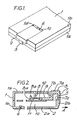
- Fig. 1 is a perspective view showing the rear side of a small-sized electronic apparatus of the invention used for storing data.
- the small-sized electronic apparatus has a body 1 housing electronic components and the like.
- the body 1 includes an upper cabinet 1a and a lower cabinet 1b , the cabinets being engaged with each other.
- a battery compartment 1c for holding a replaceable battery is provided within the lower cabinet 1b of the body 1 .
- the battery compartment 1c has an opening formed at the bottom of the lower cabinet 1b and an opening formed in the central portion of one side of the lower cabinet 1b , the two openings being formed continuously.
- the openings of the battery compartment 1c is closed or opened with a cover 2 .
- the cover 2 consists of a bottom part 2a which covers the opening formed at the bottom of the lower cabinet 1b , and an end part 2b which is formed continuously with and perpendicular to one end of the bottom part 2a to cover the opening formed on the side of the lower cabinet 1b .
- the battery compartment 1c includes side walls extending perpendicularly from the opening formed on the side of the lower cabinet 1b .
- the bottom part 2a of the cover 2 engages a slide groove 1d provided on each of the side walls for sliding thereon as shown in Fig. 1.
- the bottom part 2a of the cover 2 is provided with an engaging pawl 6 at one end thereof, the end being opposite to the one having the end part 2b .
- the engaging pawl 6 which is provided with flexibility, engages a recessed portion 1e formed on the inner surface of the battery compartment 1c of the lower cabinet 1b , thereby fixing the cover 2 to the lower cabinet 1b .
- the engaging pawl 6 is disengaged from the recessed portion 1e , the cover 2 becomes slidable to open the battery compartment 1c .
- Formed on the endmost portion of the end part 2b of the cover 2 is an upwardly extending projection 5 .
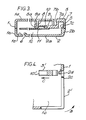
- the battery compartment 1c formed in the lower cabinet 1b is separated from the inside of the upper cabinet 1a by a circuit board 11 .
- the circuit board 11 has a circuit pattern formed on the side thereof facing the inner surface of the upper cabinet 1a .
- a linking member 3 is disposed in such a way as to slide along the circuit pattern of the circuit board 11 .
- the linking member 3 comprises a slide section 9 formed parallel to the circuit pattern of the circuit board 11 , and a link section 7 formed in continuous relationship with one end of the slide section 9 .
- the link section 7 extends outwardly from the upper cabinet 1a in such a way as to face the end part 2b of the cover 2 which covers the battery compartment 1c .
- the link section 7 consists of a side portion 7b extending upwardly from the end of the slide section 9 , an upper surface 7a formed in continuous relationship with the upper end of the side portion 7b and approximately flush with the upper surface of the upper cabinet 1a , and an outer portion 7c extending downwardly from the other end of the upper surface 7a .
- the upper surface 7a of the link section 7 is formed in a corrugated shape. In this way, the link section 7 has a U-shaped cross section with an opening facing the lower cabinet 1b .
- the lower end of the outer portion 7c is positioned to abut against the upper end face of the end part 2b of the cover 2 placed in position to close the battery compartment 1c , the lower end of the outer portion 7c thus engaging the projection 5 of the cover 2 .
- the linking member 3 is also slid in the same direction together with the cover 2 .
- the slide section 9 of the linking member 3 is provided with an upwardly protruding stopper 9a on the end thereof positioned inside the upper cabinet 1a .
- the stopper 9a abuts against a rib 8 protruding from the inner surface of the upper cabinet 1a to stop the sliding movement of the entire linking member 3 as shown in Fig. 3.
- the slide section 9 includes a recessed section 3a formed therein facing a designated portion of the circuit pattern of the circuit board 11 .
- a switching member 10 is disposed inside the recessed section 3a .
- the switching member 10 is in contact with a designated power supply pattern in the circuit pattern of the circuit board 11 to turn on the power source of the circuit pattern.
- the linking member 3 is slid together with the cover 2 until the stopper 9a abuts against the rib 8 to stop the sliding movement as shown in Fig. 3, the switching member 10 is removed from contact with the power supply pattern and so turns off the power source of the circuit pattern.
- the linking member 3 is slid in the direction of arrow A until the stopper 9a abuts against the rib 8 .
- the cover 2 is then removed from the lower cabinet 1b so that the battery in the battery compartment 1c can be replaced with a new one.
- the projection 5 formed on the end part 2b of the cover 2 is placed back into the opening of the linking member 3 , and the linking member 3 is slid in the opposite direction to allow the cover 2 to slide back until the engaging pawl 6 of the cover 2 engages the recessed portion 1e of the lower cabinet 1b , the battery compartment 1c thus being closed with the cover 2 fixed to the lower cabinet 1b .
- the linking member 3 is slid by the user pressing the corrugated upper surface 7a .
- the projection 5 formed on the upper end face of the end part 2b of the cover 2 engages the lower end of the outer portion 7c of the link section 7 of the linking member 3 .
- the switching member 10 disposed on the end of the slide section 9 of the linking member 3 is in contact with the power supply pattern on the circuit board 11 to close the power circuit.
- the inner end portion of the bottom part 2a of the cover 2 is pressed toward the inside of the lower cabinet 1b to disengage the engaging pawl 6 of the cover 2 from the recessed portion 1e of the lower cabinet 1b .
- the cover 2 is then slid in the direction of arrow A shown in Fig. 2 to open the battery compartment 1c .
- the linking member 3 is also slid together with the cover 2 in the same direction.
- the cover 2 is slid out until the stopper 9a formed on the end of the slide section 9 of the linking member 3 stops to abut against the rib 8 as shown in Fig. 3, the cover 2 being then removed from the lower cabinet 1b to open the battery compartment 1c .
- the stopper 9a of the slide section 9 of the linking member 3 stops to engage the rib 8
- the switching member 10 provided at the end of the slide section 9 is removed from contact with the power supply pattern on the circuit board 11 and so turns off the power source of the circuit board 11 . In this state, the battery housed in the battery compartment 1c is replaced with a new one.
- the power is automatically turned off when the cover 2 of the battery compartment 1c is slid for replacement of the battery.
- the power is automatically turned off when the cover 2 of the battery compartment 1c is slid for replacement of the battery.
- Fig. 4 shows another small-sized electronic apparatus of the present invention, in which a cover 2′ for opening and closing the battery compartment 1c is mounted to the body 1 in such a way that it can swing about a fulcrum 2c .
- a cover 2′ for opening and closing the battery compartment 1c is mounted to the body 1 in such a way that it can swing about a fulcrum 2c .
- a pressing member 2d attached to the cover 2′ is pressed against a linking member 3′ , the linking member 3′ then being slid in the direction of arrow C .
- a switching member 10′ is provided at the end of the linking member 3′ .
- the switching member 10′ comes out of contact with the power supply pattern on the circuit board to turn off the power when the linking member 3′ is slid in the direction of arrow C .
- the power is automatically turned off when the cover 2′ is swung to open the battery compartment 1c , so that there is no possibility of the stored data being lost or distorted.
Abstract
Description
- The present invention relates to a small-sized electronic apparatus such as an electronic organizer used for storing data, and more particularly, to a small-sized electronic apparatus having one or more replaceable batteries housed in the body of the electronic apparatus.
- A small-sized electronic apparatus such as an electronic organizer used for storing data is usually operated by one or more replaceable batteries. In such an electronic apparatus, if the battery or batteries are removed from the body of the apparatus with the power switch left on and hence in a data-write enabled state, the data previously stored in the apparatus may be lost or distorted. It is therefore required to turn off the power switch before removing the battery or batteries to protect the stored data. However, in the case of a conventional electronic apparatus, cautions are only given in instruction manuals or the like, instructing the user to turn off the power switch before removing the battery or batteries. In such a circumstance, the user may forget to turn off the power switch when replacing the battery or batteries and may remove the battery or batteries from the body of the apparatus with the power switch left on and hence in a data-write enabled state, thereby causing the stored data to be lost or distorted.
- The small-sized electronic apparatus of this invention, which overcomes the above-discussed and numerous other disadvantages and deficiencies of the prior art, has one or more replaceable batteries housed in a battery compartment of the body of the apparatus, and comprises a cover which is moved to open or close said battery compartment, a switching member for switching on and off the power source, and a linking member to which said switching member is attached and which is moved with the movement of said cover to allow said switching member to turn off the power source when said cover is moved to open said battery compartment.
- In a preferred embodiment, the cover is slidable with respect to said body.
- In a preferred embodiment, the linking member is slidable in the same direction as the sliding direction of said cover, said linking member sliding together with said cover when said cover is slid in such a direction as to open said battery compartment.
- In a preferred embodiment, the cover is swingable with respect to said body.
- In a preferred embodiment, when the cover is swung in such a direction as to open said battery compartment, the linking member is pressed by said cover so as to slide.
- Thus, the invention described herein makes possible the objective of providing a small-sized electronic apparatus in which the power is automatically turned off when the cover for the battery compartment is opened, so that there is no possibility of the stored data being lost or distorted even if the user tries to replace the battery without turning off the power switch.
- This invention may be better understood and its numerous objects and advantages will become apparent to those skilled in the art by reference to the accompanying drawings as follows:
- Fig. 1 is a perspective view showing the rear side of a small-sized electronic apparatus of the present invention.
- Fig. 2 is a cross-sectional view of the small-sized electronic apparatus of the invention.
- Fig. 3 is a cross-sectional view of the small-sized electronic apparatus at the time when a cover is slid to open a battery compartment.
- Fig. 4 is a cross-sectional view of another small-sized electronic apparatus of the present invention, illustrating the vicinity of a battery compartment.
- Fig. 1 is a perspective view showing the rear side of a small-sized electronic apparatus of the invention used for storing data. The small-sized electronic apparatus has a
body 1 housing electronic components and the like. Thebody 1 includes an upper cabinet 1a and a lower cabinet 1b, the cabinets being engaged with each other. As shown in Fig. 2, abattery compartment 1c for holding a replaceable battery is provided within the lower cabinet 1b of thebody 1. Thebattery compartment 1c has an opening formed at the bottom of the lower cabinet 1b and an opening formed in the central portion of one side of the lower cabinet 1b, the two openings being formed continuously. - The openings of the
battery compartment 1c is closed or opened with acover 2. Thecover 2 consists of abottom part 2a which covers the opening formed at the bottom of the lower cabinet 1b, and anend part 2b which is formed continuously with and perpendicular to one end of thebottom part 2a to cover the opening formed on the side of the lower cabinet 1b. Thebattery compartment 1c includes side walls extending perpendicularly from the opening formed on the side of the lower cabinet 1b. Thebottom part 2a of thecover 2 engages aslide groove 1d provided on each of the side walls for sliding thereon as shown in Fig. 1. - The
bottom part 2a of thecover 2 is provided with anengaging pawl 6 at one end thereof, the end being opposite to the one having theend part 2b. When thecover 2 is placed in position to close thebattery compartment 1c, theengaging pawl 6, which is provided with flexibility, engages a recessed portion 1e formed on the inner surface of thebattery compartment 1c of the lower cabinet 1b, thereby fixing thecover 2 to the lower cabinet 1b. When theengaging pawl 6 is disengaged from the recessed portion 1e, thecover 2 becomes slidable to open thebattery compartment 1c. Formed on the endmost portion of theend part 2b of thecover 2 is an upwardly extendingprojection 5. - The
battery compartment 1c formed in the lower cabinet 1b is separated from the inside of the upper cabinet 1a by acircuit board 11. Thecircuit board 11 has a circuit pattern formed on the side thereof facing the inner surface of the upper cabinet 1a. A linkingmember 3 is disposed in such a way as to slide along the circuit pattern of thecircuit board 11. The linkingmember 3 comprises a slide section 9 formed parallel to the circuit pattern of thecircuit board 11, and a link section 7 formed in continuous relationship with one end of the slide section 9. The link section 7 extends outwardly from the upper cabinet 1a in such a way as to face theend part 2b of thecover 2 which covers thebattery compartment 1c. The link section 7 consists of aside portion 7b extending upwardly from the end of the slide section 9, an upper surface 7a formed in continuous relationship with the upper end of theside portion 7b and approximately flush with the upper surface of the upper cabinet 1a, and an outer portion 7c extending downwardly from the other end of the upper surface 7a. The upper surface 7a of the link section 7 is formed in a corrugated shape. In this way, the link section 7 has a U-shaped cross section with an opening facing the lower cabinet 1b. The lower end of the outer portion 7c is positioned to abut against the upper end face of theend part 2b of thecover 2 placed in position to close thebattery compartment 1c, the lower end of the outer portion 7c thus engaging theprojection 5 of thecover 2. In this construction, when thecover 2 is slid to open thebattery compartment 1c, the linkingmember 3 is also slid in the same direction together with thecover 2. - The slide section 9 of the linking
member 3 is provided with an upwardly protrudingstopper 9a on the end thereof positioned inside the upper cabinet 1a. When the linkingmember 3 is slid a given distance together with thecover 2 which is slid to open thebattery compartment 1c, thestopper 9a abuts against a rib 8 protruding from the inner surface of the upper cabinet 1a to stop the sliding movement of the entire linkingmember 3 as shown in Fig. 3. Also, the slide section 9 includes arecessed section 3a formed therein facing a designated portion of the circuit pattern of thecircuit board 11. A switchingmember 10 is disposed inside therecessed section 3a. When the linkingmember 3 engages thecover 2 placed in position to close thebattery compartment 1c as shown in Fig. 2, theswitching member 10 is in contact with a designated power supply pattern in the circuit pattern of thecircuit board 11 to turn on the power source of the circuit pattern. On the other hand, when the linkingmember 3 is slid together with thecover 2 until thestopper 9a abuts against the rib 8 to stop the sliding movement as shown in Fig. 3, theswitching member 10 is removed from contact with the power supply pattern and so turns off the power source of the circuit pattern. - For the replacement of the battery, the linking
member 3 is slid in the direction of arrow A until thestopper 9a abuts against the rib 8. Thecover 2 is then removed from the lower cabinet 1b so that the battery in thebattery compartment 1c can be replaced with a new one. After completion of the replacement, theprojection 5 formed on theend part 2b of thecover 2 is placed back into the opening of the linkingmember 3, and the linkingmember 3 is slid in the opposite direction to allow thecover 2 to slide back until theengaging pawl 6 of thecover 2 engages the recessed portion 1e of the lower cabinet 1b, thebattery compartment 1c thus being closed with thecover 2 fixed to the lower cabinet 1b. The linkingmember 3 is slid by the user pressing the corrugated upper surface 7a. - In the small-sized electronic apparatus constructed as described above, when the
cover 2 is placed in position to close thebattery compartment 1c with a battery housed therein, theprojection 5 formed on the upper end face of theend part 2b of thecover 2 engages the lower end of the outer portion 7c of the link section 7 of the linkingmember 3. In this state, theswitching member 10 disposed on the end of the slide section 9 of the linkingmember 3 is in contact with the power supply pattern on thecircuit board 11 to close the power circuit. - To replace the battery housed in the
battery compartment 1c, the inner end portion of thebottom part 2a of thecover 2 is pressed toward the inside of the lower cabinet 1b to disengage theengaging pawl 6 of thecover 2 from the recessed portion 1e of the lower cabinet 1b. Thecover 2 is then slid in the direction of arrow A shown in Fig. 2 to open thebattery compartment 1c. At this time, since theprojection 5 of theend part 2b of thecover 2 engages the link section 7 of the linkingmember 3, the linkingmember 3 is also slid together with thecover 2 in the same direction. Thecover 2 is slid out until thestopper 9a formed on the end of the slide section 9 of the linkingmember 3 stops to abut against the rib 8 as shown in Fig. 3, thecover 2 being then removed from the lower cabinet 1b to open thebattery compartment 1c. When thestopper 9a of the slide section 9 of the linkingmember 3 stops to engage the rib 8, theswitching member 10 provided at the end of the slide section 9 is removed from contact with the power supply pattern on thecircuit board 11 and so turns off the power source of thecircuit board 11. In this state, the battery housed in thebattery compartment 1c is replaced with a new one. - Thus, in the small-sized electronic apparatus of the present invention, even if the user tries to replace the battery without turning off the power switch, the power is automatically turned off when the
cover 2 of thebattery compartment 1c is slid for replacement of the battery. Thus, there is no possibility of the stored data being lost or distorted at the time of the replacement of the battery. - Fig. 4 shows another small-sized electronic apparatus of the present invention, in which a
cover 2′ for opening and closing thebattery compartment 1c is mounted to thebody 1 in such a way that it can swing about a fulcrum 2c. When thecover 2′ is swung in the direction of arrow B to open thebattery compartment 1c, a pressingmember 2d attached to thecover 2′ is pressed against a linkingmember 3′, the linkingmember 3′ then being slid in the direction of arrow C.A switching member 10′ is provided at the end of the linkingmember 3′. In the same manner as in the foregoing example, theswitching member 10′ comes out of contact with the power supply pattern on the circuit board to turn off the power when the linkingmember 3′ is slid in the direction of arrow C. Thus, also in this example, even if the user tries to replace the battery with the power switch left on, the power is automatically turned off when thecover 2′ is swung to open thebattery compartment 1c, so that there is no possibility of the stored data being lost or distorted. - It is understood that various other modifications will be apparent to and can be readily made by those skilled in the art without departing from the scope and spirit of this invention. Accordingly, it is not intended that the scope of the claims appended hereto be limited to the description as set forth herein, but rather that the claims be construed as encompassing all the features of patentable novelty that reside in the present invention, including all features that would be treated as equivalents thereof by those skilled in the art to which this invention pertains.
Claims (5)
a cover which is moved to open or close said battery compartment;
a switching member for switching on and off the power source; and
a linking member to which said switching member is attached and which is moved with the movement of said cover to allow said switching member to turn off the power source when said cover is moved to open said battery compartment.
Applications Claiming Priority (2)
| Application Number | Priority Date | Filing Date | Title |
|---|---|---|---|
| JP135589/88 | 1988-10-18 | ||
| JP1988135589U JPH0258826U (en) | 1988-10-18 | 1988-10-18 |
Publications (3)
| Publication Number | Publication Date |
|---|---|
| EP0365286A2 true EP0365286A2 (en) | 1990-04-25 |
| EP0365286A3 EP0365286A3 (en) | 1991-05-15 |
| EP0365286B1 EP0365286B1 (en) | 1994-06-01 |
Family
ID=15155357
Family Applications (1)
| Application Number | Title | Priority Date | Filing Date |
|---|---|---|---|
| EP89310663A Expired - Lifetime EP0365286B1 (en) | 1988-10-18 | 1989-10-17 | A small-sized electronic apparatus |
Country Status (4)
| Country | Link |
|---|---|
| US (1) | US5097384A (en) |
| EP (1) | EP0365286B1 (en) |
| JP (1) | JPH0258826U (en) |
| DE (1) | DE68915683T2 (en) |
Cited By (4)
| Publication number | Priority date | Publication date | Assignee | Title |
|---|---|---|---|---|
| EP0432331A2 (en) * | 1989-12-06 | 1991-06-19 | Kyushu Hitachi Maxell, Ltd. | Rechargeable type small electric appliance |
| EP0686279A1 (en) * | 1993-02-26 | 1995-12-13 | Norand Corporation | Portable work station and data collection terminal including switchable multi-purpose touch screen display |
| US5710728A (en) * | 1991-07-11 | 1998-01-20 | Norand Corporation | Portable work station-type data collection system |
| US6538413B1 (en) | 1995-09-07 | 2003-03-25 | Intermec Ip Corp. | Battery pack with capacity and pre-removal indicators |
Families Citing this family (5)
| Publication number | Priority date | Publication date | Assignee | Title |
|---|---|---|---|---|
| JP3490590B2 (en) | 1997-05-29 | 2004-01-26 | 富士通株式会社 | Battery lock mechanism for portable device |
| WO1999056376A1 (en) * | 1998-04-27 | 1999-11-04 | Mitsubishi Denki Kabushiki Kaisha | Uninterruptible power supply |
| JP5083674B2 (en) * | 2009-09-14 | 2012-11-28 | 日本光電工業株式会社 | Electronic equipment |
| DE102010022530A1 (en) * | 2010-06-02 | 2011-12-08 | Siemens Aktiengesellschaft | Field device for process instrumentation |
| EP3504889B1 (en) | 2016-08-29 | 2021-11-10 | 3M Innovative Properties Company | Electronic hearing protector with switchable electrical contacts |
Citations (3)
| Publication number | Priority date | Publication date | Assignee | Title |
|---|---|---|---|---|
| US4733265A (en) * | 1986-06-13 | 1988-03-22 | Canon Kabushiki Kaisha | Data retaining apparatus for a camera |
| JPS63102159A (en) * | 1986-10-17 | 1988-05-07 | Olympus Optical Co Ltd | Battery case |
| US4823323A (en) * | 1985-07-29 | 1989-04-18 | Sharp Kabushiki Kaisha | Electronic apparatus with replaceable power source |
Family Cites Families (3)
| Publication number | Priority date | Publication date | Assignee | Title |
|---|---|---|---|---|
| US4073000A (en) * | 1976-06-30 | 1978-02-07 | S & C Electric Company | Electrical interlock apparatus for electrical equipment |
| DE3724284A1 (en) * | 1986-07-24 | 1988-01-28 | Sharp Kk | DEVICE FOR RECEIVING INTERCHANGEABLE ASSEMBLIES IN AN ELECTRONIC DEVICE |
| JPS6334664A (en) * | 1986-07-29 | 1988-02-15 | Canon Inc | Compact electronic equipment |
-
1988
- 1988-10-18 JP JP1988135589U patent/JPH0258826U/ja active Pending
-
1989
- 1989-10-17 EP EP89310663A patent/EP0365286B1/en not_active Expired - Lifetime
- 1989-10-17 DE DE68915683T patent/DE68915683T2/en not_active Expired - Lifetime
-
1990
- 1990-10-16 US US07/598,815 patent/US5097384A/en not_active Expired - Lifetime
Patent Citations (3)
| Publication number | Priority date | Publication date | Assignee | Title |
|---|---|---|---|---|
| US4823323A (en) * | 1985-07-29 | 1989-04-18 | Sharp Kabushiki Kaisha | Electronic apparatus with replaceable power source |
| US4733265A (en) * | 1986-06-13 | 1988-03-22 | Canon Kabushiki Kaisha | Data retaining apparatus for a camera |
| JPS63102159A (en) * | 1986-10-17 | 1988-05-07 | Olympus Optical Co Ltd | Battery case |
Non-Patent Citations (1)
| Title |
|---|
| PATENT ABSTRACTS OF JAPAN vol. 12, no. 337 (E-657)(3184) 12 September 1988, & JP-A-63 102159 (OLYMPUS OPTICAL CO LTD) 07 May 1988, * |
Cited By (6)
| Publication number | Priority date | Publication date | Assignee | Title |
|---|---|---|---|---|
| EP0432331A2 (en) * | 1989-12-06 | 1991-06-19 | Kyushu Hitachi Maxell, Ltd. | Rechargeable type small electric appliance |
| EP0432331A3 (en) * | 1989-12-06 | 1992-04-29 | Kyushu Hitachi Maxell, Ltd. | Rechargeable type small electric appliance |
| US5710728A (en) * | 1991-07-11 | 1998-01-20 | Norand Corporation | Portable work station-type data collection system |
| EP0686279A1 (en) * | 1993-02-26 | 1995-12-13 | Norand Corporation | Portable work station and data collection terminal including switchable multi-purpose touch screen display |
| EP0686279A4 (en) * | 1993-02-26 | 1997-03-26 | Norand Corp | Portable work station and data collection terminal including switchable multi-purpose touch screen display |
| US6538413B1 (en) | 1995-09-07 | 2003-03-25 | Intermec Ip Corp. | Battery pack with capacity and pre-removal indicators |
Also Published As
| Publication number | Publication date |
|---|---|
| DE68915683D1 (en) | 1994-07-07 |
| JPH0258826U (en) | 1990-04-27 |
| EP0365286A3 (en) | 1991-05-15 |
| EP0365286B1 (en) | 1994-06-01 |
| DE68915683T2 (en) | 1994-12-15 |
| US5097384A (en) | 1992-03-17 |
Similar Documents
| Publication | Publication Date | Title |
|---|---|---|
| JP3405633B2 (en) | Portable device and battery lock mechanism | |
| US4442478A (en) | Automatically actuated enclosure light | |
| US5608612A (en) | Electronic device having a fail-safe system for memory backup | |
| JPH0777127B2 (en) | Battery housing | |
| EP0365286A2 (en) | A small-sized electronic apparatus | |
| JP2001339176A (en) | Small-sized electric apparatus | |
| US20200350526A1 (en) | Battery case | |
| WO2007122738A1 (en) | Battery pack | |
| JP5147193B2 (en) | Battery pack | |
| JP3876693B2 (en) | Electronic component erroneous supply prevention device and electronic component supply device | |
| JPH04372195A (en) | Electronic equipment | |
| JP3543333B2 (en) | Storage unit lid device | |
| JP2000031661A (en) | Synthetic resin container | |
| KR100619816B1 (en) | Mobile phone for assembling/disassembling battery cover | |
| ES2055968T3 (en) | BOX OR CASE DEVICE WITH MOBILE LID. | |
| JPH1097876A (en) | Charging apparatus | |
| JP3374411B2 (en) | Battery storage device | |
| JPH07296789A (en) | Battery housing structure in electronic equipment | |
| NL8600133A (en) | ELECTRIC RAZOR. | |
| KR960010105Y1 (en) | A case for holding disks | |
| JP3666519B2 (en) | Contact switching device for battery compartment | |
| JPH0554872A (en) | Battery holding device for electronic appliance | |
| JPH0637766Y2 (en) | Compact container | |
| JPH0688048U (en) | Battery lid | |
| KR950001855Y1 (en) | Camcoder handle with vcr keyboard |
Legal Events
| Date | Code | Title | Description |
|---|---|---|---|
| PUAI | Public reference made under article 153(3) epc to a published international application that has entered the european phase |
Free format text: ORIGINAL CODE: 0009012 |
|
| 17P | Request for examination filed |
Effective date: 19891103 |
|
| AK | Designated contracting states |
Kind code of ref document: A2 Designated state(s): DE FR GB |
|
| PUAL | Search report despatched |
Free format text: ORIGINAL CODE: 0009013 |
|
| AK | Designated contracting states |
Kind code of ref document: A3 Designated state(s): DE FR GB |
|
| 17Q | First examination report despatched |
Effective date: 19930208 |
|
| GRAA | (expected) grant |
Free format text: ORIGINAL CODE: 0009210 |
|
| AK | Designated contracting states |
Kind code of ref document: B1 Designated state(s): DE FR GB |
|
| REF | Corresponds to: |
Ref document number: 68915683 Country of ref document: DE Date of ref document: 19940707 |
|
| ET | Fr: translation filed | ||
| PLBE | No opposition filed within time limit |
Free format text: ORIGINAL CODE: 0009261 |
|
| STAA | Information on the status of an ep patent application or granted ep patent |
Free format text: STATUS: NO OPPOSITION FILED WITHIN TIME LIMIT |
|
| 26N | No opposition filed | ||
| REG | Reference to a national code |
Ref country code: GB Ref legal event code: IF02 |
|
| PGFP | Annual fee paid to national office [announced via postgrant information from national office to epo] |
Ref country code: DE Payment date: 20081014 Year of fee payment: 20 |
|
| PGFP | Annual fee paid to national office [announced via postgrant information from national office to epo] |
Ref country code: FR Payment date: 20081014 Year of fee payment: 20 |
|
| PGFP | Annual fee paid to national office [announced via postgrant information from national office to epo] |
Ref country code: GB Payment date: 20081015 Year of fee payment: 20 |
|
| REG | Reference to a national code |
Ref country code: GB Ref legal event code: PE20 Expiry date: 20091016 |
|
| PG25 | Lapsed in a contracting state [announced via postgrant information from national office to epo] |
Ref country code: GB Free format text: LAPSE BECAUSE OF EXPIRATION OF PROTECTION Effective date: 20091016 |