EP0367343A2 - Car headlight lamp and method of manufacturing same - Google Patents
Car headlight lamp and method of manufacturing same Download PDFInfo
- Publication number
- EP0367343A2 EP0367343A2 EP89202725A EP89202725A EP0367343A2 EP 0367343 A2 EP0367343 A2 EP 0367343A2 EP 89202725 A EP89202725 A EP 89202725A EP 89202725 A EP89202725 A EP 89202725A EP 0367343 A2 EP0367343 A2 EP 0367343A2
- Authority
- EP
- European Patent Office
- Prior art keywords
- lamp envelope
- lamp
- clamping sleeve
- secured
- current lead
- Prior art date
- Legal status (The legal status is an assumption and is not a legal conclusion. Google has not performed a legal analysis and makes no representation as to the accuracy of the status listed.)
- Ceased
Links
Images


Classifications
-
- H—ELECTRICITY
- H01—ELECTRIC ELEMENTS
- H01R—ELECTRICALLY-CONDUCTIVE CONNECTIONS; STRUCTURAL ASSOCIATIONS OF A PLURALITY OF MUTUALLY-INSULATED ELECTRICAL CONNECTING ELEMENTS; COUPLING DEVICES; CURRENT COLLECTORS
- H01R33/00—Coupling devices specially adapted for supporting apparatus and having one part acting as a holder providing support and electrical connection via a counterpart which is structurally associated with the apparatus, e.g. lamp holders; Separate parts thereof
- H01R33/02—Single-pole devices, e.g. holder for supporting one end of a tubular incandescent or neon lamp
-
- F—MECHANICAL ENGINEERING; LIGHTING; HEATING; WEAPONS; BLASTING
- F21—LIGHTING
- F21S—NON-PORTABLE LIGHTING DEVICES; SYSTEMS THEREOF; VEHICLE LIGHTING DEVICES SPECIALLY ADAPTED FOR VEHICLE EXTERIORS
- F21S41/00—Illuminating devices specially adapted for vehicle exteriors, e.g. headlamps
- F21S41/10—Illuminating devices specially adapted for vehicle exteriors, e.g. headlamps characterised by the light source
- F21S41/14—Illuminating devices specially adapted for vehicle exteriors, e.g. headlamps characterised by the light source characterised by the type of light source
- F21S41/17—Discharge light sources
- F21S41/172—High-intensity discharge light sources
-
- F—MECHANICAL ENGINEERING; LIGHTING; HEATING; WEAPONS; BLASTING
- F21—LIGHTING
- F21S—NON-PORTABLE LIGHTING DEVICES; SYSTEMS THEREOF; VEHICLE LIGHTING DEVICES SPECIALLY ADAPTED FOR VEHICLE EXTERIORS
- F21S41/00—Illuminating devices specially adapted for vehicle exteriors, e.g. headlamps
- F21S41/10—Illuminating devices specially adapted for vehicle exteriors, e.g. headlamps characterised by the light source
- F21S41/19—Attachment of light sources or lamp holders
- F21S41/192—Details of lamp holders, terminals or connectors
-
- H—ELECTRICITY
- H01—ELECTRIC ELEMENTS
- H01J—ELECTRIC DISCHARGE TUBES OR DISCHARGE LAMPS
- H01J5/00—Details relating to vessels or to leading-in conductors common to two or more basic types of discharge tubes or lamps
- H01J5/50—Means forming part of the tube or lamps for the purpose of providing electrical connection to it
- H01J5/54—Means forming part of the tube or lamps for the purpose of providing electrical connection to it supported by a separate part, e.g. base
- H01J5/56—Shape of the separate part
Definitions
- the invention relates to a car headlight lamp having a lamp envelope, which has seals which are located opposite to each other and through which current lead-in members are passed to an electrical element and which is secured by means of a holding member to a socket, the holding member having a dipping cap, which at least partly surrounds the lamp envelope and is connected to a current lead-in member of the lamp envelope.
- the holding member has an arcuate securing body of synthetic material, which is provided with a strip of isolating material, which extends parallel to the axis of the lamp.
- This strip is in the form of a gutter and acts as a dipping means for obtaining an asymmetrical light distribution.
- an electrical conductor is introduced, which establishes the electrical connection between the current lead-in member of the lamp remote from the socket and a first socket contact.
- the other current lead-in member is connected to a second socket contact.
- a securing element of the holding member is inserted into a cylindrical recess of a socket consisting of synthetic material.
- the holding member with the lamp envelope is adjustable with respect to the socket in longitudinal direction; moreover, this construction permits a slight tilting movement of the lamp envelope with respect to the socket. Because of the electrical conductors passed through the socket, however, a transverse displacement between the holding member and the socket is not possible. Moreover, the lamp envelope is then solely held by means of the comparatively sensitive current lead-in members thereof.
- the lamp envelope is held only at the current lead-in members projecting from both sides. In the later road traffic, this may lead to a bending of the current lead-in members so that the lamp envelope loses its predetermined position in the optical system.
- the invention amongst others has for its object to provide a car headlight lamp of the kind mentioned in the opening paragraph, in which the lamp envelope is held in a stable position, and in which during the manufacture a three dimensional alignment of the lamp envelope with respect to the lamp socket is possible.
- the socket has an outwardly projecting cylindrical flange bush for receiving the lamp envelope and the lamp envelope has a tubular prolongation, on which a clamping sleeve is placed, which comprises a cylindrical sleeve body, which has an outer flange secured to the flange bush and several inwardly directed resilient tongues, which bear on the prolongation, and in that the dipping cap is electrically conducting and is secured to the clamping sleeve.
- the lamp envelope is held by the clamping sleeve on which, before it is fixed to the cylindrical flange bush of the socket, is displaceable in transverse direction with respect thereto.
- the clamping sleeve carries the dimming hood, which surrounds the lamp envelope, is electrically conducting and establishes at its free end the electrical connection with the current lead-in member of the free end of the lamp envelope.
- a mechanical support of the free end of the lamp envelope is obtained, too.
- the lamp envelope is held in a reliable manner at a stable envelope portion.
- the lamp envelope can be aligned in all directions with respect to a reference axis or reference plane.
- the dipping cap should serve as a mechanical protection for the lamp envelope too, according to a further embodiment of the invention, it is constructed as a tube.
- Said tube surrounds the lamp envelope, is provided with at least one light emanating opening and is introduced by one end into the cylindrical sleeve body of the clamping sleeve and is closed at the free end by a disk provided with an opening for receiving the respective current lead-in member.
- a particularly stable construction occupying little space is obtained if according to a further embodiment of the invention the clamping sleeve with its sleeve body projects into the flange bush with transverse clearance. Also in this case, during the manufacture of the lamp the clamping sleeve can be displaced in the cylindrical flange bush in all directions transverse to a reference axis extending through the centre of the flange bush.
- the mounting of the lamp is further facilitated if according to an advantageous embodiment of the invention the flange bush, the clamping sleeve and the dipping cap with its disk consist of metal and the parts are welded or soldered to each other.
- the headlight lamp may be an incandescent lamp, the electrical element being an incandescent body.
- the electrical element being an incandescent body.
- a discharge lamp having a gas-filled lamp envelope, housing a pair of electrodes as the elctrical element is used, a demixing of the gas filling may occur when surrounding the lamp envelope by a metal tube.
- the metallic tube can have an electrically isolating coating on the inner side thereof, that is the side directed towards the lamp envelope.
- the invention also relates to a method of manufacturing the car headlight lamp of the invention.
- this method is characterized in that first a clamping sleeve comprising a cylindrical sleeve body having an outer flange and several inwardly directed resilient tongues, is palced on a tubular prolongation of the lamp envelope, the dipping cap is secured to the clamping sleeve, the lamp envelope is aligned with respect to the clamping sleeve and the dipping cap and a disk provided with an opening is slipped over a current lead-in member and is connected to the free end of the dipping cap, after which the clamping sleeve is caused to engage by its outer flange the flange of the flange bush and is aligned in the contact plane thereof, whereupon the two flanges are secured to each other, and in that subsequently, as the case may be after a further alignment of the lamp envelope by displacement thereof with respect to the dipping cap, the current lead-in member of the lamp envelope remote from
- Fig. 1 shows the lamp envelope 1 of a high-pressure gas discharge lamp, which has seals 2, which are located opposite to each other and through which current lead-in members 3 and 4 are passed to an electrical element 5. These current lead-in members 3 and 4 carry the electrodes 5 within the lamp envelope 1.
- the lamp envelope 1 is filled with a gas, which besides mercury comprises metal halide, for example sodium iodide.
- the discharge space has a content of about 130 mm3.
- the lamp envelope 1 has a tubular prolongation 6.
- the lamp envelope 1 and the tubular prolongation 6 consist, for example, of quartz glass.
- a clamping sleeve 7 consisting, for example, of resilient metal is placed on the tubular prolongation 6 of the lamp envelope 1.
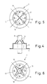
- This clamping sleeve 7 consists of a cylindrical sleeve body 8 with an outer flange 9 at one end and four inwardly directed resilient tongues 10 at the other end.
- Fig. 2 the clamping sleeve 7 is slipped as fas as the seal 2 onto the tubular prolongation 6, its resilient tongues 10 bearing on the prolongation 6 of the envelope.
- Fig. 4 shows the clamping sleeve 7 before it is placed on the prolongation 6 of the envelope
- Fig. 6 shows the clamping sleeve 7 when it has been slipped onto the prolongation 6 of the envelope. More particularly it appears from Fig. 6 that the four resilient tongues 10 of the clamping sleeve 7 engage in a point or in a line the prolongation 6 of the envelope and hold it between them.
- a tube 12 of metal provided with a light-emanating opening 11 is then introduced as a dipping cap into the cylindrical sleeve body 8 of the clamping sleeve 7 and is attached to the sleeve body 8 by welding or soldering (of. Fig. 3).
- the lamp envelope 1 is aligned on an optical bench within the assembly comprising the clamping sleeve 7 and the tube 12 in that the lamp envelope 1 is displaced in the longitudinal direction or is pivoted in the plane of the engagement points of the resilient tongues 10 of the clamping sleeve 7 on the prolongation 6 of the envelope.
- a metal disk 13 is placed on the free end of the tube 12, this disk being provided with an opening 14 for receiving the current lead-in member 4 of the lamp envelope 1.
- the metal disk 13 is then secured to the tube 12 by welding or soldering, as a result of which the lamp envelope 1 is fixed in its aligned position within the tube 12.
- the lamp envelope 1 is then still displaceable within the tube 12 in the longitudinal direction.
- a connection vane 15 is provided at the metal disk 13.
- the tube 12 is provided at its end with a few protruding lobes 16, which are arranged to surround the connection vane 15.
- the socket 17 comprises a housing portion 18 for receiving the lamp envelope 1 and a plug portion 19 for connection to an electrical current supply.
- the housing portion 18 has a cylindrical socket sleeve 20 with an integrally formed adjustment ring 21 and an inserted sealing ring 22 and serves for insertion into a corresponding fitting of a car headlight.
- a cylindrical flange bush 24 of metal is secured by means of a tubular insertion piece 23 of isolating material, for example in that the tubular insertion piece 23 of synthetic material is welded to the housing part 18 also consisting of synthetic material, as a result of which the edge 25 on the side of the bottom of the flange bush 24 is clamped between the housing part 18 and the insertion piece 23.
- the flange provided at the front edge of the flange bush 24 and projecting outwards is designated by reference numeral 26.
- the cylindrical sleeve body 8 of the clamping sleeve 7 has transverse clearance within the cylindrical flange bush 24.
- the clamping sleeve 7 with the lamp envelope 1 and the tube 12 is introduced over such a distance into the flange bush 24 that the outer flange 9 of the clamping sleeve 7 engages the flange 26 of the flange bush 24.
- the clamping sleeve 7 with the lamp envelope 1 can now be aligned - again on an optical bench - with respect to a reference axis passing through the centre of the flange bush 24 in the x and y directions (of. Fig. 8_, after which the outer flange 9 of the clamping sleeve 7 is secured to the flange 26 of the flange bush 24 by welding or soldering.
- the lamp envelope 1 Since the lamp envelope 1 is aligned within the clamping sleeve 7 and the tube 12, it is true, but is not yet fixed, it can be still be displaced over such a distance in the longitudinal direction, that is to say in the z direction, that the required light centre length L between the discharge centre and the front abutment of the adjustment ring 21 is attained. Subsequently, the current lead-in member 4 passed through the holde 14 of the metal disk 13 is secured to the connection vane 15 of the metal disk 13 by welding or soldering. The lamp envelope 1 with its tube 12 is now held at the socket 17 in a fixed and aligned position.
- the plug portion 19 of the socket 17 has a plate 17, which extends from the housing portion 18 backwards and into which two plug pins 28 and 29 are inserted, which merge into an elongate sleeve 30 for receiving the plug.
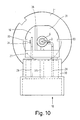
- a free spece 31 which can be closed by a removable covering hood 32, which can be inserted into guides 33 in the housing portion 18 (Fig. 10).
- the plug pin 29 to be connected to earth is connected to the current lead-in member 4 of the lamp envelope 1 through the tongue 34, the flange bush 24, the clamping sleeve 7, the tube 12 and the metal disk 13.
- the other current lead-in member 3 of the lamp envelope 1 is connected within the space 31 to the contact pin 28.
- a separation wall 35 and 36, respectively, of isolating material is provided in the sleeve 30 for receiving the plug between the plug pins 28 and 29 respectively in the space 31 between the current tongue 34 and the current lead-in member 3.
- the distance between the metal tube 12 and the lamp envelope 1 is small, i.e. with a small tube diameter, it may be advisable to provide the tube with an isolating inner coating or with a layer or with an insert of ceramic material. Thus, the risk of a demixing of the gas filling of the lamp envelope 1 can be avoided.
Abstract
Description
- The invention relates to a car headlight lamp having a lamp envelope, which has seals which are located opposite to each other and through which current lead-in members are passed to an electrical element and which is secured by means of a holding member to a socket, the holding member having a dipping cap, which at least partly surrounds the lamp envelope and is connected to a current lead-in member of the lamp envelope.
- In a car headlight high-pressure discharge lamp of this kind known from EP O 231 935 A2, the holding member has an arcuate securing body of synthetic material, which is provided with a strip of isolating material, which extends parallel to the axis of the lamp. This strip is in the form of a gutter and acts as a dipping means for obtaining an asymmetrical light distribution. On the outer side of the strip, an electrical conductor is introduced, which establishes the electrical connection between the current lead-in member of the lamp remote from the socket and a first socket contact. The other current lead-in member is connected to a second socket contact. A securing element of the holding member is inserted into a cylindrical recess of a socket consisting of synthetic material. During the manufacture, the holding member with the lamp envelope is adjustable with respect to the socket in longitudinal direction; moreover, this construction permits a slight tilting movement of the lamp envelope with respect to the socket. Because of the electrical conductors passed through the socket, however, a transverse displacement between the holding member and the socket is not possible. Moreover, the lamp envelope is then solely held by means of the comparatively sensitive current lead-in members thereof.
- Also in a car headlight lamp known from EP O 224 954 A1, the lamp envelope is held only at the current lead-in members projecting from both sides. In the later road traffic, this may lead to a bending of the current lead-in members so that the lamp envelope loses its predetermined position in the optical system.
- The invention amongst others has for its object to provide a car headlight lamp of the kind mentioned in the opening paragraph, in which the lamp envelope is held in a stable position, and in which during the manufacture a three dimensional alignment of the lamp envelope with respect to the lamp socket is possible.
- According to the invention, this object is achieved in that the socket has an outwardly projecting cylindrical flange bush for receiving the lamp envelope and the lamp envelope has a tubular prolongation, on which a clamping sleeve is placed, which comprises a cylindrical sleeve body, which has an outer flange secured to the flange bush and several inwardly directed resilient tongues, which bear on the prolongation, and in that the dipping cap is electrically conducting and is secured to the clamping sleeve.
- The lamp envelope is held by the clamping sleeve on which, before it is fixed to the cylindrical flange bush of the socket, is displaceable in transverse direction with respect thereto. Moreover, the clamping sleeve carries the dimming hood, which surrounds the lamp envelope, is electrically conducting and establishes at its free end the electrical connection with the current lead-in member of the free end of the lamp envelope. As a result thereof a mechanical support of the free end of the lamp envelope is obtained, too. Thus, the lamp envelope is held in a reliable manner at a stable envelope portion. During the manufacture, the lamp envelope can be aligned in all directions with respect to a reference axis or reference plane.
- If the dipping cap should serve as a mechanical protection for the lamp envelope too, according to a further embodiment of the invention, it is constructed as a tube. Said tube surrounds the lamp envelope, is provided with at least one light emanating opening and is introduced by one end into the cylindrical sleeve body of the clamping sleeve and is closed at the free end by a disk provided with an opening for receiving the respective current lead-in member.
- A particularly stable construction occupying little space is obtained if according to a further embodiment of the invention the clamping sleeve with its sleeve body projects into the flange bush with transverse clearance. Also in this case, during the manufacture of the lamp the clamping sleeve can be displaced in the cylindrical flange bush in all directions transverse to a reference axis extending through the centre of the flange bush. The mounting of the lamp is further facilitated if according to an advantageous embodiment of the invention the flange bush, the clamping sleeve and the dipping cap with its disk consist of metal and the parts are welded or soldered to each other.
- The headlight lamp may be an incandescent lamp, the electrical element being an incandescent body. If in the car headlight lamp according to the invention a discharge lamp having a gas-filled lamp envelope, housing a pair of electrodes as the elctrical element is used, a demixing of the gas filling may occur when surrounding the lamp envelope by a metal tube. In order to avoid this, according to a further embodiment of the invention, the metallic tube can have an electrically isolating coating on the inner side thereof, that is the side directed towards the lamp envelope.
- The invention also relates to a method of manufacturing the car headlight lamp of the invention. According to the invention, this method is characterized in that first a clamping sleeve comprising a cylindrical sleeve body having an outer flange and several inwardly directed resilient tongues, is palced on a tubular prolongation of the lamp envelope, the dipping cap is secured to the clamping sleeve, the lamp envelope is aligned with respect to the clamping sleeve and the dipping cap and a disk provided with an opening is slipped over a current lead-in member and is connected to the free end of the dipping cap, after which the clamping sleeve is caused to engage by its outer flange the flange of the flange bush and is aligned in the contact plane thereof, whereupon the two flanges are secured to each other, and in that subsequently, as the case may be after a further alignment of the lamp envelope by displacement thereof with respect to the dipping cap, the current lead-in member of the lamp envelope remote from the socket is rigidly secured to the dimming hood.
- In order that the invention may be readily carried out, it will now be described more fully with reference to the accompanying drawing, in which:
- Figures 1 to 3 show different processing steps in the manufacture of a car headlight lantern,
- Fig. 4 shows on an enlarged scale a sectional view of a clamping sleeve slipped onto a tubular prolongation of the lamp envelope,
- Fig. 5 is the rear view of the clamping sleeve before it is placed on the prolongation of the lamp envelope,
- Fig. 6 is a corresponding rear view of the clamping sleeve after it has been placed on the prolongation of the lamp envelope,
- Fig. 7 is a side elevation of a lamp socket,
- Fig. 8 is a side elevation of a mounted car headlight lantern,
- Fig. 9 shows on an enlarged scale a longitudinal sectional view of the car headlight lantern shown in Fig. 8, and
- Fig. 10 shows the rear view of the car headlight lantern shown in Fig. 9, of which the dimming hood is removed.
- Fig. 1 shows the
lamp envelope 1 of a high-pressure gas discharge lamp, which hasseals 2, which are located opposite to each other and through which current lead-inmembers electrical element 5. These current lead-inmembers electrodes 5 within thelamp envelope 1. Thelamp envelope 1 is filled with a gas, which besides mercury comprises metal halide, for example sodium iodide. The discharge space has a content of about 130 mm³. Thelamp envelope 1 has atubular prolongation 6. Thelamp envelope 1 and thetubular prolongation 6 consist, for example, of quartz glass. During the manufacture of the headlight lamp, first aclamping sleeve 7 consisting, for example, of resilient metal is placed on thetubular prolongation 6 of thelamp envelope 1. Thisclamping sleeve 7 consists of acylindrical sleeve body 8 with anouter flange 9 at one end and four inwardly directedresilient tongues 10 at the other end. - In Fig. 2, the
clamping sleeve 7 is slipped as fas as theseal 2 onto thetubular prolongation 6, itsresilient tongues 10 bearing on theprolongation 6 of the envelope. This is shown in Fig. 4 on an enlarged scale. Fig. 5 shows theclamping sleeve 7 before it is placed on theprolongation 6 of the envelope and Fig. 6 shows theclamping sleeve 7 when it has been slipped onto theprolongation 6 of the envelope. More particularly it appears from Fig. 6 that the fourresilient tongues 10 of theclamping sleeve 7 engage in a point or in a line theprolongation 6 of the envelope and hold it between them. - According to Fig. 2, a
tube 12 of metal provided with a light-emanatingopening 11 is then introduced as a dipping cap into thecylindrical sleeve body 8 of theclamping sleeve 7 and is attached to thesleeve body 8 by welding or soldering (of. Fig. 3). Subsequently, thelamp envelope 1 is aligned on an optical bench within the assembly comprising theclamping sleeve 7 and thetube 12 in that thelamp envelope 1 is displaced in the longitudinal direction or is pivoted in the plane of the engagement points of theresilient tongues 10 of theclamping sleeve 7 on theprolongation 6 of the envelope. After this alignment operation, ametal disk 13 is placed on the free end of thetube 12, this disk being provided with anopening 14 for receiving the current lead-inmember 4 of thelamp envelope 1. Themetal disk 13 is then secured to thetube 12 by welding or soldering, as a result of which thelamp envelope 1 is fixed in its aligned position within thetube 12. Thelamp envelope 1 is then still displaceable within thetube 12 in the longitudinal direction. In order to allow later securing the current lead-inmember 4, aconnection vane 15 is provided at themetal disk 13. In order to protect thisconnection vane 15 from external damage, thetube 12 is provided at its end with a few protrudinglobes 16, which are arranged to surround theconnection vane 15. - Subsequently, the
lamp envelope 1 held in theclamping sleeve 7 and thetube 12 is inserted into a socket 17 (Fig. 7) (cf. Fig. 8). As appears more particularly from Figures 9 and 10, thesocket 17 comprises ahousing portion 18 for receiving thelamp envelope 1 and aplug portion 19 for connection to an electrical current supply. Thehousing portion 18 has acylindrical socket sleeve 20 with an integrally formedadjustment ring 21 and an insertedsealing ring 22 and serves for insertion into a corresponding fitting of a car headlight. In thesocket sleeve 20, acylindrical flange bush 24 of metal is secured by means of atubular insertion piece 23 of isolating material, for example in that thetubular insertion piece 23 of synthetic material is welded to thehousing part 18 also consisting of synthetic material, as a result of which theedge 25 on the side of the bottom of theflange bush 24 is clamped between thehousing part 18 and theinsertion piece 23. The flange provided at the front edge of theflange bush 24 and projecting outwards is designated byreference numeral 26. Thecylindrical sleeve body 8 of theclamping sleeve 7 has transverse clearance within thecylindrical flange bush 24. Theclamping sleeve 7 with thelamp envelope 1 and thetube 12 is introduced over such a distance into theflange bush 24 that theouter flange 9 of theclamping sleeve 7 engages theflange 26 of theflange bush 24. The clampingsleeve 7 with thelamp envelope 1 can now be aligned - again on an optical bench - with respect to a reference axis passing through the centre of theflange bush 24 in the x and y directions (of. Fig. 8_, after which theouter flange 9 of the clampingsleeve 7 is secured to theflange 26 of theflange bush 24 by welding or soldering. Since thelamp envelope 1 is aligned within the clampingsleeve 7 and thetube 12, it is true, but is not yet fixed, it can be still be displaced over such a distance in the longitudinal direction, that is to say in the z direction, that the required light centre length L between the discharge centre and the front abutment of theadjustment ring 21 is attained. Subsequently, the current lead-inmember 4 passed through theholde 14 of themetal disk 13 is secured to theconnection vane 15 of themetal disk 13 by welding or soldering. Thelamp envelope 1 with itstube 12 is now held at thesocket 17 in a fixed and aligned position. - The
plug portion 19 of thesocket 17 has aplate 17, which extends from thehousing portion 18 backwards and into which two plug pins 28 and 29 are inserted, which merge into anelongate sleeve 30 for receiving the plug. Above theplate 27 is arranged afree spece 31, which can be closed by aremovable covering hood 32, which can be inserted intoguides 33 in the housing portion 18 (Fig. 10). - Not only the two plug pins 28 and 29 as well as the
tubular prolongation 6 of thelamp envelope 1 with the current lead-inmember 3, but also atongue 34 of electrically conducting material connected to theedge 25 of theflange bush 24 and connected in thespace 31 to theplug pin 29 merge into thisspace 31. Thus, theplug pin 29 to be connected to earth is connected to the current lead-inmember 4 of thelamp envelope 1 through thetongue 34, theflange bush 24, the clampingsleeve 7, thetube 12 and themetal disk 13. The other current lead-inmember 3 of thelamp envelope 1 is connected within thespace 31 to thecontact pin 28. Since for operation of a car headlight high-pressure discharge lamp transient voltages up to 15 kV are required, aseparation wall sleeve 30 for receiving the plug between the plug pins 28 and 29 respectively in thespace 31 between thecurrent tongue 34 and the current lead-inmember 3. - If the distance between the
metal tube 12 and thelamp envelope 1 is small, i.e. with a small tube diameter, it may be advisable to provide the tube with an isolating inner coating or with a layer or with an insert of ceramic material. Thus, the risk of a demixing of the gas filling of thelamp envelope 1 can be avoided.
Claims (6)
Applications Claiming Priority (2)
| Application Number | Priority Date | Filing Date | Title |
|---|---|---|---|
| DE3837511 | 1988-11-04 | ||
| DE3837511A DE3837511A1 (en) | 1988-11-04 | 1988-11-04 | MOTOR VEHICLE HEADLAMP LAMP AND METHOD FOR THEIR PRODUCTION |
Publications (2)
| Publication Number | Publication Date |
|---|---|
| EP0367343A2 true EP0367343A2 (en) | 1990-05-09 |
| EP0367343A3 EP0367343A3 (en) | 1991-04-17 |
Family
ID=6366523
Family Applications (1)
| Application Number | Title | Priority Date | Filing Date |
|---|---|---|---|
| EP19890202725 Ceased EP0367343A3 (en) | 1988-11-04 | 1989-10-30 | Car headlight lamp and method of manufacturing same |
Country Status (5)
| Country | Link |
|---|---|
| US (1) | US5036439A (en) |
| EP (1) | EP0367343A3 (en) |
| JP (1) | JPH02172156A (en) |
| DE (1) | DE3837511A1 (en) |
| HU (1) | HU202332B (en) |
Cited By (9)
| Publication number | Priority date | Publication date | Assignee | Title |
|---|---|---|---|---|
| EP0580013A1 (en) * | 1992-07-17 | 1994-01-26 | Patent-Treuhand-Gesellschaft für elektrische Glühlampen mbH | Single-ended high pressure discharge lamp |
| WO1997006385A1 (en) * | 1995-08-04 | 1997-02-20 | General Electric Company | Metal strap for holding cylindrical lamp |
| EP0989591A1 (en) * | 1998-09-23 | 2000-03-29 | Patent-Treuhand-Gesellschaft für elektrische Glühlampen mbH | Electric lamp |
| WO2001039237A1 (en) * | 1999-11-20 | 2001-05-31 | Ist Metz Gmbh | Connector system for a rod-shaped two-ended discharge lamp |
| DE102005007659A1 (en) * | 2005-02-19 | 2006-08-24 | Hella Kgaa Hueck & Co. | Ignition torch, for gas discharge lamp, especially for motor vehicle headlights, has discharge chamber with arc generating electrodes and joined piece integrated with end of chamber |
| WO2006136994A2 (en) * | 2005-06-24 | 2006-12-28 | Philips Intellectual Property & Standards Gmbh | Gas-discharge lamp and method of manufacturing the same |
| WO2008110969A2 (en) | 2007-03-12 | 2008-09-18 | Philips Intellectual Property & Standards Gmbh | High pressure discharge lamp |
| ITTO20080626A1 (en) * | 2008-08-07 | 2010-02-08 | Tyco Electronics Amp Italia S P A | CONNECTOR DEVICE TO CONNECT AN ELECTRODE OF A LAMP WITH A FLUORESCENT TUBE TO A POWER CABLE |
| WO2011033417A3 (en) * | 2009-09-18 | 2011-05-19 | Koninklijke Philips Electronics N.V. | An apparatus for fastening the burner of a discharge lamp |
Families Citing this family (12)
| Publication number | Priority date | Publication date | Assignee | Title |
|---|---|---|---|---|
| US5216319A (en) * | 1990-09-26 | 1993-06-01 | U.S. Philips Corporation | Capped high-pressure discharge lamp |
| DE69106996D1 (en) * | 1990-09-28 | 1995-03-09 | Philips Electronics Nv | Socketed high-pressure discharge lamp and lamp holder for this lamp. |
| US5510967A (en) * | 1994-12-13 | 1996-04-23 | Osram Sylvania Inc. | Hid headlamp assembly |
| US5890123A (en) * | 1995-06-05 | 1999-03-30 | Lucent Technologies, Inc. | System and method for voice controlled video screen display |
| US5659221A (en) * | 1996-03-26 | 1997-08-19 | Osram Sylvania, Inc. | High intensity discharge headlamp assembly |
| JP3183831B2 (en) * | 1996-07-12 | 2001-07-09 | ヒロセ電機株式会社 | Lamp socket |
| FR2862744B1 (en) * | 2003-11-21 | 2006-09-29 | Valeo Vision | SYSTEM FOR FIXING A LIGHT SOURCE ON A COUNTERPART OF A MOTOR VEHICLE PROJECTOR AND METHOD FOR CARRYING OUT SAID METHOD |
| DE10358361A1 (en) * | 2003-12-12 | 2005-07-07 | Patent-Treuhand-Gesellschaft für elektrische Glühlampen mbH | Holding device for fixing a lamp bulb and associated lamp |
| DE102004004651B3 (en) * | 2004-01-29 | 2005-12-01 | Flowil International Lighting (Holding) B.V. | Lamp for general lighting purposes |
| DE102004007150A1 (en) * | 2004-02-12 | 2005-08-25 | Patent-Treuhand-Gesellschaft für elektrische Glühlampen mbH | Base for a headlamp and headlamp |
| CN101657880A (en) * | 2007-04-13 | 2010-02-24 | 皇家飞利浦电子股份有限公司 | The manufacture method of lamp, lamp and retainer is used for the purposes of this lamp |
| US9753242B2 (en) * | 2013-11-27 | 2017-09-05 | Bae Systems Information And Electronic Systems Integration Inc. | Optical bench assembly |
Citations (2)
| Publication number | Priority date | Publication date | Assignee | Title |
|---|---|---|---|---|
| US4569005A (en) * | 1985-01-15 | 1986-02-04 | Gte Products Corporation | Replaceable lamp unit and automobile headlight utilizing same |
| EP0231935A2 (en) * | 1986-02-06 | 1987-08-12 | Patent-Treuhand-Gesellschaft für elektrische Glühlampen mbH | Dazzle headlight lamp for motor vehicles |
Family Cites Families (5)
| Publication number | Priority date | Publication date | Assignee | Title |
|---|---|---|---|---|
| US3050619A (en) * | 1959-10-02 | 1962-08-21 | Raylite Electric Corp | Display outfits with separable decorative floral cover constructions |
| GB1221946A (en) * | 1967-08-16 | 1971-02-10 | Lucas Industries Ltd | Sealed beam lamps |
| US4754373A (en) * | 1986-10-14 | 1988-06-28 | General Electric Company | Automotive headlamp |
| DE3641852A1 (en) * | 1986-12-08 | 1988-06-16 | Patent Treuhand Ges Fuer Elektrische Gluehlampen Mbh | VEHICLE HEADLIGHT UNIT |
| NL8801326A (en) * | 1987-09-24 | 1989-04-17 | Philips Nv | SOCKET ELECTRIC LAMP. |
-
1988
- 1988-11-04 DE DE3837511A patent/DE3837511A1/en not_active Withdrawn
-
1989
- 1989-10-30 EP EP19890202725 patent/EP0367343A3/en not_active Ceased
- 1989-11-01 HU HU895635A patent/HU202332B/en unknown
- 1989-11-02 JP JP1285115A patent/JPH02172156A/en active Pending
- 1989-11-06 US US07/433,063 patent/US5036439A/en not_active Expired - Fee Related
Patent Citations (2)
| Publication number | Priority date | Publication date | Assignee | Title |
|---|---|---|---|---|
| US4569005A (en) * | 1985-01-15 | 1986-02-04 | Gte Products Corporation | Replaceable lamp unit and automobile headlight utilizing same |
| EP0231935A2 (en) * | 1986-02-06 | 1987-08-12 | Patent-Treuhand-Gesellschaft für elektrische Glühlampen mbH | Dazzle headlight lamp for motor vehicles |
Cited By (20)
| Publication number | Priority date | Publication date | Assignee | Title |
|---|---|---|---|---|
| EP0580013A1 (en) * | 1992-07-17 | 1994-01-26 | Patent-Treuhand-Gesellschaft für elektrische Glühlampen mbH | Single-ended high pressure discharge lamp |
| US5428261A (en) * | 1992-07-17 | 1995-06-27 | Patent-Treuhand-Gesellschaft F. Elektrische Gluehlampen Mbh | Single-ended, plastic-based high-pressure discharge lamp |
| WO1997006385A1 (en) * | 1995-08-04 | 1997-02-20 | General Electric Company | Metal strap for holding cylindrical lamp |
| US5684355A (en) * | 1995-08-04 | 1997-11-04 | General Electric Company | Metal strap for holding cylindrical lamp |
| EP0989591A1 (en) * | 1998-09-23 | 2000-03-29 | Patent-Treuhand-Gesellschaft für elektrische Glühlampen mbH | Electric lamp |
| US6210021B1 (en) | 1998-09-23 | 2001-04-03 | Patent-Treuhand-Gesellschaft Fuer Elektrische Gluehlampen Mbh | Electric lamp with rotatable base including compressed contacts |
| WO2001039237A1 (en) * | 1999-11-20 | 2001-05-31 | Ist Metz Gmbh | Connector system for a rod-shaped two-ended discharge lamp |
| DE102005007659A1 (en) * | 2005-02-19 | 2006-08-24 | Hella Kgaa Hueck & Co. | Ignition torch, for gas discharge lamp, especially for motor vehicle headlights, has discharge chamber with arc generating electrodes and joined piece integrated with end of chamber |
| WO2006136994A2 (en) * | 2005-06-24 | 2006-12-28 | Philips Intellectual Property & Standards Gmbh | Gas-discharge lamp and method of manufacturing the same |
| WO2006136994A3 (en) * | 2005-06-24 | 2007-10-11 | Philips Intellectual Property | Gas-discharge lamp and method of manufacturing the same |
| WO2008110969A2 (en) | 2007-03-12 | 2008-09-18 | Philips Intellectual Property & Standards Gmbh | High pressure discharge lamp |
| WO2008110969A3 (en) * | 2007-03-12 | 2009-07-23 | Philips Intellectual Property | High pressure discharge lamp |
| CN101641759B (en) * | 2007-03-12 | 2013-05-22 | 皇家飞利浦电子股份有限公司 | High pressure discharge lamp |
| US9033564B2 (en) | 2007-03-12 | 2015-05-19 | Koninklijke Philips N.V. | High pressure discharge lamp |
| ITTO20080626A1 (en) * | 2008-08-07 | 2010-02-08 | Tyco Electronics Amp Italia S P A | CONNECTOR DEVICE TO CONNECT AN ELECTRODE OF A LAMP WITH A FLUORESCENT TUBE TO A POWER CABLE |
| WO2010015946A1 (en) | 2008-08-07 | 2010-02-11 | Tyco Electronics Amp Italia S.P.A. | Connector device for connecting a cold cathode of a neon or fluorescent-tube lamp to a supply cable |
| WO2011033417A3 (en) * | 2009-09-18 | 2011-05-19 | Koninklijke Philips Electronics N.V. | An apparatus for fastening the burner of a discharge lamp |
| CN102388428A (en) * | 2009-09-18 | 2012-03-21 | 皇家飞利浦电子股份有限公司 | An apparatus for fastening the burner of a discharge lamp |
| US8692465B2 (en) | 2009-09-18 | 2014-04-08 | Koninklijke Philips N.V. | Apparatus for fastening the burner of a discharge lamp |
| CN102388428B (en) * | 2009-09-18 | 2015-02-25 | 皇家飞利浦电子股份有限公司 | An apparatus for fastening the burner of a discharge lamp |
Also Published As
| Publication number | Publication date |
|---|---|
| HU895635D0 (en) | 1990-01-28 |
| EP0367343A3 (en) | 1991-04-17 |
| JPH02172156A (en) | 1990-07-03 |
| HU202332B (en) | 1991-02-28 |
| DE3837511A1 (en) | 1990-05-10 |
| HUT51789A (en) | 1990-05-28 |
| US5036439A (en) | 1991-07-30 |
Similar Documents
| Publication | Publication Date | Title |
|---|---|---|
| US5036439A (en) | Car headlight lamp and method of manufacturing same | |
| US4687965A (en) | Capped electric lamp | |
| US4138621A (en) | Short-arc discharge lamp with starting device | |
| US3622832A (en) | Interchangeable tungsten halogen lamp | |
| US4823049A (en) | Vehicle lamp having a molded lamp cap with integral current-supply conductors and dipping cap | |
| US4241391A (en) | Inner lamp-mount assembly for sealed-beam headlamp and similar lighting apparatus | |
| HUT59257A (en) | High-pressure discharge lamp with cap and socket belonging thereto | |
| US4126810A (en) | Ceramic base for glass halogen lamps | |
| US4012658A (en) | Electric lamps mounted in a flanged cap | |
| US4316240A (en) | Inner lamp mount assembly for vehicular headlamp and similar lighting apparatus | |
| US2795724A (en) | Electric discharge lamps | |
| EP1062680B1 (en) | Lamp with protective sleeve | |
| EP0152649A1 (en) | Electrical lamp having a lamp cap of synthetic material | |
| US3746906A (en) | Adapter base for electric lamp | |
| US4542316A (en) | Discharge lamps | |
| US5785543A (en) | High voltage flashlamp connector method and apparatus | |
| US5457354A (en) | Lamp with improved mount for light-source capsule | |
| US5440196A (en) | Dual-envelope high-pressure discharge lamp construction, and method of its manufacture | |
| US6369504B1 (en) | Low pressure mercury vapor discharge lamp | |
| JPS6134849A (en) | Electric lamp | |
| US4292564A (en) | Lamp/reflector unit | |
| CA1111811A (en) | Lamp/reflector unit | |
| CN101416272A (en) | High-pressure discharge lamp assembly | |
| KR100712745B1 (en) | Electric lamp | |
| GB2100503A (en) | Discharge lamps |
Legal Events
| Date | Code | Title | Description |
|---|---|---|---|
| PUAI | Public reference made under article 153(3) epc to a published international application that has entered the european phase |
Free format text: ORIGINAL CODE: 0009012 |
|
| AK | Designated contracting states |
Kind code of ref document: A2 Designated state(s): BE DE ES FR GB IT NL SE |
|
| PUAL | Search report despatched |
Free format text: ORIGINAL CODE: 0009013 |
|
| AK | Designated contracting states |
Kind code of ref document: A3 Designated state(s): BE DE ES FR GB IT NL SE |
|
| 17P | Request for examination filed |
Effective date: 19911014 |
|
| 17Q | First examination report despatched |
Effective date: 19930923 |
|
| STAA | Information on the status of an ep patent application or granted ep patent |
Free format text: STATUS: THE APPLICATION HAS BEEN REFUSED |
|
| 18R | Application refused |
Effective date: 19940320 |