EP0368347A2 - Disk Cartridge - Google Patents
Disk Cartridge Download PDFInfo
- Publication number
- EP0368347A2 EP0368347A2 EP89120901A EP89120901A EP0368347A2 EP 0368347 A2 EP0368347 A2 EP 0368347A2 EP 89120901 A EP89120901 A EP 89120901A EP 89120901 A EP89120901 A EP 89120901A EP 0368347 A2 EP0368347 A2 EP 0368347A2
- Authority
- EP
- European Patent Office
- Prior art keywords
- main body
- cartridge
- opening
- aperture
- disk
- Prior art date
- Legal status (The legal status is an assumption and is not a legal conclusion. Google has not performed a legal analysis and makes no representation as to the accuracy of the status listed.)
- Granted
Links
- 230000013011 mating Effects 0.000 claims abstract description 23
- 238000003780 insertion Methods 0.000 claims description 35
- 230000037431 insertion Effects 0.000 claims description 35
- 230000003287 optical effect Effects 0.000 abstract description 14
- 229940090045 cartridge Drugs 0.000 abstract 4
- 238000001746 injection moulding Methods 0.000 description 2
- 239000000463 material Substances 0.000 description 2
- 229920003002 synthetic resin Polymers 0.000 description 2
- 239000000057 synthetic resin Substances 0.000 description 2
- 230000008021 deposition Effects 0.000 description 1
- 239000000428 dust Substances 0.000 description 1
- 230000000717 retained effect Effects 0.000 description 1
- 229910001220 stainless steel Inorganic materials 0.000 description 1
- 239000010935 stainless steel Substances 0.000 description 1
- 230000002459 sustained effect Effects 0.000 description 1
Images


Classifications
-
- G—PHYSICS
- G11—INFORMATION STORAGE
- G11B—INFORMATION STORAGE BASED ON RELATIVE MOVEMENT BETWEEN RECORD CARRIER AND TRANSDUCER
- G11B23/00—Record carriers not specific to the method of recording or reproducing; Accessories, e.g. containers, specially adapted for co-operation with the recording or reproducing apparatus ; Intermediate mediums; Apparatus or processes specially adapted for their manufacture
- G11B23/02—Containers; Storing means both adapted to cooperate with the recording or reproducing means
- G11B23/03—Containers for flat record carriers
- G11B23/0301—Details
- G11B23/0317—Containers with interchangeable record carriers
Definitions
- This invention relates to a disk cartridge for exchangeably accomodating a disk-shaped recording medium, such as an optical disk or magneto-optical disk.
- a disk shaped recording medium such as a write-once type optical disk
- This type of the disk is accommodated in a disk cartridge when attached to the recording and/or reproducing apparatus with a view mainly to preventing data signal record and/or reproduce errors caused by the signal recording surface being injured or contaminated due to contact directly with part of a loading mechanism or due to contact of hand or finger or deposition of dust and dirt during insertion into or detachment from the recording and/or reproducing apparatus.
- the present Assignee has already proposed an arrangement shown in the spesification and drawings of the Japanese laid open Patent Publication No. 57970/1988 or an arrangement shown in the specification and drawings of the Japanese Utility Model Application No. 86810/1988.
- the disk cartridge shown in these specifications and drawings is so arranged that a lid is provided at a disk insertion/detachment aperture formed in the rear surface of the main body of the cartridge accommodating the disk opposite to its front surface or shutter attachment surface for opening or closing the aperture, and that this lid is opened to enable disk exchange.
- the lid has an L-shaped cross-section for closing the disk insertion/attachment aperture extending from the upper rear surface towards the lateral rear surface of the main body of the cartridge, and is pivotally connected to the rear parts of the lateral walls of the main cartridge body by pivoltal engagement between pivot pins and engaging recesses, so as to be rotated in a direction normal to the plane of the main body of the cartridge.
- the aperture opening/closing lid has an engaging recess on the lower inner rear surface which may be engaged with a mating projection on the rear edge of the main body of the cartridge when the lid is brought to a position of closing the disk insertion/detachment aperture.
- disk exchange may be made upon opening and closing the aperture opening/closing lid, while the disk cartridge may be attached to the recording and/or reproducing apparatus in the similar manner to the ordinary disk cartridge by closing the disk insertion/detachment aperture by the opening/closing lid.
- the aperture opening/closing lid of the above described disk cartridge is rotatably supported by the main body of the cartridge by means of pivots on its both sides, so that a thrust pressure is necessarily applied to the central flat surface section intermediate both side pivots when the lid is opened by disengaging the engaging recess away from the mating projection of the main body of the cartridge.
- a thrust pressure is necessarily applied to the central flat surface section intermediate both side pivots when the lid is opened by disengaging the engaging recess away from the mating projection of the main body of the cartridge.
- the disk cartridge of the present invention includes a main body of the cartridge provided with an opening for exposing the signal recording surface of an accommodated disk-shaped recording medium to outside, and also with an insertion/detachment aperture for the disk-shaped recording medium on its side normal to the main surface in which the opening is formed, and a shutter slidably mounted to the main body of the cartridge for opening or closing the opening.
- the disk cartridge also includes an aperture opening/closing member which is rotatably supported by the main body of the cartridge by having a pivot section pivotally connected to one end of the disk insertion/detachment aperture in the main body of the cartridge to open or close the apertuere, and which is provided at the side opposite to the pivot section with a resilient arm having a retaining end pawl engaging with a mating retaining section in the main body of the cartridge.
- the disk cartridge according to the present invention also includes a position control section at the one side provided with the pivot section adapted for pivotally connecting the aperture opening/closing member to the main body of the cartridge.
- the position control section is adapted to engage with a portion of the main body of the cartridge.
- the disk cartridge of the present invention is so designed that the aperture opening/closing member supported by the main body of the cartridge by means of the pivot section is rotated within a plane parallel to the plane of the main body of the cartridge, that is, within the major surface thereof, for opening or closing the disk insertion/detachment opening in the main body of the cartridge.
- the control section engages with a portion of the main body of the cartridge for locking the opening/closing member to the main body of the cartridge.
- the aperture opening/closing member which is in the state of closing the disk insertion/detachment aperture, may be unlocked from the main body of the cartridge by flexing the resilient arm and disengaging the retaining end pawl thereof from the mating retaining section of the main body.
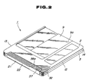
- the disk cartridge of the present invention includes a main body of the cartridge 1 formed by an upper half 2 and a lower half 3 abutted and connected to each other. These halves 2 and 3 are each in the form of a flat rectangular plate which is formed by, for example, injection molding of a suitable synthetic resin material. Within this main body of the cartridge 1 is rotatabaly enclosed an optical disk 4 provided with a disk-shaped recording medium, such as a write-once type optical recording medium.
- substantially rectangular openings 7 and 8 Extending from the central sections towards the front edges of the upper and lower halves 2 and 3 of the main body 1 are substantially rectangular openings 7 and 8 which are adapted for exposing a central chucking section of an optical disk 4 accommodated therein and the signal recording surface of the optical disk 4 towards outside and which are faced by data signal recording/reproducing means, such as an optical pickup, adapted to record or reproduce data signals on or from the disk 4.
- a shutter 9 for opening or closing the openings 7 and 8 is slidably mounted on the main body of the cartridge 1.
- This shutter 9 is formed by a thin metallic plate, such as a stainless steel plate, which is bent into the form of a letter U, and is made up of a first closure section 9a for closing the opening 7 in the upper half 2, a second closure section 9b for closing the opening 8 in the lower half 3 and a connecting section 9c for connecting these closure sections 9a and 9b to each other.
- a thin metallic plate such as a stainless steel plate
- the shutter 9 is fitted from the front side over the outer surfaces of the main body of the cartridge 1, with the first and the second closure sections 9a and 9b extending over the openings 7 and 8 in the flat surface of the closure members 9a and 9b and sliding on the flat surfaces of the main body of the cartridge 1.
- substantially circular recesses 10 each having an inside diameter slightly larger than the outside diameter of the optical disk 4.
- the recesses 10 are delimited towards the front side by arcuate ribs 11 formed on the inner surfaces of the upper and lower halves 2 and 3. These ribs are formed upright on the bottom surfaces of the recesses 10 and of such a height that the ribs abut on each other when the upper and the lower halves 2 and 3 are combined together to form the main body of the cartridge 1.
- These arcuate ribs 11 are abutted to each other to form a forward wall of the main body of the cartridge 1.
- the recesses 10 are abutted to each other to form a disk accommodating section 6 when the upper and the lower halves 2 and 3 are abutted and connected to each other.
- the rear side of the main body of the cartridge 1 opposite to its front side fitted with the shutter 9, is free from closure walls such as upright walls or arcuate ribs and thus in the completely opened state.
- An opening/closing member 21 is provided on the main body of the cartridge 1 for opning or closing the disk insertion/detachment aperture 20.
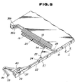
- This opening/closing member 21 in formed by, for example, injection molding the same synthetic resin material as that of the upper and the lower halves 2 and 3, as shown in Figs. 1 and 5.
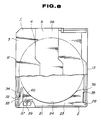
- the opening/closing member 21 is formed by a side wall section 22 forming the rear side wall of the main body of the cartridge 1 when the member 21 is inserted into the aperture 20 for closing the aperture 20 as shown in Figs. 2 and 8, and a fitting section 23 projecting from one lateral side of the side wall section 22 and adapted for intruding into the inside of the main body of the cartridge 1 for defining the disk accommodating section 6.
- the side wall section 22 is of the same height and width as the disk insertion/detachment aperture 20.
- the fitting section 23 forms the rear side wall of the disk accommodating section 6 when the opening/closing member 21 is inserted into the disk inserting/detachment aparture 20. For this reason, an arcuate recess 24 is formed on the distal side of the fitting section 23 so as to be contiguous to the substantially arcuate recess 10 of the upper and the lower halves 2 and 3.
- a projection 26 is provided at one corner of the aperture opening/closing member 21 along the extending direction of the side wall section 22, and pivot pins 27, 28 are provided upright on the upper and the lower sides of the proejction 26. These pivot pins 27, 28 are engaged in mating recesses 29, 30 at the corresponding rear side corners of the upper and the lower halves 2 and 3, as shown in Fig. 7, to form a pivot section 31 for rotatably supporting the aperture opening/closing member 21 with respect to the main body 1.
- the aperture opening/closing member 21, thus supported by the main body 1 may be rotated within a plane parallel to the plane of the main body 1, with the pivot section 31 as the center of rotation, as shown in Fig. 6.
- the pivoting section 31, pivotally supporting the aperture opening/closing member 21, may be so designed that, conversely to the above mentioned arrangement, the pivot pins 27, 28 are formed on the upper and lower halves 2 and 3 and the mating recesses 29, 30 are formed in the projection 26.
- the other side of the aperture opening/closing member 21, opposite to the side thereof provided with the pivot pins 27, 28, is formed with a resilient arm 34 having a retaining end pawl 33 engaging with a mating hole 32 which is formed in the other lateral wall 13 of the main body of the cartridge 1 and which is adapted for functioning as a retaining section.
- this resilient arm 34 is formed integrally with the other end of the fitting section 23 for extending from the end of the fitting section 23 towards the side wall section 22 and may be resiliently deformed with the connecting point to the fitting section 23 as the fulcrum.
- the one end of the aperture opening/closing member 21 is provided with a position control section 36 which is formed as a boss extending parallel to the pivot pins 27, 28 and adapted for engaging in a mating recess 35 in the inner lateral side of the lateral wall 12 of the main body of the cartridge 1.
- This boss 36 is formed for projecting laterally from the one end of the fitting section 23.
- This position control member 36 need only be of such a contour that the member 36 is engaged with a mating engaging portion of the main of the cartridge 1 to control the rotational position of the aperture opening/closing member 21.
- the member 36 may be in various forms, such as a pawl or finger, mating in a corresponding engaging portion of the main body of the cartridge 1.
- the other end of the side wall section 22 of the aperture opening/closing member 21 is provided with a generally trapezoidal gripping section 37 adapted for facilitating the rotation of the aperture opening/closing member 21 and having the same thickness as the thickness of the main body 1.
- the gripping section 37 fits into mating recesses 38a, 38b on the rear side edges of the upper and lower halves 2 and 3 of the main body 1 so as to be flush with the surfaces of the upper and the lower halves 2 and 3.
- a post recording inhibit member 39 On the lower side of the gripping section 37 having the above thickness, that is, on the side thereof which will the lower half 3 on attachment of the member 21 to the main body of the cartridge 1, there is provided a post recording inhibit member 39, as shown in Fig. 5 and 6.
- This post-recording inhibit member 39 is slidably mounted in an engaging hole 40 in the gripping section 37 for movement therein, so that, when the disk cartridge is attached to the recording and/or reproducing apparatus, it can be detected at the apparatus whether the post recording of data signals may be made on the optical disk 4 or such post-recording is inhibited.
- the above described aperture opening/closing member 21 is rotatably supported by the main body of the cartridge 1 by having the pivot pins 27, 28 engaging in the mating recesses 29, 30 of the upper and the lower halves 2 and 3, as shown in Figs. 5 and 6.
- the fitting section 23 is rotated into fitting with the disk insertion/detachment aperture 20, that is, in the direction shown by an arrow B in Fig. 6, the resilient arm 34 intrudes into the disk insertion/detachment aperture 20, as the resilient arm 34 is resiliently deformed by the inner surface of the other side wall 13 of the main body 1.
- the arm 34 is resiliently restored, as shown in Fig.
- the retaining end pawl 33 then engaging in the mating hole 32 for locking the opening/closing member 21 to the main body 1.
- the position control section 36 provided at the one end of the opening/ closure member 21 engages with the engaging hole 35 in the inner lateral surface of the lateral wall 12 of the main body 1.
- the side wall section 22 engages with mating steps 18, 19 formed on the inner surface at the rear side of the upper and the lower halves 2 and 3 for completely closing the disk insertion/detachment aperture 20.
- the aperture opening/closing member 21, which is locked to the main body of the cartridge 1 in this manner for closing the disk insertion/ detachment aperture 20, may be fitted in the precisely controlled position with respect to the main body of the cartridge 1 by the retaining end pawl 33 and the position control section 36, as shown in Fig. 8.
- the position control section 36 is provided at the side of the opening/closing member 21 provided with the pivot section 31, any load applied to the aperture opening/closing member 21 may be received by the position control section 36 to prevent an excess load from being applied to the pivot section 31. This results in the pivot section 31 being protected from application of external forces or pressures.
- a thrust tool such as a pin
- the resilient arm 34 is introduced via the hole 32 to cause the resilient arm 34 to be deformed resiliently to disengate the end pawl 33 out of the mating hole 32.
- the gripping section 37 is gripped to rotate the aperture opening/closing member 21 in the direction shown by an arrow A in Fig. 6 to expose the disk insertion/detachment aperture 20.
- the optical disk 4 may be exchanged by way of the aperture 20.
- the inclined guide surfaces 41, 42 function to disengage the pivot pins 27, 28 from the mating recesses 29, 30, when the aperture opening/closing member 21 is rotated in the direction of the arrow A in Fig. 6 a distance which is more than is necessary, so that the pivot section 31 inclusive of the pivot pins 27, 28 and hence the aperture opening/closing member 21 may be protected from possible damages.
- the aforementioned shutter 9 is slidingly biased in a direction of closing the openings 7 and 8 by a torsion spring 43 provided at one front side corner of the main body 1.
- the shutter opening operation is performed by an operating pin, not shown, provided to the recording/reproducing apparatus, not shown, and adapted for engaging in a through-hole 44 in the connecting section 9c.
- the shutter 9 may also be maintained in the position of closing the openings 7 and 8 by a locking member, not shown, instead of by the torsion spring 43, in which case the shutter 9 may be slid for exposing the openings 7 and 8 by an operating pin adapted for releasing the locking by the locking member.
- the disk insertion/detachment aperture 20 is formed in the rear surface of the main body of the cartridge 1.
- the disk insertion/detachment aperture 20 may also be provided on the lateral side which is not provided with the shutter 9 and the aperture opening/closing member 21 is mounted rotatably.
- the disk cartridge of the present invention is so arranged that the closing/opening member for the disk insertion/detachment aperture is mounted so as to be rotated with the pivoting section to the main body of the cartridge as the center of rotation and within a plane of the main body of the disk cartridge, and may be locked with the retaining end pawl at the resilient arm at the other end of the opening/closing member opposite to the pivot section engaging with the mating retaining section provided in the main body of the cartridge.
- the unlocking of the main body of the cartridge by the aperture opening/closing member is performed simply by thrusting the resilient arm, while the exposure of the disk insertion/detachment aperture may be realized simply by gripping and rotating the aperture opening/closing member.
- the position control section of the opening/closing member when the opening/closing member is at the position closing the disk insertion/detachment aperture in the main body of the cartridge, the position control section of the opening/closing member, provided at the side thereof provided with the pivot section, is engaged with a mating engaging portion of the main body of the cartridge.
- the load applied to the opening/closing member may be sustained at the position control section to realize the protection of the pivot section and to improve durability and reliability of the disk cartridge.
- the post-recording inhibit member is provided on the aperture opening/closing member, there is no necessity of providing a supporting projection for slidably supporting the post-recording inhibit member on the main body of the cartridge so that a smooth surface may be provided within the main body and hence a possible damage to the recording medium may be reliably inhibited at the time of an exchange operation for the disk-shaped recording medium.
- the post-recording inhibit member is provided on the gripping section having a larger thickness, so that a sufficient mounting strength is warranted. Since the aperture opening/closing member provided with the post-recording inhibit member is mounted with position control on the main body of the cartridge, the post-recording inhibit member may be mounted with inproved accuracy.
Abstract
Description
- This invention relates to a disk cartridge for exchangeably accomodating a disk-shaped recording medium, such as an optical disk or magneto-optical disk.
- Up to now, a disk shaped recording medium, such as a write-once type optical disk, has been used. This type of the disk is accommodated in a disk cartridge when attached to the recording and/or reproducing apparatus with a view mainly to preventing data signal record and/or reproduce errors caused by the signal recording surface being injured or contaminated due to contact directly with part of a loading mechanism or due to contact of hand or finger or deposition of dust and dirt during insertion into or detachment from the recording and/or reproducing apparatus.
- In such disk cartridge in which the disk is accommodated in a cartridge when the disk is attached to the recording and/or reproducing apparatus, there is proposed in, for example, in US Patent 4746013, a disk-exchange type disk cartridge wherein, for enabling the disk to be exchanged as desired and for utilizing the cartridge more efficiently, a plurality of disks may be exchangeably attached to the recording and/or reproducing apparatus.
- As this type of disk cartridge, the present Assignee has already proposed an arrangement shown in the spesification and drawings of the Japanese laid open Patent Publication No. 57970/1988 or an arrangement shown in the specification and drawings of the Japanese Utility Model Application No. 86810/1988. The disk cartridge shown in these specifications and drawings is so arranged that a lid is provided at a disk insertion/detachment aperture formed in the rear surface of the main body of the cartridge accommodating the disk opposite to its front surface or shutter attachment surface for opening or closing the aperture, and that this lid is opened to enable disk exchange. The lid has an L-shaped cross-section for closing the disk insertion/attachment aperture extending from the upper rear surface towards the lateral rear surface of the main body of the cartridge, and is pivotally connected to the rear parts of the lateral walls of the main cartridge body by pivoltal engagement between pivot pins and engaging recesses, so as to be rotated in a direction normal to the plane of the main body of the cartridge. The aperture opening/closing lid has an engaging recess on the lower inner rear surface which may be engaged with a mating projection on the rear edge of the main body of the cartridge when the lid is brought to a position of closing the disk insertion/detachment aperture.
- With the above described disk cartridge, disk exchange may be made upon opening and closing the aperture opening/closing lid, while the disk cartridge may be attached to the recording and/or reproducing apparatus in the similar manner to the ordinary disk cartridge by closing the disk insertion/detachment aperture by the opening/closing lid.
- The aperture opening/closing lid of the above described disk cartridge is rotatably supported by the main body of the cartridge by means of pivots on its both sides, so that a thrust pressure is necessarily applied to the central flat surface section intermediate both side pivots when the lid is opened by disengaging the engaging recess away from the mating projection of the main body of the cartridge. As a result, the upper central surface of the lid and the upper surface zone of the main body of the cartridge about the disk insertion/detachment aperture are flexed severely towards the inside of the main body of the disk cartridge. With the aperture opening/closing lid or the main body of the cartridge being thus flexed inwardly of the disk cartridge, there is the risk that the disk accommodating space in the main body of the cartridge becomes straitened to injure the accommodated disk. There is also the risk that the disk cartridge as a whole is deforemd to interfere with smooth insertion and detachment of the disk cartridge into or from the recording/reproducing apparatus, and that, in addition, the disk is brought into contact with the main body of the cartridge upon rotation of the disk to cause damages to the disk.
- It is an object of the present invention to provide a disk cartridge in which disk exchange may be performed upon opening and closure of an opening/closing member by providing the main body of the cartridge with a disk insertion/detachment aperture that is opened or closed by the opening/closing member.
- It is another object of the present invention to provide a disk cartridge in which no unnecessary pressure is applied to the opening/closing member or to the main cartridge body during opening or closure of the opening/closing member adapted to open or close the disk insertion/detachment aperture to prevent the opening/closing member or the main body of the cartridge from being flexed, as well as to prevent the disk cartridge from being deformed.
- It is another object of the present invention to provide a disk cartridge in which the main body of the cartridge is freed of deformation and maintained in its design size and shape to assure reliable attachment or detachment of the disk cartridge to or from the recording/reproducing apparatus.
- It is yet another object of the present invention to provide a disk cartridge in which the opening/closing operation of the aperture opening/closing member is facilitated and a stable lid closure state is assured.
- For accomplishing the above objects, the disk cartridge of the present invention includes a main body of the cartridge provided with an opening for exposing the signal recording surface of an accommodated disk-shaped recording medium to outside, and also with an insertion/detachment aperture for the disk-shaped recording medium on its side normal to the main surface in which the opening is formed, and a shutter slidably mounted to the main body of the cartridge for opening or closing the opening. The disk cartridge also includes an aperture opening/closing member which is rotatably supported by the main body of the cartridge by having a pivot section pivotally connected to one end of the disk insertion/detachment aperture in the main body of the cartridge to open or close the apertuere, and which is provided at the side opposite to the pivot section with a resilient arm having a retaining end pawl engaging with a mating retaining section in the main body of the cartridge.
- The disk cartridge according to the present invention also includes a position control section at the one side provided with the pivot section adapted for pivotally connecting the aperture opening/closing member to the main body of the cartridge. The position control section is adapted to engage with a portion of the main body of the cartridge.
- The disk cartridge of the present invention is so designed that the aperture opening/closing member supported by the main body of the cartridge by means of the pivot section is rotated within a plane parallel to the plane of the main body of the cartridge, that is, within the major surface thereof, for opening or closing the disk insertion/detachment opening in the main body of the cartridge.
- When the opening/closing member is at the position of closing the disk insertion/detachment aperture in the main body of the cartridge, the rotatining end pawl at the side of the resilient arm opposite to the pivot section is retained by the mating retaining section of the main body of the cartridge.
- When the position control section is provided at the one end of the opening/closing member provided with the pivoting section, the control section engages with a portion of the main body of the cartridge for locking the opening/closing member to the main body of the cartridge.
- The aperture opening/closing member, which is in the state of closing the disk insertion/detachment aperture, may be unlocked from the main body of the cartridge by flexing the resilient arm and disengaging the retaining end pawl thereof from the mating retaining section of the main body.
- These and other objects and advantages to be derived from the present invention will become more apparent from the following description of a preferred embodiment of the invention.
-
- Fig. 1 is an exploded perspective view of a disk cartridge according to the present invention.
- Fig. 2 is an overall perspective view of the disk cartridge.
- Fig. 3 is a plan view of the disk cartridge.
- Fig. 4 is a bottom view of the disk cartridge.
- Fig. 5 is an enlarged partial perspective view showing the disk insertion/detachment aperture side of a main body of the cartridge.
- Fig. 6 is a bottom view, partially broken away, of the main body of the cartridge, with the disk insertion/detachment aperture being opened.
- Fig. 7 is a cross-sectional view showing a pivot section for the aperture opening/closing member.
- Fig. 8 is a bottom view, partly broken away, of the main body of the cartridge, with the disk insertion/detachment aperture closed.
- Fig. 9 is a partial bottom view of the main body of the disk cartridge showing the state in which the resilient arm is thrust to release the locking of the retaining pawl.
- Fig. 10 is a cross-sectional view of the aperture opening/closing member showing the state in which pivot pins are disengaged from the mating recesses.
- By referring to the drawings, a preferred embodiment of the present invention will be explained in more detail.
- As shown in Figs. 1 and 2, the disk cartridge of the present invention includes a main body of the cartridge 1 formed by an
upper half 2 and alower half 3 abutted and connected to each other. Thesehalves optical disk 4 provided with a disk-shaped recording medium, such as a write-once type optical recording medium. Extending from the central sections towards the front edges of the upper andlower halves rectangular openings optical disk 4 accommodated therein and the signal recording surface of theoptical disk 4 towards outside and which are faced by data signal recording/reproducing means, such as an optical pickup, adapted to record or reproduce data signals on or from thedisk 4. - A
shutter 9 for opening or closing theopenings shutter 9 is formed by a thin metallic plate, such as a stainless steel plate, which is bent into the form of a letter U, and is made up of afirst closure section 9a for closing theopening 7 in theupper half 2, asecond closure section 9b for closing theopening 8 in thelower half 3 and a connectingsection 9c for connecting theseclosure sections shutter 9 is fitted from the front side over the outer surfaces of the main body of the cartridge 1, with the first and thesecond closure sections openings closure members - On the inner surfaces of the upper and the
lower halves circular recesses 10 each having an inside diameter slightly larger than the outside diameter of theoptical disk 4. Therecesses 10 are delimited towards the front side by arcuate ribs 11 formed on the inner surfaces of the upper andlower halves recesses 10 and of such a height that the ribs abut on each other when the upper and thelower halves recesses 10 are abutted to each other to form a disk accommodatingsection 6 when the upper and thelower halves - On the confronting lateral sides of the upper and the
lower halves upright walls lateral walls shutter 9, is free from closure walls such as upright walls or arcuate ribs and thus in the completely opened state. The rear side of the main body of the cartridge 1, formed in this manner by abutting the upper and thelower halves detachment aperture 20 through which theoptical disk 4 may be inserted into or detached from the main body 1. - An opening/
closing member 21 is provided on the main body of the cartridge 1 for opning or closing the disk insertion/detachment aperture 20. This opening/closing member 21 in formed by, for example, injection molding the same synthetic resin material as that of the upper and thelower halves closing member 21 is formed by aside wall section 22 forming the rear side wall of the main body of the cartridge 1 when themember 21 is inserted into theaperture 20 for closing theaperture 20 as shown in Figs. 2 and 8, and afitting section 23 projecting from one lateral side of theside wall section 22 and adapted for intruding into the inside of the main body of the cartridge 1 for defining thedisk accommodating section 6. Theside wall section 22 is of the same height and width as the disk insertion/detachment aperture 20. Thefitting section 23 forms the rear side wall of thedisk accommodating section 6 when the opening/closing member 21 is inserted into the disk inserting/detachment aparture 20. For this reason, anarcuate recess 24 is formed on the distal side of thefitting section 23 so as to be contiguous to the substantiallyarcuate recess 10 of the upper and thelower halves - A
projection 26 is provided at one corner of the aperture opening/closing member 21 along the extending direction of theside wall section 22, andpivot pins proejction 26. Thesepivot pins mating recesses lower halves pivot section 31 for rotatably supporting the aperture opening/closing member 21 with respect to the main body 1. The aperture opening/closingmember 21, thus supported by the main body 1, may be rotated within a plane parallel to the plane of the main body 1, with thepivot section 31 as the center of rotation, as shown in Fig. 6. - The pivoting
section 31, pivotally supporting the aperture opening/closingmember 21, may be so designed that, conversely to the above mentioned arrangement, the pivot pins 27, 28 are formed on the upper andlower halves projection 26. - The other side of the aperture opening/closing
member 21, opposite to the side thereof provided with the pivot pins 27, 28, is formed with aresilient arm 34 having a retainingend pawl 33 engaging with amating hole 32 which is formed in the otherlateral wall 13 of the main body of the cartridge 1 and which is adapted for functioning as a retaining section. As shown in Fig. 6, thisresilient arm 34 is formed integrally with the other end of thefitting section 23 for extending from the end of thefitting section 23 towards theside wall section 22 and may be resiliently deformed with the connecting point to thefitting section 23 as the fulcrum. The one end of the aperture opening/closingmember 21 is provided with aposition control section 36 which is formed as a boss extending parallel to the pivot pins 27, 28 and adapted for engaging in amating recess 35 in the inner lateral side of thelateral wall 12 of the main body of the cartridge 1. Thisboss 36 is formed for projecting laterally from the one end of thefitting section 23. Thisposition control member 36 need only be of such a contour that themember 36 is engaged with a mating engaging portion of the main of the cartridge 1 to control the rotational position of the aperture opening/closingmember 21. Thus themember 36 may be in various forms, such as a pawl or finger, mating in a corresponding engaging portion of the main body of the cartridge 1. - The other end of the
side wall section 22 of the aperture opening/closingmember 21 is provided with a generally trapezoidal grippingsection 37 adapted for facilitating the rotation of the aperture opening/closingmember 21 and having the same thickness as the thickness of the main body 1. When the aperture opening/closingmember 21 is rotated for closing the disk insertion/detachment aperture 20, the grippingsection 37 fits intomating recesses lower halves lower halves - On the lower side of the gripping
section 37 having the above thickness, that is, on the side thereof which will thelower half 3 on attachment of themember 21 to the main body of the cartridge 1, there is provided a post recording inhibitmember 39, as shown in Fig. 5 and 6. This post-recording inhibitmember 39 is slidably mounted in an engaginghole 40 in the grippingsection 37 for movement therein, so that, when the disk cartridge is attached to the recording and/or reproducing apparatus, it can be detected at the apparatus whether the post recording of data signals may be made on theoptical disk 4 or such post-recording is inhibited. - The above described aperture opening/closing
member 21 is rotatably supported by the main body of the cartridge 1 by having the pivot pins 27, 28 engaging in the mating recesses 29, 30 of the upper and thelower halves fitting section 23 is rotated into fitting with the disk insertion/detachment aperture 20, that is, in the direction shown by an arrow B in Fig. 6, theresilient arm 34 intrudes into the disk insertion/detachment aperture 20, as theresilient arm 34 is resiliently deformed by the inner surface of theother side wall 13 of the main body 1. When the opening/closingmember 21 has been rotated to a position of completely closing the disk insertion/detachment aperture 20, thearm 34 is resiliently restored, as shown in Fig. 8, the retainingend pawl 33 then engaging in themating hole 32 for locking the opening/closingmember 21 to the main body 1. At this time, theposition control section 36 provided at the one end of the opening/closure member 21 engages with the engaginghole 35 in the inner lateral surface of thelateral wall 12 of the main body 1. Theside wall section 22 engages withmating steps lower halves detachment aperture 20. The aperture opening/closingmember 21, which is locked to the main body of the cartridge 1 in this manner for closing the disk insertion/detachment aperture 20, may be fitted in the precisely controlled position with respect to the main body of the cartridge 1 by the retainingend pawl 33 and theposition control section 36, as shown in Fig. 8. Inasmuch as theposition control section 36 is provided at the side of the opening/closingmember 21 provided with thepivot section 31, any load applied to the aperture opening/closingmember 21 may be received by theposition control section 36 to prevent an excess load from being applied to thepivot section 31. This results in thepivot section 31 being protected from application of external forces or pressures. - For exposing the disk insertion/
detachment aperture 20 of the main body, a thrust tool, such as a pin, is introduced via thehole 32 to cause theresilient arm 34 to be deformed resiliently to disengate theend pawl 33 out of themating hole 32. With thepawl 33 thus disengaged, the grippingsection 37 is gripped to rotate the aperture opening/closingmember 21 in the direction shown by an arrow A in Fig. 6 to expose the disk insertion/detachment aperture 20. With theaperture 20 thus exposed, theoptical disk 4 may be exchanged by way of theaperture 20. - It will be noted that, as shown in Fig. 7, the end faces of the pivot pins 27, 28 forming the
pivot section 31 pivotally supporting the aperture opening/closingmember 21 by the main body of the cartridge 1, are formed with inclined guide surfaces 41 and 42 adapted for smoothly disengaging the pivot pins 27, 28 from therecesses closiong member 21 is further rotated with respect to the main body of the cartridge 1 in the direction shown by an arrow A′ from the positoin shown by the chain-dotted line in Fig. 6. That is, when the aperture opening/closingmember 21 is further rotated from the chain-dotted line position in Fig. 6 in the direction shown by the arrow A′ shown therein, until theprojection 26 abuts against the rear end face of theside wall 12 of the main body of the cartridge 1, so as to be rotated about the abutting point as the center of rotation, the inclined guide surfaces 41 and 42 ride on the end faces of the engagingrecesses lower halves recesses member 21 is rotated in the direction of the arrow A in Fig. 6 a distance which is more than is necessary, so that thepivot section 31 inclusive of the pivot pins 27, 28 and hence the aperture opening/closingmember 21 may be protected from possible damages. - It is noted that the
aforementioned shutter 9 is slidingly biased in a direction of closing theopenings torsion spring 43 provided at one front side corner of the main body 1. The shutter opening operation is performed by an operating pin, not shown, provided to the recording/reproducing apparatus, not shown, and adapted for engaging in a through-hole 44 in the connectingsection 9c. However, theshutter 9 may also be maintained in the position of closing theopenings torsion spring 43, in which case theshutter 9 may be slid for exposing theopenings - In the above described embodiment, the disk insertion/
detachment aperture 20 is formed in the rear surface of the main body of the cartridge 1. However, the disk insertion/detachment aperture 20 may also be provided on the lateral side which is not provided with theshutter 9 and the aperture opening/closingmember 21 is mounted rotatably. - The disk cartridge of the present invention is so arranged that the closing/opening member for the disk insertion/detachment aperture is mounted so as to be rotated with the pivoting section to the main body of the cartridge as the center of rotation and within a plane of the main body of the disk cartridge, and may be locked with the retaining end pawl at the resilient arm at the other end of the opening/closing member opposite to the pivot section engaging with the mating retaining section provided in the main body of the cartridge. Thus the unlocking of the main body of the cartridge by the aperture opening/closing member is performed simply by thrusting the resilient arm, while the exposure of the disk insertion/detachment aperture may be realized simply by gripping and rotating the aperture opening/closing member. Since no unnecessary load is applied to the main body of the cartridge during the operation of opening or closing the disk insertion/detachment aperture, it becomes possible to prevent the main body of the cartridge from being deformed as well as to sufficiently protect the disk-shaped recording medium accommodated in the main body of the cartridge.
- Also, when the opening/closing member is at the position closing the disk insertion/detachment aperture in the main body of the cartridge, the position control section of the opening/closing member, provided at the side thereof provided with the pivot section, is engaged with a mating engaging portion of the main body of the cartridge. Thus the load applied to the opening/closing member may be sustained at the position control section to realize the protection of the pivot section and to improve durability and reliability of the disk cartridge.
- In addition, since the post-recording inhibit member is provided on the aperture opening/closing member, there is no necessity of providing a supporting projection for slidably supporting the post-recording inhibit member on the main body of the cartridge so that a smooth surface may be provided within the main body and hence a possible damage to the recording medium may be reliably inhibited at the time of an exchange operation for the disk-shaped recording medium. Above all, the post-recording inhibit member is provided on the gripping section having a larger thickness, so that a sufficient mounting strength is warranted. Since the aperture opening/closing member provided with the post-recording inhibit member is mounted with position control on the main body of the cartridge, the post-recording inhibit member may be mounted with inproved accuracy.
Claims (6)
a main body (2, 3) of the cartridge (1) having an opening (7, 8) on the major surface thereof for exposing the signal recording surface of a diskshaped recording medium (4) accommodated therein to outside and an insertion/detachment aperture (20) for said diskshaped recording medium on a lateral side thereof normal to said major surface, and
an opening/closing member (21) having a pivot section (26-28, 31) on one side thereof fulcrumed at one end of said aperture (20) of said main body (2, 3) of the cartridge (1) so that said opening/closing member (21) is rotatably supported by said main body (2, 3) of the cartridge (1) for opening or closing said aperture (20), said opening/closing member (21) having a resilient arm (34) on the other side thereof, said resilient arm (34) having a retaining end pawl (33) engaging in a mating retaining section (32) provided on said main body (2, 3) of the cartridge (1).
Applications Claiming Priority (2)
| Application Number | Priority Date | Filing Date | Title |
|---|---|---|---|
| JP147216/88U | 1988-11-11 | ||
| JP1988147216U JPH0268378U (en) | 1988-11-11 | 1988-11-11 |
Publications (3)
| Publication Number | Publication Date |
|---|---|
| EP0368347A2 true EP0368347A2 (en) | 1990-05-16 |
| EP0368347A3 EP0368347A3 (en) | 1991-01-16 |
| EP0368347B1 EP0368347B1 (en) | 1994-08-24 |
Family
ID=15425198
Family Applications (1)
| Application Number | Title | Priority Date | Filing Date |
|---|---|---|---|
| EP89120901A Expired - Lifetime EP0368347B1 (en) | 1988-11-11 | 1989-11-10 | Disk Cartridge |
Country Status (6)
| Country | Link |
|---|---|
| US (2) | US5150354A (en) |
| EP (1) | EP0368347B1 (en) |
| JP (1) | JPH0268378U (en) |
| KR (1) | KR900008508A (en) |
| CA (1) | CA2002481C (en) |
| DE (1) | DE68917682T2 (en) |
Cited By (18)
| Publication number | Priority date | Publication date | Assignee | Title |
|---|---|---|---|---|
| FR2698710A1 (en) * | 1992-11-30 | 1994-06-03 | Hitachi Maxell | Disc loader. |
| EP0768662A1 (en) * | 1995-10-13 | 1997-04-16 | Kabushiki Kaisha Toshiba | Disc cartridge |
| EP0768665A1 (en) * | 1995-10-13 | 1997-04-16 | Kabushiki Kaisha Toshiba | Disc cartridge |
| EP0768663A1 (en) * | 1995-10-13 | 1997-04-16 | Kabushiki Kaisha Toshiba | Disc cartridge and indication label for the same |
| EP0768664A1 (en) * | 1995-10-13 | 1997-04-16 | Kabushiki Kaisha Toshiba | Disc cartridge |
| EP0771004A1 (en) * | 1995-10-13 | 1997-05-02 | Kabushiki Kaisha Toshiba | Disc cartridge |
| EP0772196A3 (en) * | 1995-10-30 | 1997-05-14 | Kabushiki Kaisha Toshiba | Disc cartridge |
| EP0794532A1 (en) * | 1995-09-21 | 1997-09-10 | Matsushita Electric Industrial Co., Ltd. | Cartridge with removable disk |
| EP0795866A2 (en) * | 1996-03-15 | 1997-09-17 | Hitachi Maxell Ltd. | Tamper-proof lid lock in disc cartridge |
| EP0801794A1 (en) * | 1994-03-18 | 1997-10-22 | Opticord, Inc. | Protective cartridge for rewritable optical disk |
| EP0833330A1 (en) * | 1996-09-30 | 1998-04-01 | Kabushiki Kaisha Toshiba | Disk cartridge |
| EP0838819A1 (en) * | 1996-10-28 | 1998-04-29 | Dai Nippon Printing Co., Ltd. | A cartridge case for a disk-shaped recording medium and a disk cartridge |
| EP0843310A1 (en) * | 1996-11-18 | 1998-05-20 | TDK Corporation | Disc cartridge |
| EP0926672A2 (en) * | 1997-12-24 | 1999-06-30 | TDK Corporation | Disc cartridge |
| EP1018736A2 (en) * | 1999-01-08 | 2000-07-12 | Alps Electric Co., Ltd. | Optical disk cartridge |
| EP1067519A1 (en) * | 1999-06-22 | 2001-01-10 | Sony Corporation | Optical recording medium and disc cartridge |
| EP0797195A3 (en) * | 1996-03-21 | 2001-04-11 | Sony Corporation | Optical disc and disc cartridge |
| KR100512589B1 (en) * | 1996-10-28 | 2005-10-31 | 다이니폰 인사츠 가부시키가이샤 | Cartridge cases and disc cartridges for disc recording media |
Families Citing this family (47)
| Publication number | Priority date | Publication date | Assignee | Title |
|---|---|---|---|---|
| JPH0268378U (en) * | 1988-11-11 | 1990-05-23 | ||
| JP2584170B2 (en) * | 1991-12-09 | 1997-02-19 | 松下電器産業株式会社 | Disk cartridge |
| US5440436A (en) | 1992-11-13 | 1995-08-08 | Syquest Technology, Inc. | Removable cartridge disk drive with a 1.8 inch form factor |
| DE69429682T2 (en) * | 1993-03-23 | 2002-11-14 | Matsushita Electric Ind Co Ltd | Combination of a cassette adapter and a cassette to be accommodated in it |
| US6044058A (en) * | 1993-08-24 | 2000-03-28 | Matsushita Electric Industrial Co., Ltd. | Adaptor cartridge for mounting a second disk in a device designed to mount a first-disk cartridge |
| TW238381B (en) * | 1993-10-29 | 1995-01-11 | Ibm | Optical data storage cartridge system |
| US5417323A (en) * | 1994-02-01 | 1995-05-23 | Presnick; Michael C. | Compact disk package |
| JPH07244951A (en) * | 1994-02-28 | 1995-09-19 | Hotsukoo Kk | Disk case |
| JPH087429A (en) * | 1994-06-13 | 1996-01-12 | Yamaha Corp | Disk loading system, disk loading adapter and disk drive device |
| US5615070A (en) * | 1994-07-14 | 1997-03-25 | Nomai Sa | Self-cleaning high-capacity, removable hard cartridge disk |
| US5572817A (en) * | 1994-09-15 | 1996-11-12 | Chien; Tseng L. | Multi-color electro-luminescent light strip and method of making same |
| DE69529818T2 (en) * | 1994-12-22 | 2003-11-20 | Sony Corp | DISC TRAY |
| US5991260A (en) * | 1995-02-20 | 1999-11-23 | Hitachi, Ltd. | Disk cartridge and disk device using the same |
| USRE40141E1 (en) * | 1995-05-23 | 2008-03-04 | Matsushita Electric Industrial Co., Ltd. | Recording medium cartridge and signal recording apparatus |
| JP3031241B2 (en) * | 1995-05-23 | 2000-04-10 | 松下電器産業株式会社 | Cartridge, disk cartridge and electronic device |
| USRE38848E1 (en) * | 1995-05-23 | 2005-10-25 | Matsushita Electric Industrial Co., Ltd. | Recording medium cartridge and signal recording apparatus |
| JP3145631B2 (en) * | 1995-05-25 | 2001-03-12 | インターナショナル・ビジネス・マシーンズ・コーポレ−ション | Cartridge, disk drive and disk media library for disk without hub |
| US5505299A (en) * | 1995-07-17 | 1996-04-09 | Opticord, Inc. | Storage case for compact discs |
| US5719851A (en) * | 1995-09-13 | 1998-02-17 | International Business Machines Corporation | Optical disk data storage cartridge system having hinged disk receptacle with dual disk side access |
| US6002557A (en) * | 1995-10-13 | 1999-12-14 | Kabushiki Kaisha Toshiba | Disc cartridge with opening detector |
| US6075765A (en) * | 1995-11-17 | 2000-06-13 | Hitachi, Ltd. | Information recording and reproducing apparatus, a cartridge for use in the same, and an information recording and reproducing system having the apparatus |
| JP3516089B2 (en) * | 1996-02-26 | 2004-04-05 | 日立マクセル株式会社 | Disk cartridge |
| US6324158B1 (en) * | 1996-02-28 | 2001-11-27 | Mitsubishi Denki Kabushiki Kaisha | Disk cartridge |
| JP3491118B2 (en) * | 1996-03-28 | 2004-01-26 | 日立マクセル株式会社 | Disk cartridge |
| US5816393A (en) * | 1996-05-24 | 1998-10-06 | Kim; Dong J. | CD storage module |
| JPH1064237A (en) * | 1996-08-20 | 1998-03-06 | Toshiba Corp | Cartridge device of information storage medium |
| US5720386A (en) * | 1996-08-29 | 1998-02-24 | Allsop, Inc. | Storage container for a disk-shaped recording medium |
| JPH10172227A (en) * | 1996-12-11 | 1998-06-26 | Victor Co Of Japan Ltd | Write protector and disc cartridge |
| US5944182A (en) * | 1997-06-13 | 1999-08-31 | Iomega Corporation | Case for packaging and storing a magnetic disk cartridge |
| US6400678B1 (en) * | 1998-03-06 | 2002-06-04 | Hitachi, Ltd. | Disc cartridge |
| US6449242B2 (en) | 1998-04-28 | 2002-09-10 | Hitachi, Ltd. | Disk cartridge |
| SG81273A1 (en) * | 1998-04-28 | 2001-06-19 | Hitachi Ltd | Disc cartridge |
| US6081410A (en) | 1998-06-29 | 2000-06-27 | University Of Central Florida | Coin disks |
| US6529471B1 (en) * | 1998-07-15 | 2003-03-04 | Lg Electronics Inc. | Disc protection casing and drive for receiving the same |
| KR200177228Y1 (en) * | 1999-11-10 | 2000-04-15 | 이지인 | Compact Disk Case |
| JP3350495B2 (en) * | 1999-12-21 | 2002-11-25 | シャープ株式会社 | Disk cartridge and disk device |
| CN1237544C (en) * | 2000-02-08 | 2006-01-18 | 汤姆森特许公司 | Container for optical disks, tray and magazine type player therefor |
| US6485117B1 (en) * | 2000-02-23 | 2002-11-26 | Koninklijke Philips Electronics N.V. | Data card drawer and method of use |
| US6332656B1 (en) | 2000-04-25 | 2001-12-25 | James W. Gaves | Dispensing and storage unit for discs and the like |
| US6318550B1 (en) * | 2000-10-05 | 2001-11-20 | Thomas Giovinazzi | Compact disc container |
| EP1258875A1 (en) * | 2001-05-18 | 2002-11-20 | Deutsche Thomson-Brandt Gmbh | Disk magazine system |
| JP2002367320A (en) * | 2001-06-12 | 2002-12-20 | Hitachi Ltd | Disk case |
| US20030122730A1 (en) * | 2001-12-27 | 2003-07-03 | Frank Sidney E. | System for displaying moving images on a container |
| US7159956B1 (en) * | 2004-02-02 | 2007-01-09 | Hatchell Sheila A | Disc case holding apparatus |
| US7331056B2 (en) * | 2004-07-02 | 2008-02-12 | Storage Technology Corporation | Data storage cartridge having baffles |
| US7650988B2 (en) * | 2004-11-15 | 2010-01-26 | Inac Co., Ltd. | Disc case |
| TWI521097B (en) | 2014-06-25 | 2016-02-11 | 優勝奈米科技有限公司 | Tin stripping additive and application thereof |
Citations (8)
| Publication number | Priority date | Publication date | Assignee | Title |
|---|---|---|---|---|
| US3951264A (en) * | 1974-10-29 | 1976-04-20 | Dynastor, Inc. | Flexible disc cartridge |
| GB2087624A (en) * | 1980-10-09 | 1982-05-26 | Victor Company Of Japan | Case for accommodating a rotary recording medium |
| GB2110461A (en) * | 1981-11-11 | 1983-06-15 | Victor Company Of Japan | Disc cartridge having a detachable lid |
| EP0158359A2 (en) * | 1984-04-12 | 1985-10-16 | Yamaha Corporation | Disc case |
| EP0167167A2 (en) * | 1984-07-04 | 1986-01-08 | Yamaha Corporation | Disc case |
| EP0260898A2 (en) * | 1986-09-16 | 1988-03-23 | Sony Corporation | Disc cartridge |
| EP0332214A2 (en) * | 1988-03-11 | 1989-09-13 | Sony Corporation | A disk cartridge |
| EP0335461A1 (en) * | 1988-03-31 | 1989-10-04 | Koninklijke Philips Electronics N.V. | Cassette |
Family Cites Families (9)
| Publication number | Priority date | Publication date | Assignee | Title |
|---|---|---|---|---|
| JPS57200965A (en) * | 1981-06-04 | 1982-12-09 | Matsushita Electric Ind Co Ltd | Attaching and detaching mechanism of jacket and cover member |
| US4737876A (en) * | 1983-05-19 | 1988-04-12 | Verbatim Corporation | Write protect device for a record disk assembly |
| US4630732A (en) * | 1984-09-06 | 1986-12-23 | Robert Snyman | Storage device for storing disc-shaped articles |
| JPH0740423B2 (en) * | 1986-03-01 | 1995-05-01 | 日立マクセル株式会社 | Disco Cartridge |
| NL8601884A (en) * | 1986-07-21 | 1988-02-16 | Philips Nv | PLATE CASSETTE. |
| US4793480A (en) * | 1986-12-16 | 1988-12-27 | Shape Inc. | Storage container for a recording medium with a pivotally mounted tongue |
| DE3725616A1 (en) * | 1987-08-03 | 1989-02-16 | Philips & Du Pont Optical | STORAGE CASSETTE FOR A DISK-SHAPED INFORMATION CARRIER |
| NL8802185A (en) * | 1988-09-05 | 1990-04-02 | Philips Nv | DISC CASSETTE. |
| JPH0268378U (en) * | 1988-11-11 | 1990-05-23 |
-
1988
- 1988-11-11 JP JP1988147216U patent/JPH0268378U/ja active Pending
-
1989
- 1989-10-31 US US07/429,805 patent/US5150354A/en not_active Expired - Lifetime
- 1989-11-08 CA CA002002481A patent/CA2002481C/en not_active Expired - Lifetime
- 1989-11-10 DE DE68917682T patent/DE68917682T2/en not_active Expired - Lifetime
- 1989-11-10 EP EP89120901A patent/EP0368347B1/en not_active Expired - Lifetime
- 1989-11-21 KR KR1019890015146A patent/KR900008508A/en not_active Application Discontinuation
-
1992
- 1992-03-16 US US07/851,874 patent/US5293293A/en not_active Expired - Lifetime
Patent Citations (8)
| Publication number | Priority date | Publication date | Assignee | Title |
|---|---|---|---|---|
| US3951264A (en) * | 1974-10-29 | 1976-04-20 | Dynastor, Inc. | Flexible disc cartridge |
| GB2087624A (en) * | 1980-10-09 | 1982-05-26 | Victor Company Of Japan | Case for accommodating a rotary recording medium |
| GB2110461A (en) * | 1981-11-11 | 1983-06-15 | Victor Company Of Japan | Disc cartridge having a detachable lid |
| EP0158359A2 (en) * | 1984-04-12 | 1985-10-16 | Yamaha Corporation | Disc case |
| EP0167167A2 (en) * | 1984-07-04 | 1986-01-08 | Yamaha Corporation | Disc case |
| EP0260898A2 (en) * | 1986-09-16 | 1988-03-23 | Sony Corporation | Disc cartridge |
| EP0332214A2 (en) * | 1988-03-11 | 1989-09-13 | Sony Corporation | A disk cartridge |
| EP0335461A1 (en) * | 1988-03-31 | 1989-10-04 | Koninklijke Philips Electronics N.V. | Cassette |
Cited By (53)
| Publication number | Priority date | Publication date | Assignee | Title |
|---|---|---|---|---|
| FR2698710A1 (en) * | 1992-11-30 | 1994-06-03 | Hitachi Maxell | Disc loader. |
| EP0801794A4 (en) * | 1994-03-18 | 1997-12-17 | Opticord Inc | Protective cartridge for rewritable optical disk |
| EP0801794A1 (en) * | 1994-03-18 | 1997-10-22 | Opticord, Inc. | Protective cartridge for rewritable optical disk |
| EP0794532A1 (en) * | 1995-09-21 | 1997-09-10 | Matsushita Electric Industrial Co., Ltd. | Cartridge with removable disk |
| EP0794532B1 (en) * | 1995-09-21 | 2003-11-26 | Matsushita Electric Industrial Co., Ltd. | Cartridge with removable disk |
| US5917803A (en) * | 1995-09-21 | 1999-06-29 | Matsushita Electric Industrial Co., Ltd. | Disk cartridge capable of taking out a disk |
| US6078563A (en) * | 1995-09-21 | 2000-06-20 | Matsushita Electric Industrial Co., Ltd. | Disk cartridge capable of taking out a disk |
| KR100276489B1 (en) * | 1995-10-13 | 2001-01-15 | 니시무로 타이죠 | Disk cartridge unit |
| US5748609A (en) * | 1995-10-13 | 1998-05-05 | Kabushiki Kaisha Toshiba | Disc cartridge including elastically deformable lid member and engaging mechanism for locking lid member to cartridge body |
| EP0771004A1 (en) * | 1995-10-13 | 1997-05-02 | Kabushiki Kaisha Toshiba | Disc cartridge |
| CN1083605C (en) * | 1995-10-13 | 2002-04-24 | 株式会社东芝 | Cartridge disk device |
| EP0768664A1 (en) * | 1995-10-13 | 1997-04-16 | Kabushiki Kaisha Toshiba | Disc cartridge |
| EP0768663A1 (en) * | 1995-10-13 | 1997-04-16 | Kabushiki Kaisha Toshiba | Disc cartridge and indication label for the same |
| KR100276492B1 (en) * | 1995-10-13 | 2001-01-15 | 니시무로 타이죠 | Disc cartridge unit and its label |
| US6014365A (en) * | 1995-10-13 | 2000-01-11 | Kabushiki Kaisha Toshiba | Disc cartridge and indication label for the same |
| KR100276493B1 (en) * | 1995-10-13 | 2001-01-15 | 니시무로 타이죠 | Disk cartridge unit |
| US5757764A (en) * | 1995-10-13 | 1998-05-26 | Kabushiki Kaisha Toshiba | Disc cartridge having a write protect operating portion disposed within the cartridge body |
| US5796713A (en) * | 1995-10-13 | 1998-08-18 | Kabushiki Kaisha Toshiba | Disc cartridge with opening detector |
| KR100274517B1 (en) * | 1995-10-13 | 2001-01-15 | 니시무로 타이죠 | Disk cartridge unit |
| US5831968A (en) * | 1995-10-13 | 1998-11-03 | Kabushiki Kaisha Toshiba | Disc cartridge having a tapered disc storing portion |
| EP0768665A1 (en) * | 1995-10-13 | 1997-04-16 | Kabushiki Kaisha Toshiba | Disc cartridge |
| EP0768662A1 (en) * | 1995-10-13 | 1997-04-16 | Kabushiki Kaisha Toshiba | Disc cartridge |
| KR100276488B1 (en) * | 1995-10-13 | 2001-01-15 | 니시무로 타이죠 | Disk cartridge unit |
| EP0772196A3 (en) * | 1995-10-30 | 1997-05-14 | Kabushiki Kaisha Toshiba | Disc cartridge |
| US5825747A (en) * | 1995-10-30 | 1998-10-20 | Kabushiki Kaisha Toshiba | Disc cartridge having lid member with guide portions |
| KR100276491B1 (en) * | 1995-10-30 | 2001-01-15 | 니시무로 타이죠 | Disk cartridge unit |
| EP0795866A2 (en) * | 1996-03-15 | 1997-09-17 | Hitachi Maxell Ltd. | Tamper-proof lid lock in disc cartridge |
| US5946290A (en) * | 1996-03-15 | 1999-08-31 | Hitachi Maxell, Ltd. | Tamper-proof lid lock in disc cartridge |
| EP0795866A3 (en) * | 1996-03-15 | 1997-11-12 | Hitachi Maxell Ltd. | Tamper-proof lid lock in disc cartridge |
| EP0797195A3 (en) * | 1996-03-21 | 2001-04-11 | Sony Corporation | Optical disc and disc cartridge |
| EP1610314A3 (en) * | 1996-03-21 | 2008-05-28 | Sony Corporation | Optical disc and disc cartridge |
| EP1610315A3 (en) * | 1996-03-21 | 2008-05-28 | Sony Corporation | Optical disc and disc cartridge |
| EP0833330A1 (en) * | 1996-09-30 | 1998-04-01 | Kabushiki Kaisha Toshiba | Disk cartridge |
| US5963538A (en) * | 1996-09-30 | 1999-10-05 | Kabushiki Kaisha Toshiba | Disk cartridge |
| KR100512589B1 (en) * | 1996-10-28 | 2005-10-31 | 다이니폰 인사츠 가부시키가이샤 | Cartridge cases and disc cartridges for disc recording media |
| EP1244106A1 (en) * | 1996-10-28 | 2002-09-25 | Dai Nippon Printing Co., Ltd. | A cartridge case for a disk-shaped recording medium and a disk cartridge |
| US6205114B1 (en) | 1996-10-28 | 2001-03-20 | Dai Nippon Printing Co., Ltd. | Cartridge case for a disk-shaped recording medium with particular lid configuration |
| US6330129B1 (en) | 1996-10-28 | 2001-12-11 | Dai Nippon Printing Co., Ltd. | Cartridge case for a disk-shaped recording medium and a disk cartridge |
| EP0838819A1 (en) * | 1996-10-28 | 1998-04-29 | Dai Nippon Printing Co., Ltd. | A cartridge case for a disk-shaped recording medium and a disk cartridge |
| EP0843310A1 (en) * | 1996-11-18 | 1998-05-20 | TDK Corporation | Disc cartridge |
| US6125011A (en) * | 1996-11-18 | 2000-09-26 | Tdk Corporation | Disc cartridge with particular cover configuration |
| US6370108B1 (en) | 1997-12-24 | 2002-04-09 | Tdk Corporation | Disc cartridge |
| EP0926672A3 (en) * | 1997-12-24 | 1999-09-15 | TDK Corporation | Disc cartridge |
| EP0926672A2 (en) * | 1997-12-24 | 1999-06-30 | TDK Corporation | Disc cartridge |
| EP1018736A2 (en) * | 1999-01-08 | 2000-07-12 | Alps Electric Co., Ltd. | Optical disk cartridge |
| EP1018736A3 (en) * | 1999-01-08 | 2000-08-09 | Alps Electric Co., Ltd. | Optical disk cartridge |
| US6751186B2 (en) | 1999-01-08 | 2004-06-15 | Alps Electric Co., Ltd. | Optical disk cartridge |
| US7454771B2 (en) | 1999-06-22 | 2008-11-18 | Sony Corporation | Optical recording medium and disc cartridge |
| EP1067519A1 (en) * | 1999-06-22 | 2001-01-10 | Sony Corporation | Optical recording medium and disc cartridge |
| US7305689B2 (en) | 1999-06-22 | 2007-12-04 | Sony Corporation | Optical recording medium and disc cartridge |
| US6785222B2 (en) | 1999-06-22 | 2004-08-31 | Sony Corporation | Read-only optical recording medium and disc cartridge |
| US6704275B2 (en) | 1999-06-22 | 2004-03-09 | Sony Corporation | Optical recording medium and disc cartridge having 2 GB capacity |
| US6747943B2 (en) | 1999-06-22 | 2004-06-08 | Sony Corporation | Optical recording medium and disc cartridge |
Also Published As
| Publication number | Publication date |
|---|---|
| DE68917682D1 (en) | 1994-09-29 |
| EP0368347B1 (en) | 1994-08-24 |
| US5150354A (en) | 1992-09-22 |
| JPH0268378U (en) | 1990-05-23 |
| EP0368347A3 (en) | 1991-01-16 |
| DE68917682T2 (en) | 1994-12-15 |
| CA2002481C (en) | 1999-08-10 |
| US5293293A (en) | 1994-03-08 |
| KR900008508A (en) | 1990-06-04 |
| CA2002481A1 (en) | 1990-05-11 |
Similar Documents
| Publication | Publication Date | Title |
|---|---|---|
| EP0368347B1 (en) | Disk Cartridge | |
| EP0332214B1 (en) | A disk cartridge | |
| EP0146311B1 (en) | Brake mechanisms for tape cassettes | |
| EP0260898A2 (en) | Disc cartridge | |
| EP0533463B1 (en) | Disc cartridge with mistaken recording inhibiting mechanism | |
| KR100306182B1 (en) | Tape cassette | |
| JP3322964B2 (en) | Disk cartridge device | |
| US6178067B1 (en) | Side edge accessible disk cartridge shutter latch assembly | |
| US4824044A (en) | Tape cassette | |
| US6172849B1 (en) | Apparatus for retaining a disk cartridge shutter in a closed position | |
| JP2658781B2 (en) | Disk cartridge | |
| EP0899730B1 (en) | Cartridge retention mechanism for a removable cartridge drive | |
| US4802049A (en) | Disc cartridge | |
| US4799122A (en) | Mounting a disc receiver in a disc cartridge | |
| JPH11242848A (en) | Errorneous insertion preventing device for record medium cartridge | |
| JP3024481B2 (en) | Disk unit | |
| KR0123835Y1 (en) | Disk cartridge | |
| JPS6367272B2 (en) | ||
| JP2508971B2 (en) | Tape cassette | |
| JP2654423B2 (en) | Disk cartridge | |
| JP3286992B2 (en) | Disc cartridge shutter lock mechanism | |
| US20030024833A1 (en) | Disc case | |
| JPH0624055Y2 (en) | Disc cartridge | |
| JPH0755724Y2 (en) | Tape cassette | |
| JPH0736262B2 (en) | Disc cassette |
Legal Events
| Date | Code | Title | Description |
|---|---|---|---|
| PUAI | Public reference made under article 153(3) epc to a published international application that has entered the european phase |
Free format text: ORIGINAL CODE: 0009012 |
|
| AK | Designated contracting states |
Kind code of ref document: A2 Designated state(s): DE FR GB IT NL |
|
| PUAL | Search report despatched |
Free format text: ORIGINAL CODE: 0009013 |
|
| AK | Designated contracting states |
Kind code of ref document: A3 Designated state(s): DE FR GB IT NL |
|
| 17P | Request for examination filed |
Effective date: 19910426 |
|
| 17Q | First examination report despatched |
Effective date: 19930408 |
|
| GRAA | (expected) grant |
Free format text: ORIGINAL CODE: 0009210 |
|
| AK | Designated contracting states |
Kind code of ref document: B1 Designated state(s): DE FR GB IT NL |
|
| REF | Corresponds to: |
Ref document number: 68917682 Country of ref document: DE Date of ref document: 19940929 |
|
| ITF | It: translation for a ep patent filed |
Owner name: SOCIETA' ITALIANA BREVETTI S.P.A. |
|
| ET | Fr: translation filed | ||
| PLBE | No opposition filed within time limit |
Free format text: ORIGINAL CODE: 0009261 |
|
| STAA | Information on the status of an ep patent application or granted ep patent |
Free format text: STATUS: NO OPPOSITION FILED WITHIN TIME LIMIT |
|
| 26N | No opposition filed | ||
| REG | Reference to a national code |
Ref country code: GB Ref legal event code: IF02 |
|
| PGFP | Annual fee paid to national office [announced via postgrant information from national office to epo] |
Ref country code: NL Payment date: 20081103 Year of fee payment: 20 Ref country code: DE Payment date: 20081107 Year of fee payment: 20 |
|
| PGFP | Annual fee paid to national office [announced via postgrant information from national office to epo] |
Ref country code: IT Payment date: 20081126 Year of fee payment: 20 |
|
| PGFP | Annual fee paid to national office [announced via postgrant information from national office to epo] |
Ref country code: FR Payment date: 20081112 Year of fee payment: 20 |
|
| PGFP | Annual fee paid to national office [announced via postgrant information from national office to epo] |
Ref country code: GB Payment date: 20081105 Year of fee payment: 20 |
|
| REG | Reference to a national code |
Ref country code: GB Ref legal event code: PE20 Expiry date: 20091109 |
|
| NLV7 | Nl: ceased due to reaching the maximum lifetime of a patent |
Effective date: 20091110 |
|
| PG25 | Lapsed in a contracting state [announced via postgrant information from national office to epo] |
Ref country code: NL Free format text: LAPSE BECAUSE OF EXPIRATION OF PROTECTION Effective date: 20091110 |
|
| PG25 | Lapsed in a contracting state [announced via postgrant information from national office to epo] |
Ref country code: GB Free format text: LAPSE BECAUSE OF EXPIRATION OF PROTECTION Effective date: 20091109 |