EP0371218A2 - Electrical connector - Google Patents
Electrical connector Download PDFInfo
- Publication number
- EP0371218A2 EP0371218A2 EP89117148A EP89117148A EP0371218A2 EP 0371218 A2 EP0371218 A2 EP 0371218A2 EP 89117148 A EP89117148 A EP 89117148A EP 89117148 A EP89117148 A EP 89117148A EP 0371218 A2 EP0371218 A2 EP 0371218A2
- Authority
- EP
- European Patent Office
- Prior art keywords
- contact
- insulating housing
- electrical connector
- section
- pair
- Prior art date
- Legal status (The legal status is an assumption and is not a legal conclusion. Google has not performed a legal analysis and makes no representation as to the accuracy of the status listed.)
- Granted
Links
Images

Classifications
-
- H—ELECTRICITY
- H01—ELECTRIC ELEMENTS
- H01R—ELECTRICALLY-CONDUCTIVE CONNECTIONS; STRUCTURAL ASSOCIATIONS OF A PLURALITY OF MUTUALLY-INSULATED ELECTRICAL CONNECTING ELEMENTS; COUPLING DEVICES; CURRENT COLLECTORS
- H01R12/00—Structural associations of a plurality of mutually-insulated electrical connecting elements, specially adapted for printed circuits, e.g. printed circuit boards [PCB], flat or ribbon cables, or like generally planar structures, e.g. terminal strips, terminal blocks; Coupling devices specially adapted for printed circuits, flat or ribbon cables, or like generally planar structures; Terminals specially adapted for contact with, or insertion into, printed circuits, flat or ribbon cables, or like generally planar structures
- H01R12/70—Coupling devices
- H01R12/71—Coupling devices for rigid printing circuits or like structures
- H01R12/712—Coupling devices for rigid printing circuits or like structures co-operating with the surface of the printed circuit or with a coupling device exclusively provided on the surface of the printed circuit
- H01R12/716—Coupling device provided on the PCB
-
- H—ELECTRICITY
- H01—ELECTRIC ELEMENTS
- H01R—ELECTRICALLY-CONDUCTIVE CONNECTIONS; STRUCTURAL ASSOCIATIONS OF A PLURALITY OF MUTUALLY-INSULATED ELECTRICAL CONNECTING ELEMENTS; COUPLING DEVICES; CURRENT COLLECTORS
- H01R13/00—Details of coupling devices of the kinds covered by groups H01R12/70 or H01R24/00 - H01R33/00
- H01R13/648—Protective earth or shield arrangements on coupling devices, e.g. anti-static shielding
- H01R13/658—High frequency shielding arrangements, e.g. against EMI [Electro-Magnetic Interference] or EMP [Electro-Magnetic Pulse]
-
- Y—GENERAL TAGGING OF NEW TECHNOLOGICAL DEVELOPMENTS; GENERAL TAGGING OF CROSS-SECTIONAL TECHNOLOGIES SPANNING OVER SEVERAL SECTIONS OF THE IPC; TECHNICAL SUBJECTS COVERED BY FORMER USPC CROSS-REFERENCE ART COLLECTIONS [XRACs] AND DIGESTS
- Y10—TECHNICAL SUBJECTS COVERED BY FORMER USPC
- Y10S—TECHNICAL SUBJECTS COVERED BY FORMER USPC CROSS-REFERENCE ART COLLECTIONS [XRACs] AND DIGESTS
- Y10S439/00—Electrical connectors
- Y10S439/901—Connector hood or shell
- Y10S439/903—Special latch for insert
Definitions
- the present invention relates to electrical connectors having an insulating housing and L-shaped contact elements, the terminal portions of which are connected to the electrical circuit of a printed circuit board.
- the electrical connector has an insulating housing and L-shaped contact elements supported by the insulating housing. However, the bent portions between the front contact portions and the rear terminal portions are exposed to the atmosphere. In addition, the metal shield fitted in the insulating housing to enclose the contact portions is semi-cylindrical.
- the above electrical connector has the following disadvantages.
- an electrical connector which includes an insulating housing, a metal hood member, and a plurality of contact elements mounted within the insulating housing, characterized in that the contact element has a contact portion for contact with a mating contact element within the insulating housing, an intermediate portion extending rearwardly from the contact portion, and a terminal portion extending downwardly from the intermediate portion through the insulating housing;
- the insulating housing has an annular recess for receiving a mating shell member, a rear cavity for receiving a block member for supporting the intermediate portions of contact elements within the hood member;
- the hood member has a pair of leg members to be connected to a ground circuit on a printed circuit board and a pair of flanges extending inwardly from lower edges thereof for supporting the block member; and that the block member has lateral channels for receiving the intermediate portions of contact elements and vertical apertures through which the terminal portions of contact elements are pass.
- the block member is fitted into the rear cavity of the insulating housing such that the terminal portions and the intermediate portions of contact elements are supported by the contact apertures and the lateral channels thereof.
- the contact elements are completely covered over the entire length so that not only adherence to the contact elements of dirt and dust but also deformation of the contact elements by an external force are prevented.
- the electrical connector 1 includes an insulating housing 100, a block member 200, contact elements 300, an end face protection member 400, a cylindrical shield member 500, and a metal hood member 600.
- the insulating housing 100 is molded from an insulating material, such as a plastic, so as to have an annular recess 130 between a cylindrical contact support 120 and a housing body 110.
- the housing body 110 consists of a cubic front section 111 and a U-shaped rear section 112.
- Four engaging grooves 114 are provided on the front surface 113 of the front section 111 corresponding to the engaging lugs 501 of the cylindrical shield member 500.
- a pair of latch slots 115 are provided on the upper corners of the front surface 113 to receive latch lances 402 of the end face protection member 400.
- a pair of T-shaped latch slots 116 are provided on the lower corners of the front surface 113 to receive latch lances 403 with a U-shaped contact 404 extending therefrom.
- the T-shaped latch slots 116 communicate with attachment slots 140 extending forward from the rear end so that the contacts 404 of the end face protection member 400 are connected electrically and mechanically to the contact portions 621 of the metal hood member 600.
- the insulating housing 100 has a U-shaped recess 118 extending forward from the rear end 117 for receiving the rear portion of the hood member 600. This recess 118 communicates with a latch groove (not shown) into which projections 613 are pushed to secure the hood member 600 to the insulation housing 100.
- a rear cavity 119 is provided on the lower portion of the rear section 112 to receive the block member 200.
- a number of contact apertures 121 are provided in the contact support 120 for supporting the contact sections 301 of contact elements 300.
- a pair of elongated indentations 122 are provided on the circumferential surface of the contact support 120 to receive the elongated contacts 610 of the hood member 600. These indentations communicate with the U-shaped recess 118.
- the annular recess 130 extends rearwardly from the front surface to receive the cylindrical shield member 500 and the shell member of a mating connector (not shown).
- the block member 200 is molded from a dielectric material, such as a plastic, so as to have lateral channels 201 for receiving intermediate sections 302 of the contact elements 300 and a vertical apertures 202 for receiving connection sections 303 extending downwardly from the intermediate sections 302. Stepped lower edges 204 of the block member 200 engage lower flanges 625 of the hood member 600.
- each contact 300 is made by stamping and forming a spring conductive metal sheet so as to have the front contact section 301 for contact with the contact of a mating connector and the rear connection section 304 consisting of the intermediate section 302 extending rearwardly from the front contact section and the terminal section 303 extending downwardly from the intermediate section.
- the end face protection member 400 is made by stamping and forming a thick metal plate so as to have a circular opening 401 at the center to receive the shell member of a mating connector. It has a square shape substantially identical with the front surface 113 of the insulating housing 100.
- a pair of latch lances 402 and a pair of latch lances 403 with a U-shaped contact 404 extend rearwardly from the upper and lower portions of the end face protection member 400, respectively.
- the cylindrical shield member 500 is made by stamping and forming a spring metal thin sheet.
- Four engaging lugs 501 extend outwardly from the front edge of the shield member 500 in radial directions and rest in the cutout seat 114 on the front end of the insulating housing 100.
- the hood member 600 is made by stamping and forming a spring metal thin sheet to have a pair of elongated contacts 610 and a pair of attachment sections 620.
- the elongated contact 610 has a slightly inwardly bent free end 611 for shield contact with the metal shield (not shown) provided on the inside of a mating shell member.
- An opening 612 is provided behind the free end 612 to enhance the spring property of the elongated contact 610.
- a projection 613 is provided at the inside edge of the rear portion of elongated contact 610 to prevent the metal hood member from falling off from the insulating housing.
- the attachment section 620 and the elongated contact 610 are integrated with a link section 630.
- a pair of latch lances 631 extend forwardly from the front edge of the link section 630 to be pushed into latch slots (not shown) of the insulating housing 100.
- a contact portion 621 extends forwardly from the attachment section 620 to be inserted into the attachment slot 140 of the insulating housing 100 for contact with the contact 404 of the end face protection member 500.
- a projection 622 is provided on the lower edge of the contact portion 621 to prevent the contact portion from falling off from the attachment slot 140.
- a leg member 624 extends downwardly from the attachment section 620 to be inserted into a mounting slot of the printed circuit board 20 and has a projection 624 to engage the mounting slot. This leg member 623 is secured with solder 30 to the ground circuit of a printed circuit board 20.
- a pair of flanges 625 extend inwardly from the lower edges of the attachment section 620 to engage with the stepped lower edges 204 of the block member 200 for support.
- the electrical connector is assembled as follows.
- FIG. 4 shows an electrical connector according to another embodiment of the invention.
- the metal hood member 600 has a back plate 640 to enhance the shield effect.
- the other portions are the same as those of the hood member described above.
- the terminal portions of L-shaped contacts are protected by the block member so that adherence to the contacts of dust and dirt is prevented whereby poor insulation and short circuit are prevented. An impact by an external object is blocked whereby deformation of the terminal portions is prevented.
- the metal hood encloses the terminal portions and enhances the electromagnetic interference protection. Moreover, repeated plugging in an out of a mating connector applies no or little load to the soldered joint so that there is little danger that the solder comes off from the board.
Abstract
Description
- The present invention relates to electrical connectors having an insulating housing and L-shaped contact elements, the terminal portions of which are connected to the electrical circuit of a printed circuit board.
- An electrical connector of the type is described in Japanese U.M. Patent Application Kokai No. 61-184285 which has been assigned to the same assignee as in this application. The electrical connector has an insulating housing and L-shaped contact elements supported by the insulating housing. However, the bent portions between the front contact portions and the rear terminal portions are exposed to the atmosphere. In addition, the metal shield fitted in the insulating housing to enclose the contact portions is semi-cylindrical.
- The above electrical connector has the following disadvantages.
- (1) The bent portions of contact elements are exposed because the metal shield makes it difficult to protect those portions. Consequently, dirt and dust accumulate between respective contact elements causing poor insulation or short circuit. In addition, a foreign object can strike and deform contact elements. Moreover, the exposed contact portion produces electromagnetic interference.
- (2) The attachment members of the metal shield are not sufficient to prevent pay within the insulating housing so that when a mating connector is plugged in and out repeatedly, the plugging force is transmitted to the insulating housing. The plugging force is further transmitted to the connection portions, causing a crack in the soldered joint, resulting in separation.
- Accordingly, it is an object of the invention to provide an electrical connector in which the bent portions of contact elements are protected electrically and mechanically.
- In accordance with the invention the above object is accomplished by an electrical connector which includes an insulating housing, a metal hood member, and a plurality of contact elements mounted within the insulating housing, characterized in that the contact element has a contact portion for contact with a mating contact element within the insulating housing, an intermediate portion extending rearwardly from the contact portion, and a terminal portion extending downwardly from the intermediate portion through the insulating housing; the insulating housing has an annular recess for receiving a mating shell member, a rear cavity for receiving a block member for supporting the intermediate portions of contact elements within the hood member; the hood member has a pair of leg members to be connected to a ground circuit on a printed circuit board and a pair of flanges extending inwardly from lower edges thereof for supporting the block member; and that the block member has lateral channels for receiving the intermediate portions of contact elements and vertical apertures through which the terminal portions of contact elements are pass.
- The block member is fitted into the rear cavity of the insulating housing such that the terminal portions and the intermediate portions of contact elements are supported by the contact apertures and the lateral channels thereof. Thus, the contact elements are completely covered over the entire length so that not only adherence to the contact elements of dirt and dust but also deformation of the contact elements by an external force are prevented.
- Other objects, features, and advantages of the invention will be apparent from the following description when taken in conjunction with the accompanying drawings.
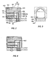
- FIG. 1 is an exploded, partially cutaway, perspective view of an electrical connector according to an embodiment of the invention;
- FIG. 2 is a sectional view of the electrical connector mounted on a printed circuit board;
- FIG. 3 is a rear view of the electrical connector; and
- FIG. 4 is a sectional view of an electrical connector according to another embodiment of the invention.
- In FIG. 1, the electrical connector 1 includes an
insulating housing 100, ablock member 200,contact elements 300, an endface protection member 400, acylindrical shield member 500, and ametal hood member 600. - The
insulating housing 100 is molded from an insulating material, such as a plastic, so as to have anannular recess 130 between acylindrical contact support 120 and ahousing body 110. Thehousing body 110 consists of acubic front section 111 and a U-shapedrear section 112. Fourengaging grooves 114 are provided on thefront surface 113 of thefront section 111 corresponding to theengaging lugs 501 of thecylindrical shield member 500. A pair oflatch slots 115 are provided on the upper corners of thefront surface 113 to receivelatch lances 402 of the endface protection member 400. A pair of T-shaped latch slots 116 are provided on the lower corners of thefront surface 113 to receivelatch lances 403 with a U-shapedcontact 404 extending therefrom. The T-shaped latch slots 116 communicate withattachment slots 140 extending forward from the rear end so that thecontacts 404 of the endface protection member 400 are connected electrically and mechanically to thecontact portions 621 of themetal hood member 600. - The
insulating housing 100 has aU-shaped recess 118 extending forward from therear end 117 for receiving the rear portion of thehood member 600. Thisrecess 118 communicates with a latch groove (not shown) into whichprojections 613 are pushed to secure thehood member 600 to theinsulation housing 100. Arear cavity 119 is provided on the lower portion of therear section 112 to receive theblock member 200. - A number of
contact apertures 121 are provided in thecontact support 120 for supporting thecontact sections 301 ofcontact elements 300. A pair ofelongated indentations 122 are provided on the circumferential surface of thecontact support 120 to receive theelongated contacts 610 of thehood member 600. These indentations communicate with the U-shapedrecess 118. Theannular recess 130 extends rearwardly from the front surface to receive thecylindrical shield member 500 and the shell member of a mating connector (not shown). - The
block member 200 is molded from a dielectric material, such as a plastic, so as to havelateral channels 201 for receiving intermediate sections 302 of thecontact elements 300 and avertical apertures 202 forreceiving connection sections 303 extending downwardly from the intermediate sections 302. Steppedlower edges 204 of theblock member 200 engagelower flanges 625 of thehood member 600. - As best shown in FIG. 2, each
contact 300 is made by stamping and forming a spring conductive metal sheet so as to have thefront contact section 301 for contact with the contact of a mating connector and therear connection section 304 consisting of the intermediate section 302 extending rearwardly from the front contact section and theterminal section 303 extending downwardly from the intermediate section. - The end
face protection member 400 is made by stamping and forming a thick metal plate so as to have acircular opening 401 at the center to receive the shell member of a mating connector. It has a square shape substantially identical with thefront surface 113 of theinsulating housing 100. A pair oflatch lances 402 and a pair oflatch lances 403 with a U-shapedcontact 404 extend rearwardly from the upper and lower portions of the endface protection member 400, respectively. - The
cylindrical shield member 500 is made by stamping and forming a spring metal thin sheet. Fourengaging lugs 501 extend outwardly from the front edge of theshield member 500 in radial directions and rest in thecutout seat 114 on the front end of theinsulating housing 100. A plurality ofcantilever contacts 502, which extend forwardly and inwardly, are provided on the circumferential surface of theshield member 500. - Like the
shield member 500, thehood member 600 is made by stamping and forming a spring metal thin sheet to have a pair ofelongated contacts 610 and a pair ofattachment sections 620. Theelongated contact 610 has a slightly inwardly bentfree end 611 for shield contact with the metal shield (not shown) provided on the inside of a mating shell member. An opening 612 is provided behind thefree end 612 to enhance the spring property of theelongated contact 610. Aprojection 613 is provided at the inside edge of the rear portion ofelongated contact 610 to prevent the metal hood member from falling off from the insulating housing. - The
attachment section 620 and theelongated contact 610 are integrated with alink section 630. A pair oflatch lances 631 extend forwardly from the front edge of thelink section 630 to be pushed into latch slots (not shown) of theinsulating housing 100. Acontact portion 621 extends forwardly from theattachment section 620 to be inserted into theattachment slot 140 of theinsulating housing 100 for contact with thecontact 404 of the endface protection member 500. Aprojection 622 is provided on the lower edge of thecontact portion 621 to prevent the contact portion from falling off from theattachment slot 140. - A
leg member 624 extends downwardly from theattachment section 620 to be inserted into a mounting slot of the printedcircuit board 20 and has aprojection 624 to engage the mounting slot. Thisleg member 623 is secured withsolder 30 to the ground circuit of a printedcircuit board 20. A pair offlanges 625 extend inwardly from the lower edges of theattachment section 620 to engage with the steppedlower edges 204 of theblock member 200 for support. - The electrical connector is assembled as follows.
- (1) The
contact portions 301 of L-shaped contacts 300 are inserted into therespective contact holes 121 on therear section 112 of theinsulating housing 100, while thecylindrical shield member 500 is inserted into theannular recess 130 on thefront section 111 of theinsulating housing 100. - (2) The end
face protection member 400 is then attached by pushing thelatch lances respective latch slots block member 200 is fitted into the lowerrear cavity 119 of therear housing section 112 such that theterminal portions 303 of thecontact elements 300 pass through thevertical apertures 202 and the intermediate portions 302 are fitted into thelateral channels 201. - (3) The
metal hood member 600 is then joined to theinsulating housing 100 so that theblock member 200 is supported by theflanges 625 of the metal hood member 600 (FIG. 3). - (4) the electrical connector is then mounted on the printed
circuit board 20 so that theterminal portions 303 ofcontacts 300 and theleg members 623 of thehood member 600 are soldered to the respective signal and ground circuits provided on the back of theboard 20. - FIG. 4 shows an electrical connector according to another embodiment of the invention. The
metal hood member 600 has aback plate 640 to enhance the shield effect. The other portions are the same as those of the hood member described above. - The terminal portions of L-shaped contacts are protected by the block member so that adherence to the contacts of dust and dirt is prevented whereby poor insulation and short circuit are prevented. An impact by an external object is blocked whereby deformation of the terminal portions is prevented. The metal hood encloses the terminal portions and enhances the electromagnetic interference protection. Moreover, repeated plugging in an out of a mating connector applies no or little load to the soldered joint so that there is little danger that the solder comes off from the board.
Claims (5)
said contact elements have a contact portion for contact with a mating contact element within said insulating housing, an intermediate portion extending rearwardly from said contact portion, and a terminal portion extending downwardly from said intermediate portion through said insulating housing;
said insulating housing has an annular recess for receiving a mating shell member, a rear cavity for receiving a block member for supporting said intermediate portions of contact elements within said hood member;
said hood member has a pair of leg members to be connected to a ground circuit on a printed circuit board and a pair of flanges extending inwardly from lower edges thereof for supporting said block member; and that
said block member has lateral channels for receiving said intermediate portions of contact elements and vertical apertures through which said terminal portions of contact elements are pass.
a block member having a plurality of lateral channels for receiving said intermediate portions and a plurality of vertical apertures for receiving said terminal portions, said block member being fitted into said rear cavity so that said intermediate and terminal portions are fitted into said lateral channels and said vertical apertures respectively.
Applications Claiming Priority (2)
| Application Number | Priority Date | Filing Date | Title |
|---|---|---|---|
| JP129622/88 | 1988-10-04 | ||
| JP1988129622U JPH0250983U (en) | 1988-10-04 | 1988-10-04 |
Publications (3)
| Publication Number | Publication Date |
|---|---|
| EP0371218A2 true EP0371218A2 (en) | 1990-06-06 |
| EP0371218A3 EP0371218A3 (en) | 1990-11-14 |
| EP0371218B1 EP0371218B1 (en) | 1995-03-01 |
Family
ID=15014031
Family Applications (1)
| Application Number | Title | Priority Date | Filing Date |
|---|---|---|---|
| EP89117148A Expired - Lifetime EP0371218B1 (en) | 1988-10-04 | 1989-09-15 | Electrical connector |
Country Status (4)
| Country | Link |
|---|---|
| US (1) | US4983127A (en) |
| EP (1) | EP0371218B1 (en) |
| JP (1) | JPH0250983U (en) |
| DE (1) | DE68921430T2 (en) |
Cited By (3)
| Publication number | Priority date | Publication date | Assignee | Title |
|---|---|---|---|---|
| EP0477856A2 (en) * | 1990-09-27 | 1992-04-01 | Hosiden Corporation | Socket and connector comprising a socket and a mating plug |
| EP0511897A1 (en) * | 1991-04-30 | 1992-11-04 | Itt Composants Et Instruments | Element of a shielded electrical connector |
| EP0997983A2 (en) * | 1998-10-21 | 2000-05-03 | Hirose Electric Co., Ltd. | Shield connector |
Families Citing this family (46)
| Publication number | Priority date | Publication date | Assignee | Title |
|---|---|---|---|---|
| JPH0637586Y2 (en) * | 1989-11-29 | 1994-09-28 | ホシデン株式会社 | Multi-pole connector socket |
| US5087210A (en) * | 1991-06-21 | 1992-02-11 | Amp Incorporated | Wire-to-wire electrical connecting means |
| JPH0521110A (en) * | 1991-07-10 | 1993-01-29 | Amp Japan Ltd | Shielding type electric connector |
| US5288248A (en) * | 1991-10-28 | 1994-02-22 | Foxconn International | Totally shielded DIN connector |
| FR2684810B1 (en) * | 1991-12-10 | 1994-03-18 | Souriau Cie | FORCE PLUGGABLE CONNECTOR ON A PRINTED BOARD. |
| US5228872A (en) * | 1992-05-05 | 1993-07-20 | Dan-Chief Enterprise Co., Ltd. | Shielded IDC type modular jack adapter |
| US5531606A (en) * | 1993-02-04 | 1996-07-02 | Thomas & Betts Corporation | Shielded vertically aligned electrical connector components |
| US5593311A (en) * | 1993-07-14 | 1997-01-14 | Thomas & Betts Corporation | Shielded compact data connector |
| DE4331143C1 (en) * | 1993-09-14 | 1995-02-02 | Gaertner Karl Telegaertner | Connecting socket for forming a connecting device for a data network |
| HUT68195A (en) * | 1993-09-14 | 1995-05-29 | Gaertner Karl Telegaertner | Connecting box and connecting cable for forming connecting device for a data network |
| US5564949A (en) * | 1995-01-05 | 1996-10-15 | Thomas & Betts Corporation | Shielded compact data connector |
| US5807120A (en) * | 1996-03-06 | 1998-09-15 | Elcon Products International | Printed circuit board power distribution connector |
| US5788538A (en) * | 1996-07-31 | 1998-08-04 | Berg Technology, Inc. | Shield for modular jack |
| TW310893U (en) * | 1996-11-22 | 1997-07-11 | Hon Hai Prec Ind Co Ltd | Socket for electric connector |
| US5913698A (en) * | 1997-05-01 | 1999-06-22 | Hon Hai Precision Ind. Co., Ltd. | Shielded connector |
| US6595801B1 (en) * | 1997-05-30 | 2003-07-22 | Molex Incorporated | Electrical connector with electrically isolated ESD and EMI shields |
| JP3675134B2 (en) * | 1997-10-21 | 2005-07-27 | 矢崎総業株式会社 | Shield connector |
| USD412489S (en) * | 1998-04-16 | 1999-08-03 | Elcon Products International | Electrical connector housing |
| USD408361S (en) * | 1998-04-24 | 1999-04-20 | Elcon Products International Company | Electrical connector housing |
| USD410894S (en) * | 1998-04-24 | 1999-06-15 | Elcon Products International Company | Electrical connector housing |
| USD416862S (en) * | 1998-08-07 | 1999-11-23 | Hon Hai Precision Ind. Co., Ltd. | Electrical connector |
| USD430109S (en) * | 1998-09-08 | 2000-08-29 | Hosiden Corporation | Electrical connector |
| JP2001006771A (en) * | 1999-06-18 | 2001-01-12 | Nec Corp | Connector |
| US6254402B1 (en) | 1999-06-23 | 2001-07-03 | Amphenol Corporation | Push pin ground |
| US6461174B1 (en) * | 2001-09-12 | 2002-10-08 | Hon Hai Precision Ind. Co., Ltd. | Power connector more easily and cheaply manufactured |
| JP3948397B2 (en) * | 2002-12-11 | 2007-07-25 | 日本航空電子工業株式会社 | connector |
| JP4474235B2 (en) * | 2004-08-11 | 2010-06-02 | 日本圧着端子製造株式会社 | connector |
| US7503807B2 (en) * | 2005-08-09 | 2009-03-17 | Tyco Electronics Corporation | Electrical connector adapter and method for making |
| US7452218B2 (en) * | 2006-03-21 | 2008-11-18 | Finisar Corporation | Grounding clip for grounding a printed circuit board in a transceiver module |
| CN101192723B (en) * | 2006-11-24 | 2010-06-02 | 富士康(昆山)电脑接插件有限公司 | Electric connector |
| US20100041257A1 (en) * | 2008-08-14 | 2010-02-18 | Tyco Electronics Corporation | Emi shielded electrical connector |
| TWM399523U (en) * | 2010-09-06 | 2011-03-01 | Jye Tai Prec Ind Co Ltd | Improved high power socket connector |
| JP5884135B2 (en) * | 2012-01-25 | 2016-03-15 | 矢崎総業株式会社 | Connector unit |
| US8944850B2 (en) * | 2012-10-22 | 2015-02-03 | Apple Inc. | Shielding for edge connector |
| CN204243363U (en) * | 2014-02-21 | 2015-04-01 | 番禺得意精密电子工业有限公司 | Electric connector |
| US9484654B2 (en) * | 2014-04-10 | 2016-11-01 | Foxconn Interconnect Technology Limited | Electrical connector with improved contacts |
| CN106231848A (en) * | 2016-08-26 | 2016-12-14 | 新乡市光明电器有限公司 | Main power source control assembly |
| US9905953B1 (en) | 2016-09-30 | 2018-02-27 | Slobodan Pavlovic | High power spring-actuated electrical connector |
| US9966713B1 (en) * | 2017-01-18 | 2018-05-08 | R&S Shaeffer Properties LLC | Receptacle assemblies |
| US10027072B1 (en) | 2017-01-18 | 2018-07-17 | R&S Schaeffer Properties LLC | Plug assemblies |
| US10177483B1 (en) * | 2018-02-06 | 2019-01-08 | Te Connectivity Corporation | Electrical connector assembly with impedance control at mating interface |
| CH716093B1 (en) | 2018-02-26 | 2023-12-29 | Royal Prec Products Llc | Spring actuated electrical connector for heavy duty applications. |
| WO2019237009A1 (en) | 2018-06-07 | 2019-12-12 | Royal Precision Products, Llc | Electrical connector system with internal spring component |
| US11721942B2 (en) | 2019-09-09 | 2023-08-08 | Eaton Intelligent Power Limited | Connector system for a component in a power management system in a motor vehicle |
| CN114787815A (en) | 2019-09-09 | 2022-07-22 | 伊顿智能动力有限公司 | Connector recording system with readable and recordable indicia |
| KR20230043171A (en) | 2020-07-29 | 2023-03-30 | 이턴 인텔리전트 파워 리미티드 | Connector system with interlock system |
Citations (3)
| Publication number | Priority date | Publication date | Assignee | Title |
|---|---|---|---|---|
| EP0118168A1 (en) * | 1983-01-31 | 1984-09-12 | AMP INCORPORATED (a New Jersey corporation) | Electrical plug connector and receptacle therefor |
| US4486059A (en) * | 1982-09-20 | 1984-12-04 | Magnetic Controls Company | Receptacle assembly |
| US4637669A (en) * | 1985-06-07 | 1987-01-20 | Hosiden Electronics Co., Ltd. | Connector socket |
Family Cites Families (3)
| Publication number | Priority date | Publication date | Assignee | Title |
|---|---|---|---|---|
| JPS5823191B2 (en) * | 1974-04-22 | 1983-05-13 | 松下電工株式会社 | Setsutenosetsusouchi |
| JPS61184285A (en) * | 1985-02-08 | 1986-08-16 | Sumitomo Electric Ind Ltd | Anti-freezing valve |
| US4722691A (en) * | 1986-02-03 | 1988-02-02 | General Motors Corporation | Header assembly for a printed circuit board |
-
1988
- 1988-10-04 JP JP1988129622U patent/JPH0250983U/ja active Pending
-
1989
- 1989-09-15 US US07/407,626 patent/US4983127A/en not_active Expired - Fee Related
- 1989-09-15 EP EP89117148A patent/EP0371218B1/en not_active Expired - Lifetime
- 1989-09-15 DE DE68921430T patent/DE68921430T2/en not_active Expired - Fee Related
Patent Citations (3)
| Publication number | Priority date | Publication date | Assignee | Title |
|---|---|---|---|---|
| US4486059A (en) * | 1982-09-20 | 1984-12-04 | Magnetic Controls Company | Receptacle assembly |
| EP0118168A1 (en) * | 1983-01-31 | 1984-09-12 | AMP INCORPORATED (a New Jersey corporation) | Electrical plug connector and receptacle therefor |
| US4637669A (en) * | 1985-06-07 | 1987-01-20 | Hosiden Electronics Co., Ltd. | Connector socket |
Cited By (8)
| Publication number | Priority date | Publication date | Assignee | Title |
|---|---|---|---|---|
| EP0477856A2 (en) * | 1990-09-27 | 1992-04-01 | Hosiden Corporation | Socket and connector comprising a socket and a mating plug |
| EP0477856A3 (en) * | 1990-09-27 | 1993-04-21 | Hosiden Corporation | Socket |
| EP0511897A1 (en) * | 1991-04-30 | 1992-11-04 | Itt Composants Et Instruments | Element of a shielded electrical connector |
| FR2676146A1 (en) * | 1991-04-30 | 1992-11-06 | Itt Composants Instr | SHIELDED ELECTRICAL CONNECTOR ELEMENT. |
| US5209677A (en) * | 1991-04-30 | 1993-05-11 | Itt Composants Et Instruments | Shielded electrical connector element |
| EP0997983A2 (en) * | 1998-10-21 | 2000-05-03 | Hirose Electric Co., Ltd. | Shield connector |
| EP0997983A3 (en) * | 1998-10-21 | 2000-09-27 | Hirose Electric Co., Ltd. | Shield connector |
| US6234840B1 (en) | 1998-10-21 | 2001-05-22 | Hirose Electric Co., Ltd. | Shield connector |
Also Published As
| Publication number | Publication date |
|---|---|
| US4983127A (en) | 1991-01-08 |
| EP0371218A3 (en) | 1990-11-14 |
| EP0371218B1 (en) | 1995-03-01 |
| DE68921430T2 (en) | 1995-10-26 |
| JPH0250983U (en) | 1990-04-10 |
| DE68921430D1 (en) | 1995-04-06 |
Similar Documents
| Publication | Publication Date | Title |
|---|---|---|
| US4983127A (en) | Electrical connector | |
| EP0584838B1 (en) | Electrical connector | |
| EP1610421B1 (en) | Connector in which reliable ground connection is assured | |
| EP0188876B1 (en) | Shielded electrical connector assembly | |
| JP3142837U (en) | Plug connector with mating protection | |
| US6165017A (en) | Cable end connector | |
| EP0292144B1 (en) | Electrical connector | |
| US6086421A (en) | Electrical connector with one-piece shield | |
| US7086901B2 (en) | Shielded electrical connector | |
| EP0675573A2 (en) | Card edge connector with combined shielding and voltage drain protection | |
| US6241556B1 (en) | Retention member for connector | |
| EP0893854A2 (en) | Shielded electrical connector | |
| WO1988008627A1 (en) | Electrical connector shielded member having mounting means | |
| EP0362601B1 (en) | Electrical connector | |
| US5611711A (en) | Electrical connector assembly | |
| US5466175A (en) | Shield connector connecting shield cables | |
| US4906208A (en) | Electrical connector | |
| US20060121781A1 (en) | Electrical connector having a shielding shell | |
| EP0362599B1 (en) | Mounting structure for electrical connector | |
| EP0308490B1 (en) | Electrical connector shielded member having mounting means | |
| US6264504B1 (en) | Electrical connector | |
| WO1998013906A1 (en) | Combined ground strap and board lock for electrical connector assembly | |
| US6554642B1 (en) | Electrical connector | |
| US20050042923A1 (en) | Shielded electrical connector | |
| WO1999026321A1 (en) | Shielded electrical connector |
Legal Events
| Date | Code | Title | Description |
|---|---|---|---|
| PUAI | Public reference made under article 153(3) epc to a published international application that has entered the european phase |
Free format text: ORIGINAL CODE: 0009012 |
|
| AK | Designated contracting states |
Kind code of ref document: A2 Designated state(s): AT BE CH DE ES FR GB GR IT LI LU NL SE |
|
| PUAL | Search report despatched |
Free format text: ORIGINAL CODE: 0009013 |
|
| AK | Designated contracting states |
Kind code of ref document: A3 Designated state(s): AT BE CH DE ES FR GB GR IT LI LU NL SE |
|
| 17P | Request for examination filed |
Effective date: 19901228 |
|
| RBV | Designated contracting states (corrected) |
Designated state(s): DE GB |
|
| 17Q | First examination report despatched |
Effective date: 19930402 |
|
| GRAA | (expected) grant |
Free format text: ORIGINAL CODE: 0009210 |
|
| AK | Designated contracting states |
Kind code of ref document: B1 Designated state(s): DE GB |
|
| REF | Corresponds to: |
Ref document number: 68921430 Country of ref document: DE Date of ref document: 19950406 |
|
| PLBE | No opposition filed within time limit |
Free format text: ORIGINAL CODE: 0009261 |
|
| STAA | Information on the status of an ep patent application or granted ep patent |
Free format text: STATUS: NO OPPOSITION FILED WITHIN TIME LIMIT |
|
| 26N | No opposition filed | ||
| PGFP | Annual fee paid to national office [announced via postgrant information from national office to epo] |
Ref country code: GB Payment date: 20000913 Year of fee payment: 12 |
|
| PGFP | Annual fee paid to national office [announced via postgrant information from national office to epo] |
Ref country code: DE Payment date: 20000929 Year of fee payment: 12 |
|
| PG25 | Lapsed in a contracting state [announced via postgrant information from national office to epo] |
Ref country code: GB Free format text: LAPSE BECAUSE OF NON-PAYMENT OF DUE FEES Effective date: 20010915 |
|
| REG | Reference to a national code |
Ref country code: GB Ref legal event code: IF02 |
|
| PG25 | Lapsed in a contracting state [announced via postgrant information from national office to epo] |
Ref country code: DE Free format text: LAPSE BECAUSE OF NON-PAYMENT OF DUE FEES Effective date: 20020501 |
|
| GBPC | Gb: european patent ceased through non-payment of renewal fee |
Effective date: 20010915 |