EP0375673A2 - An infusion apparatus - Google Patents
An infusion apparatus Download PDFInfo
- Publication number
- EP0375673A2 EP0375673A2 EP90301328A EP90301328A EP0375673A2 EP 0375673 A2 EP0375673 A2 EP 0375673A2 EP 90301328 A EP90301328 A EP 90301328A EP 90301328 A EP90301328 A EP 90301328A EP 0375673 A2 EP0375673 A2 EP 0375673A2
- Authority
- EP
- European Patent Office
- Prior art keywords
- housing
- diaphragm
- pressure
- liquid
- passage
- Prior art date
- Legal status (The legal status is an assumption and is not a legal conclusion. Google has not performed a legal analysis and makes no representation as to the accuracy of the status listed.)
- Ceased
Links
Images
Classifications
-
- A—HUMAN NECESSITIES
- A61—MEDICAL OR VETERINARY SCIENCE; HYGIENE
- A61M—DEVICES FOR INTRODUCING MEDIA INTO, OR ONTO, THE BODY; DEVICES FOR TRANSDUCING BODY MEDIA OR FOR TAKING MEDIA FROM THE BODY; DEVICES FOR PRODUCING OR ENDING SLEEP OR STUPOR
- A61M5/00—Devices for bringing media into the body in a subcutaneous, intra-vascular or intramuscular way; Accessories therefor, e.g. filling or cleaning devices, arm-rests
- A61M5/14—Infusion devices, e.g. infusing by gravity; Blood infusion; Accessories therefor
- A61M5/168—Means for controlling media flow to the body or for metering media to the body, e.g. drip meters, counters ; Monitoring media flow to the body
- A61M5/16831—Monitoring, detecting, signalling or eliminating infusion flow anomalies
- A61M5/16854—Monitoring, detecting, signalling or eliminating infusion flow anomalies by monitoring line pressure
-
- Y—GENERAL TAGGING OF NEW TECHNOLOGICAL DEVELOPMENTS; GENERAL TAGGING OF CROSS-SECTIONAL TECHNOLOGIES SPANNING OVER SEVERAL SECTIONS OF THE IPC; TECHNICAL SUBJECTS COVERED BY FORMER USPC CROSS-REFERENCE ART COLLECTIONS [XRACs] AND DIGESTS
- Y10—TECHNICAL SUBJECTS COVERED BY FORMER USPC
- Y10S—TECHNICAL SUBJECTS COVERED BY FORMER USPC CROSS-REFERENCE ART COLLECTIONS [XRACs] AND DIGESTS
- Y10S128/00—Surgery
- Y10S128/13—Infusion monitoring
Definitions
- This invention relates to apparatus for the infusion of medical liquids into patients and is particularly concerned with infusion sets which are used with infusion pumps and pressure monitors. Frequently it is required that particular medical liquids be infused into the body of a patient at a predetermined rate. It is possible for the tube of an infusion set leading to the patient to be kinked, or get blocked, and, under these circumstances, firstly the medical liquid is no longer infused into the patient which is the first source of danger but, perhaps more importantly, if the tube is subsequently unkinked or the blockage suddenly released a large quantity of the medical liquid is suddenly infused into the patient as a result of the build up of pressure in the kinked or blocked tube. Such a sudden surge of medical liquid into the patient can be life threatening, particularly in the case of some drugs.
- infusion pressure monitor which monitors the pressure of the medical fluid in an infusion set or tube leading to the patient.
- infusion pressure monitoring devices have included a pressure sensor and means to compare the sensed pressure with a preset value corresponding to the maximum allowed delivery pressure.
- the delivery pressure for an infusion varies with a number of factors such as the viscosity of the medical fluid, the cross sectional area of the needle through which the infusion is performed, the speed at which the infusion of medical fluid is to be introduced into the patient and whether a filter is included in the infusion line.
- Infusion pressure monitoring devices are also available in which an operator sets manually the required maximum delivery pressure. Naturally such devices are subject to human error and, even more importantly, there is a tendency for the operator to set the maximum infusion pressure to a high value so that the operator is not troubled by "false alarms".
- the parent European EP-A-0195637 describes and claims an infusion pump pressure monitor comprising means to drive an infusion pump, a pressure sensor to monitor the delivery pressure downstream of the pump, and a programmed computer programmed to monitor the maximum output of the sensor and hence the maximum delivery pressure that occurs during an initial operating period, and then, subsequently to monitor the output of the sensor and hence the delivery pressure downstream of the pump for the remainder of the delivery period of the infusion pump, the programmed computer being programmed to disable the means to drive the infusion pump if the monitored delivery pressure differs by more than a predetermined amount from the maximum pressure monitored during the initial operating period.
- a liquid infusion set for use in infusing a medical liquid into a patient includes a pressure responsive chamber to enable the infusion pressure of the medical liquid to be monitored during infusion by an associated pressure sensor, the pressure responsive chamber comprising a substantially rigid, hollow housing having a flanged end face, and a resilient flexible diaphragm connected to the flange and covering the end face, the housing also having a liquid inlet and a liquid outlet passage in communication with the inside of the housing and hence in communication with an inside face of the diaphragm, the liquid inlet and outlet passage being mutually orthogonal with one of them extending substantially normally away from the diaphragm, in use, the flanged end of the housing co-operating with a keyhole-shaped slot in the pressure sensor to associate the diaphragm with a sensing element, and the said one of the inlet and outlet passage providing at least part of finger gripping means to enable the pressure responsive chamber to
- the flanged end of the housing is circular and the flange forms the outer extremity of a dished face.
- the housing preferably also includes a hollow box-like portion opening into the dished face and extending in a direction away from the diaphragm.
- the inlet passage opens into one end of the hollow box-like portion and the outlet passage opens into the other end of the hollow box-like portion remote from the diaphragm.
- a circular skirt is connected to the external surface of the dished face and extends away from the diaphragm.
- the skirt preferably forms an integral part of the end faces of the rectangular box-like portion and additional reinforcing webs may be provided extending between the inside of the skirt and the sides of the rectangular box-like section.
- the finger-gripping means also includes an additional web extending between the said one of the inlet and outlet passage and the rear face of the box-like portion of the housing, the web being generally rectangular in shape.
- This web firstly buttresses the connection between the said one of the inlet and outlet passage and the remainder of the housing and also provides a convenient tab to be held by an operator when inserting the pressure responsive chamber into the pressure sensor.
- the generally rectangular web is formed with a serpentine or ribbed configuration so that it can be gripped more easily.
- the infusion set also includes tubing connecting the inlet passage to a Luer-lock connector so that it can be associated with the outlet of a conventional infusion syringe.
- the infusion set preferably further includes microbore tubing connecting the outlet passage to a Luer-lock connector for attachment to an infusion needle assembly.
- the infusion set may also include an additive Y site through which additional medical liquid can be injected into the infusion set and may include a filter.
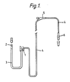
- a disposable infusion set includes a pressure responsive chamber 1 which is connected to a Luer-lock connector 2 by inlet tubing 3.
- the pressure responsive chamber 1 is connected via kink resistant small bore tubing 4 to an additive Y-site 5 and thence to a Luer-lock connector 6 which, in use, is connected to an infusion needle assembly inserted in a patient.
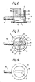
- the pressure responsive chamber 1 comprises a substantially rigid circular housing 10 with an annular bevelled edge flange 11 at one end.
- a resilient thin flexible diaphragm 12 is welded onto the flange and extends across the end face of the housing 10.
- the inside of the housing is dished to provide a chamber of small volume between the diaphragm 12 and the dished face 13.
- the housing also includes a generally rectangular box-like portion 14 showing most clearly in Figures 3 and 4 which communicates with the dished shaped face 13 via an oval opening 15.
- An inlet passage 16 communicates with one end of the box-like portion 14 and an outlet passage 17 communicates with the other end of the box-like portion 14.
- the outlet passage 17 and inlet passage 16 are mutually orthogonal with the outlet passage 17 being substantially normal to the diaphragm 12.
- a generally rectangular finger-gripping tab 18 extends between the outlet passage 17 and the base of the rectangular box-like portion 14.
- the surface of the tab 18 includes a number of ribs 19 so that it is easier to grip, in use.
- An additional rib 20 is provided at the side of the outlet passage 17 remote from the tab 18 to further extend the finger-gripping tab.
- a circular skirt 21 surrounds and extends rearwards away from the flanged end 11 to stiffen the housing.
- This skirt 21 is attached via reinforcing webs 22 and 23 to the box-like portion 14.
- the stiffening webs 22 and 23 include extensions 24 and 25 which buttress the rectangular finger-gripping portion 18 and provide further means for engagement between the fingers of the user and the chamber.
- the pressure responsive chamber has a very low volume and this, together with the small bore tubing 4 leads to a very low priming volume for the entire infusion set.
- the arrangement of the inlet and outlet tube, together with the web 18 provides a strong robust and substantially rigid housing which can be easily gripped and manoeuvred by an operator into its associated pressure monitor in use.
- a typical pressure monitor with which the infusion set is used forms part of an infusion driver which holds a syringe filled with medical liquid and actuates the plunger of the syringe to discharge the medical liquid from the syringe through the infusion set and into the patient.
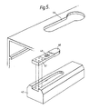
- a pressure sensing element 38 of it comprises a load surface 40 located at the free end of a cantilevered aluminium beam 41, the other end of which is fixed to a support block 42.
- the cantilevered beam 41 includes a bending portion having a reduced thickness with a pair of strain gauges 43 bonded on opposite sides of it.
- a case for the pressure monitor includes a keyhole-shaped slot 44 located above the pressure sensor, and the flange 11 of the pressure responsive chamber of the infusion set is introduced into the enlarged end of the keyhole-shaped slot 44 and then moved along the parallel-sided portion so that the flange 11 is retained by the sides of the keyhole-shaped slot 44.
- the flexible diaphragm 12 engages the load surface 40 of the beam 41 so that pressure of liquid inside the chamber 1 bears against the free end of the aluminium beam 41 and causes a bending of the beam 41 corresponding to the pressure of the liquid inside the chamber 1.
- the two strain gauges 43 are connected together in a bridge circuit which is in turn connected across the input of a differential operational amplifier.
Abstract
Description
- This invention relates to apparatus for the infusion of medical liquids into patients and is particularly concerned with infusion sets which are used with infusion pumps and pressure monitors. Frequently it is required that particular medical liquids be infused into the body of a patient at a predetermined rate. It is possible for the tube of an infusion set leading to the patient to be kinked, or get blocked, and, under these circumstances, firstly the medical liquid is no longer infused into the patient which is the first source of danger but, perhaps more importantly, if the tube is subsequently unkinked or the blockage suddenly released a large quantity of the medical liquid is suddenly infused into the patient as a result of the build up of pressure in the kinked or blocked tube. Such a sudden surge of medical liquid into the patient can be life threatening, particularly in the case of some drugs.
- It is therefore desirable to provide some form of automatic infusion pressure monitor which monitors the pressure of the medical fluid in an infusion set or tube leading to the patient. Previously such infusion pressure monitoring devices have included a pressure sensor and means to compare the sensed pressure with a preset value corresponding to the maximum allowed delivery pressure. The delivery pressure for an infusion varies with a number of factors such as the viscosity of the medical fluid, the cross sectional area of the needle through which the infusion is performed, the speed at which the infusion of medical fluid is to be introduced into the patient and whether a filter is included in the infusion line. Conventional infusion pressure monitoring devices which include a preset maximum pressure limit typically have their maximum pressure limit set to a value higher than is likely to be encountered with, for example, a high viscosity medical liquid being pumped at a high rate through a filter and fine needle. When such a device is subsequently used with less viscous medical liquids at lower pumping rates through coarser needles the monitoring device is relatively insensitive and so only responds if the infusion tube is completely blocked for a considerable period of time.
- Infusion pressure monitoring devices are also available in which an operator sets manually the required maximum delivery pressure. Naturally such devices are subject to human error and, even more importantly, there is a tendency for the operator to set the maximum infusion pressure to a high value so that the operator is not troubled by "false alarms".
- The parent European EP-A-0195637 describes and claims an infusion pump pressure monitor comprising means to drive an infusion pump, a pressure sensor to monitor the delivery pressure downstream of the pump, and a programmed computer programmed to monitor the maximum output of the sensor and hence the maximum delivery pressure that occurs during an initial operating period, and then, subsequently to monitor the output of the sensor and hence the delivery pressure downstream of the pump for the remainder of the delivery period of the infusion pump, the programmed computer being programmed to disable the means to drive the infusion pump if the monitored delivery pressure differs by more than a predetermined amount from the maximum pressure monitored during the initial operating period.
- The present invention provides an infusion set for use with such infusion pump pressure monitors and according to this invention a liquid infusion set for use in infusing a medical liquid into a patient includes a pressure responsive chamber to enable the infusion pressure of the medical liquid to be monitored during infusion by an associated pressure sensor, the pressure responsive chamber comprising a substantially rigid, hollow housing having a flanged end face, and a resilient flexible diaphragm connected to the flange and covering the end face, the housing also having a liquid inlet and a liquid outlet passage in communication with the inside of the housing and hence in communication with an inside face of the diaphragm, the liquid inlet and outlet passage being mutually orthogonal with one of them extending substantially normally away from the diaphragm, in use, the flanged end of the housing co-operating with a keyhole-shaped slot in the pressure sensor to associate the diaphragm with a sensing element, and the said one of the inlet and outlet passage providing at least part of finger gripping means to enable the pressure responsive chamber to be manoeuvred into the keyhole-shaped slot of the pressure sensor.
- Preferably the flanged end of the housing is circular and the flange forms the outer extremity of a dished face. In this case the housing preferably also includes a hollow box-like portion opening into the dished face and extending in a direction away from the diaphragm. The inlet passage opens into one end of the hollow box-like portion and the outlet passage opens into the other end of the hollow box-like portion remote from the diaphragm.
- Preferably a circular skirt is connected to the external surface of the dished face and extends away from the diaphragm. The skirt preferably forms an integral part of the end faces of the rectangular box-like portion and additional reinforcing webs may be provided extending between the inside of the skirt and the sides of the rectangular box-like section.
- Preferably the finger-gripping means also includes an additional web extending between the said one of the inlet and outlet passage and the rear face of the box-like portion of the housing, the web being generally rectangular in shape. This web firstly buttresses the connection between the said one of the inlet and outlet passage and the remainder of the housing and also provides a convenient tab to be held by an operator when inserting the pressure responsive chamber into the pressure sensor. Preferably the generally rectangular web is formed with a serpentine or ribbed configuration so that it can be gripped more easily.
- Preferably the infusion set also includes tubing connecting the inlet passage to a Luer-lock connector so that it can be associated with the outlet of a conventional infusion syringe. The infusion set preferably further includes microbore tubing connecting the outlet passage to a Luer-lock connector for attachment to an infusion needle assembly. The infusion set may also include an additive Y site through which additional medical liquid can be injected into the infusion set and may include a filter.
- A particular example of an infusion set in accordance with this invention will now be described with reference to the accompanying drawings in which:-
- Figure 1 is a diagram of an infusion set;
- Figure 2 is a partly sectioned side elevation of the pressure responsive chamber;
- Figure 3 is a plan of the pressure responsive chamber;
- Figure 4 is an underplan of the pressure responsive chamber; and,
- Figure 5 is an exploded perspective view of part of the pressure sensor with which the set is used.
- In this example a disposable infusion set includes a pressure responsive chamber 1 which is connected to a Luer-
lock connector 2 byinlet tubing 3. The pressure responsive chamber 1 is connected via kink resistant small bore tubing 4 to an additive Y-site 5 and thence to a Luer-lock connector 6 which, in use, is connected to an infusion needle assembly inserted in a patient. - The pressure responsive chamber 1 comprises a substantially rigid
circular housing 10 with an annular bevellededge flange 11 at one end. A resilient thinflexible diaphragm 12 is welded onto the flange and extends across the end face of thehousing 10. The inside of the housing is dished to provide a chamber of small volume between thediaphragm 12 and thedished face 13. The housing also includes a generally rectangular box-like portion 14 showing most clearly in Figures 3 and 4 which communicates with the dished shapedface 13 via anoval opening 15. - An
inlet passage 16 communicates with one end of the box-like portion 14 and anoutlet passage 17 communicates with the other end of the box-like portion 14. Theoutlet passage 17 andinlet passage 16 are mutually orthogonal with theoutlet passage 17 being substantially normal to thediaphragm 12. A generally rectangular finger-gripping tab 18 extends between theoutlet passage 17 and the base of the rectangular box-like portion 14. The surface of thetab 18 includes a number ofribs 19 so that it is easier to grip, in use. Anadditional rib 20 is provided at the side of theoutlet passage 17 remote from thetab 18 to further extend the finger-gripping tab. - A
circular skirt 21 surrounds and extends rearwards away from theflanged end 11 to stiffen the housing. Thisskirt 21 is attached via reinforcingwebs like portion 14. Thestiffening webs extensions portion 18 and provide further means for engagement between the fingers of the user and the chamber. The pressure responsive chamber has a very low volume and this, together with the small bore tubing 4 leads to a very low priming volume for the entire infusion set. The arrangement of the inlet and outlet tube, together with theweb 18 provides a strong robust and substantially rigid housing which can be easily gripped and manoeuvred by an operator into its associated pressure monitor in use. - A typical pressure monitor with which the infusion set is used forms part of an infusion driver which holds a syringe filled with medical liquid and actuates the plunger of the syringe to discharge the medical liquid from the syringe through the infusion set and into the patient. A pressure sensing element 38 of it comprises a
load surface 40 located at the free end of a cantileveredaluminium beam 41, the other end of which is fixed to asupport block 42. The cantileveredbeam 41 includes a bending portion having a reduced thickness with a pair ofstrain gauges 43 bonded on opposite sides of it. A case for the pressure monitor includes a keyhole-shaped slot 44 located above the pressure sensor, and theflange 11 of the pressure responsive chamber of the infusion set is introduced into the enlarged end of the keyhole-shaped slot 44 and then moved along the parallel-sided portion so that theflange 11 is retained by the sides of the keyhole-shaped slot 44. In this position, theflexible diaphragm 12 engages theload surface 40 of thebeam 41 so that pressure of liquid inside the chamber 1 bears against the free end of thealuminium beam 41 and causes a bending of thebeam 41 corresponding to the pressure of the liquid inside the chamber 1. The twostrain gauges 43 are connected together in a bridge circuit which is in turn connected across the input of a differential operational amplifier. A complete description of the pressure monitor is given in EP-A-0195637.
Claims (3)
Applications Claiming Priority (4)
| Application Number | Priority Date | Filing Date | Title |
|---|---|---|---|
| GB8507210 | 1985-03-20 | ||
| GB858507210A GB8507210D0 (en) | 1985-03-20 | 1985-03-20 | Infusion pump pressure monitor |
| GB8511036 | 1985-05-01 | ||
| GB858511036A GB8511036D0 (en) | 1985-05-01 | 1985-05-01 | Liquid infusion set |
Related Parent Applications (2)
| Application Number | Title | Priority Date | Filing Date |
|---|---|---|---|
| EP86301941.0 Division | 1986-03-17 | ||
| EP86301941A Division EP0195637A3 (en) | 1985-03-20 | 1986-03-17 | An infusion apparatus |
Publications (2)
| Publication Number | Publication Date |
|---|---|
| EP0375673A2 true EP0375673A2 (en) | 1990-06-27 |
| EP0375673A3 EP0375673A3 (en) | 1990-08-01 |
Family
ID=26289001
Family Applications (2)
| Application Number | Title | Priority Date | Filing Date |
|---|---|---|---|
| EP86301941A Ceased EP0195637A3 (en) | 1985-03-20 | 1986-03-17 | An infusion apparatus |
| EP90301328A Ceased EP0375673A3 (en) | 1985-03-20 | 1986-03-17 | An infusion apparatus |
Family Applications Before (1)
| Application Number | Title | Priority Date | Filing Date |
|---|---|---|---|
| EP86301941A Ceased EP0195637A3 (en) | 1985-03-20 | 1986-03-17 | An infusion apparatus |
Country Status (3)
| Country | Link |
|---|---|
| US (1) | US4752289A (en) |
| EP (2) | EP0195637A3 (en) |
| CA (1) | CA1270712A (en) |
Cited By (1)
| Publication number | Priority date | Publication date | Assignee | Title |
|---|---|---|---|---|
| WO2000041747A1 (en) * | 1999-01-13 | 2000-07-20 | Ulrich Gmbh & Co. Kg | Injector for applying fluids fitted with a pressure measuring system |
Families Citing this family (28)
| Publication number | Priority date | Publication date | Assignee | Title |
|---|---|---|---|---|
| CA1283827C (en) * | 1986-12-18 | 1991-05-07 | Giorgio Cirelli | Appliance for injection of liquid formulations |
| US4950244A (en) * | 1987-05-01 | 1990-08-21 | Abbott Laboratories | Pressure sensor assembly for disposable pump cassette |
| US5201711A (en) * | 1987-09-30 | 1993-04-13 | Sherwood Medical Company | Safety interlock system for medical fluid pumps |
| US4863425A (en) * | 1987-12-04 | 1989-09-05 | Pacesetter Infusion, Ltd. | Patient-side occlusion detection system for a medication infusion system |
| US4943279A (en) * | 1988-09-30 | 1990-07-24 | C. R. Bard, Inc. | Medical pump with infusion controlled by a detachable coded label |
| US5000664A (en) * | 1989-06-07 | 1991-03-19 | Abbott Laboratories | Apparatus and method to test for valve leakage in a pump assembly |
| US5010473A (en) * | 1989-08-31 | 1991-04-23 | Duke University | Method and apparatus for model-based control of an open-loop process |
| US5053747A (en) * | 1989-09-05 | 1991-10-01 | Pacesetter Infusion, Inc. | Ultrasonic air-in-line detector self-test technique |
| CA2137772A1 (en) * | 1992-06-09 | 1993-12-23 | Shan Padda | Programmable infusion pump with interchangeable tubing |
| US5232439A (en) * | 1992-11-02 | 1993-08-03 | Infusion Technologies Corporation | Method for pumping fluid from a flexible, variable geometry reservoir |
| US5609575A (en) * | 1994-04-11 | 1997-03-11 | Graseby Medical Limited | Infusion pump and method with dose-rate calculation |
| US5637093A (en) * | 1995-03-06 | 1997-06-10 | Sabratek Corporation | Infusion pump with selective backlight |
| US5620312A (en) * | 1995-03-06 | 1997-04-15 | Sabratek Corporation | Infusion pump with dual-latching mechanism |
| US5628619A (en) * | 1995-03-06 | 1997-05-13 | Sabratek Corporation | Infusion pump having power-saving modes |
| US5904668A (en) * | 1995-03-06 | 1999-05-18 | Sabratek Corporation | Cassette for an infusion pump |
| US5795327A (en) * | 1995-03-06 | 1998-08-18 | Sabratek Corporation | Infusion pump with historical data recording |
| US6044852A (en) * | 1996-09-10 | 2000-04-04 | Landa, Inc. | Parts washer |
| US6468242B1 (en) | 1998-03-06 | 2002-10-22 | Baxter International Inc. | Medical apparatus with patient data recording |
| US20070213660A1 (en) * | 2004-10-29 | 2007-09-13 | Mark Richards | Fibrin sealant delivery device including pressure monitoring, and method and kits thereof |
| GR20050100452A (en) | 2005-09-02 | 2007-04-25 | Estelle Enterprises Limited | Fluid exchange catheter's system |
| US8012120B2 (en) | 2007-09-13 | 2011-09-06 | Avant Medical Corp. | Device and method for the automatic initiation of an injection |
| DE102007049446A1 (en) | 2007-10-16 | 2009-04-23 | Cequr Aps | Catheter introducer |
| US8547239B2 (en) | 2009-08-18 | 2013-10-01 | Cequr Sa | Methods for detecting failure states in a medicine delivery device |
| US8672873B2 (en) | 2009-08-18 | 2014-03-18 | Cequr Sa | Medicine delivery device having detachable pressure sensing unit |
| US9211378B2 (en) | 2010-10-22 | 2015-12-15 | Cequr Sa | Methods and systems for dosing a medicament |
| GB201305758D0 (en) * | 2013-03-28 | 2013-05-15 | Quanta Fluid Solutions Ltd | Blood Pump |
| CN110170089A (en) * | 2019-06-28 | 2019-08-27 | 广州市便携医疗科技有限公司 | A kind of perfusion tube pressure sensor |
| DE102020207084A1 (en) | 2020-06-05 | 2021-12-09 | B. Braun Melsungen Aktiengesellschaft | Infusion filter |
Citations (4)
| Publication number | Priority date | Publication date | Assignee | Title |
|---|---|---|---|---|
| US4126132A (en) * | 1975-07-28 | 1978-11-21 | Andros Incorporated | Intravenous and intra arterial delivery system |
| US4263808A (en) * | 1979-03-26 | 1981-04-28 | Baxter Travenol Laboratories, Inc. | Noninvasive pressure monitor |
| US4277227A (en) * | 1979-07-02 | 1981-07-07 | Imed Corporation | Apparatus for converting a pump to a controller |
| WO1982001997A1 (en) * | 1980-12-15 | 1982-06-24 | Corp Ivac | Pressure diaphragm |
Family Cites Families (10)
| Publication number | Priority date | Publication date | Assignee | Title |
|---|---|---|---|---|
| NO125760B (en) * | 1971-02-17 | 1972-10-30 | Sentralinst For Ind Forskning | |
| DE2608381C2 (en) * | 1976-03-01 | 1978-03-30 | Hottinger Baldwin Messtechnik Gmbh, 6100 Darmstadt | Transmitter |
| US4148314A (en) * | 1976-10-18 | 1979-04-10 | Baxter Travenol Laboratories, Inc. | Blood pressure alarm system for dialysis machines |
| US4184491A (en) * | 1977-08-31 | 1980-01-22 | The United States Of America As Represented By The Administrator Of The National Aeronautics And Space Administration | Intra-ocular pressure normalization technique and equipment |
| US4326519A (en) * | 1980-02-21 | 1982-04-27 | Abbott Laboratories | Venipuncture device |
| DE3018641C2 (en) * | 1980-05-16 | 1986-05-28 | Hans 8228 Freilassing Rodler | Automatic infusion pump |
| US4394862A (en) * | 1980-08-25 | 1983-07-26 | Baxter Travenol Laboratories, Inc. | Metering apparatus with downline pressure monitoring system |
| US4392849A (en) * | 1981-07-27 | 1983-07-12 | The Cleveland Clinic Foundation | Infusion pump controller |
| US4460355A (en) * | 1982-06-11 | 1984-07-17 | Ivac Corporation | Fluid pressure monitoring system |
| US4526574A (en) * | 1983-05-23 | 1985-07-02 | Baxter Travenol Laboratories, Inc. | Differential occlusion sensing method and apparatus |
-
1986
- 1986-03-17 EP EP86301941A patent/EP0195637A3/en not_active Ceased
- 1986-03-17 EP EP90301328A patent/EP0375673A3/en not_active Ceased
- 1986-03-17 US US06/840,387 patent/US4752289A/en not_active Expired - Fee Related
- 1986-03-20 CA CA000504651A patent/CA1270712A/en not_active Expired - Fee Related
Patent Citations (4)
| Publication number | Priority date | Publication date | Assignee | Title |
|---|---|---|---|---|
| US4126132A (en) * | 1975-07-28 | 1978-11-21 | Andros Incorporated | Intravenous and intra arterial delivery system |
| US4263808A (en) * | 1979-03-26 | 1981-04-28 | Baxter Travenol Laboratories, Inc. | Noninvasive pressure monitor |
| US4277227A (en) * | 1979-07-02 | 1981-07-07 | Imed Corporation | Apparatus for converting a pump to a controller |
| WO1982001997A1 (en) * | 1980-12-15 | 1982-06-24 | Corp Ivac | Pressure diaphragm |
Cited By (1)
| Publication number | Priority date | Publication date | Assignee | Title |
|---|---|---|---|---|
| WO2000041747A1 (en) * | 1999-01-13 | 2000-07-20 | Ulrich Gmbh & Co. Kg | Injector for applying fluids fitted with a pressure measuring system |
Also Published As
| Publication number | Publication date |
|---|---|
| EP0195637A2 (en) | 1986-09-24 |
| US4752289A (en) | 1988-06-21 |
| EP0195637A3 (en) | 1987-08-19 |
| EP0375673A3 (en) | 1990-08-01 |
| CA1270712A (en) | 1990-06-26 |
Similar Documents
| Publication | Publication Date | Title |
|---|---|---|
| EP0375673A2 (en) | An infusion apparatus | |
| EP1225936B1 (en) | Positive pressure infusion system having downstream resistance measurement capability | |
| US5190522A (en) | Device for monitoring the operation of a delivery system and the method of use thereof | |
| EP0058167B1 (en) | Metering apparatus with downline pressure monitoring system | |
| US5423746A (en) | Method and apparatus for infiltration detection during administration of intravenous fluids | |
| US5688244A (en) | Apparatus for monitoring infusion | |
| US4743228A (en) | Fluid flow monitoring method and system | |
| US5382232A (en) | Infusion system with air-in-line clear function | |
| US8535280B2 (en) | Pressure based refill status monitor for implantable pumps | |
| EP1699509B1 (en) | Empty container detection using container side pressure sensing | |
| CA2087809C (en) | Fluid line condition detection | |
| EP1706160B1 (en) | Medication safety enhancement for secondary infusion | |
| US5419770A (en) | Self priming tubing set for an infusion device | |
| US6149631A (en) | Drip impinging intravenous drip chamber | |
| US5098409A (en) | Intravenous bag and monitoring method | |
| US8016790B2 (en) | Infusion status indicator | |
| EP2327430A1 (en) | Infusion pump system | |
| EP2352535B1 (en) | Alarm identification system for infusion set when installed in pump assembly | |
| US20180117241A1 (en) | Systems and methods for improved air-in-line detection for infusion pumps | |
| EP0592483A1 (en) | Apparatus for patient-controlled infusion. | |
| EP0874659A1 (en) | Infusion pump with disposable tubing and size indicating means | |
| EP2620173A1 (en) | Intravenous infusion pump system | |
| JPH08173530A (en) | Blood conduit,wound secretion liquid conduit or safety device for transfusion liquid conduit | |
| US20130310770A1 (en) | Infusion Apparatus With Composition Pulse Flow Sensor | |
| US4785821A (en) | Pressure monitor and regulating device for administration of medicament |
Legal Events
| Date | Code | Title | Description |
|---|---|---|---|
| PUAI | Public reference made under article 153(3) epc to a published international application that has entered the european phase |
Free format text: ORIGINAL CODE: 0009012 |
|
| PUAL | Search report despatched |
Free format text: ORIGINAL CODE: 0009013 |
|
| 17P | Request for examination filed |
Effective date: 19900302 |
|
| AC | Divisional application: reference to earlier application |
Ref document number: 195637 Country of ref document: EP |
|
| AK | Designated contracting states |
Kind code of ref document: A2 Designated state(s): CH DE FR GB LI NL SE |
|
| RIN1 | Information on inventor provided before grant (corrected) |
Inventor name: ROSSO, VINCENT ANTHONY Inventor name: FRAMPTON, PAUL FREDERICK Inventor name: CARTER, NIGEL FAWBERT Inventor name: BALDING, ALAN STUART |
|
| AK | Designated contracting states |
Kind code of ref document: A3 Designated state(s): CH DE FR GB LI NL SE |
|
| RAP1 | Party data changed (applicant data changed or rights of an application transferred) |
Owner name: KNIGHT, ROBERT LEONARD HARRY |
|
| 17Q | First examination report despatched |
Effective date: 19911024 |
|
| STAA | Information on the status of an ep patent application or granted ep patent |
Free format text: STATUS: THE APPLICATION HAS BEEN REFUSED |
|
| 18R | Application refused |
Effective date: 19920412 |