EP0377141A2 - Pipe control and closure device - Google Patents
Pipe control and closure device Download PDFInfo
- Publication number
- EP0377141A2 EP0377141A2 EP89122980A EP89122980A EP0377141A2 EP 0377141 A2 EP0377141 A2 EP 0377141A2 EP 89122980 A EP89122980 A EP 89122980A EP 89122980 A EP89122980 A EP 89122980A EP 0377141 A2 EP0377141 A2 EP 0377141A2
- Authority
- EP
- European Patent Office
- Prior art keywords
- shut
- pressure chambers
- axial direction
- pipe
- another
- Prior art date
- Legal status (The legal status is an assumption and is not a legal conclusion. Google has not performed a legal analysis and makes no representation as to the accuracy of the status listed.)
- Withdrawn
Links
Images
Classifications
-
- G—PHYSICS
- G01—MEASURING; TESTING
- G01M—TESTING STATIC OR DYNAMIC BALANCE OF MACHINES OR STRUCTURES; TESTING OF STRUCTURES OR APPARATUS, NOT OTHERWISE PROVIDED FOR
- G01M3/00—Investigating fluid-tightness of structures
- G01M3/02—Investigating fluid-tightness of structures by using fluid or vacuum
- G01M3/26—Investigating fluid-tightness of structures by using fluid or vacuum by measuring rate of loss or gain of fluid, e.g. by pressure-responsive devices, by flow detectors
- G01M3/28—Investigating fluid-tightness of structures by using fluid or vacuum by measuring rate of loss or gain of fluid, e.g. by pressure-responsive devices, by flow detectors for pipes, cables or tubes; for pipe joints or seals; for valves ; for welds
- G01M3/2838—Investigating fluid-tightness of structures by using fluid or vacuum by measuring rate of loss or gain of fluid, e.g. by pressure-responsive devices, by flow detectors for pipes, cables or tubes; for pipe joints or seals; for valves ; for welds for cables
-
- F—MECHANICAL ENGINEERING; LIGHTING; HEATING; WEAPONS; BLASTING
- F16—ENGINEERING ELEMENTS AND UNITS; GENERAL MEASURES FOR PRODUCING AND MAINTAINING EFFECTIVE FUNCTIONING OF MACHINES OR INSTALLATIONS; THERMAL INSULATION IN GENERAL
- F16L—PIPES; JOINTS OR FITTINGS FOR PIPES; SUPPORTS FOR PIPES, CABLES OR PROTECTIVE TUBING; MEANS FOR THERMAL INSULATION IN GENERAL
- F16L55/00—Devices or appurtenances for use in, or in connection with, pipes or pipe systems
- F16L55/10—Means for stopping flow from or in pipes or hoses
- F16L55/12—Means for stopping flow from or in pipes or hoses by introducing into the pipe a member expandable in situ
- F16L55/128—Means for stopping flow from or in pipes or hoses by introducing into the pipe a member expandable in situ introduced axially into the pipe or hose
- F16L55/1283—Plugging pig
-
- F—MECHANICAL ENGINEERING; LIGHTING; HEATING; WEAPONS; BLASTING
- F16—ENGINEERING ELEMENTS AND UNITS; GENERAL MEASURES FOR PRODUCING AND MAINTAINING EFFECTIVE FUNCTIONING OF MACHINES OR INSTALLATIONS; THERMAL INSULATION IN GENERAL
- F16L—PIPES; JOINTS OR FITTINGS FOR PIPES; SUPPORTS FOR PIPES, CABLES OR PROTECTIVE TUBING; MEANS FOR THERMAL INSULATION IN GENERAL
- F16L55/00—Devices or appurtenances for use in, or in connection with, pipes or pipe systems
- F16L55/10—Means for stopping flow from or in pipes or hoses
- F16L55/12—Means for stopping flow from or in pipes or hoses by introducing into the pipe a member expandable in situ
- F16L55/128—Means for stopping flow from or in pipes or hoses by introducing into the pipe a member expandable in situ introduced axially into the pipe or hose
- F16L55/132—Means for stopping flow from or in pipes or hoses by introducing into the pipe a member expandable in situ introduced axially into the pipe or hose the closure device being a plug fixed by radially deforming the packing
- F16L55/134—Means for stopping flow from or in pipes or hoses by introducing into the pipe a member expandable in situ introduced axially into the pipe or hose the closure device being a plug fixed by radially deforming the packing by means of an inflatable packing
-
- G—PHYSICS
- G01—MEASURING; TESTING
- G01M—TESTING STATIC OR DYNAMIC BALANCE OF MACHINES OR STRUCTURES; TESTING OF STRUCTURES OR APPARATUS, NOT OTHERWISE PROVIDED FOR
- G01M3/00—Investigating fluid-tightness of structures
- G01M3/02—Investigating fluid-tightness of structures by using fluid or vacuum
- G01M3/26—Investigating fluid-tightness of structures by using fluid or vacuum by measuring rate of loss or gain of fluid, e.g. by pressure-responsive devices, by flow detectors
- G01M3/28—Investigating fluid-tightness of structures by using fluid or vacuum by measuring rate of loss or gain of fluid, e.g. by pressure-responsive devices, by flow detectors for pipes, cables or tubes; for pipe joints or seals; for valves ; for welds
- G01M3/2853—Investigating fluid-tightness of structures by using fluid or vacuum by measuring rate of loss or gain of fluid, e.g. by pressure-responsive devices, by flow detectors for pipes, cables or tubes; for pipe joints or seals; for valves ; for welds for pipe joints or seals
Definitions
- the invention relates to a pipe test and shut-off device with a fixed tubular cylindrical inner part and two annular pressure chambers arranged at a distance from one another in the axial direction, the radial outer surfaces of which can bear on a pipe to be tested or blocked when pressurized.
- Pipe test and shut-off devices of this type are used for a variety of purposes, in particular for section-by-section leak tests of socket seals, since the tightness of the pipes supplied has already been checked by the manufacturer for newly installed pipes, so that leaks often only occur in the socket seals.
- a device of the type described above contains two circumferential channels connected by a metal cylinder and spaced apart from one another in the axial direction, in which are located tubular pressure bodies which can be pressurized.
- Devices of this type require in every application that when testing Pipe leaks by supplying pressure from the outside a fluid pressure must be built up in the space between the two tubular pressure bodies, so that time is lost and additional equipment is required.
- the device is assigned to a given diameter of the pipe to be tested and / or shut off only with a small tolerance, so that several devices with different diameters must be kept ready. The possibility of adapting to tolerances of the diameter and the roundness of the pipe to be tested and / or blocked is small.
- the invention aims to provide a pipe test and shut-off device, in which the disadvantages described do not occur, and which ensures a high level of operational safety, particularly when used economically, and can be adapted to a wide range of pipe diameters.
- a pipe testing and shut-off device of the type mentioned in which the two pressure chambers are connected to one another on the inside by at least one position which is essentially tensile in the axial direction and are freely movable in the axial direction in such a way that their inner side walls are at Increasing the pressurization approach each other.
- the essentially tensile layer consists of rubberized cord fabric, the warp threads of which are arranged in the axial direction.
- Another essential feature is that the centers of the inwardly facing surfaces of the annular pressure chambers are above the ends of the substantially tensile layer.
- a further preferred feature is that there is a further layer of rubberized cord fabric, the warp threads of which are arranged in the axial direction, above the essentially tensile layer, which lies against the inner side walls of the pressure chambers.
- warp threads of the pressure chambers run in the circumferential direction, so that their side parts can expand laterally when the pressure is increased.
- these can be constructed in multiple layers, the warp threads of the individual layers alternately forming acute angles with one another.
- the two pressure chambers have one or more through openings in the part connecting them.
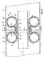
- FIG. 1 shows an outer tube 1, the socket connection 2 of which is sealed with respect to the next outer tube 4 by means of a seal 3.
- the task is to test the socket connection 2 for leaks.
- the pipe test and shut-off device 5 is arranged according to the invention at the connection point 6 of the two outer pipes 1 and 4.
- the device 5 contains an inner cylinder 7 made of metal or plastic, which is essentially dimensionally stable.
- the weft threads are either thin and elastic or not available. The axially parallel position of the warp threads ensures a high tensile strength of the layer 8 in the direction of the axis 9.
- annular pressure chambers 10 and 11 On the inner cylinder 7 there are annular pressure chambers 10 and 11, the radial outer surfaces 12 and 13 of which lie sealingly on the inner surfaces of the tubes 1 and 4 when they are pressurized.
- the pressure chambers 10 and 11 are designed and arranged such that their radially inwardly facing surfaces 14 and 15 are arranged approximately symmetrically to the ends of the layer 8, so that these surfaces 14 and 15 each rest approximately half on the layer 8.
- layer 8 there is another layer 8a made of rubberized cord fabric, which lies against the inner side walls 19 and 20 of the pressure chambers 10 and 11 and whose warp threads are arranged in the axial direction 9.
- a transverse layer 17 is placed around the layer 8a, the warp threads of which extend in the circumferential direction, so that radially outward forces can be absorbed.
- An outer layer 22 is placed around the arrangement thus formed.
- the pressure chambers can be constructed in multiple layers if higher pressures are to be absorbed by them.
- the warp threads of the individual layers can alternately form acute angles to the transverse axis or with one another.
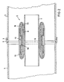
- Fig. 2 shows the embodiment shown in Fig. 1 with pressure relief.
- the device 5 then has a significantly smaller volume than when pressurized during operation.
- the particular advantage of the pipe test and shut-off device described lies primarily in the fact that it can be adapted to a wide variety of applications. In this way, even pipes that have certain tolerances with regard to the dimensions and the accuracy of the circular shape of their inner diameter can be reliably sealed.
- the design also has the advantage that, in certain cases, the provision of special pressure sources for the space enclosed by the pressure chambers can be dispensed with.
- the two pressure chambers can be pressurized separately or together. When acting together, it may be advantageous to connect the two pressure chambers to one another permanently or in a lockable manner, e.g. by a connection in the part connecting the two pressure chambers.
- the device can advantageously be adapted to other operational requirements. Connections, valves, etc. for compressed air, pressurized water, etc. to the pressure chambers 10 and 11 and for the space 16 enclosed by them can be present in the inner cylinder.
- the device can then be used like a device with only one pressure chamber for sealing, bypassing, testing and shutting off pipelines.
Abstract
Description
Die Erfindung bezieht sich auf ein Rohrprüf- und -absperrgerät mit einem festen rohrzylindrischen Innenteil und zwei in achsialer Richtung im Abstand voneinander angeordneten ringförmigen Druckkammern, deren radiale Außenflächen bei Druckbeaufschlagung an einem zu prüfenden oder abzusperrenden Rohr anliegen können.The invention relates to a pipe test and shut-off device with a fixed tubular cylindrical inner part and two annular pressure chambers arranged at a distance from one another in the axial direction, the radial outer surfaces of which can bear on a pipe to be tested or blocked when pressurized.
Rohrprüf- und -absperrgeräte dieser Art werden für vielfältige Zwecke benutzt, insbesondere für abschnittsweise Dichtheitsprüfungen von Muffendichtungen, da bei neu verlegten Rohrleitungen die Dichtheit der gelieferten Rohre bereits vom Hersteller geprüft wurde, so daß vielfach nur noch bei den Muffendichtungen Undichtigkeiten auftreten.Pipe test and shut-off devices of this type are used for a variety of purposes, in particular for section-by-section leak tests of socket seals, since the tightness of the pipes supplied has already been checked by the manufacturer for newly installed pipes, so that leaks often only occur in the socket seals.
Weitere Anwendungsmöglichkeiten sind Dichtheitsprüfungen vollständiger Rohrleitungen und Schächte, und im Katastropheneinsatz das kurzfristige vollständige Absperren von Entwässerungsleitungen und -schächten. Allgemein kommt auch das Absperren von Rohren bei Kanalreinigungsarbeiten, bei Kanal-Videountersuchungen, bei Rohr- und Schachtsanierungen, bei Kanalbelüftungen und Entgasungen, bei Kontrollen und Begehungen und beim Bau von Rohrleitungen in Betracht.Other possible uses include leak testing of entire pipelines and manholes and, in the event of a disaster, the short-term complete shut-off of drainage pipes and ducts. In general, the shutdown of pipes is also considered for sewer cleaning work, sewer video surveys, pipe and shaft renovation, sewer ventilation and degassing, inspections and inspections and the construction of pipelines.
Ein Gerät der vorstehend beschriebenen Art enthält zwei durch einen Metallzylinder verbundene, in Achsrichtung im Abstand voneinander gehaltene Umfangsrinnen, in denen sich mit Druck beaufschlagbare schlauchförmige Druckkörper befinden. Geräte dieser Art erfordern in jedem Anwendungsfall, daß bei der Prüfung von Rohrundichtigkeiten durch Druckzufuhr von außen ein Fluiddruck in dem Raum zwischen den beiden schlauchförmigen Druckkörpern aufgebaut werden muß, so daß Zeitverluste eintreten und zusätzliche Ausrüstung erforderlich ist. Auch ist das Gerät nur mit geringer Toleranz einem vorgegebenen Durchmesser des zu prüfenden und/oder abzusperrenden Rohres zugeordnet, so daß mehrere Geräte mit verschiedenen Durchmessern bereitgehalten werden müssen. Dabei ist die Möglichkeit der Anpassung an Toleranzen des Durchmessers und der Rundheit des zu prüfenden und/oder abzusperrenden Rohres gering.A device of the type described above contains two circumferential channels connected by a metal cylinder and spaced apart from one another in the axial direction, in which are located tubular pressure bodies which can be pressurized. Devices of this type require in every application that when testing Pipe leaks by supplying pressure from the outside a fluid pressure must be built up in the space between the two tubular pressure bodies, so that time is lost and additional equipment is required. Also, the device is assigned to a given diameter of the pipe to be tested and / or shut off only with a small tolerance, so that several devices with different diameters must be kept ready. The possibility of adapting to tolerances of the diameter and the roundness of the pipe to be tested and / or blocked is small.
Diese Nachteile ließen sich teilweise dadurch beheben, daß zwei einzelne Sperrkörper, die größeren Durchmessertoleranzen anpaßbar sind, in Achsrichtung miteinander verbunden werden, z.B. durch ein Seil oder eine Kette. Dies bedingt jedoch einen hohen Flächendruck abhängig von dem Durchmesser des Rohres, so daß bei großen Durchmessern erhebliche Zugkräfte auftreten, die zum Bruch oder zur Dehnung der Zugverbindung führen können. Auch besteht der Nachteil, daß die beiden Sperrkörper separat unter Fluiddruck gesetzt werden oder aber durch einen Schlauch miteinander verbunden werden müssen, so daß weitere Komplikationen eintreten.These disadvantages could be partially remedied by connecting two individual locking bodies, which are adaptable to larger diameter tolerances, in the axial direction, e.g. through a rope or a chain. However, this requires a high surface pressure depending on the diameter of the tube, so that considerable tensile forces occur at large diameters, which can lead to breakage or expansion of the train connection. There is also the disadvantage that the two blocking bodies are placed separately under fluid pressure or else have to be connected to one another by a hose, so that further complications arise.
Die Erfindung bezweckt, ein Rohrprüf- und -absperrgerät zu schaffen, bei dem die beschriebenen Nachteile nicht auftreten, und das insbesondere bei wirtschaftlichem Einsatz eine hohe Betriebssicherheit gewährleistet und einem weiten Bereich von Rohrdurchmessern angepaßt werden kann.The invention aims to provide a pipe test and shut-off device, in which the disadvantages described do not occur, and which ensures a high level of operational safety, particularly when used economically, and can be adapted to a wide range of pipe diameters.
Gemäß der Erfindung ist ein Rohrprüf- und -absperrgerät der eingangs bezeichneten Art vorgesehen, bei dem die beiden Druckkammern an der Innenseite durch wenigstens eine in Achsrichtung im wesentlichen zugfeste Lage miteinander verbunden sind und in Achsrichtung derart frei bewegbar sind, daß sich ihre inneren Seitenwandungen bei Erhöhung der Druckbeaufschlagung einander nähern.According to the invention, a pipe testing and shut-off device of the type mentioned is provided, in which the two pressure chambers are connected to one another on the inside by at least one position which is essentially tensile in the axial direction and are freely movable in the axial direction in such a way that their inner side walls are at Increasing the pressurization approach each other.
Gemäß einer bevorzugten Ausführungsform ist vorgesehen, daß die im wesenlichen zugfeste Lage aus gummiertem Cordgewebe besteht, deren Kettfäden in Achsrichtung angeordnet sind.According to a preferred embodiment it is provided that the essentially tensile layer consists of rubberized cord fabric, the warp threads of which are arranged in the axial direction.
Ein weiteres wesentliches Merkmal ist, daß sich die Mitten der nach innen gerichteten Flächen der ringförmigen Druckkammern über den Enden der im wesentlichen zugfesten Lage befinden.Another essential feature is that the centers of the inwardly facing surfaces of the annular pressure chambers are above the ends of the substantially tensile layer.
Ein weiteres bevorzugtes Merkmal ist, daß sich über der im wesentlichen zugfesten Lage eine weitere, an den inneren Seitenwandungen der Druckkammern anliegende Lage aus gummiertem Cordgewebe befindet, deren Kettfäden in Achsrichtung angeordnet sind.A further preferred feature is that there is a further layer of rubberized cord fabric, the warp threads of which are arranged in the axial direction, above the essentially tensile layer, which lies against the inner side walls of the pressure chambers.
Auch werden Vorteile erreicht, wenn sich auf der in Achsrichtung im wesentlichen zugfesten weiteren Lage eine Querlage befindet, deren Kettfäden in Umfangsrichtung verlaufen, derart, daß radial nach außen wirkende Kräfte aufgenommen werden können.Advantages are also achieved if there is a transverse layer on the further layer which is essentially tensile in the axial direction, the warp threads of which extend in the circumferential direction, such that forces which act radially outward can be absorbed.
Eine weitere bevorzugte Ausführungsform besteht darin, daß die Kettfäden der Druckkammern in Umfangsrichtung verlaufen, so daß ihre Seitenteile bei Druckerhöhung sich seitlich ausdehnen können.Another preferred embodiment is that the warp threads of the pressure chambers run in the circumferential direction, so that their side parts can expand laterally when the pressure is increased.
Wenn höhere Drücke von den Druckkammern aufgenommen werden müssen, können diese mehrlagig aufgebaut werden, wobei die Kettfäden der einzelnen Lagen abwechselnd spitze Winkel miteinander bilden.If higher pressures have to be absorbed by the pressure chambers, these can be constructed in multiple layers, the warp threads of the individual layers alternately forming acute angles with one another.
Auch ist es vorteilhaft, daß die beiden Druckkammern in dem sie verbindenden Teil eine oder mehrere Durchgangsöfffnungen haben.It is also advantageous that the two pressure chambers have one or more through openings in the part connecting them.
Die Erfindung wird nachfolgend anhand der Zeichnungen näher beschrieben.
- Fig. 1 zeigt ein Ausführungsbeispiel eines Rohrprüf- und -absperrgeräts im Längsschnitt in Betriebslage.
- Fig. 2 zeigt den Gegenstand der Fig. 1 bei Druckentlastung.
- Fig. 1 shows an embodiment of a pipe testing and shut-off device in longitudinal section in the operating position.
- Fig. 2 shows the subject of Fig. 1 with pressure relief.
Das in Fig. 1 dargestellte Ausführungsbeispiel zeigt ein Außenrohr 1, dessen Muffenverbindung 2 über eine Dichtung 3 gegenüber dem nächsten Außenrohr 4 abgedichtet ist. Es sei die Aufgabe gestellt, die Muffenverbindung 2 auf Dichtheit zu prüfen.The exemplary embodiment shown in FIG. 1 shows an
Zu diesem Zweck wird das Rohrprüf- und -absperrgerät 5 gemäß der Erfindung an der Verbindungsstelle 6 der beiden Außenrohre 1 und 4 angeordnet. Das Gerät 5 enthält einen Innenzylinder 7 aus Metall oder Kunststoff, der im wesentlichen formstabil ist. Auf dem Innenzylinder 7 befindet sich eine zylindrische Lage 8 aus gummiertem Cordgewebe, welche als Festigkeitsträger dient und so gelegt ist, daß die Kette des Gewebes in Richtung der Rohrachse 9 liegt. Die Schußfäden sind entweder dünn und elastisch oder nicht vorhanden. Durch die achsparallele Lage der Kettfäden ist eine hohe Zugfestigkeit der Lage 8 in Richtung der Achse 9 gewährleistet.For this purpose, the pipe test and shut-off
Auf dem Innenzylinder 7 befinden sich ringförmige Druckkammern 10 und 11, deren radiale Außenflächen 12 und 13 an den Innenflächen der Rohre 1 und 4 dichtend anliegen, wenn sie mit Druck beaufschlagt werden. Die Druckkammern 10 und 11 sind so ausgebildet und angeordnet, daß ihre radial nach innen gerichteten Flächen 14 und 15 etwa symmetrisch zu den Enden der Lage 8 angeordnet sind, so daß diese Flächen 14 und 15 etwa je zur Hälfte auf der Lage 8 aufliegen.On the
Über der Lage 8 befindet sich eine weitere Lage 8a aus gummiertem Cordgewebe, die an den inneren Seitenwandungen 19 und 20 der Druckkammern 10 und 11 anliegt, und deren Kettfäden in Achsrichtung 9 angeordnet sind.Above the
Als Sicherung gegen radial nach außem gerichtete Kräfte ist um die Lage 8a eine Querlage 17 gelegt, deren Kettfäden in Umfangstung verlaufen, so daß radial nach außen gerichtete Kräfte aufgenommen werden können. Um die so gebildete Anordnung ist eine äußere Schicht 22 gelegt.As a safeguard against radially outward forces, a
Da die Kettfäden des Cordmaterials der Druckkammern 10 und 11 auf zu der Achse 9 konzentrischen Kreisen liegen, ist bei Druckerhöhung eine kräftige Wölbung der Seitenteile 18, 19, 20 und 21 möglich. Dies hat die erwünschte Folge, daß das Volumen des Raumes 16 bei Erhöhung der Druckbeaufschlagung wesentlich verringert wird, so daß der Druck des im Raum 16 eingeschlossenen Mediums erhöht ist. Es ist dadurch in vielen Fällen möglich, z.B. bei der Prüfung der Dichtheit einer Muffenverbindung auf den Aufbau eines Druckes in dem Raum 16, z.B. durch Druckpumpen oder Druckbehälter, zu verzichten.Since the warp threads of the cord material of the
Wie bereits erwähnt, können die Druckkammern mehrlagig aufgebaut werden, wenn von ihnen höhere Drücke aufzunehmen sind. Die Kettfäden der einzelnen Lagen können dabei abwechselnd spitze Winkel zur Querachse bzw. miteinander bilden.As already mentioned, the pressure chambers can be constructed in multiple layers if higher pressures are to be absorbed by them. The warp threads of the individual layers can alternately form acute angles to the transverse axis or with one another.
Fig. 2 zeigt die in Fig. 1 dargestellte Ausführungsform bei Druckentlastung. Das Gerät 5 hat dann ein wesentlich kleineres Volumen als bei Druckbeaufschlagung im Betrieb.Fig. 2 shows the embodiment shown in Fig. 1 with pressure relief. The
Der besondere Vorteil des beschriebenen Rohrprüf- und -absperrgerätes liegt vor allem darin, daß es den vielfältigsten Anwendungsmöglichkeiten angepaßt werden kann. So können auch solche Rohre, die hinsichtlich der Abmessungen und der Exaktheit der Kreisform ihres Innendurchmessers gewisse Toleranzen aufweisen, zuverlässig abgedichtet werden. Auch ist durch die Bauart der vorteil gegeben, daß in bestimmten Fällen die Bereitstellung besonderer Druckquellen für den von den Druckkammern eingeschlossenen Raum entfallen kann.The particular advantage of the pipe test and shut-off device described lies primarily in the fact that it can be adapted to a wide variety of applications. In this way, even pipes that have certain tolerances with regard to the dimensions and the accuracy of the circular shape of their inner diameter can be reliably sealed. The design also has the advantage that, in certain cases, the provision of special pressure sources for the space enclosed by the pressure chambers can be dispensed with.
Die beiden Druckkammern können separat oder gemeinsam mit Druck beaufschlagt werden. Bei gemeinsamer Beaufschlagung kann es vorteilhaft sein, die beiden Druckkammern ständig oder absperrbar miteinander zu verbinden, z.B. durch eine Verbindung in dem die beiden Druckkammern verbindenden Teil.The two pressure chambers can be pressurized separately or together. When acting together, it may be advantageous to connect the two pressure chambers to one another permanently or in a lockable manner, e.g. by a connection in the part connecting the two pressure chambers.
Das Gerät kann in vorteilhafter Weise weiteren betrieblichen Erfordernissen angepaßt werden. So können im Innenzylinder Anschlüsse, Ventile usw. für Druckluft, Druckwasser usw. zu den Druckkammern 10 und 11 sowie für den von ihnen eingeschlossenen Raum 16 vorhanden sein.The device can advantageously be adapted to other operational requirements. Connections, valves, etc. for compressed air, pressurized water, etc. to the
Weitere Anwendungsmöglichkeiten ergeben sich, wenn der freie Durchfluß durch den Innenzylinder 7 ganz oder teilweise geschlossen wird. Das Gerät kann dann wie ein Gerät mit nur einer Druckkammer zur Abdichtung, zum Umleitung, zum Prüfen und zum Absperren von Rohrleitungen verwendet werden.Further possible applications result if the free flow through the
Claims (8)
Applications Claiming Priority (2)
| Application Number | Priority Date | Filing Date | Title |
|---|---|---|---|
| DE3900025 | 1989-01-02 | ||
| DE19893900025 DE3900025A1 (en) | 1989-01-02 | 1989-01-02 | PIPE TEST AND SHUT-OFF DEVICE |
Publications (2)
| Publication Number | Publication Date |
|---|---|
| EP0377141A2 true EP0377141A2 (en) | 1990-07-11 |
| EP0377141A3 EP0377141A3 (en) | 1990-12-19 |
Family
ID=6371518
Family Applications (1)
| Application Number | Title | Priority Date | Filing Date |
|---|---|---|---|
| EP19890122980 Withdrawn EP0377141A3 (en) | 1989-01-02 | 1989-12-13 | Pipe control and closure device |
Country Status (2)
| Country | Link |
|---|---|
| EP (1) | EP0377141A3 (en) |
| DE (1) | DE3900025A1 (en) |
Cited By (5)
| Publication number | Priority date | Publication date | Assignee | Title |
|---|---|---|---|---|
| DE4344736A1 (en) * | 1993-12-28 | 1995-06-29 | Uwe Schultz | Pneumatic regulator and blocking element in pipes, gutters |
| DE19717720A1 (en) * | 1997-04-18 | 1998-10-22 | Stein & Partner Gmbh Prof Dr I | Pipe inspection and maintenance device |
| WO2002021036A1 (en) * | 2000-09-05 | 2002-03-14 | Tyco Electronics Raychem Gmbh | Inflatable seal |
| FR3016952A1 (en) * | 2014-01-28 | 2015-07-31 | Gdf Suez | TOOL FOR INTERVENTION ON THE WALL OF A PIPELINE - ASSOCIATED METHOD. |
| ES2562716A1 (en) * | 2016-02-03 | 2016-03-07 | José Vicente MARQUÉS MUÑOZ | Fixing device for reservoir inflator tank sealed conduit shutter, and sealing assembly incorporating a reservoir provided with said fixation device (Machine-translation by Google Translate, not legally binding) |
Families Citing this family (3)
| Publication number | Priority date | Publication date | Assignee | Title |
|---|---|---|---|---|
| DE4315927C2 (en) * | 1993-05-12 | 1998-01-29 | Woellner Werke | Process for sealing and repairing damaged buried pipelines and existing systems, and device for carrying out the process |
| DE29714238U1 (en) * | 1997-08-08 | 1998-07-09 | Jt Elektronik Gmbh | Socket tester |
| CN104634524B (en) * | 2013-11-11 | 2017-06-09 | 富鼎电子科技(嘉善)有限公司 | Air-tightness detection device |
Citations (4)
| Publication number | Priority date | Publication date | Assignee | Title |
|---|---|---|---|---|
| GB212715A (en) * | 1923-02-10 | 1924-03-20 | Frederick Leonard Ball | Improvements in or relating to apparatus for testing pipe-joints for leakage |
| US3915197A (en) * | 1974-03-22 | 1975-10-28 | Theordore G Piccirilli | Collapsible packer apparatus for sealing pipe leaks |
| US3946761A (en) * | 1974-06-24 | 1976-03-30 | The Penetryn System, Inc. | Packer for sealing pipe leaks |
| US3985688A (en) * | 1972-05-18 | 1976-10-12 | Minnesota Mining And Manufacturing Company | Poly (urethane-urea) foam sealants for underground application and fluid precursors |
-
1989
- 1989-01-02 DE DE19893900025 patent/DE3900025A1/en not_active Withdrawn
- 1989-12-13 EP EP19890122980 patent/EP0377141A3/en not_active Withdrawn
Patent Citations (4)
| Publication number | Priority date | Publication date | Assignee | Title |
|---|---|---|---|---|
| GB212715A (en) * | 1923-02-10 | 1924-03-20 | Frederick Leonard Ball | Improvements in or relating to apparatus for testing pipe-joints for leakage |
| US3985688A (en) * | 1972-05-18 | 1976-10-12 | Minnesota Mining And Manufacturing Company | Poly (urethane-urea) foam sealants for underground application and fluid precursors |
| US3915197A (en) * | 1974-03-22 | 1975-10-28 | Theordore G Piccirilli | Collapsible packer apparatus for sealing pipe leaks |
| US3946761A (en) * | 1974-06-24 | 1976-03-30 | The Penetryn System, Inc. | Packer for sealing pipe leaks |
Cited By (9)
| Publication number | Priority date | Publication date | Assignee | Title |
|---|---|---|---|---|
| DE4344736A1 (en) * | 1993-12-28 | 1995-06-29 | Uwe Schultz | Pneumatic regulator and blocking element in pipes, gutters |
| DE19717720A1 (en) * | 1997-04-18 | 1998-10-22 | Stein & Partner Gmbh Prof Dr I | Pipe inspection and maintenance device |
| WO2002021036A1 (en) * | 2000-09-05 | 2002-03-14 | Tyco Electronics Raychem Gmbh | Inflatable seal |
| FR3016952A1 (en) * | 2014-01-28 | 2015-07-31 | Gdf Suez | TOOL FOR INTERVENTION ON THE WALL OF A PIPELINE - ASSOCIATED METHOD. |
| WO2015114243A1 (en) * | 2014-01-28 | 2015-08-06 | Gdf Suez | Tool for working on the wall of a pipe and related method |
| US10215323B2 (en) | 2014-01-28 | 2019-02-26 | Engie | Tool for working on the wall of a pipe and related method |
| US10605397B2 (en) | 2014-01-28 | 2020-03-31 | Engie | Tool for working on the wall of a pipe and related method |
| US10605396B2 (en) | 2014-01-28 | 2020-03-31 | Engie | Tool for working on the wall of a pipe and related method |
| ES2562716A1 (en) * | 2016-02-03 | 2016-03-07 | José Vicente MARQUÉS MUÑOZ | Fixing device for reservoir inflator tank sealed conduit shutter, and sealing assembly incorporating a reservoir provided with said fixation device (Machine-translation by Google Translate, not legally binding) |
Also Published As
| Publication number | Publication date |
|---|---|
| DE3900025A1 (en) | 1990-07-05 |
| EP0377141A3 (en) | 1990-12-19 |
Similar Documents
| Publication | Publication Date | Title |
|---|---|---|
| DE2900354C3 (en) | Temporary sealing of a leak in a swivel joint | |
| EP0231302A1 (en) | Shut-off device in the form of a ball-valve. | |
| DE602006000039T2 (en) | Valve, pump assembly and method of valve manufacturing | |
| DE3700384C2 (en) | ||
| EP0377141A2 (en) | Pipe control and closure device | |
| DE10060004B4 (en) | Shut-off device with a pivoting rotary flap and an entropy-elastic ring seal held on a support ring | |
| DE19514865C1 (en) | Pipeline cuff testing device | |
| EP0533999B1 (en) | Method for sealing pipelines | |
| DE1750053C3 (en) | Double pipe rupture safety valve | |
| DE4224419C2 (en) | Device for sealing pipes | |
| DE4441767A1 (en) | Set of seals for pipes | |
| EP0625670B1 (en) | Device for closing a pipeline | |
| DE102011015819A1 (en) | industrial valves | |
| EP0872680B1 (en) | Apparatus for the inspection and servicing of pipes | |
| DE3819300C1 (en) | Method for testing the leak-tightness of sealing elements in shut-off fittings and a device for carrying out the method | |
| DE19829969C2 (en) | Device for checking the tightness of socket connection areas on sewage pipes or sewers | |
| DE3138355C2 (en) | ||
| DE3937778C2 (en) | Alarm valve station | |
| DE4007413C2 (en) | Shut-off bladder | |
| DE4238812C2 (en) | Ball valve | |
| EP0654629B1 (en) | Testable and reconstructable pipe joint | |
| DE19649742B4 (en) | Pipe socket or the like with a flange having a sealing surface | |
| DE102018003505B4 (en) | Electromagnetically operated valve | |
| DE102017100877B4 (en) | Apparatus and method for testing fluid operated jacks | |
| DE2632231A1 (en) | BLOCKING DEVICE FOR AN AIR CONVEYOR LINE |
Legal Events
| Date | Code | Title | Description |
|---|---|---|---|
| PUAI | Public reference made under article 153(3) epc to a published international application that has entered the european phase |
Free format text: ORIGINAL CODE: 0009012 |
|
| AK | Designated contracting states |
Kind code of ref document: A2 Designated state(s): DE FR GB IT |
|
| PUAL | Search report despatched |
Free format text: ORIGINAL CODE: 0009013 |
|
| AK | Designated contracting states |
Kind code of ref document: A3 Designated state(s): DE FR GB IT |
|
| STAA | Information on the status of an ep patent application or granted ep patent |
Free format text: STATUS: THE APPLICATION IS DEEMED TO BE WITHDRAWN |
|
| 18D | Application deemed to be withdrawn |
Effective date: 19910620 |