EP0383429B1 - Catheter and method for locally applying medication to the wall of a blood vessel or other body lumen - Google Patents
Catheter and method for locally applying medication to the wall of a blood vessel or other body lumen Download PDFInfo
- Publication number
- EP0383429B1 EP0383429B1 EP19900300438 EP90300438A EP0383429B1 EP 0383429 B1 EP0383429 B1 EP 0383429B1 EP 19900300438 EP19900300438 EP 19900300438 EP 90300438 A EP90300438 A EP 90300438A EP 0383429 B1 EP0383429 B1 EP 0383429B1
- Authority
- EP
- European Patent Office
- Prior art keywords
- balloon
- catheter
- perforations
- pressure
- lumen
- Prior art date
- Legal status (The legal status is an assumption and is not a legal conclusion. Google has not performed a legal analysis and makes no representation as to the accuracy of the status listed.)
- Expired - Lifetime
Links
Images

Classifications
-
- A—HUMAN NECESSITIES
- A61—MEDICAL OR VETERINARY SCIENCE; HYGIENE
- A61M—DEVICES FOR INTRODUCING MEDIA INTO, OR ONTO, THE BODY; DEVICES FOR TRANSDUCING BODY MEDIA OR FOR TAKING MEDIA FROM THE BODY; DEVICES FOR PRODUCING OR ENDING SLEEP OR STUPOR
- A61M25/00—Catheters; Hollow probes
- A61M25/10—Balloon catheters
- A61M2025/1043—Balloon catheters with special features or adapted for special applications
- A61M2025/105—Balloon catheters with special features or adapted for special applications having a balloon suitable for drug delivery, e.g. by using holes for delivery, drug coating or membranes
-
- A—HUMAN NECESSITIES
- A61—MEDICAL OR VETERINARY SCIENCE; HYGIENE
- A61M—DEVICES FOR INTRODUCING MEDIA INTO, OR ONTO, THE BODY; DEVICES FOR TRANSDUCING BODY MEDIA OR FOR TAKING MEDIA FROM THE BODY; DEVICES FOR PRODUCING OR ENDING SLEEP OR STUPOR
- A61M25/00—Catheters; Hollow probes
- A61M25/10—Balloon catheters
- A61M25/1027—Making of balloon catheters
Definitions
- the invention relates to catheters and techniques for treating, with medicine, drugs or the like, a blood vessel or other body organ having a lumen through which the blood vessel or organ may be accessed.
- the invention relates to a catheter, for applying a liquid to a surface of the lumen of a body vessel, comprising an elongated flexible shaft, having a proximal end and a distal end with an inflation lumen extending from its proximal toward its distal end, and a balloon, having a plurality of perforations, mounted on the distal end of the shaft, the interior of the balloon being in communication with the inflation lumen.
- a catheter of this type is disclosed in EP-A-0 205 851 .
- the flow area defined by the perforations in the balloon, in catheters in accordance with the invention is selected to provide a very low, weeping flow rate, typically of the order of a few cubic centimeters per minute through the balloon wall, the maximum flow rate depending on the particular medicine or drug being delivered.
- the invention provides a catheter of the aforementioned type characterised in that the balloon is flexible and substantially inelastic, the size and number of said perforations and the thickness of the balloon wall are selected such that a saline solution can flow through the perforations at a rate of 2-12 ml/minute when it is supplied to the interior of the balloon at a pressure of 0.2-0.5MPa (2-5 atmospheres), and the perforations define a flow area sufficiently small so as not to adversely restrict collapsing of the balloon, about the catheter shaft, under the influence of aspiration applied to the inflation lumen, the catheter being for effecting penetration of the liquid into the body vessel.
- the invention provides such a catheter characterised in that the size and number of said perforations and the thickness of the balloon wall are selected such that a saline solution can flow through the perforations at a rate of up to 12 ml/minute when it is supplied to the interior of the balloon at a pressure of about 0.5MPa (5 atmospheres).
- the catheter should be selected with respect to the diameter of the lumen in the body vessel to be treated so that the inflated diameter of the balloon is slightly greater than the lumen diameter.
- the balloon when the balloon is inflated within the lumen it will press firmly against the surface of the body lumen.
- continued pressure applied to the interior of the balloon will force the medication through the perforations and between the balloon and the luminal surface of the body vessel.
- the medication spreads between the balloon and the body lumen, forming a thin film, and the film is maintained under pressure by continually pressurizing the fluid in the catheter and the balloon.
- the continued pressure of the film forces the high-dose medication to penetrate the wall of tissue defining the body lumen while excess fluid bleeds off into the patient's system but at such a low volume that no adverse effect on other body organs or systems results.
- Such a film pressure may be maintained for up to several minutes to cause the medication to penetrate the tissue to the extent desired without introducing into the patient's system a large quantity of drugs.
- FIG. 1 illustrates the catheter used in the practice of the invention.
- the catheter includes an elongate flexible shaft 10 that may be formed in an extrusion process from an appropriate plastic material such as polyethylene.
- the shaft may be of the order of 150 cm long and may have an outer diameter of 1.4 mm (.054").
- the catheter has a proximal end 12 and a distal end 14.
- An inflatable and deflatable balloon, indicated generally at 16 is mounted on the distal end 14 of the catheter shaft 10.
- the catheter shaft 10 includes an inflation lumen 18 that extends from the proximal end of the shaft and terminates in an opening 20 within the balloon 16.
- the proximal end 12 of the catheter shaft 10 carries a fitting 22 by which the inflation lumen 18 may be connected to a syringe (not shown) or other pressure fluid delivery device.
- the catheter shaft 10 also may be formed to include a guidewire lumen 26 that extends to and terminates in an outlet orifice 28 at the distal tip of the catheter shaft 10.
- the guidewire lumen 26 may be used to receive a guidewire 27 by which the catheter may be guided through a patient's vasculature to the site to be treated.
- the balloon 16 may be formed from various polymeric materials and desirably has a thin, flexible, inelastic wall.
- a preferred material is polyethylene terephthalate and a balloon having a wall thickness of 0,025 mm (.001") or less may be fabricated as described in U.S. Patent 4,490,421 (Levy) or EP-A-0 279 411.
- a catheter according to the invention adapted for use in the coronary arteries may have a balloon about 20 mm or more long and a wall thickness of 0.025 mm (.001") or less. It is contemplated that with a inelastic balloon several different sizes of (inflated) balloons may be required, depending on the application in which the catheter is to be used.
- balloons having diameters of 2.0 mm, 2.5 mm, 3.0 mm, 3.5 mm may be appropriate.
- the balloon of the present invention should be selected to match the balloon used in the angioplasty procedure, the foregoing range being typical of the balloon sizes commonly employed in coronary angioplasty catheters.
- the balloon 16 is provided with a plurality of minute holes 29 that are substantially regularly spaced about the balloon 16. For example, we have found that an array of about thirty holes, each about 25 ⁇ m (microns) in diameter has been satisfactory.
- the holes may be formed by a laser beam from an excimer laser having wavelengths of 248 or 308 nm. These have been found to form clean edged holes in the balloon material.
- FIGS. 2 and 3 illustrate a satisfactory pattern of holes including six longitudinally extending rows having five holes 30 in each row. Some of the rows may be staggered longitudinally, with respect to each other as illustrated in FIG. 2.
- the holes are formed before the balloon is mounted on the catheter shaft.
- the balloon is laid flat as shown in FIG. 4 while a laser beam is used to drill the holes 29 in the desired pattern shown. In that pattern, the holes extend over a length of about 12 mm of the balloon and are located on 1.2 mm centers for a 3.0 mm diameter balloon.
- the aggregate flow area defined by the holes 29 is selected so that under the general range of inflation pressures expected, the liquid flow through the holes will be very low, weeping in nature, and will not exceed a predetermined maximum flow rate in atmosphere.
- the foregoing configuration of holes is believed to be satisfactory for a wide range, and possibly most, if not all, medications or drugs to be delivered, it is possible that certain medications or drugs may have viscosity and flow characteristics as might require modification to the holes.
- the foregoing array of holes has been found to produce satisfactorily low flow rates for fluid medications having a viscosity and fluid characteristic similar to saline (such as heparin).
- the maximum flow rate is between 2 to 12 ml (cc) per minute under inflation pressures of 0.2 - 0.5MPa (2 to 5 atmospheres). Additionally, it is important that the holes 29 do not define a flow area so large as would impair the ability of the balloon to be collapsed when the inflation lumen is aspirated. The flow area should be not so large that there is a significant fluid loss to any side branches that the balloon may be inflated across. This is after all the original problem with double balloon catheters and solved by the instant invention. Collapse of the balloon is necessary in order to permit the balloon to be withdrawn from the patient's vasculature.
- arterial angioplasty such as percutaneous transluminal coronary angioplasty.
- the angioplasty procedure will have been performed by the physician according to any of a variety of techniques using various angioplasty catheters available.
- the angioplasty procedure will have been performed either by a balloon catheter, laser catheter or other angioplasty catheter to enlarge the stenosed region to a luminal diameter of 2.5 mm.
- the arterial wall will display a certain amount of "recoil" after the angioplasty so that the luminal diameter may be slightly smaller than 2.5 mm.
- the angioplasty catheter is removed from the patient, typically permitting. the guidewire to remain in place.
- the catheter of the present invention will have been prepared, as by the physician's assistant, to fill the inflation lumen 18 and interior of the balloon 16 with the medication, taking care to purge the inflation and balloon system of air.
- the balloon then is wrapped about the catheter shaft to collapse the balloon to a low profile, as suggested by FIG. 6, by which it may be passed through the artery (or a guiding catheter leading to the coronary artery to be treated).
- the catheter then is advanced over the guidewire which guides the catheter to the site of the angioplasty.
- the catheter preferably is provided with one or more radiopaque marker bands by which the balloon position may be monitored under fluoroscopy to verify placement of the balloon in the region to be treated.
- the syringe or other inflation device is operated to pressurize the catheter lumen and interior of the balloon to cause the balloon to inflate as suggested in FIG. 7.
- the balloon will inflate into close pressing contact with the inner surface of the arterial lumen, effecting intimate surface contact with the lumen.
- Pressure is applied continually at the inflation device (which may be fitted with a pressure gauge) to maintain a substantially constant pressure level as desired, the range of pressures anticipated being of the order of 0,2-0,5MPa(2 to 5 atmospheres).
- the pressure is sufficient to press the balloon firmly against the luminal surface of the artery but not so great as to preclude medication from weeping through the holes 29 in the balloon.
- the medication weeps through the holes, it spreads into a generally cylindrical film 32 between the balloon 16 and artery wall 34. Because of the tendency of the balloon to intimately contact the artery wall, the film 32 will be maintained under pressure and will be forced into the arterial wall. Although there is some fluid pressure drop as the fluid weeps through the holes 29 and between the balloon and artery wall, the film pressure remains sufficiently high that the medication will progressively proliferate through the arterial tissue.
- the pressure and flow will be continued for a predetermined time, for example, one to two minutes, as is sufficient to achieve the desired penetration of medication into the arterial wall.
- the holes are placed so that the end most of the holes 29 are spaced inwardly somewhat from the conical ends of the balloon thereby defining an annular portion at each end of the balloon which is unperforated and which may tend to have a partial sealing effect, tending to retard flow of the fluid from out between the balloon and the artery wall.
- the balloon then is deflated by aspirating through the inflation/deflation lumen to cause the balloon to collapse.
- the balloon catheter then is withdrawn from the patient.
- the flow area defined by the holes is sufficiently minute and the balloon wall is sufficiently flexible so that the balloon will collapse under aspiration.
- the invention by which highly concentrated medication may be applied to a surface of a body lumen, such as an artery, under sufficient pressure to cause the medication to penetrate into the tissue without introducing excessively high volumes of the medication into the patient's system.
- a body lumen such as an artery
- the invention may be practised in any instance where it is desired to apply a high concentration of medication to a local vessel or organ having a lumen accessible by a catheter.
- the invention may be used to deliver chemotherapeutic drugs in the treatment of cancer patients where it is desired to apply concentrated medication or chemotherapeutic agents to the diseased organ.
- the catheter may be passed into a lumen in the organ or may even be inserted into a lumen formed in the organ or tumor for the express purpose of receiving the catheter. Therefore, it should be understood that other embodiments and modifications of the invention may be apparent to those skilled in the art.
Description
- The invention relates to catheters and techniques for treating, with medicine, drugs or the like, a blood vessel or other body organ having a lumen through which the blood vessel or organ may be accessed.
- Often, in the treatment of various diseases, it may be desirable to treat a body organ, blood vessel or the like with medicine or drugs in a high concentration. Although desirable, the practice often may not be achievable because in order to apply the potentially toxic medicament in a sufficiently high dose to be effective in the region to be treated, the body may become flooded with dangerously high levels of the medicament which could result in damage to other parts of the body or could even be life threatening. For example, it has been found experimentally in animals that very high' concentrations of heparin (or a particular component of heparin) when infused into the blood circulation tend to inhibit smooth muscle cell proliferation. See "Inhibition of Rat Arterial Smooth Muscle Cell Proliferation by Heparin" by John R. Guyton, et al., Circulation Research, Vol. 46, No. 5, May 1980, pp. 625-633; and "Vascular Smooth Muscle Proliferation Following Balloon Injury is Synergistically Inhibited by Low Molecular Weight Heparin and Hydrocortisone", John V. Gordon, et al., Circulation 76:IV-213, 1987. This may be of significance in connection with percutaneous transluminal angioplasty procedures by which an arterial stenosis is expanded to restore blood flow through an artery. Among the significant problems currently facing physicians practising angioplasty is that there is a relatively high rate of restenosis (of the order of 30%) after performing the initial angioplasty. It is believed that a significant contributing factor to restenosis may be smooth muscle cell proliferation of the artery wall. See "Intimal Proliferation of Smooth Muscle Cells as an Explanation for Recurrent Coronary Artery Stenosis After percutaneous Transluminal Coronary Angioplasty" by Garth E. Austin, et al., Journal American College of cardiology, Vol. 6, No. 2, August 1985, pp. .369-375. Thus, it may be advantageous to apply concentrated doses of heparin to an arterial wall that has been treated with angioplasty since effective doses of the heparin would be dangerous if introduced into the general circulation.
- Although the desirability of applying high doses of medication to a local region of an artery or other body vessel has been recognized (see applicant's copending application Serial No. 042,569 filed April 21, 1987 and U.S. Patent 4,423,725 issued January 3, 1984 to Baran), there remains a need for an improved catheter for delivering such high concentrations without also flooding the patient's system with an unacceptably large concentration of the medication.
- It is among the general objects of the invention to provide a method and apparatus for delivering high concentrations of medication to a localized area of a body vessel and to apply such medicine under pressure to cause penetration of the medicine into the wall of the body vessel, but without delivering large doses of the medication to the patient's overall system.
- The invention relates to a catheter, for applying a liquid to a surface of the lumen of a body vessel, comprising an elongated flexible shaft, having a proximal end and a distal end with an inflation lumen extending from its proximal toward its distal end, and a balloon, having a plurality of perforations, mounted on the distal end of the shaft, the interior of the balloon being in communication with the inflation lumen. A catheter of this type is disclosed in EP-A-0 205 851 . The flow area defined by the perforations in the balloon, in catheters in accordance with the invention, is selected to provide a very low, weeping flow rate, typically of the order of a few cubic centimeters per minute through the balloon wall, the maximum flow rate depending on the particular medicine or drug being delivered.
- Thus, in a first aspect, the invention provides a catheter of the aforementioned type characterised in that the balloon is flexible and substantially inelastic, the size and number of said perforations and the thickness of the balloon wall are selected such that a saline solution can flow through the perforations at a rate of 2-12 ml/minute when it is supplied to the interior of the balloon at a pressure of 0.2-0.5MPa (2-5 atmospheres), and the perforations define a flow area sufficiently small so as not to adversely restrict collapsing of the balloon, about the catheter shaft, under the influence of aspiration applied to the inflation lumen, the catheter being for effecting penetration of the liquid into the body vessel. In a second aspect, the invention provides such a catheter characterised in that the size and number of said perforations and the thickness of the balloon wall are selected such that a saline solution can flow through the perforations at a rate of up to 12 ml/minute when it is supplied to the interior of the balloon at a pressure of about 0.5MPa (5 atmospheres).
- The catheter should be selected with respect to the diameter of the lumen in the body vessel to be treated so that the inflated diameter of the balloon is slightly greater than the lumen diameter. Thus, when the balloon is inflated within the lumen it will press firmly against the surface of the body lumen. Once the balloon has been inflated by the medication solution, continued pressure applied to the interior of the balloon will force the medication through the perforations and between the balloon and the luminal surface of the body vessel. The medication spreads between the balloon and the body lumen, forming a thin film, and the film is maintained under pressure by continually pressurizing the fluid in the catheter and the balloon. The continued pressure of the film forces the high-dose medication to penetrate the wall of tissue defining the body lumen while excess fluid bleeds off into the patient's system but at such a low volume that no adverse effect on other body organs or systems results. Such a film pressure may be maintained for up to several minutes to cause the medication to penetrate the tissue to the extent desired without introducing into the patient's system a large quantity of drugs.
- Preferred embodiments of the invention are set out in claims 3-12 appended hereto.
- The foregoing and other objects and advantages of the invention will be appreciated more fully from the following further description thereof, with reference to the accompanying drawings wherein:
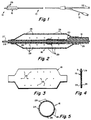
- FIG. 1 is an illustration of the balloon catheter used in the practice of the invention;
- FIG. 2 is an enlarged longitudinal cross-sectional illustration of the catheter taken through the region of the balloon as seen along the line 2-2 of FIG. 1;
- FIG. 3 is an illustration of the balloon laid flat showing the locations of holes as they may be formed by a laser;
- FIG. 4 is a side view of the flattened balloon as seen from an end thereof;
- FIG. 5 is a sectional illustration through the balloon illustrating the circumferential spacing of the rows of holes;
- FIG. 6 is an illustration of the balloon in a deflated condition prior to insertion of the balloon into a patient's artery;
- FIG. 7 is an enlarged illustration of the balloon portion of the catheter in an artery and in an inflated configuration; and
- FIG. 8 is an enlarged cross-sectional illustration of the boundary region of the balloon, fluid film and artery.
- FIG. 1 illustrates the catheter used in the practice of the invention. The catheter includes an elongate
flexible shaft 10 that may be formed in an extrusion process from an appropriate plastic material such as polyethylene. By way of example, when the catheter is intended to be used in the coronary arteries, the shaft may be of the order of 150 cm long and may have an outer diameter of 1.4 mm (.054"). The catheter has aproximal end 12 and adistal end 14. An inflatable and deflatable balloon, indicated generally at 16 is mounted on thedistal end 14 of thecatheter shaft 10. As shown in FIG. 2, thecatheter shaft 10 includes aninflation lumen 18 that extends from the proximal end of the shaft and terminates in anopening 20 within theballoon 16. Theproximal end 12 of thecatheter shaft 10 carries afitting 22 by which theinflation lumen 18 may be connected to a syringe (not shown) or other pressure fluid delivery device. Thecatheter shaft 10 also may be formed to include aguidewire lumen 26 that extends to and terminates in anoutlet orifice 28 at the distal tip of thecatheter shaft 10. Theguidewire lumen 26 may be used to receive aguidewire 27 by which the catheter may be guided through a patient's vasculature to the site to be treated. - The
balloon 16 may be formed from various polymeric materials and desirably has a thin, flexible, inelastic wall. A preferred material is polyethylene terephthalate and a balloon having a wall thickness of 0,025 mm (.001") or less may be fabricated as described in U.S. Patent 4,490,421 (Levy) or EP-A-0 279 411. By way of example, a catheter according to the invention adapted for use in the coronary arteries may have a balloon about 20 mm or more long and a wall thickness of 0.025 mm (.001") or less. It is contemplated that with a inelastic balloon several different sizes of (inflated) balloons may be required, depending on the application in which the catheter is to be used. For example, when used as an adjunct to angioplasty of the coronary arteries, balloons having diameters of 2.0 mm, 2.5 mm, 3.0 mm, 3.5 mm may be appropriate. In general, in connection with arterial angioplasty, it is contemplated that the balloon of the present invention should be selected to match the balloon used in the angioplasty procedure, the foregoing range being typical of the balloon sizes commonly employed in coronary angioplasty catheters. - The
balloon 16 is provided with a plurality ofminute holes 29 that are substantially regularly spaced about theballoon 16. For example, we have found that an array of about thirty holes, each about 25µm (microns) in diameter has been satisfactory. The holes may be formed by a laser beam from an excimer laser having wavelengths of 248 or 308 nm. These have been found to form clean edged holes in the balloon material. FIGS. 2 and 3 illustrate a satisfactory pattern of holes including six longitudinally extending rows having five holes 30 in each row. Some of the rows may be staggered longitudinally, with respect to each other as illustrated in FIG. 2. The holes are formed before the balloon is mounted on the catheter shaft. The balloon is laid flat as shown in FIG. 4 while a laser beam is used to drill theholes 29 in the desired pattern shown. In that pattern, the holes extend over a length of about 12 mm of the balloon and are located on 1.2 mm centers for a 3.0 mm diameter balloon. - The aggregate flow area defined by the
holes 29 is selected so that under the general range of inflation pressures expected, the liquid flow through the holes will be very low, weeping in nature, and will not exceed a predetermined maximum flow rate in atmosphere. Although the foregoing configuration of holes is believed to be satisfactory for a wide range, and possibly most, if not all, medications or drugs to be delivered, it is possible that certain medications or drugs may have viscosity and flow characteristics as might require modification to the holes. The foregoing array of holes has been found to produce satisfactorily low flow rates for fluid medications having a viscosity and fluid characteristic similar to saline (such as heparin). In accordance with a preferred embodiment of the invention, the maximum flow rate is between 2 to 12 ml (cc) per minute under inflation pressures of 0.2 - 0.5MPa (2 to 5 atmospheres). Additionally, it is important that theholes 29 do not define a flow area so large as would impair the ability of the balloon to be collapsed when the inflation lumen is aspirated. The flow area should be not so large that there is a significant fluid loss to any side branches that the balloon may be inflated across. This is after all the original problem with double balloon catheters and solved by the instant invention. Collapse of the balloon is necessary in order to permit the balloon to be withdrawn from the patient's vasculature. - Use of the catheter and practice of the method may be illustrated in arterial angioplasty, such as percutaneous transluminal coronary angioplasty. Typically, the angioplasty procedure will have been performed by the physician according to any of a variety of techniques using various angioplasty catheters available. For purposes of illustration, it may be assumed that the angioplasty procedure will have been performed either by a balloon catheter, laser catheter or other angioplasty catheter to enlarge the stenosed region to a luminal diameter of 2.5 mm. Typically, the arterial wall will display a certain amount of "recoil" after the angioplasty so that the luminal diameter may be slightly smaller than 2.5 mm. In order thereafter to treat the arterial wall with concentrated heparin (or an isolated heparin fraction having antiproliferative effect), the angioplasty catheter is removed from the patient, typically permitting. the guidewire to remain in place. The catheter of the present invention will have been prepared, as by the physician's assistant, to fill the
inflation lumen 18 and interior of theballoon 16 with the medication, taking care to purge the inflation and balloon system of air. The balloon then is wrapped about the catheter shaft to collapse the balloon to a low profile, as suggested by FIG. 6, by which it may be passed through the artery (or a guiding catheter leading to the coronary artery to be treated). The catheter then is advanced over the guidewire which guides the catheter to the site of the angioplasty. The catheter preferably is provided with one or more radiopaque marker bands by which the balloon position may be monitored under fluoroscopy to verify placement of the balloon in the region to be treated. Once the balloon is positioned within the site of the angioplasty, the syringe or other inflation device is operated to pressurize the catheter lumen and interior of the balloon to cause the balloon to inflate as suggested in FIG. 7. By proper selection of the balloon size, the balloon will inflate into close pressing contact with the inner surface of the arterial lumen, effecting intimate surface contact with the lumen. Pressure is applied continually at the inflation device (which may be fitted with a pressure gauge) to maintain a substantially constant pressure level as desired, the range of pressures anticipated being of the order of 0,2-0,5MPa(2 to 5 atmospheres). The pressure is sufficient to press the balloon firmly against the luminal surface of the artery but not so great as to preclude medication from weeping through theholes 29 in the balloon. As the medication weeps through the holes, it spreads into a generallycylindrical film 32 between theballoon 16 andartery wall 34. Because of the tendency of the balloon to intimately contact the artery wall, thefilm 32 will be maintained under pressure and will be forced into the arterial wall. Although there is some fluid pressure drop as the fluid weeps through theholes 29 and between the balloon and artery wall, the film pressure remains sufficiently high that the medication will progressively proliferate through the arterial tissue. The pressure and flow will be continued for a predetermined time, for example, one to two minutes, as is sufficient to achieve the desired penetration of medication into the arterial wall. Preferably, the holes are placed so that the end most of theholes 29 are spaced inwardly somewhat from the conical ends of the balloon thereby defining an annular portion at each end of the balloon which is unperforated and which may tend to have a partial sealing effect, tending to retard flow of the fluid from out between the balloon and the artery wall. The balloon then is deflated by aspirating through the inflation/deflation lumen to cause the balloon to collapse. The balloon catheter then is withdrawn from the patient. The flow area defined by the holes is sufficiently minute and the balloon wall is sufficiently flexible so that the balloon will collapse under aspiration. - By way of example, based on animal experiments conducted in accordance with the invention, the following penetrations of heparin through the tissue of an artery may be expected under the pressure levels for about one minutes.
Gage Pressure at Proximal Part of Catheter Estimated Average Pressure of Film in Contact with Artery Depth of Penetration Into Wall of Artery in 1 Minute Approximate Flow Rate of Unrestricted Catheter 0.2MPa(2 bar) 0-6.6KPa (0-50 mm Hg) (100µm(microns) 2 ml/min 0.3MPa(3 bar) 19.9-39.9KPa (150-300 mm Hg) (200µm(microns) 3 ml/min 0.4MPa(4 bar) 39.9-66.4KPa(300-500 mm Hg) (300-400µm(microns) 4 ml/min 0.5MPa(5 bar) 66.4-133KPa (500-1000 mm Hg) (500-700µm(microns) 5 ml/min - Thus, we have described the invention by which highly concentrated medication may be applied to a surface of a body lumen, such as an artery, under sufficient pressure to cause the medication to penetrate into the tissue without introducing excessively high volumes of the medication into the patient's system. It should be understood, however, that although the invention has been described principally in connection with post-angioplasty treatment of an artery with heparin or an antiproliferative fraction of heparin, the invention may be practised in any instance where it is desired to apply a high concentration of medication to a local vessel or organ having a lumen accessible by a catheter. Thus the invention may be used to deliver chemotherapeutic drugs in the treatment of cancer patients where it is desired to apply concentrated medication or chemotherapeutic agents to the diseased organ. The catheter may be passed into a lumen in the organ or may even be inserted into a lumen formed in the organ or tumor for the express purpose of receiving the catheter. Therefore, it should be understood that other embodiments and modifications of the invention may be apparent to those skilled in the art.
Claims (12)
- A catheter, for applying a liquid to a surface of the lumen of a body vessel, comprising an elongated flexible shaft (10), having a proximal end and a distal end with an inflation lumen (18) extending from its proximal toward its distal end, and a balloon (16), having a plurality of perforations (29), mounted on the distal end of the shaft, the interior of the balloon being in communication with the inflation lumen, characterised in that the balloon is flexible and substantially inelastic, the size and number of said perforations (29) and the thickness of the balloon wall are selected such that a saline solution can flow through the perforations at a rate of 2-12 ml/minute when it is supplied to the interior of the balloon (16) at a pressure of 0.2-0.5MPa (2-5 atmospheres), and the perforations (29) define a flow area sufficiently small so as not to adversely restrict collapsing of the balloon (16), about the catheter shaft (10), under the influence of aspiration applied to the inflation lumen, the catheter being for effecting penetration of the liquid into the body vessel.
- A catheter, for applying a liquid to a surface of the lumen of a body vessel, comprising an elongated flexible shaft (10), having a proximal end and a distal end with an inflation lumen (18) extending from its proximal toward its distal end, and a balloon (16), having a plurality of perforations (29), mounted on the distal end of the shaft, the interior of the balloon being in communication with the inflation lumen, characterised in that the balloon is flexible and substantially inelastic, the size and number of said perforations (29) and the thickness of the balloon wall are selected such that a saline solution can flow through the perforations at a rate of up to 12 ml/minute when it is supplied to the interior of the balloon (16) at a pressure of about 0.5MPa (5 atmospheres), and the perforations (29) define a flow area sufficiently small so as not to adversely restrict collapsing of the balloon (16), about the catheter shaft (10), under the influence of aspiration applied to the inflation lumen, the catheter being for effecting penetration of the liquid into the body vessel.
- A catheter as claimed in claim 1 or claim 2, characterised in that the flow rate through the perforations is 2-5ml/minute.
- A catheter as claimed in claim 1 or claim 2, characterised in that the flow rate through the perforations is about 1 ml/minute per 0.1 MPa (1 atmosphere) of pressure applied to the saline supplied to the balloon.
- A catheter as claimed in any of the preceding claims, characterised in that the balloon (16) has an inflated diameter of 2-3.5mm.
- A catheter as claimed in any of the preceding claims characterised in that the balloon (16) is formed from polyethylene terephthalate.
- A catheter as claimed in any of the preceding claims characterised in that the balloon (16) is provided with about thirty (29) substantially regularly spaced perforations (29), each having a diameter of about 25µm (microns), and the thickness of the balloon (16) wall is 0.025mm (.001") or less.
- A catheter as claimed in claim 7 characterised in that the catheter is dimensioned and adapted to be percutaneously inserted and advanced into the coronary arteries.
- A catheter as claimed in any preceding claim characterised in that the balloon (16) includes a cylindrical perforated surface having an annular portion at each end that is free of perforations.
- A catheter as claimed in any preceding claim characterised in that the pressure is 0.4MPa (4 atmospheres).
- A catheter as claimed in any of claims 1-9 characterised in that the pressure is 0.3MPa (3 atmospheres).
- A catheter as claimed in any of claims 1-9 characterised in that the pressure is 0.2MPa (2 atmospheres).
Applications Claiming Priority (2)
| Application Number | Priority Date | Filing Date | Title |
|---|---|---|---|
| US30435289A | 1989-01-31 | 1989-01-31 | |
| US304352 | 1989-01-31 |
Publications (3)
| Publication Number | Publication Date |
|---|---|
| EP0383429A2 EP0383429A2 (en) | 1990-08-22 |
| EP0383429A3 EP0383429A3 (en) | 1991-03-27 |
| EP0383429B1 true EP0383429B1 (en) | 1995-11-08 |
Family
ID=23176164
Family Applications (1)
| Application Number | Title | Priority Date | Filing Date |
|---|---|---|---|
| EP19900300438 Expired - Lifetime EP0383429B1 (en) | 1989-01-31 | 1990-01-16 | Catheter and method for locally applying medication to the wall of a blood vessel or other body lumen |
Country Status (5)
| Country | Link |
|---|---|
| EP (1) | EP0383429B1 (en) |
| JP (1) | JP2935522B2 (en) |
| CA (1) | CA2008915C (en) |
| DE (1) | DE69023362T2 (en) |
| ES (1) | ES2078936T3 (en) |
Cited By (11)
| Publication number | Priority date | Publication date | Assignee | Title |
|---|---|---|---|---|
| US5797877A (en) | 1993-10-01 | 1998-08-25 | Boston Scientific Corporation | Medical device balloons containing thermoplastic elastomers |
| US6132824A (en) | 1989-09-25 | 2000-10-17 | Schneider (Usa) Inc. | Multilayer catheter balloon |
| US6136258A (en) | 1991-04-26 | 2000-10-24 | Boston Scientific Corporation | Method of forming a co-extruded balloon for medical purposes |
| US7654264B2 (en) | 2006-07-18 | 2010-02-02 | Nellcor Puritan Bennett Llc | Medical tube including an inflatable cuff having a notched collar |
| US7781038B2 (en) | 1993-10-01 | 2010-08-24 | Boston Scientific Scimed, Inc. | Medical device balloons containing thermoplastic elastomers |
| US8597720B2 (en) | 2007-01-21 | 2013-12-03 | Hemoteq Ag | Medical product for treating stenosis of body passages and for preventing threatening restenosis |
| US8669360B2 (en) | 2011-08-05 | 2014-03-11 | Boston Scientific Scimed, Inc. | Methods of converting amorphous drug substance into crystalline form |
| US8889211B2 (en) | 2010-09-02 | 2014-11-18 | Boston Scientific Scimed, Inc. | Coating process for drug delivery balloons using heat-induced rewrap memory |
| US9050442B2 (en) | 1999-01-25 | 2015-06-09 | Atrium Medical Corporation | Expandable fluoropolymer device for delivery of therapeutic agents and method of making |
| US9056152B2 (en) | 2011-08-25 | 2015-06-16 | Boston Scientific Scimed, Inc. | Medical device with crystalline drug coating |
| US9192697B2 (en) | 2007-07-03 | 2015-11-24 | Hemoteq Ag | Balloon catheter for treating stenosis of body passages and for preventing threatening restenosis |
Families Citing this family (28)
| Publication number | Priority date | Publication date | Assignee | Title |
|---|---|---|---|---|
| US4994033A (en) * | 1989-05-25 | 1991-02-19 | Schneider (Usa) Inc. | Intravascular drug delivery dilatation catheter |
| US5116318A (en) * | 1989-06-06 | 1992-05-26 | Cordis Corporation | Dilatation balloon within an elastic sleeve |
| US5102402A (en) | 1991-01-04 | 1992-04-07 | Medtronic, Inc. | Releasable coatings on balloon catheters |
| US5318531A (en) * | 1991-06-11 | 1994-06-07 | Cordis Corporation | Infusion balloon catheter |
| US5213576A (en) * | 1991-06-11 | 1993-05-25 | Cordis Corporation | Therapeutic porous balloon catheter |
| US5429582A (en) * | 1991-06-14 | 1995-07-04 | Williams; Jeffery A. | Tumor treatment |
| CA2074304C (en) * | 1991-08-02 | 1996-11-26 | Cyril J. Schweich, Jr. | Drug delivery catheter |
| US5270047A (en) * | 1991-11-21 | 1993-12-14 | Kauffman Raymond F | Local delivery of dipyridamole for the treatment of proliferative diseases |
| US5306250A (en) * | 1992-04-02 | 1994-04-26 | Indiana University Foundation | Method and apparatus for intravascular drug delivery |
| DE4310378A1 (en) * | 1993-03-30 | 1994-10-06 | Aigner Karl | Balloon catheter and device for isolated perfusion by means of the balloon catheter |
| JP3403233B2 (en) * | 1994-01-20 | 2003-05-06 | テルモ株式会社 | Balloon catheter |
| US5415636A (en) * | 1994-04-13 | 1995-05-16 | Schneider (Usa) Inc | Dilation-drug delivery catheter |
| US5514092A (en) * | 1994-08-08 | 1996-05-07 | Schneider (Usa) Inc. | Drug delivery and dilatation-drug delivery catheters in a rapid exchange configuration |
| CA2216646A1 (en) * | 1995-03-31 | 1996-10-03 | Boston Scientific Corporation | Multiple hole drug delivery balloon |
| JPH09117510A (en) * | 1995-10-26 | 1997-05-06 | Buaayu:Kk | Infusion catheter |
| US6048332A (en) * | 1998-10-09 | 2000-04-11 | Ave Connaught | Dimpled porous infusion balloon |
| AU1017900A (en) * | 1998-11-02 | 2000-05-22 | Pro-Med Technology Consult Medizinisch-Technische Gerate Gmb H | End piece for a catheter or the like, perfusion catheter and perfusion catheter systems |
| US6395208B1 (en) | 1999-01-25 | 2002-05-28 | Atrium Medical Corporation | Method of making an expandable fluoropolymer device |
| US7481790B2 (en) | 2000-12-27 | 2009-01-27 | Advanced Cardiovascular Systems, Inc. | Vessel enlargement by arteriogenic factor delivery |
| JP3612581B2 (en) * | 2001-06-18 | 2005-01-19 | 哲 吉田 | Balloon type drug solution syringe for blood vessels |
| WO2011005421A2 (en) | 2009-07-10 | 2011-01-13 | Boston Scientific Scimed, Inc. | Use of nanocrystals for a drug delivery balloon |
| EP2453938B1 (en) | 2009-07-17 | 2015-08-19 | Boston Scientific Scimed, Inc. | Nucleation of drug delivery balloons to provide improved crystal size and density |
| KR20120098624A (en) | 2009-10-16 | 2012-09-05 | 헤모텍 아게 | Use of compositions to coat catheter balloons and coated catheter balloons |
| DE102010022588A1 (en) | 2010-05-27 | 2011-12-01 | Hemoteq Ag | Balloon catheter with a particle-free drug-releasing coating |
| WO2013007273A1 (en) | 2011-07-08 | 2013-01-17 | Cardionovum Sp.Z.O.O. | Balloon surface coating |
| CN110292703A (en) * | 2019-08-15 | 2019-10-01 | 河南中医药大学第一附属医院 | A kind of double sacculus precisely quantify injection catheter |
| CN112274745A (en) * | 2020-10-29 | 2021-01-29 | 合肥达米医疗科技有限公司 | Double-layer bag double-cavity bronchial catheter |
| CN116407210A (en) * | 2021-12-31 | 2023-07-11 | 苏州天鸿盛捷医疗器械有限公司 | Vascular stenosis treatment device |
Family Cites Families (4)
| Publication number | Priority date | Publication date | Assignee | Title |
|---|---|---|---|---|
| US4490421A (en) * | 1983-07-05 | 1984-12-25 | E. I. Du Pont De Nemours And Company | Balloon and manufacture thereof |
| DE3516830A1 (en) * | 1985-05-10 | 1986-11-13 | Max Dr. 8520 Erlangen Hubmann | CATHETER |
| US4821722A (en) * | 1987-01-06 | 1989-04-18 | Advanced Cardiovascular Systems, Inc. | Self-venting balloon dilatation catheter and method |
| DE8904026U1 (en) * | 1988-04-20 | 1989-05-24 | Schneider (Europe) Ag, Zuerich, Ch |
-
1990
- 1990-01-16 DE DE1990623362 patent/DE69023362T2/en not_active Expired - Fee Related
- 1990-01-16 EP EP19900300438 patent/EP0383429B1/en not_active Expired - Lifetime
- 1990-01-16 ES ES90300438T patent/ES2078936T3/en not_active Expired - Lifetime
- 1990-01-30 CA CA002008915A patent/CA2008915C/en not_active Expired - Fee Related
- 1990-01-30 JP JP2020377A patent/JP2935522B2/en not_active Expired - Fee Related
Cited By (14)
| Publication number | Priority date | Publication date | Assignee | Title |
|---|---|---|---|---|
| US6132824A (en) | 1989-09-25 | 2000-10-17 | Schneider (Usa) Inc. | Multilayer catheter balloon |
| US6136258A (en) | 1991-04-26 | 2000-10-24 | Boston Scientific Corporation | Method of forming a co-extruded balloon for medical purposes |
| US6482348B1 (en) | 1991-04-26 | 2002-11-19 | Boston Scientific Corporation | Method of forming a co-extruded balloon for medical purposes |
| US7781038B2 (en) | 1993-10-01 | 2010-08-24 | Boston Scientific Scimed, Inc. | Medical device balloons containing thermoplastic elastomers |
| US6086556A (en) | 1993-10-01 | 2000-07-11 | Boston Scientific Corporation | Medical device balloons containing thermoplastic elastomers |
| US5797877A (en) | 1993-10-01 | 1998-08-25 | Boston Scientific Corporation | Medical device balloons containing thermoplastic elastomers |
| US9050442B2 (en) | 1999-01-25 | 2015-06-09 | Atrium Medical Corporation | Expandable fluoropolymer device for delivery of therapeutic agents and method of making |
| US7654264B2 (en) | 2006-07-18 | 2010-02-02 | Nellcor Puritan Bennett Llc | Medical tube including an inflatable cuff having a notched collar |
| US8096299B2 (en) | 2006-07-18 | 2012-01-17 | Nellcor Puritan Bennett Llc | Medical tube including an inflatable cuff having a notched collar |
| US8597720B2 (en) | 2007-01-21 | 2013-12-03 | Hemoteq Ag | Medical product for treating stenosis of body passages and for preventing threatening restenosis |
| US9192697B2 (en) | 2007-07-03 | 2015-11-24 | Hemoteq Ag | Balloon catheter for treating stenosis of body passages and for preventing threatening restenosis |
| US8889211B2 (en) | 2010-09-02 | 2014-11-18 | Boston Scientific Scimed, Inc. | Coating process for drug delivery balloons using heat-induced rewrap memory |
| US8669360B2 (en) | 2011-08-05 | 2014-03-11 | Boston Scientific Scimed, Inc. | Methods of converting amorphous drug substance into crystalline form |
| US9056152B2 (en) | 2011-08-25 | 2015-06-16 | Boston Scientific Scimed, Inc. | Medical device with crystalline drug coating |
Also Published As
| Publication number | Publication date |
|---|---|
| DE69023362T2 (en) | 1996-04-04 |
| ES2078936T3 (en) | 1996-01-01 |
| CA2008915C (en) | 1996-06-11 |
| DE69023362D1 (en) | 1995-12-14 |
| JPH02283380A (en) | 1990-11-20 |
| EP0383429A2 (en) | 1990-08-22 |
| JP2935522B2 (en) | 1999-08-16 |
| CA2008915A1 (en) | 1990-07-31 |
| EP0383429A3 (en) | 1991-03-27 |
Similar Documents
| Publication | Publication Date | Title |
|---|---|---|
| EP0383429B1 (en) | Catheter and method for locally applying medication to the wall of a blood vessel or other body lumen | |
| US5087244A (en) | Catheter and method for locally applying medication to the wall of a blood vessel or other body lumen | |
| US8317747B2 (en) | Catheter for tissue dilation and drug delivery | |
| US5464395A (en) | Catheter for delivering therapeutic and/or diagnostic agents to the tissue surrounding a bodily passageway | |
| US7621895B2 (en) | Needle array devices and methods | |
| US5910101A (en) | Device for loading and centering a vascular radiation therapy source | |
| US5611775A (en) | Method of delivery therapeutic or diagnostic liquid into tissue surrounding a body lumen | |
| US5876426A (en) | System and method of providing a blood-free interface for intravascular light delivery | |
| US5021044A (en) | Catheter for even distribution of therapeutic fluids | |
| US5851171A (en) | Catheter assembly for centering a radiation source within a body lumen | |
| KR930002271B1 (en) | Intravascular drug delivery dilatation catheter | |
| US6706013B1 (en) | Variable length drug delivery catheter | |
| US6280414B1 (en) | Method and apparatus for local delivery of therapeutic agent | |
| US6159139A (en) | Radiation delivery catheter with a spring wire centering mechanism | |
| US5370617A (en) | Blood perfusion balloon catheter | |
| CA2585639C (en) | Catheter assembly with plaque cutting balloon | |
| US6547767B1 (en) | Syringe assembly for a catheter | |
| US20030040712A1 (en) | Substance delivery apparatus and a method of delivering a therapeutic substance to an anatomical passageway | |
| JP2004538036A (en) | Drug delivery catheter with high compliant balloon with injection hole | |
| US6224535B1 (en) | Radiation centering catheters | |
| WO1997017099A1 (en) | Balloon catheter for drug application | |
| AU4408193A (en) | Dual dilatation balloon and infusion balloon catheter | |
| WO1999040971A1 (en) | Radiation delivery catheter with blood perfusion capability |
Legal Events
| Date | Code | Title | Description |
|---|---|---|---|
| PUAI | Public reference made under article 153(3) epc to a published international application that has entered the european phase |
Free format text: ORIGINAL CODE: 0009012 |
|
| AK | Designated contracting states |
Kind code of ref document: A2 Designated state(s): DE ES FR GB IT NL |
|
| PUAL | Search report despatched |
Free format text: ORIGINAL CODE: 0009013 |
|
| AK | Designated contracting states |
Kind code of ref document: A3 Designated state(s): DE ES FR GB IT NL |
|
| 17P | Request for examination filed |
Effective date: 19910802 |
|
| 17Q | First examination report despatched |
Effective date: 19921029 |
|
| GRAA | (expected) grant |
Free format text: ORIGINAL CODE: 0009210 |
|
| AK | Designated contracting states |
Kind code of ref document: B1 Designated state(s): DE ES FR GB IT NL |
|
| REF | Corresponds to: |
Ref document number: 69023362 Country of ref document: DE Date of ref document: 19951214 |
|
| REG | Reference to a national code |
Ref country code: ES Ref legal event code: FG2A Ref document number: 2078936 Country of ref document: ES Kind code of ref document: T3 |
|
| ITF | It: translation for a ep patent filed |
Owner name: STUDIO TORTA SOCIETA' SEMPLICE |
|
| ET | Fr: translation filed | ||
| PLBE | No opposition filed within time limit |
Free format text: ORIGINAL CODE: 0009261 |
|
| STAA | Information on the status of an ep patent application or granted ep patent |
Free format text: STATUS: NO OPPOSITION FILED WITHIN TIME LIMIT |
|
| 26N | No opposition filed | ||
| PGFP | Annual fee paid to national office [announced via postgrant information from national office to epo] |
Ref country code: ES Payment date: 20000121 Year of fee payment: 11 |
|
| NLS | Nl: assignments of ep-patents |
Owner name: MEDTRONIC AVE, INC.;ARTERIAL VASCULAR ENGINEERING, |
|
| REG | Reference to a national code |
Ref country code: FR Ref legal event code: TP |
|
| REG | Reference to a national code |
Ref country code: GB Ref legal event code: 732E |
|
| PG25 | Lapsed in a contracting state [announced via postgrant information from national office to epo] |
Ref country code: ES Free format text: LAPSE BECAUSE OF NON-PAYMENT OF DUE FEES Effective date: 20010117 |
|
| REG | Reference to a national code |
Ref country code: GB Ref legal event code: IF02 |
|
| REG | Reference to a national code |
Ref country code: ES Ref legal event code: FD2A Effective date: 20021016 |
|
| PGFP | Annual fee paid to national office [announced via postgrant information from national office to epo] |
Ref country code: NL Payment date: 20021216 Year of fee payment: 14 |
|
| PGFP | Annual fee paid to national office [announced via postgrant information from national office to epo] |
Ref country code: GB Payment date: 20031211 Year of fee payment: 15 |
|
| PGFP | Annual fee paid to national office [announced via postgrant information from national office to epo] |
Ref country code: DE Payment date: 20040130 Year of fee payment: 15 |
|
| PG25 | Lapsed in a contracting state [announced via postgrant information from national office to epo] |
Ref country code: NL Free format text: LAPSE BECAUSE OF NON-PAYMENT OF DUE FEES Effective date: 20040801 |
|
| NLV4 | Nl: lapsed or anulled due to non-payment of the annual fee |
Effective date: 20040801 |
|
| PG25 | Lapsed in a contracting state [announced via postgrant information from national office to epo] |
Ref country code: IT Free format text: LAPSE BECAUSE OF NON-PAYMENT OF DUE FEES;WARNING: LAPSES OF ITALIAN PATENTS WITH EFFECTIVE DATE BEFORE 2007 MAY HAVE OCCURRED AT ANY TIME BEFORE 2007. THE CORRECT EFFECTIVE DATE MAY BE DIFFERENT FROM THE ONE RECORDED. Effective date: 20050116 Ref country code: GB Free format text: LAPSE BECAUSE OF NON-PAYMENT OF DUE FEES Effective date: 20050116 |
|
| PG25 | Lapsed in a contracting state [announced via postgrant information from national office to epo] |
Ref country code: DE Free format text: LAPSE BECAUSE OF NON-PAYMENT OF DUE FEES Effective date: 20050802 |
|
| GBPC | Gb: european patent ceased through non-payment of renewal fee |
Effective date: 20050116 |
|
| PGFP | Annual fee paid to national office [announced via postgrant information from national office to epo] |
Ref country code: FR Payment date: 20060104 Year of fee payment: 17 |
|
| REG | Reference to a national code |
Ref country code: FR Ref legal event code: ST Effective date: 20070930 |
|
| PG25 | Lapsed in a contracting state [announced via postgrant information from national office to epo] |
Ref country code: FR Free format text: LAPSE BECAUSE OF NON-PAYMENT OF DUE FEES Effective date: 20070131 |