EP0404592A1 - NMR probe with multiple isolated coplanar surface coils - Google Patents
NMR probe with multiple isolated coplanar surface coils Download PDFInfo
- Publication number
- EP0404592A1 EP0404592A1 EP90306861A EP90306861A EP0404592A1 EP 0404592 A1 EP0404592 A1 EP 0404592A1 EP 90306861 A EP90306861 A EP 90306861A EP 90306861 A EP90306861 A EP 90306861A EP 0404592 A1 EP0404592 A1 EP 0404592A1
- Authority
- EP
- European Patent Office
- Prior art keywords
- coil
- circular
- probe
- surface coil
- nmr
- Prior art date
- Legal status (The legal status is an assumption and is not a legal conclusion. Google has not performed a legal analysis and makes no representation as to the accuracy of the status listed.)
- Withdrawn
Links
Images
Classifications
-
- G—PHYSICS
- G01—MEASURING; TESTING
- G01R—MEASURING ELECTRIC VARIABLES; MEASURING MAGNETIC VARIABLES
- G01R33/00—Arrangements or instruments for measuring magnetic variables
- G01R33/20—Arrangements or instruments for measuring magnetic variables involving magnetic resonance
- G01R33/28—Details of apparatus provided for in groups G01R33/44 - G01R33/64
- G01R33/32—Excitation or detection systems, e.g. using radio frequency signals
- G01R33/34—Constructional details, e.g. resonators, specially adapted to MR
- G01R33/341—Constructional details, e.g. resonators, specially adapted to MR comprising surface coils
Definitions
- the present invention relates to nuclear magnetic resonance (NMR) apparatus and, more particularly, to novel NMR antenna probes utilizing a plurality of surface coils, (i.e. a conductor or a plurality of conductors, with or without added impedance elements, which are arranged and substantially confined initially to a flat plane, even if that flat plane is later to be conformed to the shape of a sample of interest, for actual use in exciting and/or detecting/receiving NMR signals), arranged in substantially coaxial and coplanar geometry and having improved electronic isolation therebetween.
- a plurality of surface coils i.e. a conductor or a plurality of conductors, with or without added impedance elements, which are arranged and substantially confined initially to a flat plane, even if that flat plane is later to be conformed to the shape of a sample of interest, for actual use in exciting and/or detecting/receiving NMR signals
- NMR reception (or detection) antennae it is well known to utilize surface coils as NMR reception (or detection) antennae, particularly for spectroscopic studies of the head, torso and the like, because such coils provide a better signal-to-noise ratio than volume coils.
- Surface coils are also commonly used for excitation in spectroscopic studies because the excitation field is more localized, so that less radio-frequency (RF) power is required. Due to increased bandwidth requirements, the RF power required to stimulate NMR nuclei other than hydrogen (1H) may become excessive; in some cases, this leads to undesirable RF power levels in the sample (e.g. a human body portion) under study, as nuclei such as phosphorus (31P) or carbon (13C) are studied.
- RF radio-frequency
- a NMR antenna probe comprises: at least one surface coil, of spiral or substantially circular form, arranged in a plane; and a surface coil having a substantially non-circular shape, located substantially coplanar with the at least one circular surface coil, having a center portion which is located substantially coaxial with the axis of the at least one circular surface coil, and providing a RF field substantially orthogonal to the RF field provided by each of the at least one substantially circular surface coil.
- the coil corresponding to the least-NMR-sensitive nucleus is of substantially-circular form, while the non-circular coil (sensitive to the field perpendicular to that of the substantially-circular coil(s)) corresponds (is tuned) to the most-NMR-sensitive nucleus.
- the circular coil is positioned on the side of the NMR probe closest to the subject to be studied.
- one multiple-turn circular surface coil of about 6.5 centimeter diameter is positioned in front of a non-circular and substantially-coplanar Figure-8 surface coil having a width of about 8 centimeters and a length of about 13 centimeters, to provide mutual coupling interaction on the order of a magnitude less (e.g. about 6%) than the coupling interaction between a pair of similarly sized but substantially coplanar and coaxial circular surface coils tuned to the same frequencies.
- the present invention to provide a NMR probe antenna having at least one surface coil of a first group with reduced mutual coupling interaction to a coplanar surface coil of another group.
- a presently preferred embodiment of a NMR antenna probe 10 utilizes a multiple-turn, substantially circular surface coil 11 (which includes spiral-shaped coils) of a first group of at least one surface coil; coil 11 (shown here in broken line) has a reduced mutual coupling interaction with another surface coil antenna 12 of another surface coil group.
- the circular surface coil 11 is tuned, as by a plurality of (capacitive) tuning elements 11t-1 through 11t-4, to a first NMR frequency, of a lesser-NMR-sensitive species (such as 13C, 31P, and the like) of nuclei or of the NMR species of primary interest, while the non-circular surface coil 12 is tuned, as by a plurality of tuning devices 12t-1 through 12t-5, to the most-NMR-sensitive nuclear species (e.g. 1H) or of a species of less interest utilized in the study.
- the at least one circular surface coil 11 is positioned on a surface of a thin, insulative, non-magnetic sheet 14 closest to the subject to be studied, while the non-circular surface 12 is positioned on that sheet surface 14a furthest from the sample.
- Coils 11 and 12 can be etched from separated layers of conductive material, each fabricated on an opposite side of sheet 14.
- the insulative sheet 14 has a thickness at least in order of magnitude less than the diameter of any substantially circular coil.
- the insulative sheet 14 is sufficiently rigid to support the coils 11 and 12.
- the substantially-circular surface coil(s) 11 include any surface coil with substantially coplanar windings, of less than, equal to or more than a single turn, with any shape which produces an RF magnetic field B l,O in a direction perpendicular to the plane of the winding(s) of the coil.
- Substantially-circular coils specifically include regular geometrically shaped coils of E equal sides (where E is at least 1).
- Surface coil 11 may be a single surface coil or a plurality of substantially coaxial and coplanar surface coils. A single surface coil of two circular-spiral turns is illustrated, although single turn surface coils, or coils with more turns, can be equally as well utilized.
- the illustrated multiple-turn circular-spiral coil 11 is formed about a central axis 10a of the probe, which happens to coincide with the center of sheet 14.
- a first circular-spiral-shaped surface coil end 11a is connected by an extended conductive portion, 11-1 to starting point 11b of the circular turns.
- the circular coil portion 11′ includes a first reactive tuning element 11t-1 in the first quarter-turn portion 11c thereof.
- Another reactive tuning element 11t-2 (here, a variable tuning element) may be provided in a second or third quarter-turn portion 11d or 11e, with further reactive (preferably capacitive) tuning elements 11t-3, 11t4,...in the subsequent coil sections 11f, 11g, 11i,... .
- the circular portion of the coil ends at point 11j, and a jumper conductor portion 11k is brought through to the other side of the insulative member 14, to a point 11l, at which point the conductor returns to the first side of the insulative member, where a second conductive extended portion 11-2 is utilized to bring the circular surface coil to its termination point 11m.
- Suitable cable, impedance matching and/or balanced-to-unbalanced transformation means can be attached to the circular surface coils terminals 11a/11m, as well known to the art.
- the average radius R of the circular surface coil is about 3 and one-quarter centimeters.
- the non-circular surface coil 12 illustratively of a Figure-8 configuration, is of any configuration such that its RF field B 1,8 is in the plane of sheet 14 and is therefore essentially orthogonal to the RF field B 1,0 (into and out of the sheet 14 plane) which the circular surface coil 11 would produce, if each of surface coils 11 and 12 were similarly, but individually, excited by the same RF signals used with the circular/non-circular probe.
- Figure-8 surface coil 12 commences at a first terminal 12a, which is connected by a first conductive extended lead portion 12-1, to a first coil point 12b.
- the Figure-8 coil conductor 12′ has a first section 12-2 extending in a first direction (e.g.
- section 12-3 is integrally joined thereto and extends in a direction (e.g. vertically along the length of sheet 14) substantially perpendicular to the direction in which section 12-2 extends.
- a slanted section 12e traverses across the member 14 to an opposite inner corner 12f, at which a section 12-4 commences.
- Section 12-4 is parallel to section 12-3, being in the same (e.g. vertical, or lengthwise) direction.
- the coil conductor 12′ turns substantially perpendicular at a left bottom outer corner 12g, diagonally opposite top right outer corner 12c, with respect to the probe center point 10a (which is also the center of both coils 11 and 12).
- a bottom portion 12-5 extends from corner 12g to an opposite, outer right outer corner 12h, with another portion 12-6 extending upwardly therefrom towards portion 12-3, until a third inner corner 12i is reached.
- a second slanted traverse portion 12j crosses the sheet, with an insulative cross-over portion 12e occurring substantially in the region of probe center point 10a, and facilitated by a sheet 16 of an insulation material.
- the second cross-over portion 12j turns at a fourth inner corner 12k, going through a final vertical section 12-7, before turning at a top left outer corner 12l and going through a final horizontal section 12-i until final corner 12m is turned and a second extended conductive section 12-9 brings the Figure-8 coil to its second terminal 12n.
- a plurality of reactive means such as capacitors 12t-1 through 12t-5, are used to tune coil 12 to the required NMR frequency here, variable capacitor 12t-3 is centrally located and used to fine tune to the 1H frequency.
- additional balanced conductive means, impedance matching means and/or balanced-to-unbalanced RF means can be utilized, in manner well known to the art, to affect connection of a coaxial RF cable to the external-connection terminals 12a and 12n of the Figure-8 coil 12.
- a Figure-8 coil 12 having a width W of about 8 centimeters and a length L of about 13 centimeters has proved useful in conducting 1H/31P studies in a 1.5 Tesla NMR spectroscopy system.
- any figure-8 pattern of two crossing loops, with curved or straight conductive sections, can be used, as long as the magnetic field B 1,8 thereof is substantially parallel to the plane of the loop sections; multiple turns can also be used.
- the coil need not be symmetrical about either axis, as any mutual coupling introduced by coil asymmetry may be minimized by adjustment of the locations of the coils with respect to one another, but within the common plane.
- each probe while described as being formed substantially in a flat plane, is contemplated for use by warping/bending the initially-planar probe into a shape conforming to the surface of an object to be studied. Accordingly, the invention is not limited to or by the specific details and instrumentalities presented by way of explanation herein.
Abstract
An NMR antenna probe (10) has at least one substantially circular surface coil (11) arranged in a plane and a non-circular surface coil (12) which is preferably of substantially figure-8 shape and is substantially coplanar with the at least one circular surface coil. The figure-8 coil has a cross-over portion which is located substantially coaxial with the axis of the at least one circular surface coil. The circular coil corresponds to the least-NMR-sensitive nucleus, while the non-circular coil corresponds to the most-NMR-sensitive nucleus. The circular coil is positioned on the side of the NMR probe closest to the subject to be studied.
Description
- The present invention relates to nuclear magnetic resonance (NMR) apparatus and, more particularly, to novel NMR antenna probes utilizing a plurality of surface coils, (i.e. a conductor or a plurality of conductors, with or without added impedance elements, which are arranged and substantially confined initially to a flat plane, even if that flat plane is later to be conformed to the shape of a sample of interest, for actual use in exciting and/or detecting/receiving NMR signals), arranged in substantially coaxial and coplanar geometry and having improved electronic isolation therebetween.
- It is well known to utilize surface coils as NMR reception (or detection) antennae, particularly for spectroscopic studies of the head, torso and the like, because such coils provide a better signal-to-noise ratio than volume coils. Surface coils are also commonly used for excitation in spectroscopic studies because the excitation field is more localized, so that less radio-frequency (RF) power is required. Due to increased bandwidth requirements, the RF power required to stimulate NMR nuclei other than hydrogen (¹H) may become excessive; in some cases, this leads to undesirable RF power levels in the sample (e.g. a human body portion) under study, as nuclei such as phosphorus (³¹P) or carbon (¹³C) are studied. It is highly desirable to utilize simple circular or polygonal surface coils for reception, as these surface coils are most sensitive in such studies. It is often desirable to utilize separate surface coils for transmission of the excitation signal and for reception of the NMR response signal. Situations in which separate transmission/reception surface coils may be used include: heteronuclear NMR studies, where one coil is used for exciting a first species of nucleus, and a second coil is used for exciting and/or detecting a second species of nucleus, as in a ¹H-decoupled, nuclear Overhauser enhanced, in vivo ¹³C experiment, or in a ¹H-decoupled in vivo ³¹P experiment; in a heteronuclear NMR study where a first coil is tuned and used for excitation of ¹H images and a second coil is used for excitation and/or detection of NMR spectroscopy signals from the sample; in a homonuclear study utilizing selective irradiation of one chemical species with a first coil and utilizing a second coil for excitation and/or detection of NMR signals from at least one chemically different species of the same NMR nucleus; or a homonuclear study where a first coil is used for excitation (e.g. to provide a uniform excitation field over a region of a sample), and a second coil is utilized for detection. The foregoing experiment types encompass the vast majority of NMR spectroscopy studies performed at this time.
- It is also well known that use of a pair of circular or polygonal surface coils, positioned to produce fields that are substantially coaxial with one another, provide a degree of mutual electrical coupling between the coils which seriously compromises performance of the probe utilizing the pair of coils. Often, the performance of the higher-frequency coil (i.e. that surface coil tuned to the higher NMR frequency, e.g. to the ¹H frequency) is rendered useless, and diode-blocking or other active blocking networks cannot be employed for decoupling studies. Thus, in ¹H-decoupled spectroscopy, where a high level decoupling signal must be provided during the time interval when spectra are actually acquired, the mutual interaction between the decoupling coil and spectra-reception coils will prevent acquisition of the NMR response signal by the latter (detection) coil. It is therefore highly desirable to provide a NMR probe antenna, having a plurality of surface coils, in which at least a pair of the surface coils do not substantially interact, even though those coils are substantially coplanar and coaxial with one another.
- In accordance with the invention, a NMR antenna probe comprises: at least one surface coil, of spiral or substantially circular form, arranged in a plane; and a surface coil having a substantially non-circular shape, located substantially coplanar with the at least one circular surface coil, having a center portion which is located substantially coaxial with the axis of the at least one circular surface coil, and providing a RF field substantially orthogonal to the RF field provided by each of the at least one substantially circular surface coil. The coil corresponding to the least-NMR-sensitive nucleus is of substantially-circular form, while the non-circular coil (sensitive to the field perpendicular to that of the substantially-circular coil(s)) corresponds (is tuned) to the most-NMR-sensitive nucleus. The circular coil is positioned on the side of the NMR probe closest to the subject to be studied.
- In a presently preferred embodiment, one multiple-turn circular surface coil of about 6.5 centimeter diameter is positioned in front of a non-circular and substantially-coplanar Figure-8 surface coil having a width of about 8 centimeters and a length of about 13 centimeters, to provide mutual coupling interaction on the order of a magnitude less (e.g. about 6%) than the coupling interaction between a pair of similarly sized but substantially coplanar and coaxial circular surface coils tuned to the same frequencies.
- Accordingly, it is possible by the present invention to provide a NMR probe antenna having at least one surface coil of a first group with reduced mutual coupling interaction to a coplanar surface coil of another group.
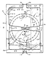
- The foregoing and other aspects of the invention will become apparent upon reading of the following detailed description taken in conjunction with the accompanying drawing, the sole Figure of which is a plan view of a NMR probe antenna in accordance with the present invention.
- Referring to the sole figure, a presently preferred embodiment of a
NMR antenna probe 10 utilizes a multiple-turn, substantially circular surface coil 11 (which includes spiral-shaped coils) of a first group of at least one surface coil; coil 11 (shown here in broken line) has a reduced mutual coupling interaction with anothersurface coil antenna 12 of another surface coil group. Thecircular surface coil 11 is tuned, as by a plurality of (capacitive)tuning elements 11t-1 through 11t-4, to a first NMR frequency, of a lesser-NMR-sensitive species (such as ¹³C, ³¹P, and the like) of nuclei or of the NMR species of primary interest, while thenon-circular surface coil 12 is tuned, as by a plurality of tuning devices 12t-1 through 12t-5, to the most-NMR-sensitive nuclear species (e.g. ¹H) or of a species of less interest utilized in the study. The at least onecircular surface coil 11 is positioned on a surface of a thin, insulative,non-magnetic sheet 14 closest to the subject to be studied, while thenon-circular surface 12 is positioned on that sheet surface 14a furthest from the sample. -
Coils sheet 14. Theinsulative sheet 14 has a thickness at least in order of magnitude less than the diameter of any substantially circular coil. Theinsulative sheet 14 is sufficiently rigid to support thecoils - The substantially-circular surface coil(s) 11 include any surface coil with substantially coplanar windings, of less than, equal to or more than a single turn, with any shape which produces an RF magnetic field Bl,O in a direction perpendicular to the plane of the winding(s) of the coil. Substantially-circular coils specifically include regular geometrically shaped coils of E equal sides (where E is at least 1). Thus, substantially-circular coils can have E=l side (circle/spiral), E=2 sides (substantially symmetric ellipsoid), E=3 sides (substantially symmetric triangles), E=4 sides (substantially symmetric squares) and so forth; hexagonal (E=6) and octagonal (E=8) shapes may be particularly useful, as more closely approximating a circular shape.
Surface coil 11 may be a single surface coil or a plurality of substantially coaxial and coplanar surface coils. A single surface coil of two circular-spiral turns is illustrated, although single turn surface coils, or coils with more turns, can be equally as well utilized. The illustrated multiple-turn circular-spiral coil 11 is formed about a central axis 10a of the probe, which happens to coincide with the center ofsheet 14. A first circular-spiral-shaped surface coil end 11a is connected by an extended conductive portion, 11-1 to starting point 11b of the circular turns. Thecircular coil portion 11′ includes a firstreactive tuning element 11t-1 in the first quarter-turn portion 11c thereof. Anotherreactive tuning element 11t-2 (here, a variable tuning element) may be provided in a second or third quarter-turn portion 11d or 11e, with further reactive (preferably capacitive)tuning elements 11t-3, 11t4,...in thesubsequent coil sections 11f, 11g, 11i,... . After completion of at least one turn, the circular portion of the coil ends at point 11j, and a jumper conductor portion 11k is brought through to the other side of theinsulative member 14, to a point 11l, at which point the conductor returns to the first side of the insulative member, where a second conductive extended portion 11-2 is utilized to bring the circular surface coil to its termination point 11m. Suitable cable, impedance matching and/or balanced-to-unbalanced transformation means can be attached to the circular surface coils terminals 11a/11m, as well known to the art. In a presently preferred embodiment, the average radius R of the circular surface coil is about 3 and one-quarter centimeters. - The
non-circular surface coil 12, illustratively of a Figure-8 configuration, is of any configuration such that its RF field B1,8 is in the plane ofsheet 14 and is therefore essentially orthogonal to the RF field B1,0 (into and out of thesheet 14 plane) which thecircular surface coil 11 would produce, if each ofsurface coils surface coil 12 commences at afirst terminal 12a, which is connected by a first conductive extended lead portion 12-1, to a first coil point 12b. The Figure-8coil conductor 12′ has a first section 12-2 extending in a first direction (e.g. horizontally along the width of insulative sheet 14) to a firstouter corner 12c. Another section 12-3 is integrally joined thereto and extends in a direction (e.g. vertically along the length of sheet 14) substantially perpendicular to the direction in which section 12-2 extends. At a firstinner corner 12d, aslanted section 12e traverses across themember 14 to an opposite inner corner 12f, at which a section 12-4 commences. Section 12-4 is parallel to section 12-3, being in the same (e.g. vertical, or lengthwise) direction. Thecoil conductor 12′ turns substantially perpendicular at a left bottom outer corner 12g, diagonally opposite top rightouter corner 12c, with respect to the probe center point 10a (which is also the center of bothcoils 11 and 12). A bottom portion 12-5 extends from corner 12g to an opposite, outer rightouter corner 12h, with another portion 12-6 extending upwardly therefrom towards portion 12-3, until a third inner corner 12i is reached. Thereafter, a secondslanted traverse portion 12j crosses the sheet, with aninsulative cross-over portion 12e occurring substantially in the region of probe center point 10a, and facilitated by asheet 16 of an insulation material. Thesecond cross-over portion 12j turns at a fourthinner corner 12k, going through a final vertical section 12-7, before turning at a top left outer corner 12l and going through a final horizontal section 12-i until final corner 12m is turned and a second extended conductive section 12-9 brings the Figure-8 coil to itssecond terminal 12n. A plurality of reactive means, such as capacitors 12t-1 through 12t-5, are used to tunecoil 12 to the required NMR frequency here, variable capacitor 12t-3 is centrally located and used to fine tune to the ¹H frequency. It will be understood that additional balanced conductive means, impedance matching means and/or balanced-to-unbalanced RF means can be utilized, in manner well known to the art, to affect connection of a coaxial RF cable to the external-connection terminals coil 12. By way of illustration only, with a circular coil having average radius R of about 3 and one-quarter centimeters, a Figure-8coil 12 having a width W of about 8 centimeters and a length L of about 13 centimeters has proved useful in conducting ¹H/³¹P studies in a 1.5 Tesla NMR spectroscopy system. It will be appreciated that any figure-8 pattern of two crossing loops, with curved or straight conductive sections, can be used, as long as the magnetic field B1,8 thereof is substantially parallel to the plane of the loop sections; multiple turns can also be used. The coil need not be symmetrical about either axis, as any mutual coupling introduced by coil asymmetry may be minimized by adjustment of the locations of the coils with respect to one another, but within the common plane. - While the present invention has been described herein in detail with respect to a presently preferred embodiment thereof, many modifications and variations therein will now become apparent to those skilled in the art. Specifically, each probe, while described as being formed substantially in a flat plane, is contemplated for use by warping/bending the initially-planar probe into a shape conforming to the surface of an object to be studied. Accordingly, the invention is not limited to or by the specific details and instrumentalities presented by way of explanation herein.
Claims (13)
1. A nuclear-magnetic-resonance (NMR) antenna probe, comprising:
at least one surface coil having a substantially circular shape, each arranged substantially in a common plane and having a substantially common axis, and providing a RF field substantially perpendicular to said common plane; and
a substantially non-circular surface coil, arranged about said common axis and substantially in said common plane, and providing a RF field substantially orthogonal to the RF field provided by each of said at least one substantially-circular surface coil.
2. The probe of Claim 1, wherein the size and shape of each surface coil is selected to cause a mutual coupling interaction between the non-circular coil and any one substantially-circular coil to be at least one order of magnitude less than the coupling interaction between that substantially-circular coil and a substantially-circular coil tuned to the same NMR frequency and similarly sized to, but substituted for, the non-circular coil.
3. The probe of Claim 1 or 2, wherein each surface coil is tuned to a common frequency.
4. The probe of Claim 1 or 2, wherein each surface coil is tuned to a different frequency.
5. The probe of Claim 4, wherein the non-circular surface coil is tuned to a nuclear species of greater NMR sensitivity than any nuclear species to which any of said at least one surface coil is tuned.
6. The probe of any preceding claim, further comprising an insulative member supporting the totality of surface coils.
7. The probe of Claim 6, wherein the non-circular surface coil is adjacent to a surface of said member different from the surface adjacent to which said at least one surface coil is positioned.
8. The probe of Claim 7, wherein the non-circular surface coil is positionable further from a sample-to-be-studied than is any of the at least one surface coil.
9. The probe of any preceding claim, wherein at least one of the substantially-circular surface coil has a plurality of turns.
10. The probe of any preceding claim, wherein the non-circular surface coil has a Figure-8 shape, with a cross-over portion of the coil being arranged along said common axis.
11. The probe of Claim 10, wherein the Figure-8 coil has a width of about 8 cm. and a length of about 13 cm.
12. The probe of Claim 11, wherein one substantially-circular coil has a diameter of about 6.5 cm.
13. The probe of any preceding claim, wherein the conductor of each of said at least one surface coil is etched from a first layer of conductive material; the conductor of said substantially non-circular surface coil is etched from a second layer of conductive material; and an insulative layer, of thickness at least an order of magnitude less than the diameter of any substantially-circular coil, separates the first and second conductive material layers.
Applications Claiming Priority (2)
| Application Number | Priority Date | Filing Date | Title |
|---|---|---|---|
| US370518 | 1989-06-23 | ||
| US07/370,518 US4973908A (en) | 1989-06-23 | 1989-06-23 | NMR probe with multiple isolated coplanar surface coils |
Publications (1)
| Publication Number | Publication Date |
|---|---|
| EP0404592A1 true EP0404592A1 (en) | 1990-12-27 |
Family
ID=23460012
Family Applications (1)
| Application Number | Title | Priority Date | Filing Date |
|---|---|---|---|
| EP90306861A Withdrawn EP0404592A1 (en) | 1989-06-23 | 1990-06-22 | NMR probe with multiple isolated coplanar surface coils |
Country Status (5)
| Country | Link |
|---|---|
| US (1) | US4973908A (en) |
| EP (1) | EP0404592A1 (en) |
| JP (1) | JP2644364B2 (en) |
| FI (1) | FI902904A0 (en) |
| IL (1) | IL94628A0 (en) |
Cited By (5)
| Publication number | Priority date | Publication date | Assignee | Title |
|---|---|---|---|---|
| DE4030371A1 (en) * | 1989-09-27 | 1991-05-08 | Elscint Ltd | SQUARE SURFACE COIL ARRANGEMENT |
| DE19509020A1 (en) * | 1995-03-13 | 1996-09-19 | Siemens Ag | Local antenna for magnetic resonance diagnosis |
| DE19505062A1 (en) * | 1995-02-15 | 1996-10-31 | Siemens Ag | Head-array antenna for magnetic resonance tomography |
| DE19983806B4 (en) * | 1998-12-14 | 2004-04-01 | Intel Corporation, Santa Clara | An auto focus algorithm using discrete wavelet transform |
| WO2005120340A2 (en) * | 2004-06-07 | 2005-12-22 | Consiglio Nazionale Delle Ricerche - Infm Istituto Nazionale Per La Fisica Della Materia | Radio frequency surface coil designs for magnetic resonance apparatus with improved spatial sensitivity and selectivity |
Families Citing this family (16)
| Publication number | Priority date | Publication date | Assignee | Title |
|---|---|---|---|---|
| DE4038106C2 (en) * | 1989-12-12 | 2002-04-18 | Siemens Ag | Surface resonator for an MRI scanner |
| US5091708A (en) * | 1990-07-30 | 1992-02-25 | North American Philips Corporation | Transmission line transformer |
| US5168230A (en) * | 1990-08-17 | 1992-12-01 | General Electric | Dual frequency nmr surface coil pair with interleaved lobe areas |
| US5315251A (en) * | 1990-12-19 | 1994-05-24 | Toshiba America Mri, Inc. | NMR radio-frequency coil |
| US5256971A (en) * | 1992-05-18 | 1993-10-26 | Medical Advances, Inc. | Multiple loop coil with improved decoupling |
| DE4226814A1 (en) * | 1992-08-13 | 1994-02-17 | Philips Patentverwaltung | Coil arrangement for MR examinations of the breast |
| JPH06121779A (en) * | 1992-10-12 | 1994-05-06 | Toshiba Corp | Magnetic resonance imaging device |
| GB9404602D0 (en) * | 1994-03-09 | 1994-04-20 | Picker Nordstar Oy | VHF/RF antenna for magnetic resonance imaging |
| US5682098A (en) * | 1996-01-11 | 1997-10-28 | W. L. Gore & Associates, Inc. | Open quadrature whole volume imaging NMR surface coil array including three figure-8 shaped surface coils |
| KR20060033848A (en) * | 2004-10-16 | 2006-04-20 | 양현영 | Directly assembled and spread package |
| KR20090061974A (en) * | 2007-12-12 | 2009-06-17 | 한국전자통신연구원 | Tunable magnetic wave amplifying device |
| US9500671B2 (en) | 2011-10-10 | 2016-11-22 | Purdue Research Foundation | AFM-coupled microscale radiofrequency probe for magnetic resonance imaging and spectroscopy |
| EP2783231A4 (en) * | 2011-10-10 | 2015-07-01 | Purdue Research Foundation | Afm-coupled microscale radiofrequency probe for magnetic resonance imaging and spectroscopy |
| US8779768B2 (en) | 2012-06-12 | 2014-07-15 | The Florida State University Research Foundation, Inc. | NMR RF probe coil exhibiting double resonance |
| US20160079658A1 (en) * | 2013-02-14 | 2016-03-17 | Amotech Co., Ltd. | Wireless Communication Antenna Module and Portable Terminal Comprising Same |
| US9594144B2 (en) | 2014-04-23 | 2017-03-14 | General Electric Company | Low-noise magnetic resonance imaging using low harmonic pulse sequences |
Citations (1)
| Publication number | Priority date | Publication date | Assignee | Title |
|---|---|---|---|---|
| US4839595A (en) * | 1985-09-25 | 1989-06-13 | U.S. Philips Corporation | Magnetic resonance apparatus with a decoupling detection surface coil |
Family Cites Families (5)
| Publication number | Priority date | Publication date | Assignee | Title |
|---|---|---|---|---|
| US4636730A (en) * | 1984-08-16 | 1987-01-13 | General Electric Company | NMR spectroscopy body probes with at least one surface coil |
| US4721913A (en) * | 1985-05-08 | 1988-01-26 | Mcw Research Foundation, Inc. | NMR local coil network |
| US4793356A (en) * | 1985-08-14 | 1988-12-27 | Picker International, Inc. | Surface coil system for magnetic resonance imaging |
| NL8603005A (en) * | 1986-11-27 | 1988-06-16 | Philips Nv | MAGNETIC RESONANCE DEVICE WITH FLEXIBLE QUADRATURE RINSE SYSTEM. |
| FR2615040B1 (en) * | 1987-05-07 | 1990-02-16 | Thomson Cgr | PASSIVE DECOUPLING RECEIVING ANTENNA IN PARTICULAR FOR NUCLEAR MAGNETIC RESONANCE IMAGING APPARATUS |
-
1989
- 1989-06-23 US US07/370,518 patent/US4973908A/en not_active Expired - Lifetime
-
1990
- 1990-06-06 IL IL94628A patent/IL94628A0/en not_active IP Right Cessation
- 1990-06-11 FI FI902904A patent/FI902904A0/en not_active Application Discontinuation
- 1990-06-22 EP EP90306861A patent/EP0404592A1/en not_active Withdrawn
- 1990-06-22 JP JP2163056A patent/JP2644364B2/en not_active Expired - Fee Related
Patent Citations (1)
| Publication number | Priority date | Publication date | Assignee | Title |
|---|---|---|---|---|
| US4839595A (en) * | 1985-09-25 | 1989-06-13 | U.S. Philips Corporation | Magnetic resonance apparatus with a decoupling detection surface coil |
Cited By (7)
| Publication number | Priority date | Publication date | Assignee | Title |
|---|---|---|---|---|
| DE4030371A1 (en) * | 1989-09-27 | 1991-05-08 | Elscint Ltd | SQUARE SURFACE COIL ARRANGEMENT |
| DE19505062A1 (en) * | 1995-02-15 | 1996-10-31 | Siemens Ag | Head-array antenna for magnetic resonance tomography |
| DE19509020A1 (en) * | 1995-03-13 | 1996-09-19 | Siemens Ag | Local antenna for magnetic resonance diagnosis |
| US5617027A (en) * | 1995-03-13 | 1997-04-01 | Siemens Aktiengesellschaft | Local antenna for nuclear magnetic resonance diagnostics |
| DE19983806B4 (en) * | 1998-12-14 | 2004-04-01 | Intel Corporation, Santa Clara | An auto focus algorithm using discrete wavelet transform |
| WO2005120340A2 (en) * | 2004-06-07 | 2005-12-22 | Consiglio Nazionale Delle Ricerche - Infm Istituto Nazionale Per La Fisica Della Materia | Radio frequency surface coil designs for magnetic resonance apparatus with improved spatial sensitivity and selectivity |
| WO2005120340A3 (en) * | 2004-06-07 | 2006-03-30 | Consiglio Nazionale Ricerche | Radio frequency surface coil designs for magnetic resonance apparatus with improved spatial sensitivity and selectivity |
Also Published As
| Publication number | Publication date |
|---|---|
| JPH03103783A (en) | 1991-04-30 |
| FI902904A0 (en) | 1990-06-11 |
| IL94628A0 (en) | 1991-04-15 |
| US4973908A (en) | 1990-11-27 |
| JP2644364B2 (en) | 1997-08-25 |
Similar Documents
| Publication | Publication Date | Title |
|---|---|---|
| US4973908A (en) | NMR probe with multiple isolated coplanar surface coils | |
| US4636730A (en) | NMR spectroscopy body probes with at least one surface coil | |
| US4721913A (en) | NMR local coil network | |
| US7023209B2 (en) | Method and apparatus for magnetic resonance imaging and spectroscopy using microstrip transmission line coils | |
| EP0359374B1 (en) | Magnetic resonance apparatus | |
| US4725779A (en) | NMR local coil with improved decoupling | |
| US4594566A (en) | High frequency rf coil for NMR device | |
| US4740751A (en) | Whole body MRI resonator | |
| EP0222982B1 (en) | Surface coil for nuclear magnetic resonance analysis | |
| WO2006012619A4 (en) | Multiple tuned scroll coil | |
| US5699802A (en) | Mammography antenna arrangement for NMR examinations of a female breast | |
| EP0047065A2 (en) | Distributed phase RF coil | |
| JPH0712353B2 (en) | High frequency coil for magnetic resonance imaging device | |
| US6404199B1 (en) | Quadrature RF coil for vertical field MRI systems | |
| JPS59501173A (en) | Probe assembly for nuclear magnetic resonance spectrometer and its use | |
| US9519037B2 (en) | Spatially coincident MRI receiver coils and method for manufacturing | |
| US4835472A (en) | Local coil for detecting nuclear magnetic resonance signals from an examination subject | |
| US4734647A (en) | NMR local coil with foil coupling loop | |
| US4866387A (en) | NMR detector network | |
| JPH0323842A (en) | Rectangular coil apparatus | |
| KR101038562B1 (en) | Probe and probe circuit for solid-state nuclear magnetic resonance | |
| US6175237B1 (en) | Center-fed paralleled coils for MRI | |
| US20130328564A1 (en) | Nmr rf probe coil exhibiting double resonance | |
| US20130271141A1 (en) | Multiple resonance sample coil for magic angle spinning nmr probe | |
| JP3432891B2 (en) | High frequency equipment for nuclear spin tomography |
Legal Events
| Date | Code | Title | Description |
|---|---|---|---|
| PUAI | Public reference made under article 153(3) epc to a published international application that has entered the european phase |
Free format text: ORIGINAL CODE: 0009012 |
|
| AK | Designated contracting states |
Kind code of ref document: A1 Designated state(s): CH DE FR GB LI NL |
|
| 17P | Request for examination filed |
Effective date: 19910603 |
|
| 17Q | First examination report despatched |
Effective date: 19940124 |
|
| GRAH | Despatch of communication of intention to grant a patent |
Free format text: ORIGINAL CODE: EPIDOS IGRA |
|
| STAA | Information on the status of an ep patent application or granted ep patent |
Free format text: STATUS: THE APPLICATION IS DEEMED TO BE WITHDRAWN |
|
| 18D | Application deemed to be withdrawn |
Effective date: 19960604 |