EP0405357A1 - Miniature franking machine - Google Patents
Miniature franking machine Download PDFInfo
- Publication number
- EP0405357A1 EP0405357A1 EP90111868A EP90111868A EP0405357A1 EP 0405357 A1 EP0405357 A1 EP 0405357A1 EP 90111868 A EP90111868 A EP 90111868A EP 90111868 A EP90111868 A EP 90111868A EP 0405357 A1 EP0405357 A1 EP 0405357A1
- Authority
- EP
- European Patent Office
- Prior art keywords
- head
- printing
- article
- machine according
- module
- Prior art date
- Legal status (The legal status is an assumption and is not a legal conclusion. Google has not performed a legal analysis and makes no representation as to the accuracy of the status listed.)
- Granted
Links
Images


Classifications
-
- G—PHYSICS
- G07—CHECKING-DEVICES
- G07B—TICKET-ISSUING APPARATUS; FARE-REGISTERING APPARATUS; FRANKING APPARATUS
- G07B17/00—Franking apparatus
- G07B17/00185—Details internally of apparatus in a franking system, e.g. franking machine at customer or apparatus at post office
- G07B17/00193—Constructional details of apparatus in a franking system
-
- G—PHYSICS
- G07—CHECKING-DEVICES
- G07B—TICKET-ISSUING APPARATUS; FARE-REGISTERING APPARATUS; FRANKING APPARATUS
- G07B17/00—Franking apparatus
- G07B17/00016—Relations between apparatus, e.g. franking machine at customer or apparatus at post office, in a franking system
- G07B17/0008—Communication details outside or between apparatus
- G07B2017/00153—Communication details outside or between apparatus for sending information
- G07B2017/00177—Communication details outside or between apparatus for sending information from a portable device, e.g. a card or a PCMCIA
-
- G—PHYSICS
- G07—CHECKING-DEVICES
- G07B—TICKET-ISSUING APPARATUS; FARE-REGISTERING APPARATUS; FRANKING APPARATUS
- G07B17/00—Franking apparatus
- G07B17/00185—Details internally of apparatus in a franking system, e.g. franking machine at customer or apparatus at post office
- G07B17/00193—Constructional details of apparatus in a franking system
- G07B2017/00217—Portable franking apparatus, i.e. the whole franking apparatus, not parts alone
-
- G—PHYSICS
- G07—CHECKING-DEVICES
- G07B—TICKET-ISSUING APPARATUS; FARE-REGISTERING APPARATUS; FRANKING APPARATUS
- G07B17/00—Franking apparatus
- G07B17/00185—Details internally of apparatus in a franking system, e.g. franking machine at customer or apparatus at post office
- G07B17/00193—Constructional details of apparatus in a franking system
- G07B2017/00233—Housing, e.g. lock or hardened casing
-
- G—PHYSICS
- G07—CHECKING-DEVICES
- G07B—TICKET-ISSUING APPARATUS; FARE-REGISTERING APPARATUS; FRANKING APPARATUS
- G07B17/00—Franking apparatus
- G07B17/00459—Details relating to mailpieces in a franking system
- G07B17/00508—Printing or attaching on mailpieces
- G07B2017/00572—Details of printed item
- G07B2017/00604—Printing of advert or logo
Definitions
- the present invention relates to franking machines and more particularly to a franking machine of very small dimensions and low cost.
- a miniature franking machine comprising a printing head with unitary printing elements in a row on a face called the base of the head, means for relative movement of the head on the article, means for detecting the article relative to the head, a data source to be printed coupled to the head and control means for printing the data, characterized in that: said source comprises at least one first source assigned to the matrix definition of a postage stamp and of a sticker of the machine's home office, for a printing area of defined transverse dimensions, said head has a limited number of printing elements, the row of which gives the direction of one of the dimensions of the area but is of length less than this dimension, said displacement means comprise first means of displacement of the article along the row of elements and second means of displacement of the head transversely to the row of elements, and - said control means are microprocessor-based and define a printing cycle, triggered and controlled by said detection means, during which the article advances in steps equal to the length of the row of elements and the head moves, between each step, alternately in one direction after
- the machine equipped with a keyboard and a display mounted on one of its faces and coupled to the control circuit further comprises a second data source assigned to the matrix definition of an advertising flame in a part of said printing area, coupled to said head and controlled from a first selective command by the keyboard, for unlimited printing, with the stamp and the sticker, of the advertising flame at during said printing phase of said cycle.
- the machine further comprises a third terminal card on a cord of an external circuit programmed for the composition of an advertising flame, known as a connection card, mounted in place of the smart card for loading advertising flame data produced by the external circuit into said second source, from a fourth selective command given by the keyboard for setting the machine in advertising flame recording operating mode.
- a third terminal card on a cord of an external circuit programmed for the composition of an advertising flame known as a connection card, mounted in place of the smart card for loading advertising flame data produced by the external circuit into said second source, from a fourth selective command given by the keyboard for setting the machine in advertising flame recording operating mode.
- the letter scale and the power supply of the machine form modules which can be connected on the one hand and on the other hand one and / or the other directly on the rear of a so-called module.
- printing unit containing the head, the means for moving the article and the head and the control circuit, the card coupled to the control circuit itself forming another module which can be connected to the rear of the printing module being protected by the power supply module or the letter scale module connected to the printing module.
- the franking module 1 has on its front face a slot 12 for introducing an article into the module 1.
- This module 1 is also equipped on its inclined upper face, with a display screen 14, at the rear, with a keyboard 15, and with a hatch 16 for access to the print head 10, the front.
- An arrow 10F illustrates the possible removal of the head 10 from the module 1, in particular for its replacement by another head.
- the machine further includes, optionally, a memory module 2 ′, also of the smart card type, which is externally analogous to the accounting module 2 and has its connection pad 2′A and which is connected in place of the accounting module 2.
- This memory module 2 ′ is also known as an advertising flame registration card.
- Such a memory card 2 ′ published by a specialized service at the request of the user, allows the user to record the advertisement, which is defined there, in his machine.
- the head 10 is carried by a support 20. It is removably and lockable mounted on its support by means not shown, by being connected through its support to the control circuit mounted in this module.
- This printhead is as such known. It is a small component, such as an inkjet or needle print head. It is preferably an ink jet head such as that known under the name THINK JET from the company HEWLETT PACKARD. It has a limited number of ink ejection nozzles, with a small pitch between them and in a row on a face called the base of the head. It has an internal ink tank to supply its nozzles.
- a drive pinion 52 drives a distribution shaft 53 which itself drives the means 23, 22 and the means 50.
- This shaft 53 carries a wheel 54 at one of its ends, with continuous internal toothing 54A, on which the drive pinion 52 engages.
- a cam mounted at the bottom of the shaft 53, at its other end and made integral with this shaft constitutes the means 23.
- the cam bears this reference 23. It has its periphery in the shape of a heart, with a projecting point 23A and a notch 23B opposite.
- the means 22 couple the cam 23 and the slide 20. They comprise a small lever 60 articulated at one end and with a bent end spout 60A, opposite, bearing on the periphery, a connecting rod 61 for driving the slide 20 and a vertical shaft 62 for coupling between the lever 60 and the link rod 61. Springs 63 act on the shaft 62, in order to request the maintenance of the lever 60 in abutment against the periphery of the cam 23. A finger 20D on the slide 20 is retained in an oblong slot 61D of the rod 61, for fixing the rod 61 on the slide ( Figure 5).
- the means 50 in turn ensure the drive of the rollers 31 and 32 and therefore of the article along the slot of the machine when the slide 20 with the head 10 is stopped or practically stopped.
- the machine control circuit has been illustrated in the form of a block diagram.
- This control circuit is housed in the printing module 1. It is designated under the global reference 17 of the card illustrated in FIG. 1. It comprises: a set of memories 70, in which the memories 71 to 74 specified below are illustrated separately - a microprocessor 80, coupled to the memories of the assembly 70 according to the arrows indicated - Interface circuits 81 to 87 coupled on the one hand to the microprocessor 80 and on the other hand to the commanded or control elements of the machine.
- These machine elements are the display screen for the display interface circuit 81, the keyboard for the keyboard interface circuit 82, the print head for the head interface circuit 83, the motor for the motor interface circuit 84, the three sensors for the sensor interface circuit 85, the accounting module for the financial interface circuit 86 and the memory module or the external circuit for defining advertising flame data for the circuit of advertising interface 87.
- the references of these elements described with reference to the preceding figures are recalled in parentheses on the links they have with the interface circuits, with arrows translating the direction of the coupling, in this figure 6.
- the memory 71 is called the memory of the financial meters and of the franking operations of the machine.
- the memory 72 constitutes a source of data for the matrix definition of the imprints of the postage stamp and of the sticker of the home office of the machine, without their variable data of value and date in these imprints.
- the memory 73 constitutes a data source for defining an advertising flame.
- the memory 74 constitutes a source for other fixed data, in particular address definition data. of the sender and recipients of mail folds.
- the financial and advertising interface circuits 86 and 87 are carried by a first control card mounted in the franking module on its rear wall, the other interface circuits, the microprocessor and the set of memories are on the second control card 17 also mounted in the franking module but on one of its side walls.
- the miniature franking machine has several possible operating modes.
- the selection of one of the operating modes is ensured by the keyboard 15 (FIGS. 1, 2).
- These different operating modes are in particular: - a franking operating mode, which is the main and normal operating mode of use of the machine, for which the head 10 prints the franking stamp at the appropriate amount, the sticker of the home office at the date of the day and optionally, the advertising flame, in a corresponding zone of dimensions defined on the articles or of labels to be opposed on the articles, introduced successively into the machine;
- - a procedure for editing an accounting slip for which the head 10 prints the states of the counters of the machine, from memory 71, at the last edition carried out and at the time of the current edition, with possibly the individual financial transactions between this last edition and the current one, on one or more successive sheets or on one or more successive labels introduced into the machine;
- - a procedure for addressing articles for which the head 10 prints the address of the sender or recipient of the article concerned, from memory 74 and also selected from
- These last two recording operating modes consist of a simple data transfer, from module 2 ′ or keyboard 15, or through module 2 ⁇ , then connected to the postage 1, to memory 73 or 74 concerned.
- the transfer procedure with modules 2 ′ and 2 ⁇ is delivered with modules 2 ′, 2 ⁇ .
- the one with the keyboard is integrated into the control circuit 17 in the form of a suitable processing unit, not shown, which processes the ordered data to be recorded in response to the alphanumeric data entered, for subsequent printing.
- this preliminary step consists in the simple introduction of the article into the 3D slot of the letter-weighing module, giving rise to the automatic calculation of the postage amount by the machine, with the amount displayed on the screen, then confirming the amount displayed using the keyboard.
- this preliminary step consists of entering the postage amount directly by the keyboard, entering this amount giving rise to its display on the screen, then validating the amount displayed, by the keyboard.
- the timing shaft 53 defines by complete rotation a same repetitive sequence, in advance of the article by 2 steps and movement of the head on the same race traveled in one direction after the first of two steps and in the other after the other step.
- Each advance of the article made along the row of nozzles is equal to the length of the row of nozzles. The movement of the head is transverse to the row of nozzles, therefore to the direction of advance of the article.
- the number of lines scanned, since the start of printing, is also detected from sensor 42. This number allows the microprocessor to control the end of printing of the stamp, the home office sticker and the advertising flame. .
- this printing phase is given by a defined number of lines scanned during this printing cycle, for each operating mode this number cannot exceed a given maximum number. It gives rise to the article ejection phase.
- the end of this ejection phase is given by the sensor 41 after the article has passed under this sensor. The sensor 41 controls the stopping of the motor 51.
Abstract
Description
La présente invention porte sur les machines à affranchir et plus particulièrement sur une machine à affranchir de très petites dimensions et de faible coût.The present invention relates to franking machines and more particularly to a franking machine of very small dimensions and low cost.
Les machines à affranchir sont actuellement largement répandues dans les entreprises émettant des volumes importants de courrier. Les machines courantes sont relativement importantes et complexes. Elles sont utilisées à poste fixe, pour traiter le courrier issu directement ou non de dispositifs d'insertion automatique de plis sous enveloppes ou issu de plusieurs services de l'entreprise et centralisé pour l'opération d'affranchissement.Franking machines are currently widely used in companies that issue large volumes of mail. Current machines are relatively large and complex. They are used at a fixed post, to process mail coming directly or not from automatic envelopes insertion systems or coming from several departments of the company and centralized for the franking operation.
La rentabilité de ces machines est justifiée par la rapidité des affranchissements réalisés, l'économie de temps en résultant et la commodité des opérations, pour des volumes importants de courrier. Par contre leur utilisation n'est pas justifiée pour des volumes réduits de courrier. Dans ce dernier cas, l'affranchissement de ces plis reste réalisé à l'aide de timbres postaux.The profitability of these machines is justified by the speed of postage made, the resulting saving of time and the convenience of operations, for large volumes of mail. However, their use is not justified for reduced volumes of mail. In the latter case, the franking of these folds is carried out using postage stamps.
Les machines actuelles comportent un mécanisme d'impression, en général, à tambour rotatif d'impression auquel est associée une tête d'impression. Ce tambour est entraîné en synchronisme avec l'avance linéaire des plis contre lui. Il permet à chaque tour de rotation et au cours de l'avance de chaque pli, l'impression d'un timbre d'affranchissement à la valeur convenable, d'une vignette du bureau d'attache de la machine avec la date d'expédition et éventuellement d'une flamme publicitaire.Current machines include a printing mechanism, in general, a rotary printing drum with which is associated a print head. This drum is driven in synchronism with the linear advance of the folds against it. It allows at each turn of rotation and during the advance of each fold, the printing of a postage stamp at the appropriate value, a sticker of the home office of the machine with the date of shipping and possibly an advertising flame.
Le tambour d'impression porte sur sa périphérie une première plaque gravée fixe d'impression du timbre, sans la valeur d'affranchissement, et de la vignette du bureau d'attache, sans la date, et une deuxième plaque gravée rétractable d'impression de la flamme publicitaire. La tête d'impression assure l'impression de la valeur d'affranchissement et de la date aux emplacements convenables lors de l'impression du timbre et de la vignette.The printing drum carries on its periphery a first fixed engraved plate for stamp printing, without the postage value, and of the home office sticker, without the date, and a second engraved retractable printing plate of the advertising flame. The print head prints the postage value and date in the correct locations when printing the stamp and sticker.
La tête d'impression peut être constituée par deux jeux de molettes réglables pour les deux types de données variables, respecti vement. Ils sont portés par le tambour et rotatifs avec lui et affleurent sur sa périphérie à travers des fenêtres de la première plaque fixe.The print head can consist of two sets of adjustable rollers for the two types of variable data, respectively vement. They are carried by the drum and rotatable with it and are flush on its periphery through windows of the first fixed plate.
La tête d'impression peut également être constituée par une tête à jet d'encre fixe à l'intérieur du tambour. Le brevet FR-n° 2 257 964 décrit une telle machine. La tête a une rangée de buses qui correspond à la hauteur des caractères de la valeur et de la date à imprimer. Elle a sa rangée de buses à proximité de la périphérie du tambour et en regard de la trajectoire d'avance des plis. Elle est commandée à travers les fenêtres de la première plaque d'impression, quand l'une puis l'autre de ces fenêtres sont sur le pli.The print head can also be constituted by an ink jet head fixed inside the drum. The patent FR-n ° 2 257 964 describes such a machine. The head has a row of nozzles which corresponds to the height of the characters of the value and the date to be printed. It has its row of nozzles near the periphery of the drum and opposite the path of advance of the folds. It is controlled through the windows of the first printing plate, when one and then the other of these windows are on the fold.
L'utilisation de telles machines à affranchir reste injustifiée pour des volumes réduits de courrier, allant en moyenne de o à une vingtaine de plis par jour.The use of such franking machines remains unjustified for reduced volumes of mail, ranging on average from o to around twenty pieces of mail per day.
Parmi les machines à imprimer des caractères ou des marques sur des articles, on connaît certaines machines de petites dimensions, qui sont portatives et entraînées à la main sur un article pour y imprimer une ligne de caractères ou marques. Ces machines comportent une tête d'impression à jet d'encre, analogue à la tête à jet d'encre précitée, mais rendue mobile sur l'article, sans contact avec lui, le long de la ligne à imprimer.Among the machines for printing characters or marks on articles, certain small-scale machines are known, which are portable and hand-driven on an article in order to print a line of characters or marks there. These machines include an ink jet print head, similar to the aforementioned ink jet head, but made mobile on the article, without contact with it, along the line to be printed.
Une machine de ce type est décrite dans le brevet FR-2 561 992. Elle a une embase à fenêtre dans laquelle la tête est montée coulissante. L'embase est positionnée sur l'article, avec sa fenêtre sur la ligne à imprimer. La tête est entraînée à la main le long de la fenêtre et est commandée en synchronisme avec son avance le long de la fenêtre pour l'impression de la ligne. Des moyens de détection de la position de la tête le long de la fenêtre déclenchent et contrôlent la commande d'impression de la tête.A machine of this type is described in patent FR-2 561 992. It has a window base in which the head is slidably mounted. The base is positioned on the article, with its window on the line to be printed. The head is driven by hand along the window and is controlled in synchronism with its advance along the window for printing the line. Means for detecting the position of the head along the window trigger and control the command to print the head.
Une autre machine de ce type est décrite dans le brevet FR-2 145 343. Dans cette machine, la tête à jet d'encre est montée fixe dans un carter, elle a sa rangée de buses juste au-dessus du fond ouvert du carter. Le carter est déplacé à la main sur l'article à marquer. Il a des galets de roulement sur la surface de l'article. Une roue codeuse couplée à l'un de ces galets de roulement permet une commande de la tête avec l'avance du carter sur l'article pour l'impression de la ligne en synchronisme avec son balayage.Another machine of this type is described in patent FR-2 145 343. In this machine, the ink jet head is mounted fixed in a housing, it has its row of nozzles just above the open bottom of the housing . The housing is moved by hand over the article to be marked. It has rollers on the surface of the article. A coding wheel coupled to one of these rollers allows control of the head with the advance of the housing on the article for the printing of the line in synchronism with its scanning.
Ces deux machines sont très petites. Chacune d'elles assure l'impression d'une ligne de hauteur donnée par la rangée de buses, à partir d'une source de données d'impression. L'utilisation de telles machines en tant que machines à affranchir conduit alors à un mode d'affranchissement sous forme d'une ligne de symboles imprimés et non plus sous forme du timbre et de la vignette imprimés à la valeur et à la date convenables et, éventuellement, accompagnés d'une flamme publicitaire également imprimée.These two machines are very small. Each of them ensures the printing of a line of height given by the row of nozzles, from a source of printing data. The use of such machines as franking machines then leads to a mode of franking in the form of a line of printed symbols and no longer in the form of the stamp and the sticker printed at the appropriate value and on the date and , possibly accompanied by an advertising flame also printed.
La présente invention a pour but de réaliser une machine à affranchir miniature, utilisable essentiellement pour l'impression du timbre et de la vignette précités et éventuellement de la flamme publicitaire à l'aide d'une tête d'impression à jet d'encre mobile relativement à un article mais non susceptible de balayer les zones à imprimer en une seule ligne, mais également utilisable pour des opérations annexes liées aux opérations d'affranchissement.The object of the present invention is to produce a miniature franking machine which can be used essentially for printing the aforementioned stamp and sticker and optionally the advertising flame using a mobile ink jet print head. relative to an article but not capable of scanning the areas to be printed in a single line, but also usable for ancillary operations related to franking operations.
Elle a donc pour objet une machine à affranchir miniature, comportant une tête d'impression à éléments unitaires d'impression en une rangée sur une face dite base de la tête, des moyens de déplacement relatif de la tête sur l'article, des moyens de détection de l'article relativement à la tête, une source de données à imprimer couplée à la tête et des moyens de commande pour l'imprèssion des données, caractérisée en ce que :
- ladite source comporte au moins une première source affectée à la définition matricielle d'un timbre d'affranchissement et d'une vignette du bureau d'attache de la machine, pour une zone d'impression de dimensions transversales définies,
- ladite tête est à nombre limité d'éléments d'impression, dont la rangée donne la direction de l'une des dimensions de la zone mais est de longueur inférieure à cette dimension,
- lesdits moyens de déplacement comportent des premiers moyens de déplacement de l'article selon la rangée d'éléments et des deuxièmes moyens de déplacement de la tête transversalement à la rangée d'éléments, et
- lesdits moyens de commande sont à microprocesseur et définissent un cycle d'impression, déclenché et contrôlé par lesdits moyens de détection, pendant lequel l'article avance par pas égal à la longueur de la rangée d'éléments et la tête se déplace, entre chaque pas, alternativement dans un sens après l'un des pas et dans l'autre sens après le pas suivant, et au cours duquel la zone est imprimée sur l'article avec le balayage de lignes successives sur la zone pendant une phase dite d'impression puis l'article est éjecté, sans impression, pendant une phase dite d'éjection.It therefore relates to a miniature franking machine, comprising a printing head with unitary printing elements in a row on a face called the base of the head, means for relative movement of the head on the article, means for detecting the article relative to the head, a data source to be printed coupled to the head and control means for printing the data, characterized in that:
said source comprises at least one first source assigned to the matrix definition of a postage stamp and of a sticker of the machine's home office, for a printing area of defined transverse dimensions,
said head has a limited number of printing elements, the row of which gives the direction of one of the dimensions of the area but is of length less than this dimension,
said displacement means comprise first means of displacement of the article along the row of elements and second means of displacement of the head transversely to the row of elements, and
- said control means are microprocessor-based and define a printing cycle, triggered and controlled by said detection means, during which the article advances in steps equal to the length of the row of elements and the head moves, between each step, alternately in one direction after one of the steps and in the other direction after the next step, and during which the zone is printed on the article with the scanning of successive lines over the zone during a phase known as printing then the article is ejected, without printing, during a so-called ejection phase.
Selon une autre caractéristique de l'invention, ladite tête est une tête à jet d'encre, montée amovible sur ses moyens de déplacement. Cette tête est de préférence à réserve d'encre incorporée et constitue un composant jetable à l'épuisement de sa réserve d'encre.According to another characteristic of the invention, said head is an ink jet head, removably mounted on its displacement means. This head is preferably with incorporated ink reserve and constitutes a disposable component when its ink reserve is used up.
Selon une autre caractéristique de l'invention, la machine équipée d'un clavier et d'un afficheur montés sur l'une de ses faces et couplés au circuit de commande comporte en outre une deuxième source de données affectée à la définition matricielle d'une flamme publicitaire dans une partie de ladite zone d'impression, couplée à ladite tête et commandée à partir d'une première commande sélective par le clavier, pour l'impression à volonté, avec le timbre et la vignette, de la flamme publicitaire au cours de ladite phase d'impression dudit cycle.According to another characteristic of the invention, the machine equipped with a keyboard and a display mounted on one of its faces and coupled to the control circuit further comprises a second data source assigned to the matrix definition of an advertising flame in a part of said printing area, coupled to said head and controlled from a first selective command by the keyboard, for unlimited printing, with the stamp and the sticker, of the advertising flame at during said printing phase of said cycle.
Selon une autre caractéristique de l'invention, la machine comporte, en outre, une première carte, à mémoire et microprocesseur, dite carte à puce, affectée aux transactions d'affranchissement de la machine, couplée audit circuit de commande et faisant partie intégrante de la machine dans un mode opératoire normal en affranchissement.According to another characteristic of the invention, the machine further comprises a first card, with memory and microprocessor, called smart card, assigned to franking transactions of the machine, coupled to said control circuit and forming an integral part of the machine in a normal postage operating mode.
Selon une autre caractéristique de l'invention, la machine comporte, en outre, une deuxième carte à mémoire affectée à l'enregistrement de données de flamme publicitaire, dite carte de publicité, montée en lieu et place de ladite carte à puce et alors couplée audit circuit de commande, pour le chargement de ses données dans ladite deuxième source sous le contrôle dudit circuit de commande, à partir d'une troisième commande sélective par le clavier en mode opératoire d'enregistrement de flamme publicitaire de la machine.According to another characteristic of the invention, the machine further comprises a second memory card assigned to the recording of advertising flame data, known as an advertising card, mounted in place of said smart card and then coupled to said control circuit, for loading its data into said second source under the control of said control circuit, from a third selective command by the keyboard in the advertising flame recording operating mode of the machine.
Selon une autre caractéristique de l'invention, la machine comporte, en outre une troisième carte terminale sur un cordon d'un circuit extérieur programmé de composition de flamme publicitaire, dite carte de raccordement, montée en lieu et place de la carte à puce pour le chargement de données de flamme publicitaire élaborées par le circuit extérieur dans ladite deuxième source, à partir d'une quatrième commande sélective donnée par le clavier de mise de la machine en mode opératoire d'enregistrement de flamme publicitaire.According to another characteristic of the invention, the machine further comprises a third terminal card on a cord of an external circuit programmed for the composition of an advertising flame, known as a connection card, mounted in place of the smart card for loading advertising flame data produced by the external circuit into said second source, from a fourth selective command given by the keyboard for setting the machine in advertising flame recording operating mode.
Selon une autre caractéristique la machine comporte, en outre un pèse-lettre.According to another characteristic, the machine further comprises a letter scale.
Selon une autre caractéristique le pèse-lettre, et l'alimentation de la machine forment des modules raccordables d'une part entre eux et d'autre part l'un et/ou l'autre directement sur l'arrière d'un module dit d'impression contenant la tête, les moyens de déplacement de l'article et de la tête et le circuit de commande, la carte couplée au circuit de commande formant elle-même un autre module raccordable sur l'arrière du module d'impression en étant protégée par le module d'alimentation ou le module pèse-lettre raccordé au module d'impression.According to another characteristic, the letter scale and the power supply of the machine form modules which can be connected on the one hand and on the other hand one and / or the other directly on the rear of a so-called module. printing unit containing the head, the means for moving the article and the head and the control circuit, the card coupled to the control circuit itself forming another module which can be connected to the rear of the printing module being protected by the power supply module or the letter scale module connected to the printing module.
Les caractéristiques et avantages de la présente invention apparaîtront plus clairement au cours de la description faite ci-après d'un exemple de réalisation illustré dans les dessins annexés. Dans ces dessins :
- - la figure 1 est une vue en perspective éclatée illustrant la constitution d'une machine selon la présente invention,
- - la figure 2 montre une machine assemblée, qui résulte de la figure 1,
- - la figure 3 représente l'un des modules de la machine, dit module d'affranchissement, montré en coupe transversale à travers une partie dite avant du module,
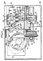
- - la figure 4 est une vue de droite, en coupe selon la figure IV-IV de la figure 3, de ce module d'affranchissement,
- - la figure 5 est une vue de dessus partiellement coupée de ce module d'affranchissement,
- - la figure 6 est un schéma-bloc du circuit de commande de la machine.
- FIG. 1 is an exploded perspective view illustrating the constitution of a machine according to the present invention,
- FIG. 2 shows an assembled machine, which results from FIG. 1,
- FIG. 3 represents one of the modules of the machine, known as a franking module, shown in cross section through a so-called front part of the module,
- FIG. 4 is a right view, in section according to FIG. IV-IV of FIG. 3, of this franking module,
- FIG. 5 is a partially cut away top view of this franking module,
- - Figure 6 is a block diagram of the machine control circuit.
La figure 1 montre la machine à affranchir miniature selon la présente invention elle est de préférence de constitution modulaire, mais peut tout aussi bien avoir ses éléments, qui correspondent à ses modules, faisant partie intégrante de la machine. La machine est décrite ci-après pour sa constitution modulaire. Dans la figure 2, ses modules sont montrés assemblés les uns aux autres.Figure 1 shows the miniature franking machine according to the present invention it is preferably of modular construction, but may as well have its elements, which correspond to its modules, forming an integral part of the machine. The machine is described below for its modular constitution. In Figure 2, its modules are shown assembled to each other.
En regard de la figure 1 et/ou de la figure 2, on voit que cette machine comporte, de l'avant à l'arrière, pour un utilisateur devant elle :
- un module d'impression dit également module d'affranchissement 1, sous forme d'un petit boîtier, à tête d'impression 10 montée amovible à l'intérieur du module dans sa partie avant et à connecteur mâle 1A au bas de sa face arrière 11 et à pastille de raccordement 11A sensiblement à mi-hauteur sur cette face 11,
- un module comptable 2, plat, de type carte à puce, à pastille de raccordement 2A intégrée sur l'une de ses faces pour la pastille de raccordement 11A du module d'affranchissement 1,
- un module pèse-lettre 3, relativement plat, à connecteur femelle 38 au bas de l'une de ses grandes faces et connecteur mâle 3A au bas de la grande face opposée,
- un module d'alimentation 4, sous forme d'un boîtier de même hauteur que les modules 1 et 3, équipé d'un connecteur femelle 4B au bas de l'une de ses faces.
With reference to FIG. 1 and / or to FIG. 2, it can be seen that this machine comprises, from front to rear, for a user in front of it:
a printing module also called franking module 1, in the form of a small box, with a
an
- a relatively flat letter-weighing
- A power supply module 4, in the form of a box of the same height as the
Ces modules sont assemblés les uns contre les autres en étant raccordés les uns aux autres. Dans la figure 1, les flèches 2F, 3F et 4F traduisent l'assemblage de chacun des modules 2, 3 et 4 sur celui qui le reçoit. Mis à part le module comptable 2, les modules pèse-lettre 3 et d'alimentation 4 ont leurs faces équipées de connecteurs mâles ou femelles, qui ont sensiblement les mêmes dimensions que la face arrière du module d'affranchissement 1. Les connecteurs mâles et femelles sur les faces des modules 1, 3 et 4 sont disposés à même niveau du bord inférieur de chaque module et sont complémentaires.These modules are assembled against each other by being connected to each other. In Figure 1, the
Le module d'affranchissement 1 présente sur sa face avant une fente 12 d'introduction d'un article dans le module 1. Une tirette 13 latérale, du côté de l'insertion de l'article dans la fente 12, lui est associée, pour un maintien de l'article. Ce module 1 est en outre équipé sur sa face supérieure inclinée, d'un écran de visualisation 14, à l'arrière, d'un clavier 15, et d'une trappe 16 d'accès à la tête d'impression 10, à l'avant. Une flèche 10F illustre le retrait possible de la tête 10 du module 1, en particulier pour son remplacement par une autre tête.The franking module 1 has on its front face a
Ce module d'affranchissement comporte dans sa partie intérieure, outre la tête 10, des moyens de déplacement de la tête et de l'article et un circuit de commande de la machine, décrits ci-après. On précise simplement en regard du circuit de commande, que celui-ci est formé de préférence sur deux cartes rapportées sur la paroi arrière et sur l'une des parois latérales du module 1, telles que la carte 17 schématisée dans la figure 1.This franking module comprises in its inner part, in addition to the
Le module pèse-lettre 3 est un module optionnel de la machine. Il permet avantageusement la mesure du poids avant l'affranchissement de chaque article, pour le calcul automatique du montant d'affranchissement de cet article par son propre circuit de commande ou celui de la machine auquel il est raccordé à travers les connecteurs 3B, 1A des modules 3 et 1. En l'absence d'un tel module pèse-lettre dans la machine, le montant d'affranchissement est rentré par le clavier.The
Ce module pèse-lettre 3 sous la forme d'un boîtier plat a une fente 3D verticale de réception de chaque article à peser, sur sa face supérieure. Le fond de la fente constitue un plateau de pesée 3P horizontal. Ce module est de type électronique, il permet une sélection entre différentes tranches de poids, 0-20 g, 20-50 g, 50-100 g, par exemple,pour chaque article, en vue du calcul du montant d'affranchissement correspondant à chaque tranche par son circuit de commande ou celui de la machine.This letter-weighing
Le module d'alimentation 4 est le module le plus arrière de la machine. Dans la figure 1, le module d'alimentation 4 présenté derrière le module pèse-lettre 3 est dit module secteur ; il est équipé de son cordon 4C à fiche terminale de raccordement sur une prise du secteur. Il comporte de manière connue des circuits transformateur, de redressement et de filtrage. Il est équipé d'un interrupteur 41 sur l'une de ses faces latérales.The power module 4 is the rearmost module of the machine. In FIG. 1, the power supply module 4 presented behind the letter-weighing
Dans la figure 1, on a fait apparaître en correspondance avec ce module d'alimentation secteur 4 d'une part un module d'alimentation à piles 4′ et d'autre part un module d'alimentation à batterie 4˝. L'un ou l'autre de ces modules 4′ et 4˝ peut être retenu à la place du module secteur 4, ainsi que traduit par les flèches 4′F et 4˝F qui leur correspondent. Ces modules 4′, 4˝ sont équipés, comme le module 4, d'un connecteur femelle 4′B ou 4˝B, selon le cas. Un chargeur de batterie 5, à cordon 5C avec fiche terminale de raccordement au secteur et équipé d'un connecteur mâle 5A pour le connecteur femelle 4˝B, est prévu pour le rechargement du module batterie 4˝, alors considéré retenu dans la machine.In Figure 1, there is shown in correspondence with this power supply module 4 on the one hand a battery power module 4 ′ and on the other hand a battery power module 4˝. One or the other of these modules 4 ′ and 4˝ can be retained in place of the sector module 4, as translated by the arrows 4′F and 4˝F which correspond to them. These modules 4 ′, 4˝ are equipped, like module 4, with a female connector 4′B or 4˝B, as the case may be. A battery charger 5, with
Le module comptable 2 à mémoire et microprosseur, du type carte à puce, est affecté aux transactions d'affranchissement de la machine, que cette machine soit utilisée en post-paiement ou en pré-paiement. En pré-paiement c'est de préférence une carte de crédit acquise par l'utilisateur, qui est débitée à chaque affranchissement du montant correspondant et permet de réaliser des affranchissements jusqu'à équisement du crédit disponible. En pré-paiement, elle peut être aussi une carte de chargement de fonds dans la machine. En post-paiement et, le cas échéant, en pré-paiement lorsque la machine a été précédemment rechargée en fonds, c'est, en outre, une carte d'identification de la machine et éventuellement de l'utilisateur.The
Ainsi qu'illustré également dans la figure 1, la machine comporte en outre, de manière optionnelle, un module mémoire 2′, également du type carte à puce, qui est extérieurement analogue au module comptable 2 et a sa pastille de raccordement 2′A et qui se raccorde en lieu et place du module comptable 2. Ce module mémoire 2′ est aussi dit carte d'enregistrement d'une flamme publicitaire. Une telle carte mémoire 2′, éditée par un service spécialisé à la demande de l'utilisateur, permet à l'utilisateur d'enregistrer la publicité, qui y est définie, dans sa machine.As also illustrated in FIG. 1, the machine further includes, optionally, a
En variante, l'utilisateur peut, au lieu d'acquérir une telle carte mémoire 2′, disposer d'un cordon 2C de connexion de la machine à un circuit extérieur, par exemple à un microordinateur, avec le programme convenable d'ordinateur, pour lui permettre de composer lui-même sa flamme publicitaire et les données de définition de cette flamme et d'enregistrer dans la machine ces données de définition de cette flamme publicitaire l'utilisateur peut également enregistrer des adresses de destinataires de ses plis de courrier, dans sa machine. Ce cordon de connexion 2C est à extrémité de connexion à la machine à affranchir se présentant sous forme d'un module de connexion 2˝ du type carte et extérieurement identique au module 2. Ce module de connexion 2˝ a sa pastille de raccordement repérée en 2˝A, et se raccorde en lieu et place du module 2 sur le module 1.As a variant, the user can, instead of acquiring such a
Dans la figure 1, la flèche 2′F ou la flèche 2˝F traduit l'utilisation optionnelle du module ou carte mémoire 2′ ou du module ou carte de connexion 2˝ à un microordinateur, pour l'enregistrement dans la machine de toute nouvelle flamme publicitaire et, le cas échéant, d'adresses.In FIG. 1, the
En outre dans la machine, le clavier 15 du module d'impression constitue aussi un moyen d'entrée de données alphanumériques pour l'enregistrement d'une flamme publicitaire dite alors simplifiée et d'adresses. Ce même clavier est, en outre, un moyen de sélection d'un mode opératoire de la machine parmi plusieurs modes opératoires possibles.In addition, in the machine, the
Dans les figures 3, 4 et 5, on a donné un exemple de réalisation du module d'affranchissement 1. Ce module qui est le plus volumineux dans la machine reste de très faibles dimensions et est de faible poids ; par exemple sa face arrière fait 100 x 105 mm, en hauteur et largeur, sa face inférieure ou supérieure a une longueur de l'ordre de 150 mm, son poids est inférieur au kilogramme.In FIGS. 3, 4 and 5, an exemplary embodiment of the franking module 1 has been given. This module which is the largest in the machine remains very small and is of low weight; for example its rear face is 100 x 105 mm, in height and width, its lower or upper face has a length of the order of 150 mm, its weight is less than a kilogram.
En se reportant à ces figures 3 à 5, on voit que la tête d'impression 10 est portée par un support 20. Elle est montée amovible et verrouillable sur son support par des moyens non représentés, en étant connectée à travers son support au circuit de commande monté dans ce module. Cette tête d'impression est en tant que telle connue. C'est un composant de petites dimensions, tel qu'une tête d'impression à jet d'encre ou à aiguilles. C'est de préférence une tête à jet d'encre telle que celle connue sous l'appellation THINK JET de la société HEWLETT PACKARD. Elle est a un nombre restreint de buses d'éjection d'encre, à faible pas entre elles et en une rangée sur une face dite base de la tête. Elle a un réservoir interne d'encre pour l'alimentation de ses buses.Referring to these Figures 3 to 5, we see that the
Un réseau d'éléments de commande est associé aux buses individuelles. Un réseau de liaisons de commande pour ce réseau d'éléments aboutit sur la base de la tête, d'un côté dit arrière de la rangée de buses. Il vient se raccorder sur le support portant la tête, d'où partent les liaisons allant vers le circuit de commande de la machine. Une telle tête d'impression à jet d'encre est à durée d'impression limitée et constitue un composant jetable que l'on remplace par une tête neuve identique, lorsque sa réserve interne d'encre est épuisée.A network of control elements is associated with the individual nozzles. A network of control links for this network of elements terminates on the base of the head, on a so-called rear side of the row of nozzles. It is connected to the support carrying the head, from where the connections go to the machine control circuit. Such an inkjet printhead has a limited printing time and constitutes a disposable component which is replaced by an identical new head, when its internal ink reserve is used up.
Pour cette tête à jet d'encre, montée verticale dans le module 1, on a simplement repéré sa base par la référence 10A et sa rangée de buses par la référence 10B. On précise en outre que la rangée de buses vient à l'avant du support 20 et s'étend parallèlement à la face avant du module 1, c'est-à-dire au plan de la figure 3 ; elle donne la direction de l'une des dimensions d'une zone à imprimer sur l'article, mais est de longueur inférieure à cette dimension.For this inkjet head, mounted vertically in module 1, its base has simply been identified by the
Dans la figure 3, en particulier, on voit que le support 20 de la tête est monté en coulisseau sur une tige horizontale 21. Il est également dit coulisseau. Il est, avec la tête 10 dans la partie avant du module 1, juste au dessus de la fente 12 d'introduction de l'article. Des moyens 22 d'actionnement du coulisseau, qui sont fixés sur lui, sont couplés à un moyen de commande 23, pour son déplacement d'avant vers l'arrière et inversement dans la machine, sur la tige 21.In Figure 3, in particular, we see that the support 20 of the head is slidably mounted on a
La fente 12 est définie entre deux plaques horizontales fixes, 25 et 26, s'étendant sous la tête, et distantes l'une de l'autre de l'épaisseur maximale des articles à introduire dans la machine. La plaque inférieure 25 est dite plaque d'introduction. La plaque supérieure 26 est dite plaque d'impression. Cette plaque d'impression est à faible distance de la rangée de buses 10B. Elle présente une fenêtre 26A au droit de la rangée de buses, à travers laquelle est réalisée l'impression d'un timbre d'affranchissement, de la vignette du bureau d'attache de la machine et, si souhaité d'une flamme publicitaire, sur l'article. La fenêtre est de largeur, apparaissant dans la figure 3, légèrement supérieure à la longueur de la rangée de buses sa longueur correspond à la hauteur des empreintes à imprimer, soit de l'ordre de 25 mm.The
La fente 12 a ses extrémités ouvertes sur les deux côtés latéraux du module d'affranchissement, dans sa partie avant. On a repéré en 12A son extrémité évasée d'entrée de chaque article et 12B son extrémité de sortie.The
Cette fente 12 est équipée de moyens 30 assurant l'avance et le maintien de l'article en position d'impression relativement à la tête et sa rangée de buses. Ces moyens 30 comportent, du côté de l'extrémité 12A d'entrée, un galet lisse 31 monté au dessus de la fente, et un galet 32, à gorges périphériques non référencées, monté au dessous de la fente. Un jeu de courroies sans fin 33, engagées dans les gorges et reçues sur un petit galet de renvoi 34 monté du côté de l'extrémité 12B, est tendu le long de la fente.This
Les galets 31 et 32 sont entraînés selon les flèches 31A et 32B et les courroies selon la flèche 33A, pour l'avance de l'article. Ces mêmes moyens 30 comportent en outre une paire de bras 35 articulés sur l'axe du galet 32 et portant entre eux le galet de renvoi 34. Cette paire de bras est sollicitée par des ressorts 36, pour entraîner le galet de renvoi à travers la fente, ainsi qu'illustré par la flèche 35A. Elle sollicite le jeu de courroies 33 contre la plaque d'impression 26 pour l'application de tout article, introduit dans l'extrémité 12A de la fente 12 et pris entre les galets 31 et 32 contre cette plaque d'impression, au cours de son avance le long de la fente.The
Le galet 31 affleure sur le côté supérieur de la fente 12 ; le galet 32 portant les courroies 33 est quant à lui sollicité par des ressorts 37 pour venir en pression contre le galet 31 à travers la fente, pour coopérer à une bonne application de tout article contre la plaque d'impression 26, quelle que soit l'épaisseur de cet article.The
Cette fente 12 est en outre équipée d'un capteur 40A, 40B d'entrée d'un article dans la fente, monté proche des galets 31 et 32, du côté de l'entrée 12A. Ce capteur assure la commande d'entraînement des galets 31 et 32, pour l'avance de l'article pour un cycle d'impression qu'il déclenche. La fente est équipée d'un autre capteur 41A, 41B, monté légèrement au-delà de la rangée de buses. Ce capteur 41A, 41B assure une détection de présence d'article dans une position d'impression sous la tête. Il déclenche une phase d'impression du cycle d'impression. Il déclenche aussi une phase d'éjection de l'article, après cette phase d'impression.This
Dans le module d'affranchissement, un troisième capteur 42A, 42B est monté pour détecter un drapeau 43 associé, qui est porte par le support ou coulisseau 20. Ce capteur 42A, 42B détectant le drapeau définit une position de référence d'impresion pour la commande d'impression et donc des jets d'encre au cours de la phase d'impression.In the franking module, a
Dans la figure 4 et/ou 5, on voit, en complément de la description ci-avant, que le galet 31 est maintenu entre deux paliers 44A, 44B et que le galet 32 est lui même maintenu entre deux paliers USA, 45B qui sont sollicités par les ressorts 37. Les paliers 44A, 44B pour le galet 31 constituent aussi le support de la tige 21 de guidage du coulisseau 20. Le palier 44A a en outre une échancrure 46 au niveau de la base de la tête 10. Cette échancrure est délimitée par la plaque d'introduction 25, formée directement ou rapportée sur ce palier 44A elle reçoit un bord de la plaque d'impression qui y est maintenue. Ces plaques 25 et 26 sont donc fixes en regard de la base de la tête montée sur le coulisseau. Le fond de l'échanchure 46, entre les plaques 25 et 26 définit le fond de la fente 12. Il est repéré par la référence 46A. Les deux capteurs montés le long de la fente 12, désignés simplement par référence 40, 41, sont au niveau du fond 46A de la fente 12 (figure 4).In FIG. 4 and / or 5, it can be seen, in addition to the description above, that the
Dans la figure 5, on a repéré par la flèche double 20A le déplacement du coulisseau 20 sur la tige de guidage 21, et on a illustré en traits pleins et en pointillés le coulisseau 20 et la tête 10 dans leurs deux positions extrêmes. Entre ces deux positions extrêmes la rangée de buses 18 se déplace sur une même trajectoire, alternativement dans un sens et l'autre. Le drapeau 43, solidaire du coulisseau 20 et associé au troisième capteur désigné simplement par la référence 42, présente avantageusement une fente 47 permettant de détecter l'un, et donc l'autre, des sens de déplacement de la rangée de buses.In FIG. 5, the displacement of the slide 20 on the
Les moyens 22 et 23 d'actionnement et de commande du coulisseau 20 sur la tige de guidage 21 et des moyens désignés globalement par la référence 50 d'entraînement des galets 31 et 32 sont décrits ci-après en se référant aux figures 4 et 5. Ces moyens sont couplés à un moteur commun 51, qui les commande. Ils sont logés avec le moteur 51 dans la partie arrière du module d'affranchissement 1, à l'arrière du coulisseau 20.The means 22 and 23 for actuating and controlling the slide 20 on the
A partir du moteur 51, un pignon moteur 52 assure l'entraînement d'un arbre de distribution 53 entraînant lui-même les moyens 23, 22 et les moyens 50. Cet arbre 53 porte à l'une de ses extrémités une roue 54, à denture intérieure continue 54A, sur laquelle est en prise le pignon moteur 52.From the
Une came montée au bas de l'arbre 53, à son autre extrémité et rendue solidaire de cet arbre constitue les moyens 23. La came porte cette référence 23. Elle a sa périphérie en forme de coeur, avec une pointe saillante 23A et une encoche 23B opposées.A cam mounted at the bottom of the
La roue 54 appartient quant à elle aux moyens 50. Elle présente à cet effet sur sa périphérie deux dents 54B opposées l'une à l'autre. Le choix de deux dents 54B résulte de la forme en coeur de la came 23. Ces dents sont l'une et l'autre en léger décalage par rapport à la pointe et à l'encoche de la came auxquelles elles correspondent respectivement lors de l'entraînement sur un tour de la came et de la roue. Ces moyens 50 comportent en outre des pignons 55 à 59 de couplage de la roue 54 avec les galets 31 et 32. Le pignon 55 est cylindrique, il vient sur la périphérie de la roue 54 en prise avec les deux dents 54B quand chacune des dents arrive à son niveau. Les pignons 56 et 57 forment un couple de pignons coniques entre l'arbre du pignon 55 et l'arbre du galet 31 transversaux qui les portent, respectivement, pour l'entraînement du galet 31. Le pignon 58, cylindrique, est monté sur l'arbre du galet 31 il est montré issu d'une seule pièce avec le pignon conique 57. Le pignon 59, également cylindrique, est monté sur l'arbre du galet 32 et vient en prise sur le pignon 58, il assure l'entraînement du galet 32, en synchronisme avec le galet 31 mais en sens inverse.The
Les moyens 22 couplent la came 23 et le coulisseau 20. Ils comportent un petit levier 60 articulé à une extrémité et à bec terminal coudé 60A, à l'oppose, en appui sur la périphérie, une biellette 61 d'entraînement du coulisseau 20 et un arbre vertical 62 de couplage entre le levier 60 et la biellette 61. Des ressorts 63 agissent sur l'arbre 62, pour solliciter le maintien du levier 60 en appui contre la périphérie de la came 23. Un doigt 20D sur le coulisseau 20 est retenu dans une lumière oblongue 61D de la biellette 61, pour la fixation de la biellette 61 sur le coulisseau (figure 5).The means 22 couple the
Pour chaque tour complet de rotation de l'arbre de distribution 53 entraînant la came, la biellette entraîne le coulisseau 20 le long de sa tige de guidage 21, dans un sens puis l'autre. La pointe 23A et l'encoche 23B donnent l'inversion du sens d'entraînement du coulisseau, avec une vitesse croissante à chaque début de course aller comme retour et une vitesse décroissante en fin de course aller comme retour. Les deux parties bombées opposées de la came, qui excluent les zones avec la pointe et l'encoche, sont définies pour donner une vitesse constante au coulisseau 20 ; elles définissent la partie utile, parcourue à vitesse constante, de la course aller et retour du coulisseau 20 sur la tige de guidage 21. L'impression de chaque empreinte est réalisée sur cette partie utile.For each complete rotation of the
Les moyens 50 assurent quant à eux l'entraînement des galets 31 et 32 et donc de l'article le long de la fente de la machine lorsque que le coulisseau 20 avec la tête 10 sont à l'arrêt ou pratiquement à l'arrêt.The means 50 in turn ensure the drive of the
Dans la figure 6, on a illustré sous forme de schéma-blocs le circuit de commande de la machine. Ce circuit de commande est logé dans le module d'impression 1. Il est désigné sous la référence globale 17 de la carte illustrée dans la figure 1. Il comporte :
- un ensemble de mémoires 70, dans lequel sont illustrées séparément des mémoires 71 à 74 précisées ci-après
- un microprocesseur 80, couplé aux mémoires de l'ensemble 70 selon les flèches indiquées
- des circuits d'interface 81 à 87 couplés d'une part au microprocesseur 80 et d'autre part aux éléments commandés ou de commande de la machine. Ces éléments de la machine sont l'écran d'affichage pour le circuit d'interface affichage 81, le clavier pour le circuit d'interface clavier 82, la tête d'impression pour le circuit d'interface tête 83, le moteur pour le circuit d'interface moteur 84, les trois capteurs pour le circuit d'interface capteurs 85, le module comptable pour le circuit d'interface financier 86 et le module mémoire ou le circuit extérieur de définition des données de flamme publicitaire pour le circuit d'interface de publicité 87. Les références de ces éléments décrits en regard des figures précédentes sont rappelées entre parenthèses sur les liaisons qu'ils ont avec les circuits d'interface, avec des flèches traduisant le sens du couplage, dans cette figure 6.In FIG. 6, the machine control circuit has been illustrated in the form of a block diagram. This control circuit is housed in the printing module 1. It is designated under the
a set of
- a
-
Dans l'ensemble de mémoires 70, la mémoire 71 est dite mémoire des compteurs financiers et des opérations d'affranchissement de la machine. La mémoire 72 constitue quant à elle une source de données de définition matricielle des empreintes du timbre d'affranchissement et de la vignette du bureau d'attache de la machine, sans leurs données variables de valeur et de date dans ces empreintes. La mémoire 73 constitue une source de données de définition de flamme publicitaire. La mémoire 74 constitue une source pour d'autres données fixes en particulier des données de définition d'adresses de l'expéditeur et de destinataires des plis de courrier.In the set of
De préférence les circuits d'interface financier et de publicité 86 et 87 sont portes par une première carte de commande montée dans le module d'affranchissement sur sa paroi arrière les autres circuits d'interface, le microprocesseur et l'ensemble de mémoires sont sur la deuxième carte de commande 17 montée également dans le module d'affranchissement mais sur l'une de ses parois latérales.Preferably, the financial and
La machine à affranchir miniature selon la présente invention présente plusieurs modes opératoires possibles. La sélection de l'un des modes opératoires est assurée par le clavier 15 (figures 1, 2). Ces différents modes opératoires sont en particulier :
- un mode opératoire en affranchissement, qui est le mode opératoire principal et normal d'utilisation de la machine, pour lequel la tête 10 imprime le timbre d'affranchissement au montant convenable, la vignette du bureau d'attache à la date du jour et éventuellement, la flamme publicitaire, dans une zone correspondante de dimensions définies sur les articles ou des étiquettes à opposer sur les articles, introduits successivement dans la machine;
- un mode opératoire en édition d'un bordereau comptable, pour lequel la tête 10 imprime les états des compteurs de la machine, issus de la mémoire 71, à la dernière édition réalisée et à l'instant de l'édition actuelle, avec éventuellement les opératoires financières individuelles entre cette dernière édition et celle actuelle, sur une ou plusieurs feuilles successives ou sur une ou plusieurs étiquettes successives introduites dans la machine ;
- un mode opératoire en adressage d'articles, pour lequel la tête 10 imprime l'adresse de l'expéditeur ou du destinataire de l'article concerné, issue de la mémoire 74 et également sélectionnée à partir du clavier, sur cet article ou une étiquette à apposer sur l'article, introduit dans la machine ;
- un mode opératoire en enregistrement de flammes publicitaires, pour lequel la machine enregistre dans sa mémoire 73 les données de définition de la flamme publicitaire à imprimer ;
- un mode opératoire en enregistrement d'adresses, pour lequel la machine enregistre dans sa mémoire 74 les données de définition d'adresses à imprimer.The miniature franking machine according to the present invention has several possible operating modes. The selection of one of the operating modes is ensured by the keyboard 15 (FIGS. 1, 2). These different operating modes are in particular:
- a franking operating mode, which is the main and normal operating mode of use of the machine, for which the
- a procedure for editing an accounting slip, for which the
- a procedure for addressing articles, for which the
- a procedure for recording advertising flames, for which the machine stores in its memory 73 the definition data of the advertising flame to be printed;
- an operating mode in address registration, for which the machine stores in its
Ces deux derniers modes opératoires en enregistrement, sélectionnés comme les autres modes opératoires par le clavier, consistent en un simple transfert de données, depuis le module 2′ ou le clavier 15, ou à travers le module 2˝, alors connecté au module d'affranchissement 1, vers la mémoire 73 ou 74 concernée. La procédure de transfert avec les modules 2′ et 2˝ est livrée avec les modules 2′, 2˝. Celle avec le clavier est intégrée dans le circuit de commande 17 sous forme d'une unité de traitement appropriée, non représentée, qui élabore les données ordonnées à enregistrer en réponse aux données alphanumériques entrées, en vue de leur impression ultérieure.These last two recording operating modes, selected like the other operating modes by the keyboard, consist of a simple data transfer, from
Les modes opératoires en affranchissement, en édition de bordereau et en adressage conduisent à des opérations d'impression réalisée par la tête, qui sont plus spécifiques de la machine selon l'invention. Chaque opération d'impression est effectuée en un cycle d'impression. Ce cycle d'impression se déroule d'une manière analogue quel que soit le mode opératoire concerné. Il est décrit ci-après en se référant aux figures, pour l'opération d'affranchissement d'un article, à laquelle est liée à une étape préliminaire supplémentaire pour définir le montant d'affranchissement.The methods of franking, edition of slip and addressing lead to printing operations performed by the head, which are more specific to the machine according to the invention. Each printing operation is performed in one printing cycle. This printing cycle takes place in an analogous manner regardless of the operating mode concerned. It is described below with reference to the figures, for the franking operation of an article, which is linked to an additional preliminary step to define the amount of franking.
Dans une machine équipée d'un module pèse-lettre 3, cette étape préliminaire consiste en la simple introduction de l'article dans la fente 3D du module pèse-lettre, donnant lieu au calcul automatique du montant d'affranchissement par la machine, avec l'affichage du montant sur l'écran, puis en la validation par le clavier du montant affiché. Dans la machine non équipée de module pèse-lettre, cette étape préliminaire consiste à rentrer le montant d'affranchissement directement par le clavier, la saisie de ce montant donnant lieu à son affichage à l'écran, puis à valider le montant affiché, par le clavier.In a machine equipped with a letter-weighing
Le cycle d'impression est exécuté sous le contrôle du microprecesseur, à partir de l'introduction de l'article à affranchir dans la fente 12 de la machine. Il est déclenché par le capteur 40 dès qu'il détecte la présence de l'article dans l'entrée de la fente 12. Il se décompose en une phase d'amenée de l'article en position d'impression, une phase d'impression et une phase d'éjection de l'article.The printing cycle is executed under the control of the microprocessor, from the introduction of the article to be franked in the
Pour ces trois phases, le moteur 51 est commande et entraîne l'arbre de distribution 53. Pour chaque demi-tour de rotation de cet arbre 53, l'une des dents 54B de la roue 54 vient en prise sur le pignon 55 et la came 23 fait un demi-tour. Il en résulte une avance, d'un pas, de l'article, puis un déplacement du coulisseau 20 et de la tête 10 dans un premier sens le long de la tige de guidage 21.For these three phases, the
Pour le demi-tour de rotation suivant de cet arbre 53, l'autre dent 54B de la roue 54 vient en prise sur le pignon 55 et la came 23 fait un autre demi-tour dans le même. Il en résulte une avance, du même pas et dans le même sens de l'article, puis un déplacement du coulisseau 20 et de la tête 10 dans l'autre sens le long de la tige de guidage. Pour ces trois phases, l'arbre de distribution 53 définit par tour complet de rotation une même séquence répétitive, d'avance de l'article de 2 pas et de déplacement de la tête sur une même course parcourue dans un sens après le premier des deux pas et dans l'autre après l'autre pas. Chaque pas d'avance de l'article fait selon la rangée de buses est égal à la longueur de la rangée de buses. Le déplacement de la tête est transversal à la rangée de buses donc à la direction d'avance de l'article.For the following half-turn of rotation of this
La phase d'amenée de l'article en position d'imprèssion et la phase d'éjection sont assurées par la seule commande du moteur 51. Le capteur 41 définit la fin de la phase d'amenée de l'article en position d'impression. Dans cette position d'impression l'article largement engagé dans la fente 12 est sous la tête d'impression 10 il est dès lors bien plaqué contre la plaque d'impression 26 et le restera pendant toute la phase d'impression.The phase of bringing the article into the printing position and the ejection phase are ensured by the sole control of the
La phase d'impression est exécutée, dès que le capteur 41 a détecté la présence de l'article, sous le contrôle du capteur 42 détectant le drapeau 43 et sa fente 47. La commande d'impression est initialisée par le capteur 42. Cette impression est réalisée sur la seule partie utilie de la course aller et retour de la tête qui est parcourue à vitesse constante. La course aller et retour de la tête et l'avance par pas de l'article conduisent à un balayage, par lignes contigues, des zones d'impression du timbre, de la vignette du bureau d'attache et de la flamme publicitaire sur l'article, fait successivement et selon la hauteur des zones. Les données de définition du timbre et de la vignette du bureau d'attache, issues de la source 72, auxquelles sont mixées convenablement les données variables du montant de l'affranchissement, rentrées par le clavier ou calculées automatiquement, et de la date, issues d'une horloge interne non représentée, puis éventuellement les données de définition de la flamme publicitaire, commandent l'impression des lignes contigues de chacune de ces zones balayées l'une après l'autre.The printing phase is executed, as soon as the
Le nombre de lignes balayées, depuis le début d'impression, est également détecté à partir du capteur 42. Ce nombre permet au microprocesseur de contrôler la fin d'impression du timbre, de la vignette du bureau d'attache et de la flamme publicitaire.The number of lines scanned, since the start of printing, is also detected from
La fin de cette phase d'impression est donnée par un nombre défini de lignes balayées pendant ce cycle d'impression, pour chaque mode opératoire ce nombre ne peut pas excéder un nombre maximal donné. Elle donne lieu à la phase d'éjection de l'article. La fin de cette phase d'éjection est donnée par le capteur 41 après le passage de l'article sous ce capteur. Le capteur 41 commande l'arrêt du moteur 51.The end of this printing phase is given by a defined number of lines scanned during this printing cycle, for each operating mode this number cannot exceed a given maximum number. It gives rise to the article ejection phase. The end of this ejection phase is given by the
L'opération d'édition d'un bordereau et l'opération d'adressage sont analogues à celle d'affranchissement. On précise simplement que, pour l'édition d'un bordereau nécessitant plusieurs feuilles, l'impression de chaque feuille s'arrête après 30 lignes d'impression auxquelles correspond le nombre maximal de lignes balayées par la tête pendant le phase d'impression. L'écran d'affichage sera rendu clignotant pour signalier la demande d'une autre feuille. En regard de l'adressage de lettres, on précise que chaque lettre est introduite dans la fente de la machine par son verso, pour l'impression de l'adresse de l'expéditeur ; la lettre est par contre introduite dans la fente de la machine par son recto avec son pied venant contre le fond de la fente, pour l'impression de l'adresse du destinataire. Bien entendu la machine peut recevoir des étiquettes, ou cartes sur lesquelles elle imprime l'adresse souhaitée.The operation of editing a slip and the addressing operation are similar to that of franking. It is simply specified that, for the edition of a slip requiring several sheets, the printing of each sheet stops after 30 printing lines to which corresponds the maximum number of lines scanned by the head during the printing phase. The display screen will be made flashing to indicate the request for another sheet. With regard to the addressing of letters, it is specified that each letter is introduced into the slot of the machine by its back, for printing the address of the sender; the letter is on the other hand introduced into the slot of the machine by its front with its foot coming against the bottom of the slot, for the printing of the address of the recipient. Of course the machine can receive labels, or cards on which it prints the desired address.
La machine selon l'invention, de part sa construction modulaire possible, est avantageusement rendue adaptable aux besoins de chaque utilisateur. Elle est de prix faible et avec sa tête d'impression à jet d'encre jetable et directement remplaçable quand la réserve d'encre est épuisée.The machine according to the invention, due to its possible modular construction, is advantageously made adaptable to the needs of each user. It is inexpensive and with its disposable inkjet printhead and directly replaceable when the ink supply is used up.
Elle est de fonctionnement simple et sûr, avec plusieurs modes opératoires possibles sélectionnés à la demande par l'utilisateur.It is simple and safe to operate, with several possible operating modes selected at the request of the user.
Dans la machine selon l'invention, son module d'impression a été décrit en regard de l'exemple de réalisation illustré. Il est évident que l'on peut y apporter des modifications de détail et/ou remplacer certains moyens par d'autres équivalents. En particulier on peut utiliser deux moteurs distincts pour l'avance de l'article et pour le déplacement de la tête, on peut aussi utiliser des systèmes à pignons, au lieu de la came en forme de coeur, pour le déplacement alternatif dans un sens et l'autre de la tête d'impression à partir de l'arbre de distribution précité.In the machine according to the invention, its printing module has been described with reference to the illustrated embodiment. It is obvious that one can make detailed modifications to it and / or replace certain means by other equivalents. In particular one can use two distinct motors for the advance of the article and for the displacement of the head, one can also use systems with pinions, instead of the cam in the shape of heart, for the reciprocating displacement in one direction and the other from the print head from the aforementioned distribution shaft.
Claims (31)
- ladite source (70) comporte au moins une première source (72) affectée à la définition matricielle d'un timbre d'affranchissement et d'une vignette du bureau d'attache de la machine, pour une zone d'impression de dimensions transversales définies,
- ladite tête (10) est à nombre limité d'éléments d'impression, dont la rangée donne la direction de l'une des dimensions de la zone mais est de longueur inférieure à cette dimension,
- lesdits moyens de déplacement comportent des premiers moyens (30) de déplacement de l'article selon la rangée d'éléments et des deuxièmes moyens (20-22) de déplacement de la tête transversalement à la rangée d'éléments, et
- lesdits moyens de commande (17) sont à microprocesseur et définissent un cycle d'impression, déclenché et contrôlé par lesdits moyens de détection (40-42), pendant lequel l'article avance par pas égal à la longueur de la rangée d'éléments et la tête se déplace, entre chaque pas, alternativement dans un sens après l'un des pas et dans l'autre sens après le pas suivant, et au cours duquel la zone est imprimée sur l'article avec le balayage de lignes successives sur la zone pendant une phase dite d'impression puis l'article est éjecté, sans impression, pendant une phase dite d'éjection.1 / Miniature franking machine, comprising a printing head with unitary printing elements in a row on a face known as the base of the head, means for relative movement of the head on the article, means for detecting the article relative to the head, a data source to be printed coupled to the head and control means for printing the data, characterized in that:
- Said source (70) comprises at least a first source (72) assigned to the matrix definition of a franking stamp and of a sticker of the home office of the machine, for a printing area of transverse dimensions defined,
said head (10) has a limited number of printing elements, the row of which gives the direction of one of the dimensions of the area but is of length less than this dimension,
said displacement means comprise first means (30) for displacing the article along the row of elements and second means (20-22) for displacing the head transversely to the row of elements, and
- Said control means (17) are microprocessor-based and define a printing cycle, triggered and controlled by said detection means (40-42), during which the article advances in steps equal to the length of the row of elements and the head moves, between each step, alternately in one direction after one of the steps and in the other direction after the next step, and during which the zone is printed on the article with the scanning of successive lines on the area during a so-called printing phase then the article is ejected, without printing, during a so-called ejection phase.
Applications Claiming Priority (2)
| Application Number | Priority Date | Filing Date | Title |
|---|---|---|---|
| FR8908826 | 1989-06-30 | ||
| FR8908826A FR2649230B1 (en) | 1989-06-30 | 1989-06-30 | MINIATURE POSTAGE MACHINE |
Publications (2)
| Publication Number | Publication Date |
|---|---|
| EP0405357A1 true EP0405357A1 (en) | 1991-01-02 |
| EP0405357B1 EP0405357B1 (en) | 1994-11-02 |
Family
ID=9383354
Family Applications (1)
| Application Number | Title | Priority Date | Filing Date |
|---|---|---|---|
| EP19900111868 Expired - Lifetime EP0405357B1 (en) | 1989-06-30 | 1990-06-22 | Miniature franking machine |
Country Status (3)
| Country | Link |
|---|---|
| EP (1) | EP0405357B1 (en) |
| DE (1) | DE69013769T2 (en) |
| FR (1) | FR2649230B1 (en) |
Cited By (7)
| Publication number | Priority date | Publication date | Assignee | Title |
|---|---|---|---|---|
| EP0550225A2 (en) * | 1991-12-30 | 1993-07-07 | Neopost Limited | Franking machine |
| EP0566225A2 (en) * | 1992-04-16 | 1993-10-20 | Francotyp-Postalia GmbH | Method for data input in a franking machine, assembly for franking mail and for producing a mail image respectively related to the mailing office |
| EP0658861A1 (en) * | 1993-12-16 | 1995-06-21 | Francotyp-Postalia GmbH | Method for operating a franking machine |
| US5490077A (en) * | 1993-01-20 | 1996-02-06 | Francotyp-Postalia Gmbh | Method for data input into a postage meter machine, arrangement for franking postal matter and for producing an advert mark respectively allocated to a cost allocation account |
| US5606508A (en) * | 1992-04-16 | 1997-02-25 | Francotyp Postalia Gmbh | Assembly for franking postal matter |
| US5699258A (en) * | 1992-04-16 | 1997-12-16 | Francotyp-Postalia Ag & Co | Assembly for franking postal matter, and multi-carrier shipping system |
| EP1615177A1 (en) * | 2004-07-08 | 2006-01-11 | Neopost Industrie | Electronic franking stamp |
Families Citing this family (2)
| Publication number | Priority date | Publication date | Assignee | Title |
|---|---|---|---|---|
| DE10114529A1 (en) | 2001-03-21 | 2002-10-02 | Francotyp Postalia Ag | Franking machine with retrofittable weighing device |
| DE102006022210A1 (en) * | 2006-05-11 | 2007-11-15 | Francotyp-Postalia Gmbh | Arrangement and method for creating a franking imprint |
Citations (9)
| Publication number | Priority date | Publication date | Assignee | Title |
|---|---|---|---|---|
| BE850225R (en) * | 1977-01-07 | 1977-07-07 | Photronic Internat Establishme | COMBINED POSTAL MACHINE |
| GB2142876A (en) * | 1983-07-08 | 1985-01-30 | Telefonia Automazione Elettron | Stamping set |
| GB2188878A (en) * | 1986-04-10 | 1987-10-14 | Pitney Bowes Inc | Postage meter message printing system |
| FR2603408A1 (en) * | 1986-09-02 | 1988-03-04 | Pitney Bowes Inc | SECURITY PRINTER FOR PRINTING VALUES |
| WO1988001818A1 (en) * | 1986-09-02 | 1988-03-10 | Wright Christopher B | Automated transaction system using microprocessor cards |
| US4787311A (en) * | 1987-08-19 | 1988-11-29 | Pitney Bowes Inc. | Mailing machine envelope transport system |
| GB2206082A (en) * | 1987-06-17 | 1988-12-29 | Alcatel Business Systems | Franking machine incorporating ink-jet printer and microprocessor for accounting and control |
| EP0298775A2 (en) * | 1987-07-09 | 1989-01-11 | Neopost Limited | Franking machine |
| US4809015A (en) * | 1988-03-14 | 1989-02-28 | Eastman Kodak Company | Continuous ink jet printer having modular print head assembly |
-
1989
- 1989-06-30 FR FR8908826A patent/FR2649230B1/en not_active Expired - Fee Related
-
1990
- 1990-06-22 EP EP19900111868 patent/EP0405357B1/en not_active Expired - Lifetime
- 1990-06-22 DE DE1990613769 patent/DE69013769T2/en not_active Expired - Fee Related
Patent Citations (9)
| Publication number | Priority date | Publication date | Assignee | Title |
|---|---|---|---|---|
| BE850225R (en) * | 1977-01-07 | 1977-07-07 | Photronic Internat Establishme | COMBINED POSTAL MACHINE |
| GB2142876A (en) * | 1983-07-08 | 1985-01-30 | Telefonia Automazione Elettron | Stamping set |
| GB2188878A (en) * | 1986-04-10 | 1987-10-14 | Pitney Bowes Inc | Postage meter message printing system |
| FR2603408A1 (en) * | 1986-09-02 | 1988-03-04 | Pitney Bowes Inc | SECURITY PRINTER FOR PRINTING VALUES |
| WO1988001818A1 (en) * | 1986-09-02 | 1988-03-10 | Wright Christopher B | Automated transaction system using microprocessor cards |
| GB2206082A (en) * | 1987-06-17 | 1988-12-29 | Alcatel Business Systems | Franking machine incorporating ink-jet printer and microprocessor for accounting and control |
| EP0298775A2 (en) * | 1987-07-09 | 1989-01-11 | Neopost Limited | Franking machine |
| US4787311A (en) * | 1987-08-19 | 1988-11-29 | Pitney Bowes Inc. | Mailing machine envelope transport system |
| US4809015A (en) * | 1988-03-14 | 1989-02-28 | Eastman Kodak Company | Continuous ink jet printer having modular print head assembly |
Cited By (13)
| Publication number | Priority date | Publication date | Assignee | Title |
|---|---|---|---|---|
| EP0550225A3 (en) * | 1991-12-30 | 1995-04-19 | Neopost Ltd | Franking machine |
| EP0550225A2 (en) * | 1991-12-30 | 1993-07-07 | Neopost Limited | Franking machine |
| EP0911767A2 (en) * | 1992-04-16 | 1999-04-28 | Francotyp-Postalia Aktiengesellschaft & Co. | Method for data entry in a franking machine and apparatus for for franking mail |
| EP0566225A3 (en) * | 1992-04-16 | 1995-04-05 | Francotyp Postalia Gmbh | Method for data input in a franking machine, assembly for franking mail and for producing a mail image respectively related to the mailing office. |
| US5606508A (en) * | 1992-04-16 | 1997-02-25 | Francotyp Postalia Gmbh | Assembly for franking postal matter |
| US5699258A (en) * | 1992-04-16 | 1997-12-16 | Francotyp-Postalia Ag & Co | Assembly for franking postal matter, and multi-carrier shipping system |
| EP0566225A2 (en) * | 1992-04-16 | 1993-10-20 | Francotyp-Postalia GmbH | Method for data input in a franking machine, assembly for franking mail and for producing a mail image respectively related to the mailing office |
| EP0911767A3 (en) * | 1992-04-16 | 2000-09-27 | Francotyp-Postalia Aktiengesellschaft & Co. | Method for data entry in a franking machine and apparatus for for franking mail |
| US5490077A (en) * | 1993-01-20 | 1996-02-06 | Francotyp-Postalia Gmbh | Method for data input into a postage meter machine, arrangement for franking postal matter and for producing an advert mark respectively allocated to a cost allocation account |
| US5602743A (en) * | 1993-01-20 | 1997-02-11 | Francotyp-Postalia Ag & Co. | Method for data input into a postage meter machine, arrangement for franking postal matter and for producing a franking design respectively allocated to a cost center |
| EP0658861A1 (en) * | 1993-12-16 | 1995-06-21 | Francotyp-Postalia GmbH | Method for operating a franking machine |
| EP1615177A1 (en) * | 2004-07-08 | 2006-01-11 | Neopost Industrie | Electronic franking stamp |
| FR2872947A1 (en) * | 2004-07-08 | 2006-01-13 | Neopost Ind Sa | BUFFER WITH ELECTRONIC AFFRANCHIR |
Also Published As
| Publication number | Publication date |
|---|---|
| EP0405357B1 (en) | 1994-11-02 |
| DE69013769D1 (en) | 1994-12-08 |
| FR2649230B1 (en) | 1993-11-26 |
| DE69013769T2 (en) | 1995-03-09 |
| FR2649230A1 (en) | 1991-01-04 |
Similar Documents
| Publication | Publication Date | Title |
|---|---|---|
| EP0405357B1 (en) | Miniature franking machine | |
| EP0589755A1 (en) | Game terminal | |
| EP0405356B1 (en) | Office machine for expediting postal articles | |
| FR2649022A1 (en) | METHOD FOR ENCODING CORRESPONDENCE AND DEVICE FOR IMPLEMENTING SAID METHOD | |
| EP0191678B1 (en) | Device for processing documents, in particular cheques | |
| EP0453974A2 (en) | Controlling the print and cut quality in a machine for the production of packagings | |
| CH677982A5 (en) | ||
| EP1224082B1 (en) | Printing module for two printing substrates and distributors equipped with modules of this type | |
| EP0978105B1 (en) | Franking and addressing device | |
| EP1024461B1 (en) | Autonomous and multifunctional system for the preparation of mail | |
| EP0495070B1 (en) | Automatic equipment for the continuous composition and printing of short texts | |
| FR2727547A1 (en) | DEVICE FOR DETECTING MALFUNCTION OF AN INK JET PRINTHEAD OF A POSTAGE MACHINE | |
| FR2624796A1 (en) | RELEASE MECHANISM OF A PRINTING WHEEL STOPPER | |
| EP1193655A1 (en) | Multi-purpose franking machine | |
| FR2478850A1 (en) | CASH TICKET DISTRIBUTOR DEVICE FOR RECORDING PRICE OF GOODS, SUCH AS PRICE CALCULATOR BALANCE WITH PRINTER | |
| EP0405358B1 (en) | Letter scales for a franking machine and resulting franking machine | |
| CH680540A5 (en) | ||
| FR2493230A1 (en) | APPARATUS FOR WRITING CHECKS | |
| CH678161A5 (en) | ||
| EP0855683A1 (en) | Compact mailing machine with special transport path | |
| EP0604296B1 (en) | Electronic franking machine with two printing drums for fixed and variable data | |
| CH679345A5 (en) | ||
| FR2862564A1 (en) | PRINTING METHOD FOR COMPACT MACHINE AND ASSOCIATED MACHINE | |
| EP1396823A2 (en) | Domestic gas bottle dispensing system | |
| LU85436A1 (en) | ELECTRONIC PRINTING MACHINE |
Legal Events
| Date | Code | Title | Description |
|---|---|---|---|
| PUAI | Public reference made under article 153(3) epc to a published international application that has entered the european phase |
Free format text: ORIGINAL CODE: 0009012 |
|
| AK | Designated contracting states |
Kind code of ref document: A1 Designated state(s): DE FR GB |
|
| 17P | Request for examination filed |
Effective date: 19910624 |
|
| RAP1 | Party data changed (applicant data changed or rights of an application transferred) |
Owner name: NEOPOST INDUSTRIE |
|
| 17Q | First examination report despatched |
Effective date: 19930917 |
|
| GRAA | (expected) grant |
Free format text: ORIGINAL CODE: 0009210 |
|
| AK | Designated contracting states |
Kind code of ref document: B1 Designated state(s): DE FR GB |
|
| REF | Corresponds to: |
Ref document number: 69013769 Country of ref document: DE Date of ref document: 19941208 |
|
| GBT | Gb: translation of ep patent filed (gb section 77(6)(a)/1977) |
Effective date: 19941122 |
|
| PLBI | Opposition filed |
Free format text: ORIGINAL CODE: 0009260 |
|
| 26 | Opposition filed |
Opponent name: PITNEY BOWES, INC. Effective date: 19950801 |
|
| PLBF | Reply of patent proprietor to notice(s) of opposition |
Free format text: ORIGINAL CODE: EPIDOS OBSO |
|
| PLBO | Opposition rejected |
Free format text: ORIGINAL CODE: EPIDOS REJO |
|
| PLBN | Opposition rejected |
Free format text: ORIGINAL CODE: 0009273 |
|
| STAA | Information on the status of an ep patent application or granted ep patent |
Free format text: STATUS: OPPOSITION REJECTED |
|
| 27O | Opposition rejected |
Effective date: 19961130 |
|
| REG | Reference to a national code |
Ref country code: GB Ref legal event code: IF02 |
|
| PGFP | Annual fee paid to national office [announced via postgrant information from national office to epo] |
Ref country code: DE Payment date: 20080620 Year of fee payment: 19 |
|
| PGFP | Annual fee paid to national office [announced via postgrant information from national office to epo] |
Ref country code: FR Payment date: 20080613 Year of fee payment: 19 |
|
| PGFP | Annual fee paid to national office [announced via postgrant information from national office to epo] |
Ref country code: GB Payment date: 20080620 Year of fee payment: 19 |
|
| GBPC | Gb: european patent ceased through non-payment of renewal fee |
Effective date: 20090622 |
|
| REG | Reference to a national code |
Ref country code: FR Ref legal event code: ST Effective date: 20100226 |
|
| PG25 | Lapsed in a contracting state [announced via postgrant information from national office to epo] |
Ref country code: FR Free format text: LAPSE BECAUSE OF NON-PAYMENT OF DUE FEES Effective date: 20090630 |
|
| PG25 | Lapsed in a contracting state [announced via postgrant information from national office to epo] |
Ref country code: GB Free format text: LAPSE BECAUSE OF NON-PAYMENT OF DUE FEES Effective date: 20090622 |
|
| PG25 | Lapsed in a contracting state [announced via postgrant information from national office to epo] |
Ref country code: DE Free format text: LAPSE BECAUSE OF NON-PAYMENT OF DUE FEES Effective date: 20100101 |