EP0414900A1 - Rotierende kodiervorrichtung - Google Patents
Rotierende kodiervorrichtung Download PDFInfo
- Publication number
- EP0414900A1 EP0414900A1 EP89911887A EP89911887A EP0414900A1 EP 0414900 A1 EP0414900 A1 EP 0414900A1 EP 89911887 A EP89911887 A EP 89911887A EP 89911887 A EP89911887 A EP 89911887A EP 0414900 A1 EP0414900 A1 EP 0414900A1
- Authority
- EP
- European Patent Office
- Prior art keywords
- light
- plate
- pulse plate
- reflective
- pulse
- Prior art date
- Legal status (The legal status is an assumption and is not a legal conclusion. Google has not performed a legal analysis and makes no representation as to the accuracy of the status listed.)
- Granted
Links
- XEEYBQQBJWHFJM-UHFFFAOYSA-N Iron Chemical compound [Fe] XEEYBQQBJWHFJM-UHFFFAOYSA-N 0.000 claims abstract description 13
- 229910052742 iron Inorganic materials 0.000 claims abstract description 6
- 230000003287 optical effect Effects 0.000 claims description 29
- 239000000463 material Substances 0.000 claims description 8
- 230000035807 sensation Effects 0.000 description 23
- 239000000758 substrate Substances 0.000 description 9
- 238000010586 diagram Methods 0.000 description 6
- 230000007274 generation of a signal involved in cell-cell signaling Effects 0.000 description 4
- 229910001229 Pot metal Inorganic materials 0.000 description 3
- 239000004020 conductor Substances 0.000 description 3
- 230000006866 deterioration Effects 0.000 description 2
- 230000000712 assembly Effects 0.000 description 1
- 238000000429 assembly Methods 0.000 description 1
- 230000003247 decreasing effect Effects 0.000 description 1
- 239000011810 insulating material Substances 0.000 description 1
- 238000004519 manufacturing process Methods 0.000 description 1
- 239000002184 metal Substances 0.000 description 1
- 229910052751 metal Inorganic materials 0.000 description 1
Images


Classifications
-
- G—PHYSICS
- G01—MEASURING; TESTING
- G01D—MEASURING NOT SPECIALLY ADAPTED FOR A SPECIFIC VARIABLE; ARRANGEMENTS FOR MEASURING TWO OR MORE VARIABLES NOT COVERED IN A SINGLE OTHER SUBCLASS; TARIFF METERING APPARATUS; MEASURING OR TESTING NOT OTHERWISE PROVIDED FOR
- G01D5/00—Mechanical means for transferring the output of a sensing member; Means for converting the output of a sensing member to another variable where the form or nature of the sensing member does not constrain the means for converting; Transducers not specially adapted for a specific variable
- G01D5/26—Mechanical means for transferring the output of a sensing member; Means for converting the output of a sensing member to another variable where the form or nature of the sensing member does not constrain the means for converting; Transducers not specially adapted for a specific variable characterised by optical transfer means, i.e. using infrared, visible, or ultraviolet light
- G01D5/28—Mechanical means for transferring the output of a sensing member; Means for converting the output of a sensing member to another variable where the form or nature of the sensing member does not constrain the means for converting; Transducers not specially adapted for a specific variable characterised by optical transfer means, i.e. using infrared, visible, or ultraviolet light with deflection of beams of light, e.g. for direct optical indication
- G01D5/30—Mechanical means for transferring the output of a sensing member; Means for converting the output of a sensing member to another variable where the form or nature of the sensing member does not constrain the means for converting; Transducers not specially adapted for a specific variable characterised by optical transfer means, i.e. using infrared, visible, or ultraviolet light with deflection of beams of light, e.g. for direct optical indication the beams of light being detected by photocells
-
- H—ELECTRICITY
- H01—ELECTRIC ELEMENTS
- H01H—ELECTRIC SWITCHES; RELAYS; SELECTORS; EMERGENCY PROTECTIVE DEVICES
- H01H5/00—Snap-action arrangements, i.e. in which during a single opening operation or a single closing operation energy is first stored and then released to produce or assist the contact movement
- H01H5/02—Energy stored by the attraction or repulsion of magnetic parts
-
- G—PHYSICS
- G01—MEASURING; TESTING
- G01D—MEASURING NOT SPECIALLY ADAPTED FOR A SPECIFIC VARIABLE; ARRANGEMENTS FOR MEASURING TWO OR MORE VARIABLES NOT COVERED IN A SINGLE OTHER SUBCLASS; TARIFF METERING APPARATUS; MEASURING OR TESTING NOT OTHERWISE PROVIDED FOR
- G01D5/00—Mechanical means for transferring the output of a sensing member; Means for converting the output of a sensing member to another variable where the form or nature of the sensing member does not constrain the means for converting; Transducers not specially adapted for a specific variable
- G01D5/26—Mechanical means for transferring the output of a sensing member; Means for converting the output of a sensing member to another variable where the form or nature of the sensing member does not constrain the means for converting; Transducers not specially adapted for a specific variable characterised by optical transfer means, i.e. using infrared, visible, or ultraviolet light
- G01D5/32—Mechanical means for transferring the output of a sensing member; Means for converting the output of a sensing member to another variable where the form or nature of the sensing member does not constrain the means for converting; Transducers not specially adapted for a specific variable characterised by optical transfer means, i.e. using infrared, visible, or ultraviolet light with attenuation or whole or partial obturation of beams of light
- G01D5/34—Mechanical means for transferring the output of a sensing member; Means for converting the output of a sensing member to another variable where the form or nature of the sensing member does not constrain the means for converting; Transducers not specially adapted for a specific variable characterised by optical transfer means, i.e. using infrared, visible, or ultraviolet light with attenuation or whole or partial obturation of beams of light the beams of light being detected by photocells
- G01D5/347—Mechanical means for transferring the output of a sensing member; Means for converting the output of a sensing member to another variable where the form or nature of the sensing member does not constrain the means for converting; Transducers not specially adapted for a specific variable characterised by optical transfer means, i.e. using infrared, visible, or ultraviolet light with attenuation or whole or partial obturation of beams of light the beams of light being detected by photocells using displacement encoding scales
- G01D5/3473—Circular or rotary encoders
-
- H—ELECTRICITY
- H03—ELECTRONIC CIRCUITRY
- H03M—CODING; DECODING; CODE CONVERSION IN GENERAL
- H03M1/00—Analogue/digital conversion; Digital/analogue conversion
- H03M1/12—Analogue/digital converters
- H03M1/22—Analogue/digital converters pattern-reading type
- H03M1/24—Analogue/digital converters pattern-reading type using relatively movable reader and disc or strip
-
- H—ELECTRICITY
- H01—ELECTRIC ELEMENTS
- H01H—ELECTRIC SWITCHES; RELAYS; SELECTORS; EMERGENCY PROTECTIVE DEVICES
- H01H3/00—Mechanisms for operating contacts
- H01H3/32—Driving mechanisms, i.e. for transmitting driving force to the contacts
- H01H3/50—Driving mechanisms, i.e. for transmitting driving force to the contacts with indexing or locating means, e.g. indexing by ball and spring
- H01H2003/506—Driving mechanisms, i.e. for transmitting driving force to the contacts with indexing or locating means, e.g. indexing by ball and spring making use of permanent magnets
Definitions
- This invention relates to a light-reflecting rotary encoder which is used mainly for editing in video equipment and tuning in radios and generates pulse signals by being rotated.
- Figures 9 through 13 show a light-reflecting rotary encoder of the prior art.
- Figure 9 is a sectional side view
- Figure 10 is a plan view of a base member which is the principal portion of the rotary encoder in Figure 9
- Figure 11 is a perspective view of a detent spring of the same
- Figure 12 is a perspective view of a pulse plate of the same
- Figure 13 is a diagram showing the operation of the same.
- reference numeral 1 denotes a base member made from die cast zinc or other material.
- a cylindrical support shaft 2 extends perpendicularly up from the center of the disc-shaped bottom surface of the base member, and a circular detent member 3 having protrusions formed continuously in the radial direction at a fixed angular pitch is provided at a fixed radius from the center of the base member.
- An operating shaft 4 is rotatably supported on the support shaft 2, and in the vicinity of the lower end thereof, there disposed a detent spring 5 made from a flexible sheet metal and having a flexible contact protrusion 5' for engaging the circular detent member 3 so as to give a clicking detent sensation, and a pulse plate 8 on which glossy light-reflective portions 6 and non-reflective slits 7 are alternately and continuously provided, the number of the glossy light-reflective portions 6 being the same as that of the protrusions on the circular detent member 3.
- the reference numeral 15 denotes a retainer washer for holding the operating shaft 4 in place.
- An optical element 13 of reflective detector type in which a light-emitting element 11 and light-receiving element 12 are arranged side by side is fixed to and has continuity with a conductor plate 10 which is formed inside an insulating substrate 9 fixed on the top surface of the base member 1, so that the optical element 13 opposes the light-reflective portions 6 and slits 7 of the above-mentioned pulse plate 8, the optical element 13 and pulse plate 8 attached to the above-mentioned operating shaft 4 generating pulse signals.
- This conventional light-reflecting rotary encoder is described below with reference to Figure 13.
- the pulse plate 8 when the pulse plate 8 is rotated right or left by rotating the operating shaft 4, the light-reflective portions 6 and non-reflective slits 7 alternately face the optical element 13 in agreement with the clicking detent sensation.
- the light-receiving element 12 receives the reflected light and outputs a high level signal to a terminal 14.
- a low level signal is output.
- pulse signals corresponding to the rate of rotation of the operating shaft 4 can be output to the terminal 14 in agreement with the clicking detent sensation.
- pulse signals with shifted phases can be output from the optical elements corresponding to the direction of rotation, respectively.
- the timing of the clicking detent sensation needs to perfectly match the timing with which the pulse signals are generated in agreement with the clicking detent sensation.
- the clicking detent sensation corresponding to the angle of rotation of the rotating shaft 4 is generated by the detent spring 5 at the end of the shaft and the circular detent member 3 on the bottom surface of the base member, while the pulse signals being generated between the pulse plate 8 at the end of the shaft and the optical element 13 attached to the insulating substrate 9.
- the flexible contact protrusion 5' which is disposed between the detent spring 5 and the circular detent member 3 and generates the clicking detent sensation becomes worn due to friction during rotation, so it has been difficult to guarantee a useful life of greater than 100,000 rotations.
- the present invention overcomes these problems and aims at providing an excellent light-reflecting rotary encoder which is capable of perfectly matching the timing of the clicking detent sensation and that of the pulse signal generation while also guaranteeing a long useful life.
- a ring-shaped magnet is added to the design and the pulse plate is made from an iron metal sheet so that a clicking detent sensation is produced by the difference in the magnetic pulling forces on the light-reflective portions and non-reflective slits, whereby the pulse plate generates both the clicking detent sensation and the pulse signals. Since one pulse plate is used to generate both the clicking detent sensation and the pulse signals, shifts in the timing, which are caused between the conventional detent spring and pulse plate, due to differences in the precision of manufacturing components or shifts in assembling the components can be eliminated. Also, since the clicking detent sensation is generated by the ring-shaped magnet and pulse plate, a light-reflecting encoder with a guaranteed long useful life can be provided.
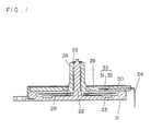
- Figure 1 is a sectional side view of a light-reflecting rotary encoder in one embodiment of this invention
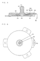
- Figure 2 is a plan view of the embodiment in Figure 1
- Figure 3 is a plan view of a ring-shaped magnetic plate, which is a principal part of the embodiment in Figure 1, and a base member in which the ring-shaped magnetic plate is assembled
- Figure 4 is a diagram showing the operation of the same
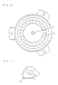
- Figure 5 is a sectional side view of a light-reflecting rotary encoder in another embodiment of this invention
- Figure 6 is a plan view of the embodiment in Figure 5
- Figure 7 is a plan view of an insulating substrate looking from the bottom and showing the arrangement of components
- Figure 8 is a diagram showing the operation of the same
- Figure 9 is a sectional side view of a light-reflecting rotary encoder of the prior art
- Figure 10 is a plan view of a base member which is a principal part of the embodiment in Figure 9
- Figure 11 is a perspective view of a detent spring
- Figure 1 is a sectional side view
- Figure 2 is a plan view
- Figure 3 is a plan view showing a base member in which a ring-shaped magnet, the principal part of the embodiment in Figure 1, is assembled
- Figure 4 is a diagram showing the operation of this embodiment.
- reference numeral 21 denotes a base member made from a material such as die cast zinc as in the prior art.
- a cylindrical support shaft 22 extends perpendicularly up from the center of the disc-shaped bottom surface of the base member and a ring-shaped magnetic plate 23 is positioned at a fixed radius from the center of the base member.
- the ring-shaped magnetic plate 23 is divided into a plurality of equal parts, at which magnetic portions 23' and non-magnetic portions 23" are alternately disposed.
- the support shaft 22 supports an operating shaft 24 rotatably, and in the vicinity of the lower end thereof, a pulse plate 28 which is the same as that of the prior art is provided.
- a pulse plate 28 which is made from a thin sheet of glossy iron material, glossy light-reflective portions 26 and non-reflective slits 27 are alternately and continuously positioned at about the same radius as the ring-shaped magnetic plate 23 on the bottom surface of the base member 21, the respective number of the light-reflective portions 26 and the non-reflective slits 27 being the same as that of the magnetic portions 23' on the magnetic plate.
- the reference numeral 35 is a retainer washer for holding the operating shaft 24 in place.
- an optical element 33 of reflective detector type in which a light-emitting element 31 and light-receiving element 32 are arranged side by side is fixed to and has continuity with a conductor plate 30 which is formed inside an insulating substrate 29 fixed on the upper surface of the base member 21, so that the optical element opposes the light-reflective glossy portions 26 and non-reflective slits 27 of the above-mentioned pulse plate 28.
- the optical element 33 engages with the pulse plate 28 attached to the above-mentioned operating shaft 24 so as to generate pulse signals.
- the pulling force P2 of the next magnetic portion 23' gradually becomes stronger than P1, resulting in that the pulse plate 28 rotates without the help of any external force to a position where the light-reflective portions 26 oppose the next magnetic portions 23', respectively.
- the hand of the person rotating the operating shaft 24 at this time senses a click, and electrically, the light-reflective portion 26 and the non-reflective slit 27 of the pulse plate 28 passes by the optical element 33 one by one, which outputs a pulse signal to terminals 34 in the same manner as in the prior art.
- the same thing occurs when the operating shaft is rotated to the left.
- the top surface of the ring magnet is colored a flat black. Also, by disposing two optical elements 33 and outputting signals with shifted phases according to the direction of rotation, it is possible to distinguish the direction of rotation together with the pulse signals.
- Figure 5 is a sectional side view
- Figure 6 is a plan view of the rotary encoder of Figure 5
- Figure 7 is a plan view looking up from the bottom of an insulating substrate and showing the arrangement of components of the same
- Figure 8 is a diagram showing the operation of the same.
- reference numeral 41 denotes a base member made from a material such as die cast zinc as in the prior art.
- a cylindrical support shaft 42 extending perpendicularly up from the center of the disc-shaped bottom surface of the base member supports an operating shaft 43 rotatably, the operating shaft being secured in place by a retainer washer 44.
- a circular pulse plate 45 made from a thin sheet of iron material is attached in the vicinity of the lower end of the operating shaft 43.
- This circular pulse plate 45 is radially divided into fan-shaped equal portions in the same manner as in the prior art, and half of them serve as non-reflective slits 46 while the other half serve as light-reflective portions 47 having glossy upper surfaces.
- an annulus which is defined by almost the same inner and outer radii as the non-reflective slits 46 and light-reflective portions 47 of the above-mentioned circular pulse plate 45 is divided into four equal parts, and at two of them opposing to each other, two fan-shaped magnetic plates 49 and 49' are respectively attached so as to face the circular pulse plate 45.
- these two fan-shaped magnetic plates 49 and 49' comprise magnetic portions 50 and 50' and non-magnetic portions 51 and 51', respectively, which have the same angle of pitch as the non-reflective slits 46 and light-reflective portions 47.
- An optical element 54 of reflective detector type in which a light-emitting element 52 and light-receiving element 53 are arranged side by side is attached to the insulating substrate 48 and between the two fan-shaped magnetic plates 49 and 49' so that the optical element opposes the non-reflective slits 46 and light-reflective portions 47 on the circular pulse plate 45.
- the optical element 54 is fixed to and has continuity with a conductor plate 56 which has continuity with terminals 55.
- the clicking detent sensation in this embodiment is weaker than in the prior art due to the smaller number of magnetic portions on the magnetic plates, but this can be changed by increasing the magnetic density of each magnetic portion or decreasing the distance between the magnetic plate and the circular pulse plate.
- the fan-shaped magnetic plates 49 and 49' for producing the clicking detent sensation and the optical element 54 for generating pulse signals were attached to the insulating substrate 48 above the top surface of the circular pulse plate, but it is possible to form the base member from an insulating material and attach the fan-shaped magnetic plates and optical element to the circular bottom surface below the circular pulse plate.
- the above embodiment used two fan-shaped magnetic plates which are provided by dividing an annulus equally, but it is also possible to use three or four plates.
- the second embodiment shown in Figures 5 through 8 has the following advantages:
- both of the magnetic plates for generating a clicking detent and the optical element for generating pulse signals are disposed on either the upper or lower surface of the circular pulse plate, the box-like base member or insulating substrate on the side of the pulse plate to which the above magnetic plates and optical element are not attached can be made flat and thin.
- this invention has the following features:
- the pulse plate is made from a sheet of iron material, and the clicking detent sensation is produced by the difference in magnetic pulling forces on the light-reflective portions and the non-reflective slits while the pulse signals are generated by detecting whether the light from the light-emitting element of the optical element is reflected by the light-reflective portions or passes through the non-reflective slits of the same pulse plate, so that the timing of the clicking detent sensation and pulse signal generation always agree.
- clicking detent is produced not by contacting some of the components but by utilizing magnetic forces, so that there is no deterioration in the clicking detent sensation due to friction or the like.
- the pulse plate Since the clicking detent sensation is produced by the difference in magnetic pulling forces on the light-reflective portions and non-reflective slits continuously disposed on the pulse plate, the pulse plate is always being pulled by the magnetic forces and the light-reflective portions tend to be pulled to the nearer one of the adjacent magnetic portions on the ring-shaped magnetic plate. Therefore, the pulse plate does not stop at non-magnetic portions between adjacent magnetic portions and a smooth clicking sensation can be obtained.
- a light-reflecting rotary encoder can be provided with no shift in the timing between the clicking detent sensation and pulse signal generation and with a long useful life without any deterioration in the clicking detent sensation.
Applications Claiming Priority (3)
| Application Number | Priority Date | Filing Date | Title |
|---|---|---|---|
| JP63268463A JP2543156B2 (ja) | 1988-10-25 | 1988-10-25 | 光反射式ロ―タリ―エンコ―ダ― |
| JP268463/88 | 1988-10-25 | ||
| PCT/JP1989/001092 WO1990004756A1 (en) | 1988-10-25 | 1989-10-25 | Rotary encoder |
Publications (3)
| Publication Number | Publication Date |
|---|---|
| EP0414900A1 true EP0414900A1 (de) | 1991-03-06 |
| EP0414900A4 EP0414900A4 (en) | 1992-11-04 |
| EP0414900B1 EP0414900B1 (de) | 1994-09-14 |
Family
ID=17458852
Family Applications (1)
| Application Number | Title | Priority Date | Filing Date |
|---|---|---|---|
| EP89911887A Expired - Lifetime EP0414900B1 (de) | 1988-10-25 | 1989-10-25 | Rotierende kodiervorrichtung |
Country Status (6)
| Country | Link |
|---|---|
| US (1) | US5070238A (de) |
| EP (1) | EP0414900B1 (de) |
| JP (1) | JP2543156B2 (de) |
| KR (1) | KR930002720B1 (de) |
| DE (1) | DE68918277T2 (de) |
| WO (1) | WO1990004756A1 (de) |
Cited By (2)
| Publication number | Priority date | Publication date | Assignee | Title |
|---|---|---|---|---|
| EP0498540A2 (de) * | 1991-02-06 | 1992-08-12 | Hewlett-Packard Company | System zur mechanische Feststellsimulation |
| DE4216296A1 (de) * | 1992-05-16 | 1993-11-18 | Miele & Cie | Drehwahlschalter zur Anordnung auf einer Leiterplatte eines elektrischen Gerätes |
Families Citing this family (6)
| Publication number | Priority date | Publication date | Assignee | Title |
|---|---|---|---|---|
| DE68906543T2 (de) * | 1988-10-25 | 1993-11-18 | Matsushita Electric Ind Co Ltd | Rotierende kodierungsanordnung. |
| US5541406A (en) * | 1994-09-26 | 1996-07-30 | Ohmeda Inc. | Pulsed operation of optical rotary encoder for low-power applications |
| US5734173A (en) * | 1996-05-24 | 1998-03-31 | Braun; Paul-Wilhelm | Method and device for positioning of moving machinery parts |
| JP4375055B2 (ja) * | 2004-02-26 | 2009-12-02 | パナソニック株式会社 | 回転型エンコーダ |
| DE102014116827B4 (de) * | 2014-11-18 | 2016-07-14 | Ma Lighting Technology Gmbh | Doppelwellenencoder |
| CN112444277A (zh) | 2019-09-04 | 2021-03-05 | 台达电子工业股份有限公司 | 光学反射部件及其适用的光学编码器 |
Citations (2)
| Publication number | Priority date | Publication date | Assignee | Title |
|---|---|---|---|---|
| FR2309082A1 (fr) * | 1975-04-24 | 1976-11-19 | Serras Paulet Edouard | Dispositif a bouton poussoir de commande de commutation d'un circuit electronique ou electrique |
| US4628199A (en) * | 1983-10-13 | 1986-12-09 | Mueller Michael M | Rotary noiseless detent switch |
Family Cites Families (2)
| Publication number | Priority date | Publication date | Assignee | Title |
|---|---|---|---|---|
| US4356397A (en) * | 1980-06-18 | 1982-10-26 | Westinghouse Electric Corp. | Optical valve position sensor system |
| JPH0355858Y2 (de) * | 1986-06-24 | 1991-12-13 |
-
1988
- 1988-10-25 JP JP63268463A patent/JP2543156B2/ja not_active Expired - Fee Related
-
1989
- 1989-10-25 US US07/499,438 patent/US5070238A/en not_active Expired - Lifetime
- 1989-10-25 DE DE68918277T patent/DE68918277T2/de not_active Expired - Fee Related
- 1989-10-25 KR KR1019900701361A patent/KR930002720B1/ko not_active IP Right Cessation
- 1989-10-25 EP EP89911887A patent/EP0414900B1/de not_active Expired - Lifetime
- 1989-10-25 WO PCT/JP1989/001092 patent/WO1990004756A1/ja active IP Right Grant
Patent Citations (2)
| Publication number | Priority date | Publication date | Assignee | Title |
|---|---|---|---|---|
| FR2309082A1 (fr) * | 1975-04-24 | 1976-11-19 | Serras Paulet Edouard | Dispositif a bouton poussoir de commande de commutation d'un circuit electronique ou electrique |
| US4628199A (en) * | 1983-10-13 | 1986-12-09 | Mueller Michael M | Rotary noiseless detent switch |
Non-Patent Citations (1)
| Title |
|---|
| See also references of WO9004756A1 * |
Cited By (3)
| Publication number | Priority date | Publication date | Assignee | Title |
|---|---|---|---|---|
| EP0498540A2 (de) * | 1991-02-06 | 1992-08-12 | Hewlett-Packard Company | System zur mechanische Feststellsimulation |
| EP0498540A3 (en) * | 1991-02-06 | 1994-07-20 | Hewlett Packard Co | Mechanical detent simulating system |
| DE4216296A1 (de) * | 1992-05-16 | 1993-11-18 | Miele & Cie | Drehwahlschalter zur Anordnung auf einer Leiterplatte eines elektrischen Gerätes |
Also Published As
| Publication number | Publication date |
|---|---|
| DE68918277D1 (de) | 1994-10-20 |
| JP2543156B2 (ja) | 1996-10-16 |
| KR930002720B1 (ko) | 1993-04-09 |
| KR900702330A (ko) | 1990-12-06 |
| EP0414900A4 (en) | 1992-11-04 |
| WO1990004756A1 (en) | 1990-05-03 |
| DE68918277T2 (de) | 1995-05-18 |
| EP0414900B1 (de) | 1994-09-14 |
| JPH02114122A (ja) | 1990-04-26 |
| US5070238A (en) | 1991-12-03 |
Similar Documents
| Publication | Publication Date | Title |
|---|---|---|
| US6246232B1 (en) | Rotation sensor for generating electric signals corresponding to turning angle and turning direction of detection target | |
| EP0149360B1 (de) | Rotationsmessaufnehmer | |
| EP0088624B1 (de) | Optischer Drehsensor | |
| EP0727646A2 (de) | Vorrichtung zur Verschiebungsdetektion sowie Skala und Antriebsapparat dafür | |
| US5070238A (en) | Rotary encoder having circular magnet | |
| KR100271054B1 (ko) | 다회전체의 회전 검출장치 | |
| US4788422A (en) | High resolution rotary encoder having appositely rotating disks | |
| EP0414899B1 (de) | Rotierende kodierungsanordnung | |
| US4580871A (en) | Rotary encoder | |
| US4659924A (en) | Rotary encoder wherein phase difference is adjusted by the radial position of the sensor head | |
| JPH0450771A (ja) | 速度検出器 | |
| US5245487A (en) | Transducer head for rigid disk drive | |
| JPH10132611A (ja) | 回転変位情報検出装置 | |
| JPH067013U (ja) | 光学式エンコーダ | |
| CN212302217U (zh) | 手表 | |
| US5124972A (en) | Mechanism for precise linear movement, and apparatus using such a mechanism for scanning a disc | |
| JPH04278416A (ja) | 電磁誘導式ロータリーエンコーダ | |
| JPH0429551A (ja) | モータ | |
| JP2531814B2 (ja) | サ―ボ制御システム及び固定磁気ディスク駆動装置 | |
| US4091513A (en) | Accurate UHF television tuning system and method of fabricating same | |
| CN111856912A (zh) | 手表 | |
| JPS63210621A (ja) | ロ−タリ−エンコ−ダ | |
| JP2554702Y2 (ja) | 回転方向検出器 | |
| JPH0762622B2 (ja) | 光学式エンコーダ | |
| SU1714342A1 (ru) | Устройство дл измерени перемещений |
Legal Events
| Date | Code | Title | Description |
|---|---|---|---|
| PUAI | Public reference made under article 153(3) epc to a published international application that has entered the european phase |
Free format text: ORIGINAL CODE: 0009012 |
|
| 17P | Request for examination filed |
Effective date: 19900625 |
|
| AK | Designated contracting states |
Kind code of ref document: A1 Designated state(s): DE GB |
|
| A4 | Supplementary search report drawn up and despatched |
Effective date: 19920911 |
|
| AK | Designated contracting states |
Kind code of ref document: A4 Designated state(s): DE GB |
|
| 17Q | First examination report despatched |
Effective date: 19930217 |
|
| GRAA | (expected) grant |
Free format text: ORIGINAL CODE: 0009210 |
|
| AK | Designated contracting states |
Kind code of ref document: B1 Designated state(s): DE GB |
|
| REF | Corresponds to: |
Ref document number: 68918277 Country of ref document: DE Date of ref document: 19941020 |
|
| PLBE | No opposition filed within time limit |
Free format text: ORIGINAL CODE: 0009261 |
|
| STAA | Information on the status of an ep patent application or granted ep patent |
Free format text: STATUS: NO OPPOSITION FILED WITHIN TIME LIMIT |
|
| 26N | No opposition filed | ||
| REG | Reference to a national code |
Ref country code: GB Ref legal event code: IF02 |
|
| PGFP | Annual fee paid to national office [announced via postgrant information from national office to epo] |
Ref country code: GB Payment date: 20061025 Year of fee payment: 18 |
|
| PGFP | Annual fee paid to national office [announced via postgrant information from national office to epo] |
Ref country code: DE Payment date: 20071018 Year of fee payment: 19 |
|
| GBPC | Gb: european patent ceased through non-payment of renewal fee |
Effective date: 20071025 |
|
| PG25 | Lapsed in a contracting state [announced via postgrant information from national office to epo] |
Ref country code: GB Free format text: LAPSE BECAUSE OF NON-PAYMENT OF DUE FEES Effective date: 20071025 |
|
| PG25 | Lapsed in a contracting state [announced via postgrant information from national office to epo] |
Ref country code: DE Free format text: LAPSE BECAUSE OF NON-PAYMENT OF DUE FEES Effective date: 20090501 |