EP0417648A2 - IC card - Google Patents
IC card Download PDFInfo
- Publication number
- EP0417648A2 EP0417648A2 EP90117206A EP90117206A EP0417648A2 EP 0417648 A2 EP0417648 A2 EP 0417648A2 EP 90117206 A EP90117206 A EP 90117206A EP 90117206 A EP90117206 A EP 90117206A EP 0417648 A2 EP0417648 A2 EP 0417648A2
- Authority
- EP
- European Patent Office
- Prior art keywords
- panel
- frame
- card
- resilient projections
- recesses
- Prior art date
- Legal status (The legal status is an assumption and is not a legal conclusion. Google has not performed a legal analysis and makes no representation as to the accuracy of the status listed.)
- Granted
Links
- 239000000853 adhesive Substances 0.000 claims description 20
- 230000001070 adhesive effect Effects 0.000 claims description 20
- 239000000463 material Substances 0.000 claims description 11
- 239000002184 metal Substances 0.000 claims description 3
- 238000010276 construction Methods 0.000 claims description 2
- 230000002452 interceptive effect Effects 0.000 claims 1
- 239000011347 resin Substances 0.000 claims 1
- 229920005989 resin Polymers 0.000 claims 1
- 238000002788 crimping Methods 0.000 description 2
- 230000002093 peripheral effect Effects 0.000 description 2
- 230000001154 acute effect Effects 0.000 description 1
- 238000005452 bending Methods 0.000 description 1
- 239000004065 semiconductor Substances 0.000 description 1
- 229920003002 synthetic resin Polymers 0.000 description 1
- 239000000057 synthetic resin Substances 0.000 description 1
Images


Classifications
-
- B—PERFORMING OPERATIONS; TRANSPORTING
- B42—BOOKBINDING; ALBUMS; FILES; SPECIAL PRINTED MATTER
- B42D—BOOKS; BOOK COVERS; LOOSE LEAVES; PRINTED MATTER CHARACTERISED BY IDENTIFICATION OR SECURITY FEATURES; PRINTED MATTER OF SPECIAL FORMAT OR STYLE NOT OTHERWISE PROVIDED FOR; DEVICES FOR USE THEREWITH AND NOT OTHERWISE PROVIDED FOR; MOVABLE-STRIP WRITING OR READING APPARATUS
- B42D25/00—Information-bearing cards or sheet-like structures characterised by identification or security features; Manufacture thereof
-
- G—PHYSICS
- G06—COMPUTING; CALCULATING OR COUNTING
- G06K—GRAPHICAL DATA READING; PRESENTATION OF DATA; RECORD CARRIERS; HANDLING RECORD CARRIERS
- G06K19/00—Record carriers for use with machines and with at least a part designed to carry digital markings
- G06K19/06—Record carriers for use with machines and with at least a part designed to carry digital markings characterised by the kind of the digital marking, e.g. shape, nature, code
- G06K19/067—Record carriers with conductive marks, printed circuits or semiconductor circuit elements, e.g. credit or identity cards also with resonating or responding marks without active components
- G06K19/07—Record carriers with conductive marks, printed circuits or semiconductor circuit elements, e.g. credit or identity cards also with resonating or responding marks without active components with integrated circuit chips
- G06K19/077—Constructional details, e.g. mounting of circuits in the carrier
-
- B—PERFORMING OPERATIONS; TRANSPORTING
- B42—BOOKBINDING; ALBUMS; FILES; SPECIAL PRINTED MATTER
- B42D—BOOKS; BOOK COVERS; LOOSE LEAVES; PRINTED MATTER CHARACTERISED BY IDENTIFICATION OR SECURITY FEATURES; PRINTED MATTER OF SPECIAL FORMAT OR STYLE NOT OTHERWISE PROVIDED FOR; DEVICES FOR USE THEREWITH AND NOT OTHERWISE PROVIDED FOR; MOVABLE-STRIP WRITING OR READING APPARATUS
- B42D25/00—Information-bearing cards or sheet-like structures characterised by identification or security features; Manufacture thereof
- B42D25/40—Manufacture
- B42D25/45—Associating two or more layers
-
- Y—GENERAL TAGGING OF NEW TECHNOLOGICAL DEVELOPMENTS; GENERAL TAGGING OF CROSS-SECTIONAL TECHNOLOGIES SPANNING OVER SEVERAL SECTIONS OF THE IPC; TECHNICAL SUBJECTS COVERED BY FORMER USPC CROSS-REFERENCE ART COLLECTIONS [XRACs] AND DIGESTS
- Y10—TECHNICAL SUBJECTS COVERED BY FORMER USPC
- Y10S—TECHNICAL SUBJECTS COVERED BY FORMER USPC CROSS-REFERENCE ART COLLECTIONS [XRACs] AND DIGESTS
- Y10S439/00—Electrical connectors
- Y10S439/946—Memory card cartridge
Definitions
- the present invention relates to an IC card which can improve the junction strength of a panel to a frame.
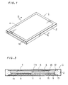
- Fig. 1 is a perspective view showing an example of a conventional IC card
- Fig. 2 is an exploded perspective view of Fig. 1
- Fig. 3 is a sectional view taken along the plane III-III of Fig. 1.
- an IC card 1 consists of a rectangular frame 2, a wiring board 3, and a pair of panels 4 and 5.
- Electronic parts 6 such as a semiconductor memory or the like are installed on a top and a bottom surface of the wiring board 3, respectively, and a hole 7 is formed at the central part of the wiring board 3.
- the frame 2 is made of synthetic resin and has openings 8 in its top and its bottom surface, respectively.
- a convex supporter 9 for supporting the wiring board 3 is provided on an inner surface of the frame 2 along a circumferential direction, and an arm 10 having a projection 11 is provided at a central part of the frame 2 along a cross direction.
- a concavity 12 for supporting the panel 4 is formed in the top surface of the frame 2 along a circumferential direction, while another concavity 13 (see Fig. 3) is formed in the bottom surface of the frame 2 along a circumferential direction, similarly to the concavity 12.
- a plurality of electrodes 14 for inserting contact pins are provided on an end of the frame 2.
- Each of the panels 4 and 5 is made of metal, and has a rectangular form.
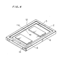
- the IC card 1 is assembled as follow: First, the projection 11 of the frame 2 is passed through the hole 7 of the wiring board 3, and a peripheral part of the wiring board 3 is put on the convex supporter 9. In that state, a tip end of the projection 11 is crimped while being heated to form a crimping part 11a as shown in Fig. 4, whereby the wiring board 3 with the electronic parts 6 is installed in the frame 2 and the electrodes 14 are electrically connected with the electronic parts 6 through the wiring board 3.
- the panels 4 and 5 are glued to the concavities 12 and 13 of the frame 2 through adhesive materials 15 such as an adhesive sheet, adhesive bond or the like, respectively, whereby the panels 4 and 5 cover the openings 8 of the frame 2 while containing the wiring board 3 with the electronic parts 6 in the frame 2.
- the panels 4 and 5 are attached to the frame 2 only by the adhesive strength of the adhesive materials 15. As a result, it yields the problems that a gap results partially between the panels 4, 5 and frame 2 owing to the reduction of the adhesive strength with the lapse of time, or the panel 4 or 5 is partially separated from the frame 2 when the IC card 1 is bent, to thereby deteriorate the quality of the IC card 1.
- An IC card comprises a frame having an opening which is formed on at least one side of a top and a bottom surface thereof, and a plurality of recesses located at a periphery of the opening; electronic parts contained in the frame; and a panel having a plurality of resilient projections located at a periphery of the panel corresponding to the recesses; the panel being mounted on the frame by engaging the respective resilient projections with the respective recesses and covering the opening.
- a principal object of the present invention is to provide an IC card which can improve the performance of the attachment between a panel and a frame.
- the panel since the panel is mounted on the frame by engaging the respective resilient projections of the panel with the respective recesses of the frame, the panel can be securely attached to the frame. And therefore, it can securely prevent the panel from separating from the frame regardless of the lapse of time and any bending operation of the IC card, which eventually makes it possible to improve the quality of the IC card.
- Fig. 5 is a perspective view showing an embodiment of an IC card according to the present invention
- Fig. 6 is an exploded perspective view of Fig. 5
- Fig. 7 is a sectional view taken along the plane VII-VII of Fig. 5.
- each of the panels 4 and 5 is made of an elastic member such as a metal plate or the like.
- the rectangular panel 4 has two opposed long sides 21 and 22 and two opposed short sides 23 and 24, and resilient projections 25 are respectively provided in pairs at each of the long sides 21 and 22.
- each of the resilient projections 25 consists of a protruding piece 25a extending from a back surface of the panel 4 along a vertical direction and a hook 25b formed by folding a top end of the protruding piece 25a at an acute angle ⁇ back toward the respective surface of the panel 4.
- a distance L1 between the one short side 23 and each of the one resilient projections 25 disposed at one end side of the individual long sides 21 and 25 is different from another distance L2 between the other short side 24 and each of the other resilient projections 25 disposed at the other end side of the individual long sides 21 and 22. The reason will be described later.
- the panel 5 has the same construction as the panel 4 but is mounted on the frame 2 in a posture reverse to that of the panel 4. That is, resilient projections 26 similar to the resilient projections 25 of the panel 4 are respectively provided in pairs at each of the long sides of the panel 5, and distances L1 and L2 which represent the position of the resilient projections 26 are determined similarly to those of the panel 4.
- the frame 2 has four recesses 27, which are formed in one concavity 12 and which are located at the periphery of one opening 8 corresponding to the resilient projections 25 of the panel 4.
- each of the recesses 27 comprises an entrance space 27a having a fixed narrow width W and a bottom space 27b whose inner wall 27c forms a slope so that a width of the bottom space 27b becomes larger as it goes to the bottom of the bottom space 27b.
- the recess 27 is formed as a through hole, but the bottom of recess 27 may be closed, if desired.
- the frame 2 has four other recesses 28, which are formed in. the other concavity 13 (see Fig. 7) and which are located at the periphery of the other opening 8 corresponding to the resilient projections 26 of the panel 5.
- each of the recesses 28 has an entrance space 28a, a bottom space 28b and an inner wall 28c similar to the entrance space 27a, the bottom space 27b and the inner wall 27c of the recess 27, respectively, but is formed in a posture reverse to that of the recess 27.
- the IC card 31 is assembled as follows: First, similarly to the case of the conventional IC card 1, the projection 11 of the frame 2 is passed through the hole 7 of the wiring board 3, and the peripheral part of the wiring board 3 is put on the convex supporter 9 of the frame 2. In that state, the tip end of the projection 11 is crimped while being heated to form the crimping part 11a as shown in Fig. 11, whereby the wiring board 3 with the electronic parts 6 is installed in the frame 2 and the electrodes 14 are electrically connected with the electronic parts 6 through the wiring board 3.
- an adhesive material 15 such as an adhesive sheet or the like is allocated on the back surface of the panel 4, and thereafter the panel 4 is impressed on the concavity 12 of the frame 2 to insert the resilient projections 25 of the panel 4 into the recesses 27 of the frame 2.
- each resilient projection 25 passes through the entrance space 27a of the corresponding recess 27 while elastically deforming the hook 25b thereof toward the protruding piece 25a thereof, and then in the bottom space 27b, the hook 25b elastically returns and engages with the inner wall 27c of the bottom space 27b, as shown in Fig. 12. This engagement prevents extracting the resilient projections 25 from the recesses 27.
- the panel 4 is joined to the frame 2 with both the adhesive strength of the adhesive material 15 and the engagement of the resilient projections 25 and the recesses 27.
- Fig. 13 is a view, partially in cross-section, of a portion of the IC card 31, in which the panel 5 is joined to the frame 2 with both the adhesive strength of the adhesive material 15 and the engagement of the resilient projections 26 and the recesses 28.
- the panels 4 and 5 are joined to the frame 2 with the engagement of the resilient projections 25, 26 and the recesses 27, 28 in addition to the adhesion by the adhesive materials 15. Consequently, even if the adhesive strength of the adhesive materials 15 should be deteriorated with the lapse of time, or even if the IC card 31 has been forcibly bent, the panels 4 and 5 remain securely connected to the frame 2 by the engagement of the resilient projections 25, 26 and the recesses 27, 28.
- the panels 4 and 5 have been joined to be frame 2 with both the adhesive strength of the adhesive materials 15 and the engagement of the resilient projections 25, 26 and the recesses 27, 28, the adhesive materials 15 may be omitted according to circumstances.
- the resilient projections 25 (26) have been respectively provided in pairs at each of the long sides 21 and 22 of the panel 4 (5), three or more resilient projections 25 (26) may be respectively provided at each of the long sides 21 and 22 of the panel 4 (5). Furthermore, the resilient projections 25 (26) may be provided at two opposed short sides 23 and 24 of the panel 4 (5) instead of two opposed long sides 21 and 22 of the panel 4 (5), or may be provided at both of two opposed long sides 21 and 22 and two opposed short sides 23 and 24 of the panel 4 (5).
- the panels 4 and 5, the frame 2 and the wiring board 3 are shown as a rectangle respectively, they may be a quadrate respectively.
- the frame 2 has two openings 8 which are respectively formed in the top and the bottom surface thereof and two panels 4 and 5 are mounted in the both surfaces of the frame 2, the frame 2 may have a single opening 8 which is formed in one side of the top and the bottom surface thereof and a single panel 4 or 5 may be mounted in the surface having the opening of the frame 2.
- the wiring board 3 may be installed to the frame 2 by a different way from that described above.
Abstract
Description
- The present invention relates to an IC card which can improve the junction strength of a panel to a frame.
- Fig. 1 is a perspective view showing an example of a conventional IC card, Fig. 2 is an exploded perspective view of Fig. 1, and Fig. 3 is a sectional view taken along the plane III-III of Fig. 1.
- Referring to Figs. 1 to 3, an
IC card 1 consists of arectangular frame 2, awiring board 3, and a pair ofpanels Electronic parts 6 such as a semiconductor memory or the like are installed on a top and a bottom surface of thewiring board 3, respectively, and ahole 7 is formed at the central part of thewiring board 3. - The
frame 2 is made of synthetic resin and hasopenings 8 in its top and its bottom surface, respectively. Aconvex supporter 9 for supporting thewiring board 3 is provided on an inner surface of theframe 2 along a circumferential direction, and anarm 10 having a projection 11 is provided at a central part of theframe 2 along a cross direction. Aconcavity 12 for supporting thepanel 4 is formed in the top surface of theframe 2 along a circumferential direction, while another concavity 13 (see Fig. 3) is formed in the bottom surface of theframe 2 along a circumferential direction, similarly to theconcavity 12. A plurality ofelectrodes 14 for inserting contact pins (not shown) are provided on an end of theframe 2. - Each of the
panels - The
IC card 1 is assembled as follow: First, the projection 11 of theframe 2 is passed through thehole 7 of thewiring board 3, and a peripheral part of thewiring board 3 is put on theconvex supporter 9. In that state, a tip end of the projection 11 is crimped while being heated to form acrimping part 11a as shown in Fig. 4, whereby thewiring board 3 with theelectronic parts 6 is installed in theframe 2 and theelectrodes 14 are electrically connected with theelectronic parts 6 through thewiring board 3. Thereafter, thepanels concavities frame 2 throughadhesive materials 15 such as an adhesive sheet, adhesive bond or the like, respectively, whereby thepanels openings 8 of theframe 2 while containing thewiring board 3 with theelectronic parts 6 in theframe 2. - With the above
conventional IC card 1, thepanels frame 2 only by the adhesive strength of theadhesive materials 15. As a result, it yields the problems that a gap results partially between thepanels frame 2 owing to the reduction of the adhesive strength with the lapse of time, or thepanel frame 2 when theIC card 1 is bent, to thereby deteriorate the quality of theIC card 1. - An IC card according to the present invention comprises a frame having an opening which is formed on at least one side of a top and a bottom surface thereof, and a plurality of recesses located at a periphery of the opening; electronic parts contained in the frame; and a panel having a plurality of resilient projections located at a periphery of the panel corresponding to the recesses; the panel being mounted on the frame by engaging the respective resilient projections with the respective recesses and covering the opening.
- Accordingly, a principal object of the present invention is to provide an IC card which can improve the performance of the attachment between a panel and a frame.
- According to the present invention, since the panel is mounted on the frame by engaging the respective resilient projections of the panel with the respective recesses of the frame, the panel can be securely attached to the frame. And therefore, it can securely prevent the panel from separating from the frame regardless of the lapse of time and any bending operation of the IC card, which eventually makes it possible to improve the quality of the IC card.
- These and other objects, features, aspects and advantages of the present invention will become more apparent from the following detailed description of the present invention when taken in conjunction with the accompanying drawings.
-
- Fig. 1 is a perspective view showing an example of a conventional IC card;
- Fig. 2 is an exploded perspective view of Fig. 1;
- Fig. 3 is a sectional view taken along the plane III-III of Fig. 1;
- Fig. 4 is a perspective view showing the conventional IC card from which a panel is removed;
- Fig. 5 is a perspective view showing an embodiment of an IC card according to the present invention;
- Fig. 6 is an exploded perspective view of Fig. 5;
- Fig. 7 is a sectional view taken along the plane VII-VII of Fig. 5;
- Fig. 8 is a perspective view showing a resilient projection of a panel;
- Fig. 9 is a view, partially in cross-section, of a portion of the IC card with removed panels;
- Fig. 10 is a view, partially in cross-section, of another portion of the IC card with removed panels;
- Fig. 11 is a perspective view showing the IC card from which a panel is removed;
- Fig. 12 is a view, partially in cross-section, of a portion of the IC card with removed panels;
- Fig. 13 is a view, partially in cross-section, of another portion of the IC card with removed panels;
- Fig. 5 is a perspective view showing an embodiment of an IC card according to the present invention, Fig. 6 is an exploded perspective view of Fig. 5, and Fig. 7 is a sectional view taken along the plane VII-VII of Fig. 5.
- Referring to Figs. 5 to 7, each of the
panels rectangular panel 4 has two opposedlong sides short sides resilient projections 25 are respectively provided in pairs at each of thelong sides - As shown in Fig. 8, each of the
resilient projections 25 consists of a protruding piece 25a extending from a back surface of thepanel 4 along a vertical direction and ahook 25b formed by folding a top end of the protruding piece 25a at an acute angle ϑ back toward the respective surface of thepanel 4. - Besides, as shown in Fig. 6, a distance L₁ between the one
short side 23 and each of the oneresilient projections 25 disposed at one end side of the individuallong sides short side 24 and each of the otherresilient projections 25 disposed at the other end side of the individuallong sides - The
panel 5 has the same construction as thepanel 4 but is mounted on theframe 2 in a posture reverse to that of thepanel 4. That is,resilient projections 26 similar to theresilient projections 25 of thepanel 4 are respectively provided in pairs at each of the long sides of thepanel 5, and distances L₁ and L₂ which represent the position of theresilient projections 26 are determined similarly to those of thepanel 4. - The
frame 2 has fourrecesses 27, which are formed in oneconcavity 12 and which are located at the periphery of oneopening 8 corresponding to theresilient projections 25 of thepanel 4. - As shown in Fig. 9, each of the
recesses 27 comprises anentrance space 27a having a fixed narrow width W and abottom space 27b whoseinner wall 27c forms a slope so that a width of thebottom space 27b becomes larger as it goes to the bottom of thebottom space 27b. In this embodiment, therecess 27 is formed as a through hole, but the bottom ofrecess 27 may be closed, if desired. - On the other hand, the
frame 2 has fourother recesses 28, which are formed in. the other concavity 13 (see Fig. 7) and which are located at the periphery of theother opening 8 corresponding to theresilient projections 26 of thepanel 5. - As shown in Fig. 10, each of the
recesses 28 has anentrance space 28a, abottom space 28b and aninner wall 28c similar to theentrance space 27a, thebottom space 27b and theinner wall 27c of therecess 27, respectively, but is formed in a posture reverse to that of therecess 27. - As is apparent from Fig. 6, since the distances L₁ and L₂ which represent the positions of the
resilient projections panels recesses frame 2. - Since the other structure of the
IC card 31 is similar to that of theIC card 1, the same reference numerals are used in the same parts, and hence further explanation thereof will be omitted. - The
IC card 31 is assembled as follows: First, similarly to the case of theconventional IC card 1, the projection 11 of theframe 2 is passed through thehole 7 of thewiring board 3, and the peripheral part of thewiring board 3 is put on theconvex supporter 9 of theframe 2. In that state, the tip end of the projection 11 is crimped while being heated to form thecrimping part 11a as shown in Fig. 11, whereby thewiring board 3 with theelectronic parts 6 is installed in theframe 2 and theelectrodes 14 are electrically connected with theelectronic parts 6 through thewiring board 3. - Next, an adhesive material 15 (see Fig. 7) such as an adhesive sheet or the like is allocated on the back surface of the
panel 4, and thereafter thepanel 4 is impressed on theconcavity 12 of theframe 2 to insert theresilient projections 25 of thepanel 4 into therecesses 27 of theframe 2. As a result, eachresilient projection 25 passes through theentrance space 27a of thecorresponding recess 27 while elastically deforming thehook 25b thereof toward the protruding piece 25a thereof, and then in thebottom space 27b, thehook 25b elastically returns and engages with theinner wall 27c of thebottom space 27b, as shown in Fig. 12. This engagement prevents extracting theresilient projections 25 from therecesses 27. Thus, thepanel 4 is joined to theframe 2 with both the adhesive strength of theadhesive material 15 and the engagement of theresilient projections 25 and therecesses 27. - Finally, the
other panel 5 is joined to the concavity 13 (see Fig. 7) formed at the bottom surface of theframe 2, similarly to a case of thepanel 4. Fig. 13 is a view, partially in cross-section, of a portion of theIC card 31, in which thepanel 5 is joined to theframe 2 with both the adhesive strength of theadhesive material 15 and the engagement of theresilient projections 26 and therecesses 28. - According to the
IC card 31, thepanels frame 2 with the engagement of theresilient projections recesses adhesive materials 15. Consequently, even if the adhesive strength of theadhesive materials 15 should be deteriorated with the lapse of time, or even if theIC card 31 has been forcibly bent, thepanels frame 2 by the engagement of theresilient projections recesses - In the above embodiment, although the
panels frame 2 with both the adhesive strength of theadhesive materials 15 and the engagement of theresilient projections recesses adhesive materials 15 may be omitted according to circumstances. - In the above embodiment, although the resilient projections 25 (26) have been respectively provided in pairs at each of the
long sides long sides short sides long sides long sides short sides - In the above embodiment, although the
panels frame 2 and thewiring board 3 are shown as a rectangle respectively, they may be a quadrate respectively. - In the above embodiment, although the
frame 2 has twoopenings 8 which are respectively formed in the top and the bottom surface thereof and twopanels frame 2, theframe 2 may have asingle opening 8 which is formed in one side of the top and the bottom surface thereof and asingle panel frame 2. - Besides, the
wiring board 3 may be installed to theframe 2 by a different way from that described above. - Although the present invention has been described and illustrated in detail, it is clearly understood that the same is by way of illustration and example only and is not to be taken by way of limitation.
Claims (9)
- a frame (2) having an opening (8) which is formed in at least one side of a top and a bottom surface thereof, and a plurality of recesses (27, 28) located at the periphery of the opening (8);
electronic parts (6) contained in the frame (2); and
- a panel (4, 5) having a plurality of resilient projections (25, 26) located at the periphery of the panel (4, 5) corresponding to the recesses (27, 28);
- the panel (4, 5) being mounted in the frame (2) by engaging the respective resilient projections (25, 26) with the respective recesses (27, 28) and covering the opening (8).
- each of the resilient projections (25, 26) consists of a protruding piece (25a) extending from a back surface of the panel along a vertical direction and a hook (25b) formed by folding a top end of the protruding piece (25a) back toward the respective surface of the panel (4, 5), while each of the recesses (27, 28) consists of an entrance space (27a, 28a) having a fixed narrow width (W) and a bottom space (27b, 28b) whose inner wall (27c, 28c) forms a slope so that the width of the bottom space (27b, 28b) becomes larger as it goes to the bottom of the bottom space (27b, 28b), and
- each of the resilient projections (25, 26) passes through the respective entrance space (27a, 28a) while the hook (25b) is elastically deformed toward the protruding piece (25a), and engages the hook (25b) elastically returned with the inner wall (27c, 28c) of the bottom space (27a, 28b).
- the frame (2) has two openings (8) which are respectively formed in the top and the bottom surface thereof,
- the card has two panels (4, 5), one of which covers the one opening (8) and the other of which covers the other opening (8), and
- the two panels (4, 5) have the same construction but are mounted in the frame (2) in a posture reverse to each other, in each of which a distance (L1) between a short side (23, 24) and each of the one resilient projections (25, 26) disposed at one end side of individual long sides (21, 22) is different from that between the other short side and each of the other resilient projections (25, 26) disposed at the other end side of the individual long sides (21, 22), in order to prevent the resilient projections (25) of the one panel (4) and the resilient projections (26) of the other panel (5) from interfering with each other.
Applications Claiming Priority (2)
| Application Number | Priority Date | Filing Date | Title |
|---|---|---|---|
| JP233475/89 | 1989-09-09 | ||
| JP1233475A JPH07121635B2 (en) | 1989-09-09 | 1989-09-09 | IC card |
Publications (3)
| Publication Number | Publication Date |
|---|---|
| EP0417648A2 true EP0417648A2 (en) | 1991-03-20 |
| EP0417648A3 EP0417648A3 (en) | 1991-07-03 |
| EP0417648B1 EP0417648B1 (en) | 1996-02-14 |
Family
ID=16955600
Family Applications (1)
| Application Number | Title | Priority Date | Filing Date |
|---|---|---|---|
| EP90117206A Expired - Lifetime EP0417648B1 (en) | 1989-09-09 | 1990-09-06 | IC card |
Country Status (5)
| Country | Link |
|---|---|
| US (1) | US5038250A (en) |
| EP (1) | EP0417648B1 (en) |
| JP (1) | JPH07121635B2 (en) |
| KR (1) | KR930000556B1 (en) |
| DE (1) | DE69025365T2 (en) |
Cited By (16)
| Publication number | Priority date | Publication date | Assignee | Title |
|---|---|---|---|---|
| EP0532160A2 (en) * | 1991-09-09 | 1993-03-17 | ITT INDUSTRIES, INC. (a Delaware corporation) | Card grounding system |
| EP0546680A1 (en) * | 1991-12-09 | 1993-06-16 | International Business Machines Corporation | Jacketted circuit card |
| EP0564051A1 (en) * | 1992-04-02 | 1993-10-06 | N.V. Nederlandsche Apparatenfabriek NEDAP | Identification card having a reusable inner part |
| EP0578888A1 (en) * | 1992-06-29 | 1994-01-19 | ITT INDUSTRIES, INC. (a Delaware corporation) | Data card perimeter shield |
| EP0671704A1 (en) * | 1994-03-11 | 1995-09-13 | Molex Incorporated | Grounded IC card |
| EP0717472A2 (en) * | 1994-12-13 | 1996-06-19 | Molex Incorporated | Grounding clip for IC-cards |
| WO1996030944A2 (en) * | 1995-03-30 | 1996-10-03 | Siemens Aktiengesellschaft | Support module |
| US5606704A (en) * | 1994-10-26 | 1997-02-25 | Intel Corporation | Active power down for PC card I/O applications |
| US5749741A (en) * | 1996-07-12 | 1998-05-12 | Minnesota Mining And Manufacturing Company | Electrical connector with ground clip |
| US5846092A (en) * | 1997-08-05 | 1998-12-08 | Minnesota Mining And Manufacturing Company | Plastic cased IC card adapter assembly |
| EP0999492A2 (en) * | 1991-07-19 | 2000-05-10 | Kabushiki Kaisha Toshiba | Card-shaped electronic device |
| WO2003067604A2 (en) * | 2002-02-08 | 2003-08-14 | Conti Temic Microelectronic Gmbh | Circuit system with a printed board comprising a programmable memory element |
| GB2430082A (en) * | 2005-09-12 | 2007-03-14 | D & C Technology Co Ltd | Package structure for an interface card |
| WO2008113645A1 (en) * | 2007-03-21 | 2008-09-25 | Continental Automotive Gmbh | Electronic component |
| DE102008018221B4 (en) * | 2007-05-07 | 2011-05-12 | Infineon Technologies Ag | System with protection for circuit boards |
| US8625298B2 (en) | 2007-02-09 | 2014-01-07 | Infineon Technologies Ag | Protection for circuit boards |
Families Citing this family (61)
| Publication number | Priority date | Publication date | Assignee | Title |
|---|---|---|---|---|
| US5157245A (en) * | 1988-06-29 | 1992-10-20 | Murata Mfg. Co., Ltd. | Magnetic sensor |
| JPH07121636B2 (en) * | 1989-09-27 | 1995-12-25 | 三菱電機株式会社 | Semiconductor device card |
| JP2582477B2 (en) * | 1990-12-05 | 1997-02-19 | 富士写真フイルム株式会社 | Memory card |
| JPH04263998A (en) * | 1991-02-19 | 1992-09-18 | Mitsubishi Electric Corp | Memory card |
| US5208732A (en) * | 1991-05-29 | 1993-05-04 | Texas Instruments, Incorporated | Memory card with flexible conductor between substrate and metal cover |
| US5242310A (en) * | 1992-06-19 | 1993-09-07 | Data Trek Corporation | PC I/O card |
| FR2693621B1 (en) * | 1992-07-08 | 1994-09-16 | Sextant Avionique | Modular structure for a printed circuit card holder, capable of engaging, like a drawer, in a bay of an electronic installation. |
| JPH06171275A (en) * | 1992-09-29 | 1994-06-21 | Mitsubishi Electric Corp | Ic card and production thereof |
| US5836775A (en) * | 1993-05-13 | 1998-11-17 | Berg Tehnology, Inc. | Connector apparatus |
| US5476387A (en) * | 1993-06-07 | 1995-12-19 | Methode Electronics Inc. | Memory card frame and cover kit |
| US5397857A (en) * | 1993-07-15 | 1995-03-14 | Dual Systems | PCMCIA standard memory card frame |
| US5386340A (en) * | 1993-08-13 | 1995-01-31 | Kurz; Arthur A. | Enclosure for personal computer card GPT |
| US5481434A (en) * | 1993-10-04 | 1996-01-02 | Molex Incorporated | Memory card and frame for assembly therefor |
| US5409385A (en) * | 1993-10-07 | 1995-04-25 | Genrife Company Limited | I/O card and connection mechanism thereof |
| US5413490A (en) * | 1993-10-26 | 1995-05-09 | Genrife Company Limited | IC card with generally efficient circumferential shielding |
| US6773291B1 (en) | 1993-11-12 | 2004-08-10 | Intel Corporation | Compliant communications connectors |
| US7074061B1 (en) | 1993-11-12 | 2006-07-11 | Intel Corporation | Versatile communications connectors |
| US5773332A (en) * | 1993-11-12 | 1998-06-30 | Xircom, Inc. | Adaptable communications connectors |
| US5477421A (en) * | 1993-11-18 | 1995-12-19 | Itt Corporation | Shielded IC card |
| US5457601A (en) * | 1993-12-08 | 1995-10-10 | At&T Corp. | Credit card-sized modem with modular DAA |
| US5470241A (en) * | 1993-12-21 | 1995-11-28 | The Whitaker Corporation | Retention mechanism for memory cards |
| US5726867A (en) * | 1994-01-21 | 1998-03-10 | The Whitaker Corporation | Card holder for computers and related equipment |
| WO1995022181A1 (en) * | 1994-02-15 | 1995-08-17 | Berg Technology, Inc. | Shielded circuit board connector module |
| US5497297A (en) * | 1994-06-28 | 1996-03-05 | Intel Corporation | Frame and cover structure for integrated circuit cards |
| US5530622A (en) * | 1994-12-23 | 1996-06-25 | National Semiconductor Corporation | Electronic assembly for connecting to an electronic system and method of manufacture thereof |
| JP2847628B2 (en) | 1995-10-25 | 1999-01-20 | 日本航空電子工業株式会社 | PC card |
| US6091605A (en) * | 1996-04-26 | 2000-07-18 | Ramey; Samuel C. | Memory card connector and cover apparatus and method |
| US5754404A (en) * | 1996-05-14 | 1998-05-19 | Itt Cannon Gmbh | IC card rear board-connector support |
| JPH10166768A (en) * | 1996-12-11 | 1998-06-23 | Mitsubishi Electric Corp | Ic card |
| JP2846301B2 (en) | 1997-06-11 | 1999-01-13 | 松下電器産業株式会社 | Adapter card for memory card |
| US5940275A (en) * | 1997-08-08 | 1999-08-17 | Xircom, Inc. | PCMCIA card frame connector and cover assembly |
| US6089920A (en) * | 1998-05-04 | 2000-07-18 | Micron Technology, Inc. | Modular die sockets with flexible interconnects for packaging bare semiconductor die |
| USD416884S (en) * | 1998-08-05 | 1999-11-23 | Honda Tsushin Kogyo Co., Ltd. | Upper metal cover for compact flash card |
| USD416885S (en) * | 1998-08-05 | 1999-11-23 | Honda Tsushin Kogyo Co., Ltd. | Lower metal cover for compact flash card |
| US6166324A (en) * | 1998-08-06 | 2000-12-26 | Methode Electronics, Inc. | PC card housing with insulative cover and ground feature |
| USD434771S (en) * | 1999-10-05 | 2000-12-05 | Honda Tsushin Kogyo Co., Ltd. | Upper metal cover for compact flash card |
| TW498285B (en) * | 1999-12-17 | 2002-08-11 | Tyco Electronics Corportion | PCMCIA card |
| CN1452788A (en) * | 2000-03-31 | 2003-10-29 | 株式会社日立制作所 | Semiconductor device and its mfg. method |
| DE10208168C1 (en) * | 2002-02-26 | 2003-08-14 | Infineon Technologies Ag | Data card has cover, which presses substrate and components down into recess and along its base, when attached |
| DE10248119B3 (en) * | 2002-10-09 | 2004-06-24 | ITT Manufacturing Enterprises, Inc., Wilmington | Plug-in card for electronic data processing devices |
| KR100801096B1 (en) * | 2003-08-26 | 2008-02-04 | 마츠시타 덴끼 산교 가부시키가이샤 | Pc card |
| US20050281014A1 (en) * | 2004-06-21 | 2005-12-22 | Carullo Thomas J | Surrogate card for printed circuit board assembly |
| CN2760820Y (en) * | 2004-12-01 | 2006-02-22 | 富士康(昆山)电脑接插件有限公司 | Electronic card connector holding structure |
| US7556205B2 (en) * | 2005-01-05 | 2009-07-07 | Chun Chee Tsang | Adaptable media card storage device |
| US7033223B1 (en) * | 2005-03-18 | 2006-04-25 | Chant Sincere Co., Ltd. | Simulated mini SD memory card converter |
| TWI283806B (en) * | 2005-06-07 | 2007-07-11 | Htc Corp | Portable electronic device |
| US7751199B2 (en) | 2006-09-11 | 2010-07-06 | Apple Inc. | Support tabs for protecting a circuit board from applied forces |
| US7489515B2 (en) * | 2006-10-31 | 2009-02-10 | Broadtek Technology Co., Ltd. | Expansion card |
| TWI358626B (en) * | 2008-09-05 | 2012-02-21 | Asustek Comp Inc | Electronic device and engaging structure thereof |
| KR20100030126A (en) * | 2008-09-09 | 2010-03-18 | 삼성전자주식회사 | Memory device and electronic apparatus comprising the same |
| USD794034S1 (en) * | 2009-01-07 | 2017-08-08 | Samsung Electronics Co., Ltd. | Memory device |
| USD794644S1 (en) * | 2009-01-07 | 2017-08-15 | Samsung Electronics Co., Ltd. | Memory device |
| USD795261S1 (en) * | 2009-01-07 | 2017-08-22 | Samsung Electronics Co., Ltd. | Memory device |
| USD794642S1 (en) * | 2009-01-07 | 2017-08-15 | Samsung Electronics Co., Ltd. | Memory device |
| USD795262S1 (en) * | 2009-01-07 | 2017-08-22 | Samsung Electronics Co., Ltd. | Memory device |
| USD794641S1 (en) * | 2009-01-07 | 2017-08-15 | Samsung Electronics Co., Ltd. | Memory device |
| USD794643S1 (en) * | 2009-01-07 | 2017-08-15 | Samsung Electronics Co., Ltd. | Memory device |
| KR20100101958A (en) * | 2009-03-10 | 2010-09-20 | 삼성전자주식회사 | Solid state disk comprising super capacitor |
| US8665601B1 (en) * | 2009-09-04 | 2014-03-04 | Bitmicro Networks, Inc. | Solid state drive with improved enclosure assembly |
| CN203722975U (en) * | 2013-11-19 | 2014-07-16 | 中兴通讯股份有限公司 | Heat-dissipation device for mobile terminal, and shielding case frame |
| CN204463819U (en) * | 2015-01-20 | 2015-07-08 | 环旭电子股份有限公司 | A kind of sectional casing and solid state hard disc |
Citations (3)
| Publication number | Priority date | Publication date | Assignee | Title |
|---|---|---|---|---|
| US4322001A (en) * | 1980-10-29 | 1982-03-30 | Hurley Patrick S | Protective case for a sports card or similar collectible article |
| FR2586886A1 (en) * | 1985-08-09 | 1987-03-06 | Sharp Kk | CARD TYPE THIN ELECTRONIC DEVICE. |
| US4868713A (en) * | 1987-03-31 | 1989-09-19 | Mitsubishi Denki Kabushiki Kaisha | Memory card housing a smiconductor device |
Family Cites Families (2)
| Publication number | Priority date | Publication date | Assignee | Title |
|---|---|---|---|---|
| US4149027A (en) * | 1977-05-27 | 1979-04-10 | Atari, Inc. | TV game cartridge and method |
| US4729741A (en) * | 1986-09-26 | 1988-03-08 | Peng Su C | Safety socket |
-
1989
- 1989-09-09 JP JP1233475A patent/JPH07121635B2/en not_active Expired - Lifetime
-
1990
- 1990-08-07 US US07/563,346 patent/US5038250A/en not_active Expired - Fee Related
- 1990-09-06 EP EP90117206A patent/EP0417648B1/en not_active Expired - Lifetime
- 1990-09-06 DE DE69025365T patent/DE69025365T2/en not_active Expired - Fee Related
- 1990-09-08 KR KR1019900014184A patent/KR930000556B1/en not_active IP Right Cessation
Patent Citations (3)
| Publication number | Priority date | Publication date | Assignee | Title |
|---|---|---|---|---|
| US4322001A (en) * | 1980-10-29 | 1982-03-30 | Hurley Patrick S | Protective case for a sports card or similar collectible article |
| FR2586886A1 (en) * | 1985-08-09 | 1987-03-06 | Sharp Kk | CARD TYPE THIN ELECTRONIC DEVICE. |
| US4868713A (en) * | 1987-03-31 | 1989-09-19 | Mitsubishi Denki Kabushiki Kaisha | Memory card housing a smiconductor device |
Cited By (33)
| Publication number | Priority date | Publication date | Assignee | Title |
|---|---|---|---|---|
| EP0999492A2 (en) * | 1991-07-19 | 2000-05-10 | Kabushiki Kaisha Toshiba | Card-shaped electronic device |
| EP0999492A3 (en) * | 1991-07-19 | 2000-06-14 | Kabushiki Kaisha Toshiba | Card-shaped electronic device |
| USRE35832E (en) * | 1991-09-09 | 1998-06-30 | Itt Corporation | Electrostatically protected IC card |
| EP0532160A3 (en) * | 1991-09-09 | 1993-04-21 | Itt Industries, Inc. | Card grounding system |
| US5319516A (en) * | 1991-09-09 | 1994-06-07 | Itt Corporation | Electrostatically protected IC card |
| EP0682322A3 (en) * | 1991-09-09 | 1999-02-03 | Itt Manufacturing Enterprises, Inc. | An IC card |
| EP0532160A2 (en) * | 1991-09-09 | 1993-03-17 | ITT INDUSTRIES, INC. (a Delaware corporation) | Card grounding system |
| EP0682322A2 (en) | 1991-09-09 | 1995-11-15 | Itt Industries, Inc. | An IC card |
| EP0546680A1 (en) * | 1991-12-09 | 1993-06-16 | International Business Machines Corporation | Jacketted circuit card |
| EP0564051A1 (en) * | 1992-04-02 | 1993-10-06 | N.V. Nederlandsche Apparatenfabriek NEDAP | Identification card having a reusable inner part |
| US5572408A (en) * | 1992-06-29 | 1996-11-05 | Itt Corporation | Card perimeter shield |
| US5333100A (en) * | 1992-06-29 | 1994-07-26 | Itt Corporation | Data card perimeter shield |
| EP0578888A1 (en) * | 1992-06-29 | 1994-01-19 | ITT INDUSTRIES, INC. (a Delaware corporation) | Data card perimeter shield |
| EP0671704A1 (en) * | 1994-03-11 | 1995-09-13 | Molex Incorporated | Grounded IC card |
| US5606704A (en) * | 1994-10-26 | 1997-02-25 | Intel Corporation | Active power down for PC card I/O applications |
| EP0717472A2 (en) * | 1994-12-13 | 1996-06-19 | Molex Incorporated | Grounding clip for IC-cards |
| EP0717472A3 (en) * | 1994-12-13 | 1999-03-31 | Molex Incorporated | Grounding clip for IC-cards |
| WO1996030944A2 (en) * | 1995-03-30 | 1996-10-03 | Siemens Aktiengesellschaft | Support module |
| WO1996030944A3 (en) * | 1995-03-30 | 1996-11-28 | Siemens Ag | Support module |
| US5749741A (en) * | 1996-07-12 | 1998-05-12 | Minnesota Mining And Manufacturing Company | Electrical connector with ground clip |
| US5893766A (en) * | 1996-07-12 | 1999-04-13 | Minnesota Mining And Manufacturing Company | Electrical connector with ground clip |
| US5846092A (en) * | 1997-08-05 | 1998-12-08 | Minnesota Mining And Manufacturing Company | Plastic cased IC card adapter assembly |
| WO1999008232A1 (en) * | 1997-08-05 | 1999-02-18 | Minnesota Mining And Manufacturing Company | Plastic cased ic card adapter assembly |
| WO2003067604A2 (en) * | 2002-02-08 | 2003-08-14 | Conti Temic Microelectronic Gmbh | Circuit system with a printed board comprising a programmable memory element |
| WO2003067604A3 (en) * | 2002-02-08 | 2003-12-11 | Conti Temic Microelectronic | Circuit system with a printed board comprising a programmable memory element |
| GB2430082A (en) * | 2005-09-12 | 2007-03-14 | D & C Technology Co Ltd | Package structure for an interface card |
| GB2430082B (en) * | 2005-09-12 | 2007-08-01 | D & C Technology Co Ltd | Package structure for an interface card |
| US8625298B2 (en) | 2007-02-09 | 2014-01-07 | Infineon Technologies Ag | Protection for circuit boards |
| WO2008113645A1 (en) * | 2007-03-21 | 2008-09-25 | Continental Automotive Gmbh | Electronic component |
| US8300415B2 (en) | 2007-03-21 | 2012-10-30 | Continental Automotive Gmbh | Electronic component |
| DE102008018221B4 (en) * | 2007-05-07 | 2011-05-12 | Infineon Technologies Ag | System with protection for circuit boards |
| US8522051B2 (en) | 2007-05-07 | 2013-08-27 | Infineon Technologies Ag | Protection for circuit boards |
| DE102008064723B4 (en) * | 2007-05-07 | 2017-05-11 | Infineon Technologies Ag | System for protection of circuit boards against unauthorized intervention |
Also Published As
| Publication number | Publication date |
|---|---|
| DE69025365D1 (en) | 1996-03-28 |
| KR910006041A (en) | 1991-04-27 |
| EP0417648A3 (en) | 1991-07-03 |
| DE69025365T2 (en) | 1996-09-19 |
| US5038250A (en) | 1991-08-06 |
| JPH0396394A (en) | 1991-04-22 |
| EP0417648B1 (en) | 1996-02-14 |
| KR930000556B1 (en) | 1993-01-25 |
| JPH07121635B2 (en) | 1995-12-25 |
Similar Documents
| Publication | Publication Date | Title |
|---|---|---|
| EP0417648B1 (en) | IC card | |
| EP0459044B1 (en) | IC card | |
| US5912806A (en) | IC card of simple structure | |
| US6158915A (en) | Attachment member for board materials | |
| US5249974A (en) | Multi-contact connector | |
| US5131853A (en) | Low profile receptacle terminal for soldering to a circuit board | |
| US5278445A (en) | Semiconductor device card having a plurality of self-locking pawls | |
| US6324064B1 (en) | Interface device for chip cards | |
| US6811443B2 (en) | Electronic component having high mechanical strength and method of manufacturing a metal cover included in the electronic component | |
| US7442880B2 (en) | Contact spring assembly | |
| US5490044A (en) | Electric terminal assembly | |
| EP0361642A2 (en) | Coupler terminal unit for speaker | |
| US5086336A (en) | Semiconductor device card | |
| US5117329A (en) | Mounting structure for flexible printed wiring board having holding ribs and auxiliary ribs protruding therebetween | |
| US6195054B1 (en) | IC card with antenna | |
| JP2593221B2 (en) | IC card | |
| US5651695A (en) | Connector for electric wires | |
| JP2986874B2 (en) | Terminal device | |
| JP2696305B2 (en) | Connector mounting device | |
| JP3042218B2 (en) | Electromagnetic relay socket | |
| US6481633B1 (en) | IC incorporating card with a grounding structure | |
| JPH0619147Y2 (en) | Built-in filter connector | |
| JPS6223056Y2 (en) | ||
| JP3012677U (en) | Terminal board | |
| JPH03181197A (en) | Box body structure of electronic device |
Legal Events
| Date | Code | Title | Description |
|---|---|---|---|
| PUAI | Public reference made under article 153(3) epc to a published international application that has entered the european phase |
Free format text: ORIGINAL CODE: 0009012 |
|
| 17P | Request for examination filed |
Effective date: 19901212 |
|
| AK | Designated contracting states |
Kind code of ref document: A2 Designated state(s): DE FR GB |
|
| PUAL | Search report despatched |
Free format text: ORIGINAL CODE: 0009013 |
|
| AK | Designated contracting states |
Kind code of ref document: A3 Designated state(s): DE FR GB |
|
| 17Q | First examination report despatched |
Effective date: 19940520 |
|
| RAP1 | Party data changed (applicant data changed or rights of an application transferred) |
Owner name: MITSUBISHI DENKI KABUSHIKI KAISHA |
|
| GRAH | Despatch of communication of intention to grant a patent |
Free format text: ORIGINAL CODE: EPIDOS IGRA |
|
| GRAA | (expected) grant |
Free format text: ORIGINAL CODE: 0009210 |
|
| AK | Designated contracting states |
Kind code of ref document: B1 Designated state(s): DE FR GB |
|
| REF | Corresponds to: |
Ref document number: 69025365 Country of ref document: DE Date of ref document: 19960328 |
|
| REG | Reference to a national code |
Ref country code: GB Ref legal event code: 727 |
|
| REG | Reference to a national code |
Ref country code: GB Ref legal event code: 727B |
|
| ET | Fr: translation filed | ||
| REG | Reference to a national code |
Ref country code: GB Ref legal event code: 727B |
|
| REG | Reference to a national code |
Ref country code: GB Ref legal event code: SP |
|
| PLBE | No opposition filed within time limit |
Free format text: ORIGINAL CODE: 0009261 |
|
| STAA | Information on the status of an ep patent application or granted ep patent |
Free format text: STATUS: NO OPPOSITION FILED WITHIN TIME LIMIT |
|
| 26N | No opposition filed | ||
| PGFP | Annual fee paid to national office [announced via postgrant information from national office to epo] |
Ref country code: DE Payment date: 20000828 Year of fee payment: 11 |
|
| PGFP | Annual fee paid to national office [announced via postgrant information from national office to epo] |
Ref country code: GB Payment date: 20000906 Year of fee payment: 11 |
|
| PGFP | Annual fee paid to national office [announced via postgrant information from national office to epo] |
Ref country code: FR Payment date: 20000912 Year of fee payment: 11 |
|
| PG25 | Lapsed in a contracting state [announced via postgrant information from national office to epo] |
Ref country code: GB Free format text: LAPSE BECAUSE OF NON-PAYMENT OF DUE FEES Effective date: 20010906 |
|
| PG25 | Lapsed in a contracting state [announced via postgrant information from national office to epo] |
Ref country code: DE Free format text: LAPSE BECAUSE OF NON-PAYMENT OF DUE FEES Effective date: 20020501 |
|
| PG25 | Lapsed in a contracting state [announced via postgrant information from national office to epo] |
Ref country code: FR Free format text: LAPSE BECAUSE OF NON-PAYMENT OF DUE FEES Effective date: 20020531 |
|
| REG | Reference to a national code |
Ref country code: FR Ref legal event code: ST |