EP0425257A2 - Centrifugal blood pump - Google Patents
Centrifugal blood pump Download PDFInfo
- Publication number
- EP0425257A2 EP0425257A2 EP90311634A EP90311634A EP0425257A2 EP 0425257 A2 EP0425257 A2 EP 0425257A2 EP 90311634 A EP90311634 A EP 90311634A EP 90311634 A EP90311634 A EP 90311634A EP 0425257 A2 EP0425257 A2 EP 0425257A2
- Authority
- EP
- European Patent Office
- Prior art keywords
- impeller
- bearing
- central axis
- stator
- magnetic
- Prior art date
- Legal status (The legal status is an assumption and is not a legal conclusion. Google has not performed a legal analysis and makes no representation as to the accuracy of the status listed.)
- Granted
Links
Images


Classifications
-
- F—MECHANICAL ENGINEERING; LIGHTING; HEATING; WEAPONS; BLASTING
- F04—POSITIVE - DISPLACEMENT MACHINES FOR LIQUIDS; PUMPS FOR LIQUIDS OR ELASTIC FLUIDS
- F04D—NON-POSITIVE-DISPLACEMENT PUMPS
- F04D29/00—Details, component parts, or accessories
- F04D29/04—Shafts or bearings, or assemblies thereof
- F04D29/046—Bearings
- F04D29/0467—Spherical bearings
-
- A—HUMAN NECESSITIES
- A61—MEDICAL OR VETERINARY SCIENCE; HYGIENE
- A61M—DEVICES FOR INTRODUCING MEDIA INTO, OR ONTO, THE BODY; DEVICES FOR TRANSDUCING BODY MEDIA OR FOR TAKING MEDIA FROM THE BODY; DEVICES FOR PRODUCING OR ENDING SLEEP OR STUPOR
- A61M60/00—Blood pumps; Devices for mechanical circulatory actuation; Balloon pumps for circulatory assistance
- A61M60/10—Location thereof with respect to the patient's body
- A61M60/104—Extracorporeal pumps, i.e. the blood being pumped outside the patient's body
- A61M60/117—Extracorporeal pumps, i.e. the blood being pumped outside the patient's body for assisting the heart, e.g. transcutaneous or external ventricular assist devices
-
- A—HUMAN NECESSITIES
- A61—MEDICAL OR VETERINARY SCIENCE; HYGIENE
- A61M—DEVICES FOR INTRODUCING MEDIA INTO, OR ONTO, THE BODY; DEVICES FOR TRANSDUCING BODY MEDIA OR FOR TAKING MEDIA FROM THE BODY; DEVICES FOR PRODUCING OR ENDING SLEEP OR STUPOR
- A61M60/00—Blood pumps; Devices for mechanical circulatory actuation; Balloon pumps for circulatory assistance
- A61M60/20—Type thereof
- A61M60/205—Non-positive displacement blood pumps
- A61M60/216—Non-positive displacement blood pumps including a rotating member acting on the blood, e.g. impeller
- A61M60/226—Non-positive displacement blood pumps including a rotating member acting on the blood, e.g. impeller the blood flow through the rotating member having mainly radial components
- A61M60/232—Centrifugal pumps
-
- A—HUMAN NECESSITIES
- A61—MEDICAL OR VETERINARY SCIENCE; HYGIENE
- A61M—DEVICES FOR INTRODUCING MEDIA INTO, OR ONTO, THE BODY; DEVICES FOR TRANSDUCING BODY MEDIA OR FOR TAKING MEDIA FROM THE BODY; DEVICES FOR PRODUCING OR ENDING SLEEP OR STUPOR
- A61M60/00—Blood pumps; Devices for mechanical circulatory actuation; Balloon pumps for circulatory assistance
- A61M60/40—Details relating to driving
- A61M60/403—Details relating to driving for non-positive displacement blood pumps
- A61M60/419—Details relating to driving for non-positive displacement blood pumps the force acting on the blood contacting member being permanent magnetic, e.g. from a rotating magnetic coupling between driving and driven magnets
-
- A—HUMAN NECESSITIES
- A61—MEDICAL OR VETERINARY SCIENCE; HYGIENE
- A61M—DEVICES FOR INTRODUCING MEDIA INTO, OR ONTO, THE BODY; DEVICES FOR TRANSDUCING BODY MEDIA OR FOR TAKING MEDIA FROM THE BODY; DEVICES FOR PRODUCING OR ENDING SLEEP OR STUPOR
- A61M60/00—Blood pumps; Devices for mechanical circulatory actuation; Balloon pumps for circulatory assistance
- A61M60/40—Details relating to driving
- A61M60/403—Details relating to driving for non-positive displacement blood pumps
- A61M60/422—Details relating to driving for non-positive displacement blood pumps the force acting on the blood contacting member being electromagnetic, e.g. using canned motor pumps
-
- A—HUMAN NECESSITIES
- A61—MEDICAL OR VETERINARY SCIENCE; HYGIENE
- A61M—DEVICES FOR INTRODUCING MEDIA INTO, OR ONTO, THE BODY; DEVICES FOR TRANSDUCING BODY MEDIA OR FOR TAKING MEDIA FROM THE BODY; DEVICES FOR PRODUCING OR ENDING SLEEP OR STUPOR
- A61M60/00—Blood pumps; Devices for mechanical circulatory actuation; Balloon pumps for circulatory assistance
- A61M60/80—Constructional details other than related to driving
- A61M60/802—Constructional details other than related to driving of non-positive displacement blood pumps
- A61M60/804—Impellers
- A61M60/806—Vanes or blades
-
- A—HUMAN NECESSITIES
- A61—MEDICAL OR VETERINARY SCIENCE; HYGIENE
- A61M—DEVICES FOR INTRODUCING MEDIA INTO, OR ONTO, THE BODY; DEVICES FOR TRANSDUCING BODY MEDIA OR FOR TAKING MEDIA FROM THE BODY; DEVICES FOR PRODUCING OR ENDING SLEEP OR STUPOR
- A61M60/00—Blood pumps; Devices for mechanical circulatory actuation; Balloon pumps for circulatory assistance
- A61M60/80—Constructional details other than related to driving
- A61M60/802—Constructional details other than related to driving of non-positive displacement blood pumps
- A61M60/818—Bearings
- A61M60/825—Contact bearings, e.g. ball-and-cup or pivot bearings
-
- A—HUMAN NECESSITIES
- A61—MEDICAL OR VETERINARY SCIENCE; HYGIENE
- A61M—DEVICES FOR INTRODUCING MEDIA INTO, OR ONTO, THE BODY; DEVICES FOR TRANSDUCING BODY MEDIA OR FOR TAKING MEDIA FROM THE BODY; DEVICES FOR PRODUCING OR ENDING SLEEP OR STUPOR
- A61M60/00—Blood pumps; Devices for mechanical circulatory actuation; Balloon pumps for circulatory assistance
- A61M60/80—Constructional details other than related to driving
- A61M60/802—Constructional details other than related to driving of non-positive displacement blood pumps
- A61M60/827—Sealings between moving parts
-
- A—HUMAN NECESSITIES
- A61—MEDICAL OR VETERINARY SCIENCE; HYGIENE
- A61M—DEVICES FOR INTRODUCING MEDIA INTO, OR ONTO, THE BODY; DEVICES FOR TRANSDUCING BODY MEDIA OR FOR TAKING MEDIA FROM THE BODY; DEVICES FOR PRODUCING OR ENDING SLEEP OR STUPOR
- A61M60/00—Blood pumps; Devices for mechanical circulatory actuation; Balloon pumps for circulatory assistance
- A61M60/80—Constructional details other than related to driving
- A61M60/845—Constructional details other than related to driving of extracorporeal blood pumps
- A61M60/849—Disposable parts
-
- F—MECHANICAL ENGINEERING; LIGHTING; HEATING; WEAPONS; BLASTING
- F04—POSITIVE - DISPLACEMENT MACHINES FOR LIQUIDS; PUMPS FOR LIQUIDS OR ELASTIC FLUIDS
- F04D—NON-POSITIVE-DISPLACEMENT PUMPS
- F04D13/00—Pumping installations or systems
- F04D13/02—Units comprising pumps and their driving means
- F04D13/021—Units comprising pumps and their driving means containing a coupling
- F04D13/024—Units comprising pumps and their driving means containing a coupling a magnetic coupling
-
- F—MECHANICAL ENGINEERING; LIGHTING; HEATING; WEAPONS; BLASTING
- F04—POSITIVE - DISPLACEMENT MACHINES FOR LIQUIDS; PUMPS FOR LIQUIDS OR ELASTIC FLUIDS
- F04D—NON-POSITIVE-DISPLACEMENT PUMPS
- F04D29/00—Details, component parts, or accessories
- F04D29/60—Mounting; Assembling; Disassembling
- F04D29/62—Mounting; Assembling; Disassembling of radial or helico-centrifugal pumps
- F04D29/628—Mounting; Assembling; Disassembling of radial or helico-centrifugal pumps especially adapted for liquid pumps
-
- F—MECHANICAL ENGINEERING; LIGHTING; HEATING; WEAPONS; BLASTING
- F04—POSITIVE - DISPLACEMENT MACHINES FOR LIQUIDS; PUMPS FOR LIQUIDS OR ELASTIC FLUIDS
- F04D—NON-POSITIVE-DISPLACEMENT PUMPS
- F04D5/00—Pumps with circumferential or transverse flow
- F04D5/001—Shear force pumps
-
- Y—GENERAL TAGGING OF NEW TECHNOLOGICAL DEVELOPMENTS; GENERAL TAGGING OF CROSS-SECTIONAL TECHNOLOGIES SPANNING OVER SEVERAL SECTIONS OF THE IPC; TECHNICAL SUBJECTS COVERED BY FORMER USPC CROSS-REFERENCE ART COLLECTIONS [XRACs] AND DIGESTS
- Y10—TECHNICAL SUBJECTS COVERED BY FORMER USPC
- Y10S—TECHNICAL SUBJECTS COVERED BY FORMER USPC CROSS-REFERENCE ART COLLECTIONS [XRACs] AND DIGESTS
- Y10S415/00—Rotary kinetic fluid motors or pumps
- Y10S415/90—Rotary blood pump
Definitions
- the invention relates to centrifugal blood pumps, and in particular to a centrifugal blood pumping unit that is adapted to be releasably coupled to a magnetic drive device.
- centrifugal pumps have been used for many years to pump a wide variety of different fluid materials.
- a centrifugal pump includes a pump housing enclosing a pumping chamber therein, an inlet aligned with a rotational axis of the pump, an outlet adjacent the periphery of the pumping chamber, an impeller mounted within the pumping chamber for rotation about the axis, and a drive source communicating with the impeller.
- the impeller and drive source have several possible configurations. In one configuration, the impeller is mounted on a drive shaft which extends outside the pumping chamber to a rotational drive source. In another configuration, the pump housing encloses two chambers, one containing a magnetic rotor and the other containing the pumping chamber and impeller.
- the impeller and rotor are connected by a drive shaft. Seals are used to isolate the two chambers.
- a magnetic drive source communicates with the rotor to rotate the impeller within the pumping chamber.
- the impeller is suspended within the pumping chamber by a magnetic means formed within the pump housing. Examples of these centrifugal pumps are shown in the following U.S. Patents: Kletschka et al. U.S. Pat. No. 3,864,055; Rafferty et al U.S. Pat. No. 3,647,324; and Olsen et al U.S. Pat. No. 4,688,998.
- centrifugal pumps have been used extensively for pumping blood during open heart surgery.
- the pumping of blood requires great care to avoid any damage to the red corpuscles, or any of the other constituents of blood.
- Any practical blood pump useful as part of heart/lung bypass equipment during open heart surgery must deliver the requisite flow volumes under pressure, without damaging the blood being pumped.
- centrifugal blood pump comprising a minimal number of parts is desirable to reduce costs and improve reliability.
- centrifugal pumps are shown in U.S. Patent Nos. 3,354,833; 3,411,450; 3,645,650; 3,771,910; 3,762,839; 3,838,947 and 4,352,646, as well as in Japanese Kokoku No. 43(1968)/17206 and German Offenlegungsschrift Nos. 1,728,462 and 2,048,286.
- the Japanese Kokoku No. 43/17206 describes a centrifugal pump in which a pump runner is magnetically coupled with a group of drive magnets. The pump runner is positioned within a pump housing, and rotatable about a pivot or thrust bearing supported by struts near the inlet of the pump housing.
- the pump runner carries a group of magnets that are driven by the drive magnets. When rotation of the drive magnets of that pump is stopped, the pump runner contacts the bottom plate due to the force of attraction between the drive and driven magnets, and a gap is formed between the pivot bearing and the runner.
- an improved centrifugal pumping unit for pumping biological fluid, such as blood, and which is disposable after one use.
- the pumping unit is adapted to be releasably mounted on a magnetic drive means.
- the pumping unit comprises a pump housing enclosing a pumping chamber therein, a bearing supported in the pumping chamber, and an impeller positioned within the pumping chamber.
- the pump housing has an inlet and an outlet communicating with the pumping chamber.
- the impeller is supported at its hub by the bearing for rotation about a central axis defined by the bearing.
- a plurality of openings, which are configured to expose the bearing to fluid, are provided in the impeller.
- a magnetic means e.g., at least one magnet
- the bearing is a ball-shaped pivot bearing made, for example, from hardcoated aluminum to provide sufficient heat dissipation.
- the impeller carries an annular magnetic ring about its circumference.
- the magnetic ring has a plurality of magnetic poles and is positioned such that the magnetic lines of force are substantially directed toward the bearing and the central axis.
- the resulting unbalanced forces on the impeller hub are generally parallel to the central axis in a "downward" direction from the hub toward the bearing, therefore stabilizing the rotation of the impeller about the central axis.
- the centrifugal pump preferably includes a magnetic drive device releasably connected to the disposable pumping unit.
- the magnetic drive device includes a rotor having a plurality of drive magnets spaced annularly about its circumference.
- the drive magnets are positioned such that their magnetic lines of force align with and are generally parallel to the magnetic lines of force of the magnetic ring carried by the impeller within the pumping chamber.
- the drive magnets communicate with the magnetic ring carried by the impeller, and thereby rotate the impeller within the pumping chamber as the rotor of the magnetic drive device is rotated.
- Figs. 1-4 show one embodiment of the centrifugal blood pump of the invention.
- Figs. 5-8 illustrate alternate embodiments.
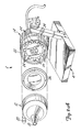
- Fig. 1 shows a perspective view of a centrifugal blood pump 2.
- Pump 2 is mounted on stand 4 (formed by base 6, support arm 8 and locking nut 10) and comprises a disposable pumping unit 12 and a magnetic drive device 14.
- Disposable pumping unit 12 is releasably connected to magnetic drive device 14.
- Electric cord 16 connects magnetic drive device 14 to an electric power source (not shown) and thereby provides electric excitation to magnetic drive device 14.
- blood enters disposable pumping unit 12 through inlet 18 and is pumped out through outlet 20.
- Figs. 2A and 2B are exploded views of the centrifugal pump shown in Fig. 1.
- Fig. 2A shows the centrifugal pump of Fig. 1 with disposable pumping unit 12 detached from magnetic drive means or device 14.
- the magnetic drive device 14 includes a rotor 22 having a plurality of circumferentially spaced drive magnets 24.
- a protective plate 26 is positioned adjacent the drive magnets 24 and is supported by the face of the magnetic drive device 14. The protective plate 26 isolates rotor 22 from foreign objects and contaminants which could impede the operation of magnetic drive device 14.
- the disposable pumping unit 12 comprises a pump housing (formed by housing cap 30 and housing base 32) enclosing a pumping chamber P therein (shown in Fig. 4).
- Housing cap 30 includes inlet 18 and outlet 20, and is preferably transparent so that operation of pump 2 can be visually monitored.
- the inlet 18 is aligned with a central axis C and the outlet 20 is positioned at the periphery of housing cap 30.
- An annular seal 34 is placed between housing cap 30 and housing base 32 to provide a fluid-tight seal for the pumping chamber P.
- the disposable pumping unit 12 also includes a stator 36 having a proximal end and a distal end.
- the proximal end is secured to housing base 32 and the distal end extends into the pumping chamber P.
- Stator 36 defines the central axis C and is generally conically shaped to reduce the stagnation of fluid near the central axis C.
- the stator 36 comprises two sections: a proximal section 38 and a distal section 40.
- Proximal section 38 is shaped as a frustal cone which can either be secured to or formed integral with housing base 32.
- Distal section 40 is cone shaped and secured to proximal section.
- Stator 36 in an alternate embodiment, can be formed as one piece.
- the word "stator” refers to a stationary member around which a rotating member, such as the impeller 44, can rotate.
- a bearing 42 is formed integrally with the distal end of the stator 36.
- the bearing 42 alternatively, can be formed separately and then secured to the distal end of the stator 36.
- the bearing 42 is shown as a ball-shaped pivot bearing but any one of a number of conventional bearing types could be employed.
- the bearing 42 is generally aligned with the central axis C.
- the bearing 42 is preferably made from a material having sufficient heat dissipation qualities, such as hard-coated aluminum.
- the distal section 40 of the stator 36 is also preferably made from material having good heat dissipation qualities. Heat dissipation is very important near the bearing 42 to protect both the bearing 42 and the blood being pumped through the pumping chamber P.
- a rotator or impeller 44 is positioned within the pumping chamber and is supported on bearing 42 for rotation about the central axis C.
- the impeller 44 is configured to have a generally conical shape.
- the impeller 44 has a hub 46 aligned with the central axis C for engagement with bearing 42.
- the impeller 44 includes long blades 48, short blades 50, and a circular flange 52.
- the long blades 48 are attached at their inner ends to the impeller hub 46.
- the flange 52 is attached to and is supported by the long blades 48.
- the short blades 50 are supported by the flange 52.
- the long and short blades 48 and 50 are alternately spaced about the circumference of the impeller 44.
- impellers require a greater number of blades in order to achieve pumping efficiency.
- the impeller 44 achieves pumping efficiency while retaining a small hub diameter, since only long blades 48 are attached to hub 46.
- openings are formed between adjacent long blades 48 that are believed to allow fluid to flow over the distal end 40 of the stator 36 and bearing 42.
- the impeller 44 carries magnetic means 59 (shown in Fig. 4) on or within flange 52 such that the magnetic means is axially displaced from bearing 42.
- Magnetic drive device 14 includes drive magnets 24 which communicate with magnetic means 59 carried by the flange 52 of the impeller 44 to rotate the impeller 44 within the pumping chamber P.
- the magnetic means 59 carried by the impeller 44 and the drive magnets 24 carried by rotor 22 must have enough attraction strength to achieve the desired operation of centrifugal blood pump 2. It is preferable to have drive magnets 24 be stronger than magnetic means 59 carried by the impeller 44 so that less expensive magnets may be used within the disposable pumping unit 12.
- Fig. 3 is a plan view of the disposable pumping unit 12 shown in Figs. 1, 2A and 2B.
- the transparent housing cap 30 is shown with the inlet 18 positioned along the central axis C and the outlet 20 positioned at the periphery.
- a tube 54 can be fitted to housing cap 30 at the outlet 20 for transferring fluid from the pumping chamber 56 to a destination.
- the impeller 44 is shown with long blades 48, short blades 50 and flange 52.
- Fig. 4 is a transverse section of the centrifugal pump 2 shown in Figs. 1, 2A and 2B.
- the centrifugal pump 2 comprises the disposable pumping unit 12 and the magnetic drive device 14.
- the disposable pumping unit 12 includes a housing cap 30 (with inlet 18), housing base 32, annular seal 34, stator 36, screw 58, and impeller 44.
- the stator 36 comprises a proximal section 38 and a distal section 40 which are secured together by a screw 58.
- the proximal section 38 is formed integrally with the housing base 32.
- the bearing 42 is formed integrally with the distal end of the stator 36, and supports the hub 46 of the impeller 44.
- the impeller 44 is shown carrying the magnetic means 59 on the flange 52.
- the magnetic means 59 is preferably a magnetic ring having a plurality of magnetic poles (not shown) and is commercially available. Alternatively, a plurality of circumferentially spaced magnets can be carried by the flange 52.
- the magnetic drive device 14 comprises a protective plate 26 and drive magnets 24 carried on the rotor 22.
- Fig. 4 also shows the positional relationship between the magnetic means 59 carried by the impeller 44 and the drive magnets 24 carried by the rotor 22.
- the magnetic lines of force F of the magnetic means 59 are substantially directed toward the bearing 42 and the central axis C.
- the drive magnets 24 are positioned such that their magnetic lines of force F generally align with and are parallel to the magnetic lines of force F generated by the magnetic means 59 carried by the impeller 44.
- the resulting unbalanced forces on the impeller 44 generally align with the central axis C and are in a direction from impeller hub 46 toward bearing 42. With this magnet orientation, the balanced forces stabilize rotation of the impeller 44 about the central axis C and hold the impeller 44 against the bearing 42.
- Fig. 5 shows an alternate embodiment of a disposable pumping unit 60 having a lower profile than shown in Fig. 4.
- This embodiment includes a pump housing 62, housing cap 64 with inlet 66, housing base 68, pumping chamber 70, impeller 72, and stator 74.
- the outlet of the housing 62 is not shown in Fig. 5, but is positioned similarly to outlet 20 shown in Fig. 1.
- Fig. 5 not only shows a low profile pumping unit, but also shows stator 74 as an alternate arrangement to stator 36 shown in Fig. 4.
- Stator 74 comprises a stator base 76 (formed integrally with the housing base 68) and a spindle 78, which generally replace bearing 42 and distal section 40 of stator 36.
- Spindle 78 has first and second opposite ends 78A and 78B.
- the first end 78A is secured to the stator base 76 of stator 74; and the second end 78B extends into the pumping chamber 70 and is rounded for use as a bearing (at 78B).
- the impeller 72 of figure 5 is similar to the impeller 44 described in Fig. 4 but it too has a lower profile.
- the impeller 72 has a different hub configuration 80 to accommodate the lower profile without sacrificing impeller blade area.
- the hub 80 is preferably made from hardcoated aluminum or similar heat dissipating material.
- the impeller 72 carries a magnetic means 82 on the flange 84 of the impeller 72 such that the magnetic lines of force F are generally directed toward the bearing at the second end 78B of the spindle 78 and the central axis C so that rotation of the impeller 72 is stabilized about the central axis C.
- the lower profile pumping unit 60 reduces the volume of the pumping chamber 70 while maintaining pumping efficiency. This reduces the amount of blood necessary to prime the pump before the start of operation.
- Fig. 6 shows another low profile disposable pumping unit embodiment 86.
- the pumping unit 86 comprises a stator 88, impeller 90, and pump housing 92.
- Pump housing 92 includes housing cap 94 and housing base 96.
- a ball-shaped pivot bearing 98 is used instead of the spindle of Fig. 5.
- the housing base 68 and stator 74 of Fig. 5 have been replaced with the housing base 96 and stator 88.
- the stator 88 has a similar configuration to stator 36 shown in Fig. 4 but has a lower profile.
- the stator 88 comprises a distal section 100, proximal section 102, and screw 104.
- the stator 88 defines central axis C.
- the impeller 90 is similar to the impeller 72 illustrated in Fig.
- the ball-shaped pivot bearing 98 is formed integrally with the distal section 100 of the stator 88, and the distal section 100 and bearing 98 are preferably formed of hardcoated aluminum or similar heat dissipating material.
- the pumping unit 86 of Fig. 6 is shown with an alternate bearing arrangement in the partial sectional view of Fig. 7.
- a convex bearing 112 is formed integrally with the hub 114 of the impeller 116.
- the convex bearing 112 rests on the concave bearing surface 117 of the distal section 119 of stator 118 for rotation about the central axis C.
- Distal section 116 is secured to proximal section 120 by screw 122.
- the convex bearing 112 can also be formed as a separate element and secured to the impeller hub (not shown).
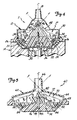
- Fig. 8 shows an alternate embodiment of a disposable pumping unit 124 having an alternate impeller configuration 126.
- the pumping unit 124 includes a pump housing 128, housing cap 130, housing base 132, inlet 134, an outlet (not shown) located at the periphery of housing 128, stator 136, and impeller 126.
- the stator 136 is similar to the stator 36 in Fig. 4 and comprises a proximal section 140, a distal section 142, and a screw 144.
- the impeller 126 comprises first and second concentric rotator cones 146 and 148 secured together with a plurality of struts 150.
- the first rotator cone 146 is supported by bearing 152 for rotation of the first and the second rotator cones 146 and 148 about central axis C.
- the first and second cones 146 and 148 each have an opening at the central axis C allowing fluid entering the pumping chamber 154 through the inlet 134 to increase heat dissipation by lubricating the bearing 152. This fluid flow path also limits the stagnation of fluid near the wall of the stator 136.
- the first rotator cone 146 carries a magnetic means 158 about its circumference and is oriented such that the magnetic lines of force F are substantially directed toward the bearing 152 and the central axis C.
- the invention provides a centrifugal blood pump having a minimal number of parts requiring disposal or sterilization.
- the drive shaft seals of prior centrifugal blood pumps have been eliminated, which increases reliability of the pump of this invention.
- Reliability is further increased by positioning the bearing, as shown in Fig. 4, near the inlet, and by providing openings through the impeller that direct blood flow along the bearing. This increases blood flow near the bearing and thereby reduces heat build-up on the bearing and on the blood near the surface of the bearing. Heat damage to the blood being pumped is therefore also reduced.
Abstract
Description
- The invention relates to centrifugal blood pumps, and in particular to a centrifugal blood pumping unit that is adapted to be releasably coupled to a magnetic drive device.
- Centrifugal pumps have been used for many years to pump a wide variety of different fluid materials. In general, a centrifugal pump includes a pump housing enclosing a pumping chamber therein, an inlet aligned with a rotational axis of the pump, an outlet adjacent the periphery of the pumping chamber, an impeller mounted within the pumping chamber for rotation about the axis, and a drive source communicating with the impeller. The impeller and drive source have several possible configurations. In one configuration, the impeller is mounted on a drive shaft which extends outside the pumping chamber to a rotational drive source. In another configuration, the pump housing encloses two chambers, one containing a magnetic rotor and the other containing the pumping chamber and impeller. The impeller and rotor are connected by a drive shaft. Seals are used to isolate the two chambers. A magnetic drive source communicates with the rotor to rotate the impeller within the pumping chamber. In still another configuration, the impeller is suspended within the pumping chamber by a magnetic means formed within the pump housing. Examples of these centrifugal pumps are shown in the following U.S. Patents: Kletschka et al. U.S. Pat. No. 3,864,055; Rafferty et al U.S. Pat. No. 3,647,324; and Olsen et al U.S. Pat. No. 4,688,998.
- In recent years, centrifugal pumps have been used extensively for pumping blood during open heart surgery. The pumping of blood requires great care to avoid any damage to the red corpuscles, or any of the other constituents of blood. Any practical blood pump useful as part of heart/lung bypass equipment during open heart surgery must deliver the requisite flow volumes under pressure, without damaging the blood being pumped.
- In many prior centrifugal pumps, and in particular in a centrifugal pump for pumping liquids such as blood, a fluid tight seal between the drive shaft and the housing is an important factor in the performance of the pump. Friction at the seal produces heat which, if not dissipated, can damage both the components of the pump and the blood being pumped. Also, the rotation of the impeller can lead to generation of an air bubble surrounding the shaft. This air bubble tends to seek the smallest shaft diameter, which typically is adjacent the drive shaft seal. In some of the prior art pumps, the area adjacent the drive shaft seal has also been a relatively stagnant or low flow area in terms of fluid flow within the pumping chamber. The air bubble tends to insulate the seal from the flow of the fluid within the pumping chamber, thus decreasing the dissipation of heat generated by friction at the seal surface.
- It is often the case that blood pumps are used only once. After a single use, the portions of the pump which contact the blood must either be disposed of or its constituent parts must be sterilized. A centrifugal blood pump comprising a minimal number of parts is desirable to reduce costs and improve reliability.
- U.S. Patent Nos. 4,507,048; 4,589,822; 4,606,698; 4,643,641 and 4,898,518 describe various centrifugal blood pumps.
- Additional examples of centrifugal pumps are shown in U.S. Patent Nos. 3,354,833; 3,411,450; 3,645,650; 3,771,910; 3,762,839; 3,838,947 and 4,352,646, as well as in Japanese Kokoku No. 43(1968)/17206 and German Offenlegungsschrift Nos. 1,728,462 and 2,048,286. The Japanese Kokoku No. 43/17206 describes a centrifugal pump in which a pump runner is magnetically coupled with a group of drive magnets. The pump runner is positioned within a pump housing, and rotatable about a pivot or thrust bearing supported by struts near the inlet of the pump housing. The pump runner carries a group of magnets that are driven by the drive magnets. When rotation of the drive magnets of that pump is stopped, the pump runner contacts the bottom plate due to the force of attraction between the drive and driven magnets, and a gap is formed between the pivot bearing and the runner.
- According to the invention, an improved centrifugal pumping unit is provided for pumping biological fluid, such as blood, and which is disposable after one use. The pumping unit is adapted to be releasably mounted on a magnetic drive means.
- Generally, the pumping unit comprises a pump housing enclosing a pumping chamber therein, a bearing supported in the pumping chamber, and an impeller positioned within the pumping chamber. The pump housing has an inlet and an outlet communicating with the pumping chamber. The impeller is supported at its hub by the bearing for rotation about a central axis defined by the bearing. A plurality of openings, which are configured to expose the bearing to fluid, are provided in the impeller. A magnetic means (e.g., at least one magnet) is carried by the impeller, and is adapted to be magnetically coupled with the magnetic drive means to rotate the impeller, thereby pumping fluid through the pumping unit..
- In one preferred embodiment, the bearing is a ball-shaped pivot bearing made, for example, from hardcoated aluminum to provide sufficient heat dissipation. The impeller carries an annular magnetic ring about its circumference. The magnetic ring has a plurality of magnetic poles and is positioned such that the magnetic lines of force are substantially directed toward the bearing and the central axis. The resulting unbalanced forces on the impeller hub are generally parallel to the central axis in a "downward" direction from the hub toward the bearing, therefore stabilizing the rotation of the impeller about the central axis.
- The centrifugal pump preferably includes a magnetic drive device releasably connected to the disposable pumping unit. The magnetic drive device includes a rotor having a plurality of drive magnets spaced annularly about its circumference. The drive magnets are positioned such that their magnetic lines of force align with and are generally parallel to the magnetic lines of force of the magnetic ring carried by the impeller within the pumping chamber. The drive magnets communicate with the magnetic ring carried by the impeller, and thereby rotate the impeller within the pumping chamber as the rotor of the magnetic drive device is rotated.
-
- Fig. 1 is a perspective view of a centrifugal blood pump of the present invention.
- Fig. 2A is an exploded view of the pump of Fig. 1 showing the disposable pumping unit detached from the magnetic drive device.
- Fig. 2B is an exploded view of the centrifugal blood pump of Figs. 1 and 2A.
- Fig. 3 is a plan view of the pumping unit of Figs. 1, 2A and 2B removed from the magnetic drive means.
- Fig. 4 is a transverse section of the pump taken along line 4-4 of Fig. 3 and includes the magnetic drive device of Figs. 1, 2A and 2B.
- Fig. 5 is a view similar to Fig. 4 of an alternate embodiment having a low profile and an alternate stator arrangement.
- Fig. 6 is an alternate embodiment having a low profile and stator arrangement similar to the one shown in Fig. 4.
- Fig. 7 is a fragmentary detail of an alternate bearing arrangement.
- Fig. 8 is a partial sectional view of an embodiment with an alternate impeller arrangement.
- Figs. 1-4 show one embodiment of the centrifugal blood pump of the invention. Figs. 5-8 illustrate alternate embodiments.
- Fig. 1 shows a perspective view of a centrifugal blood pump 2. Pump 2 is mounted on stand 4 (formed by base 6,
support arm 8 and locking nut 10) and comprises adisposable pumping unit 12 and amagnetic drive device 14.Disposable pumping unit 12 is releasably connected tomagnetic drive device 14.Electric cord 16 connectsmagnetic drive device 14 to an electric power source (not shown) and thereby provides electric excitation tomagnetic drive device 14. During pump operation, blood entersdisposable pumping unit 12 throughinlet 18 and is pumped out throughoutlet 20. - Figs. 2A and 2B are exploded views of the centrifugal pump shown in Fig. 1. Fig. 2A shows the centrifugal pump of Fig. 1 with
disposable pumping unit 12 detached from magnetic drive means ordevice 14. Themagnetic drive device 14 includes arotor 22 having a plurality of circumferentially spaceddrive magnets 24. Aprotective plate 26 is positioned adjacent thedrive magnets 24 and is supported by the face of themagnetic drive device 14. Theprotective plate 26isolates rotor 22 from foreign objects and contaminants which could impede the operation ofmagnetic drive device 14. - As shown in Fig. 2B, the
disposable pumping unit 12 comprises a pump housing (formed byhousing cap 30 and housing base 32) enclosing a pumping chamber P therein (shown in Fig. 4).Housing cap 30 includesinlet 18 andoutlet 20, and is preferably transparent so that operation of pump 2 can be visually monitored. Theinlet 18 is aligned with a central axis C and theoutlet 20 is positioned at the periphery ofhousing cap 30. Anannular seal 34 is placed betweenhousing cap 30 andhousing base 32 to provide a fluid-tight seal for the pumping chamber P. - The
disposable pumping unit 12 also includes astator 36 having a proximal end and a distal end. The proximal end is secured tohousing base 32 and the distal end extends into the pumpingchamber P. Stator 36 defines the central axis C and is generally conically shaped to reduce the stagnation of fluid near the central axis C. Thestator 36 comprises two sections: aproximal section 38 and adistal section 40.Proximal section 38 is shaped as a frustal cone which can either be secured to or formed integral withhousing base 32.Distal section 40 is cone shaped and secured to proximal section.Stator 36, in an alternate embodiment, can be formed as one piece. As used herein the word "stator" refers to a stationary member around which a rotating member, such as theimpeller 44, can rotate. - A
bearing 42 is formed integrally with the distal end of thestator 36. Thebearing 42, alternatively, can be formed separately and then secured to the distal end of thestator 36. Thebearing 42 is shown as a ball-shaped pivot bearing but any one of a number of conventional bearing types could be employed. Thebearing 42 is generally aligned with the central axis C. Thebearing 42 is preferably made from a material having sufficient heat dissipation qualities, such as hard-coated aluminum. Thedistal section 40 of thestator 36 is also preferably made from material having good heat dissipation qualities. Heat dissipation is very important near the bearing 42 to protect both thebearing 42 and the blood being pumped through the pumping chamber P. - A rotator or
impeller 44 is positioned within the pumping chamber and is supported on bearing 42 for rotation about the central axis C. In this embodiment, theimpeller 44 is configured to have a generally conical shape. Theimpeller 44 has ahub 46 aligned with the central axis C for engagement withbearing 42. Theimpeller 44 includeslong blades 48,short blades 50, and acircular flange 52. Thelong blades 48 are attached at their inner ends to theimpeller hub 46. Theflange 52 is attached to and is supported by thelong blades 48. Theshort blades 50 are supported by theflange 52. In the particular embodiment shown in Figures 2A and 2B, the long andshort blades impeller 44. Large diameter impellers require a greater number of blades in order to achieve pumping efficiency. By use ofshort blades 50 supported byflange 52, theimpeller 44 achieves pumping efficiency while retaining a small hub diameter, since onlylong blades 48 are attached tohub 46. As shown in figure 2B, openings are formed between adjacentlong blades 48 that are believed to allow fluid to flow over thedistal end 40 of thestator 36 andbearing 42. Theimpeller 44 carries magnetic means 59 (shown in Fig. 4) on or withinflange 52 such that the magnetic means is axially displaced from bearing 42. -
Magnetic drive device 14 includesdrive magnets 24 which communicate withmagnetic means 59 carried by theflange 52 of theimpeller 44 to rotate theimpeller 44 within the pumping chamber P. The magnetic means 59 carried by theimpeller 44 and thedrive magnets 24 carried byrotor 22 must have enough attraction strength to achieve the desired operation of centrifugal blood pump 2. It is preferable to havedrive magnets 24 be stronger thanmagnetic means 59 carried by theimpeller 44 so that less expensive magnets may be used within thedisposable pumping unit 12. - Fig. 3 is a plan view of the
disposable pumping unit 12 shown in Figs. 1, 2A and 2B. Thetransparent housing cap 30 is shown with theinlet 18 positioned along the central axis C and theoutlet 20 positioned at the periphery. Atube 54 can be fitted tohousing cap 30 at theoutlet 20 for transferring fluid from the pumpingchamber 56 to a destination. Theimpeller 44 is shown withlong blades 48,short blades 50 andflange 52. - Fig. 4 is a transverse section of the centrifugal pump 2 shown in Figs. 1, 2A and 2B. The centrifugal pump 2 comprises the
disposable pumping unit 12 and themagnetic drive device 14. Thedisposable pumping unit 12 includes a housing cap 30 (with inlet 18),housing base 32,annular seal 34,stator 36,screw 58, andimpeller 44. Thestator 36 comprises aproximal section 38 and adistal section 40 which are secured together by ascrew 58. In this embodiment, theproximal section 38 is formed integrally with thehousing base 32. Thebearing 42 is formed integrally with the distal end of thestator 36, and supports thehub 46 of theimpeller 44. Theimpeller 44 is shown carrying the magnetic means 59 on theflange 52. The magnetic means 59 is preferably a magnetic ring having a plurality of magnetic poles (not shown) and is commercially available. Alternatively, a plurality of circumferentially spaced magnets can be carried by theflange 52. Themagnetic drive device 14 comprises aprotective plate 26 and drivemagnets 24 carried on therotor 22. - Fig. 4 also shows the positional relationship between the magnetic means 59 carried by the
impeller 44 and thedrive magnets 24 carried by therotor 22. The magnetic lines of force F of the magnetic means 59 are substantially directed toward thebearing 42 and the central axis C. Thedrive magnets 24 are positioned such that their magnetic lines of force F generally align with and are parallel to the magnetic lines of force F generated by the magnetic means 59 carried by theimpeller 44. The resulting unbalanced forces on theimpeller 44 generally align with the central axis C and are in a direction fromimpeller hub 46 towardbearing 42. With this magnet orientation, the balanced forces stabilize rotation of theimpeller 44 about the central axis C and hold theimpeller 44 against thebearing 42. - Fig. 5 shows an alternate embodiment of a
disposable pumping unit 60 having a lower profile than shown in Fig. 4. This embodiment includes apump housing 62,housing cap 64 withinlet 66, housing base 68, pumpingchamber 70,impeller 72, andstator 74. The outlet of thehousing 62 is not shown in Fig. 5, but is positioned similarly tooutlet 20 shown in Fig. 1. Fig. 5 not only shows a low profile pumping unit, but also showsstator 74 as an alternate arrangement to stator 36 shown in Fig. 4.Stator 74 comprises a stator base 76 (formed integrally with the housing base 68) and aspindle 78, which generally replacebearing 42 anddistal section 40 ofstator 36.Spindle 78 has first and second opposite ends 78A and 78B. Thefirst end 78A is secured to thestator base 76 ofstator 74; and thesecond end 78B extends into the pumpingchamber 70 and is rounded for use as a bearing (at 78B). - The
impeller 72 of figure 5 is similar to theimpeller 44 described in Fig. 4 but it too has a lower profile. Theimpeller 72 has adifferent hub configuration 80 to accommodate the lower profile without sacrificing impeller blade area. Thehub 80 is preferably made from hardcoated aluminum or similar heat dissipating material. Theimpeller 72 carries a magnetic means 82 on theflange 84 of theimpeller 72 such that the magnetic lines of force F are generally directed toward the bearing at thesecond end 78B of thespindle 78 and the central axis C so that rotation of theimpeller 72 is stabilized about the central axis C. The lowerprofile pumping unit 60 reduces the volume of the pumpingchamber 70 while maintaining pumping efficiency. This reduces the amount of blood necessary to prime the pump before the start of operation. - Fig. 6 shows another low profile disposable
pumping unit embodiment 86. Thepumping unit 86 comprises astator 88, impeller 90, and pumphousing 92.Pump housing 92 includeshousing cap 94 andhousing base 96. A ball-shaped pivot bearing 98 is used instead of the spindle of Fig. 5. The housing base 68 andstator 74 of Fig. 5 have been replaced with thehousing base 96 andstator 88. Thestator 88 has a similar configuration to stator 36 shown in Fig. 4 but has a lower profile. Thestator 88 comprises adistal section 100,proximal section 102, and screw 104. Thestator 88 defines central axis C. The impeller 90 is similar to theimpeller 72 illustrated in Fig. 5 and includes ahub 106,flange 108, andmagnetic means 110. The magnetic means 110 creates magnetic lines of force F. In this embodiment, the ball-shaped pivot bearing 98 is formed integrally with thedistal section 100 of thestator 88, and thedistal section 100 and bearing 98 are preferably formed of hardcoated aluminum or similar heat dissipating material. - The
pumping unit 86 of Fig. 6 is shown with an alternate bearing arrangement in the partial sectional view of Fig. 7. A convex bearing 112 is formed integrally with the hub 114 of theimpeller 116. The convex bearing 112 rests on the concave bearing surface 117 of the distal section 119 ofstator 118 for rotation about the central axisC. Distal section 116 is secured to proximal section 120 byscrew 122. The convex bearing 112 can also be formed as a separate element and secured to the impeller hub (not shown). - Fig. 8 shows an alternate embodiment of a
disposable pumping unit 124 having an alternate impeller configuration 126. Thepumping unit 124 includes a pump housing 128,housing cap 130,housing base 132,inlet 134, an outlet (not shown) located at the periphery of housing 128,stator 136, and impeller 126. Thestator 136 is similar to thestator 36 in Fig. 4 and comprises aproximal section 140, adistal section 142, and ascrew 144. The impeller 126 comprises first and secondconcentric rotator cones struts 150. Thefirst rotator cone 146 is supported by bearing 152 for rotation of the first and thesecond rotator cones second cones pumping chamber 154 through theinlet 134 to increase heat dissipation by lubricating thebearing 152. This fluid flow path also limits the stagnation of fluid near the wall of thestator 136. Thefirst rotator cone 146 carries amagnetic means 158 about its circumference and is oriented such that the magnetic lines of force F are substantially directed toward thebearing 152 and the central axis C. - The invention provides a centrifugal blood pump having a minimal number of parts requiring disposal or sterilization. The drive shaft seals of prior centrifugal blood pumps have been eliminated, which increases reliability of the pump of this invention. Reliability is further increased by positioning the bearing, as shown in Fig. 4, near the inlet, and by providing openings through the impeller that direct blood flow along the bearing. This increases blood flow near the bearing and thereby reduces heat build-up on the bearing and on the blood near the surface of the bearing. Heat damage to the blood being pumped is therefore also reduced.
- The reduced parts count of the disposable pumping unit along with its simplistic design lowers the relative cost of centrifugal blood pumps with respect to prior centrifugal blood pumps.
- Although the present invention has been described with reference to preferred embodiments, workers skilled in the art will recognize that changes may be made in form and detail without departing from the spirit and scope of the invention.
Claims (11)
a pump housing (30 and 32; 62; 92; 128) having a pumping chamber (P; 70) therein, and an inlet (18; 66; 134) and an outlet (20) communicating with the pumping chamber (P; 70);
a bearing (42; 78B; 98; 152) supported in the pumping chamber (P; 70);
an impeller (44; 72; 90; 126) positioned within the pumping chamber (P; 70), the impeller (44; 72; 90; 126) having a hub (46; 80; 106) rotatably supported on the bearing (42; 78B; 98; 152) for rotation about a central axis (C) and having a plurality of openings configured to expose the bearing (42; 78B; 98; 152) to the fluid; and
magnetic means (59; 82; 110; 158) carried by the impeller (44; 72; 90; 126) within the pumping chamber (P; 70) adapted to be magnetically coupled with a magnetic drive means (14) to rotate the impeller (44; 72; 90; 126), and thereby pump fluid through the pumping unit (12; 60; 86; 124).
a disposable pumping unit (12; 60; 86; 124) comprising:
a pump housing (30 and 32; 62; 92; 128) having a pumping chamber (P; 70) therein, and having an inlet (18; 66; 134) and an outlet (20) communicating with the pumping chamber (P; 70);
a bearing (42; 78B; 98; 152) supported in the pumping chamber (P; 70), the bearing (42; 78B; 98; 152) defining a central axis (C);
an impeller (44; 72; 90; 126) positioned within the pumping chamber (P; 70) and supported on the bearing (42; 78B; 98; 152) for rotation about the central axis (C), the impeller (44; 72; 90; 126) having a hub (46; 80; 106) and a plurality of openings configured to expose the bearing (42; 78B; 98; 152) to the fluid; and
magnetic means (59; 82; 110; 158) carried by the impeller (44; 72; 90; 126); and
magnetic drive means (14) for releasable connection to the pump housing (32; 62; 92; 128) to communicate with the magnetic means (59; 82; 110; 158) carried by the impeller (44; 72; 90; 126) and thereby to rotate the impeller (44; 72; 90; 126) within the pumping chamber (P; 70).
a rotor (22) positioned adjacent the pump housing (32; 62; 92; 128); and
a plurality of drive magnets (24) annularly spaced about the circumference of the rotor (22) and oriented with the magnetic lines of force (F) generated by the drive magnets (24) aligning with the magnetic lines of force (F) generated by the magnetic means (59; 82; 110; 158) carried by the impeller (44; 72; 90; 126) and intersecting the central axis (C) such that resulting unbalanced forces on the impeller hub (46; 80; 106) are in a direction tending to urge the impeller hub (46; 80; 106) toward the bearing (42; 78B; 98; 152), the resulting unbalanced forces being generally parallel to the central axis (C) thereby stabilizing the rotation of the impeller (44; 72; 90; 126) about the bearing (42; 78B; 98; 152) and the central axis (C).
a housing cap (30; 64; 94; 130) having the inlet (18; 66) aligned with the central axis (C) for routing fluid into the pumping chamber (P; 70);
a housing base (32; 68; 96; 132) secured to the housing cap (30; 64; 94; 130) thereby enclosing the pumping chamber (P; 70) therein; and
an annular fluid-tight seal (34) between the housing cap (30; 64; 94; 130) and base (32; 68; 96; 132).
a stator base (76) shaped as a frustal cone with a trapezoidal cross-section along the central axis (C), the stator base (76) having a maximum radial dimension and a minimum radial dimension, the maximum radial dimension defining the proximal end of the stator (74); and
a spindle (78) having first and second opposite ends (78A and 78B) aligned with the central axis (C), the first end (78A) attached to the minimum radial dimension of the stator base (76) and the second end (78B) defining the distal end (78B) of the stator (74);
the bearing (78B) being integrally formed with the second end (78B) of the spindle (78) in alignment with the central axis (C). (Figure 5)
Applications Claiming Priority (2)
| Application Number | Priority Date | Filing Date | Title |
|---|---|---|---|
| US07/426,102 US4984972A (en) | 1989-10-24 | 1989-10-24 | Centrifugal blood pump |
| US426102 | 1989-10-24 |
Publications (3)
| Publication Number | Publication Date |
|---|---|
| EP0425257A2 true EP0425257A2 (en) | 1991-05-02 |
| EP0425257A3 EP0425257A3 (en) | 1991-07-24 |
| EP0425257B1 EP0425257B1 (en) | 1994-11-30 |
Family
ID=23689298
Family Applications (1)
| Application Number | Title | Priority Date | Filing Date |
|---|---|---|---|
| EP90311634A Expired - Lifetime EP0425257B1 (en) | 1989-10-24 | 1990-10-24 | Centrifugal blood pump |
Country Status (6)
| Country | Link |
|---|---|
| US (1) | US4984972A (en) |
| EP (1) | EP0425257B1 (en) |
| JP (1) | JP3012308B2 (en) |
| AU (1) | AU628676B2 (en) |
| CA (1) | CA2028257A1 (en) |
| DE (1) | DE69014552T2 (en) |
Cited By (6)
| Publication number | Priority date | Publication date | Assignee | Title |
|---|---|---|---|---|
| DE4430853A1 (en) * | 1994-08-31 | 1996-03-07 | Jostra Medizintechnik | Centrifugal blood pump |
| EP1013294A1 (en) * | 1998-12-16 | 2000-06-28 | Sulzer Electronics AG | Diagonal flux pump |
| EP1186310A1 (en) * | 2000-09-11 | 2002-03-13 | JMS Co., Ltd. | Turbo blood pump |
| EP1188453A1 (en) * | 2000-09-14 | 2002-03-20 | JMS Co., Ltd. | Turbo blood pump |
| AT412065B (en) * | 2000-03-24 | 2004-09-27 | Schima Heinrich Dr | ROTATIONAL PUMP WITH HYDRAULICALLY BEARED ROTOR |
| WO2012034569A3 (en) * | 2010-09-18 | 2012-10-26 | Juriqa Holding Aps | Portable centrifugal blood pump |
Families Citing this family (93)
| Publication number | Priority date | Publication date | Assignee | Title |
|---|---|---|---|---|
| JPH03228039A (en) * | 1989-11-16 | 1991-10-09 | Fuji Photo Film Co Ltd | Electromagnetic driving device for diaphragm |
| US5112202A (en) * | 1990-01-31 | 1992-05-12 | Ntn Corporation | Turbo pump with magnetically supported impeller |
| US5211546A (en) * | 1990-05-29 | 1993-05-18 | Nu-Tech Industries, Inc. | Axial flow blood pump with hydrodynamically suspended rotor |
| IT1243345B (en) * | 1990-07-16 | 1994-06-10 | Dideco Spa | CENTRIFUGAL PUMP FOR LIQUID, IN PARTICULAR BLOOD IN EXTRA-BODY CIRCULATION |
| US5171212A (en) * | 1991-02-08 | 1992-12-15 | Minnesota Mining And Manufacturing Company | Blood pumping system with backflow warning |
| IT1245466B (en) * | 1991-03-19 | 1994-09-20 | Iveco Fiat | ELECTRIC PUMP FOR THE CIRCULATION OF A LIQUID, FOR EXAMPLE IN AN INTERNAL COMBUSTION ENGINE |
| US5316440A (en) * | 1991-05-10 | 1994-05-31 | Terumo Kabushiki Kaisha | Blood pump apparatus |
| EP0518050B1 (en) * | 1991-05-10 | 1996-07-10 | Terumo Kabushiki Kaisha | Liquid pump apparatus |
| US5350283A (en) * | 1991-12-04 | 1994-09-27 | Ntn Corporation | Clean pump |
| EP0653022B1 (en) * | 1992-07-30 | 2001-12-05 | Cobe Cardiovascular, Inc. | Centrifugal blood pump |
| JPH0669492B2 (en) * | 1992-08-20 | 1994-09-07 | 日機装株式会社 | Blood pump |
| US5399074A (en) * | 1992-09-04 | 1995-03-21 | Kyocera Corporation | Motor driven sealless blood pump |
| US5713730A (en) * | 1992-09-04 | 1998-02-03 | Kyocera Corporation | Ceramic pivot bearing arrangement for a sealless blood pump |
| US5376114A (en) * | 1992-10-30 | 1994-12-27 | Jarvik; Robert | Cannula pumps for temporary cardiac support and methods of their application and use |
| JP2569419B2 (en) * | 1993-02-18 | 1997-01-08 | 工業技術院長 | Artificial heart pump |
| DE4321260C1 (en) * | 1993-06-25 | 1995-03-09 | Westphal Dieter Dipl Ing Dipl | Blood pump as a centrifugal pump |
| WO1995009984A1 (en) * | 1993-10-07 | 1995-04-13 | Haemonetics Corporation | Centrifugal blood pump with impeller blades forming a spin inducer |
| US5527159A (en) * | 1993-11-10 | 1996-06-18 | The United States Of America As Represented By The Administrator Of The National Aeronautics And Space Administration | Rotary blood pump |
| US5947892A (en) * | 1993-11-10 | 1999-09-07 | Micromed Technology, Inc. | Rotary blood pump |
| US5851174A (en) * | 1996-09-17 | 1998-12-22 | Robert Jarvik | Cardiac support device |
| JP4016441B2 (en) * | 1996-10-02 | 2007-12-05 | 株式会社ジェイ・エム・エス | Turbo blood pump |
| WO1998014225A2 (en) | 1996-10-04 | 1998-04-09 | United States Surgical Corporation | Circulatory support system |
| US6071093A (en) * | 1996-10-18 | 2000-06-06 | Abiomed, Inc. | Bearingless blood pump and electronic drive system |
| US6048363A (en) * | 1997-05-13 | 2000-04-11 | Nagyszalanczy; Lorant | Centrifugal blood pump apparatus |
| US5976388A (en) * | 1997-05-20 | 1999-11-02 | Cobe Cardiovascular Operating Co., Inc. | Method and apparatus for autologous blood salvage |
| US5919125A (en) * | 1997-07-11 | 1999-07-06 | Cobe Laboratories, Inc. | Centrifuge bowl for autologous blood salvage |
| US6123725A (en) * | 1997-07-11 | 2000-09-26 | A-Med Systems, Inc. | Single port cardiac support apparatus |
| US7182727B2 (en) * | 1997-07-11 | 2007-02-27 | A—Med Systems Inc. | Single port cardiac support apparatus |
| DE59712162D1 (en) * | 1997-09-04 | 2005-02-17 | Levitronix Llc Waltham | centrifugal pump |
| DE59710092D1 (en) * | 1997-09-25 | 2003-06-18 | Levitronix Llc Waltham | Centrifugal pump and centrifugal pump arrangement |
| JPH11244376A (en) | 1998-02-27 | 1999-09-14 | Kyocera Corp | Blood pump |
| US6152704A (en) * | 1998-09-30 | 2000-11-28 | A-Med Systems, Inc. | Blood pump with turbine drive |
| US6210133B1 (en) | 1998-09-30 | 2001-04-03 | A-Med Systems, Inc. | Blood pump with sterile motor housing |
| US6416215B1 (en) | 1999-12-14 | 2002-07-09 | University Of Kentucky Research Foundation | Pumping or mixing system using a levitating magnetic element |
| US6245007B1 (en) | 1999-01-28 | 2001-06-12 | Terumo Cardiovascular Systems Corporation | Blood pump |
| US6758593B1 (en) | 2000-10-09 | 2004-07-06 | Levtech, Inc. | Pumping or mixing system using a levitating magnetic element, related system components, and related methods |
| US7884522B1 (en) | 2004-10-25 | 2011-02-08 | Novatorque, Inc. | Stator and rotor-stator structures for electrodynamic machines |
| US6746416B2 (en) | 2001-12-05 | 2004-06-08 | Spin Corporation | Duplex blood pump for heart surgery |
| CA2374989A1 (en) * | 2002-03-08 | 2003-09-08 | Andre Garon | Ventricular assist device comprising a dual inlet hybrid flow blood pump |
| ITMI20030647A1 (en) * | 2003-04-01 | 2004-10-02 | Dideco Spa | DEVICE FOR THE TREATMENT OF BLOOD IN EXTRACORPOREA CIRCULATION |
| CA2428741A1 (en) * | 2003-05-13 | 2004-11-13 | Cardianove Inc. | Dual inlet mixed-flow blood pump |
| DE10336902C5 (en) | 2003-08-08 | 2019-04-25 | Abiomed Europe Gmbh | Intracardiac pumping device |
| US7416525B2 (en) * | 2003-09-18 | 2008-08-26 | Myrakelle, Llc | Rotary blood pump |
| US7014605B2 (en) * | 2004-04-15 | 2006-03-21 | Paul Weatherbee | Pulsatile blood pumping system |
| US7982350B2 (en) | 2004-10-25 | 2011-07-19 | Novatorque, Inc. | Conical magnets and rotor-stator structures for electrodynamic machines |
| US8283832B2 (en) * | 2004-10-25 | 2012-10-09 | Novatorque, Inc. | Sculpted field pole members and methods of forming the same for electrodynamic machines |
| US7294948B2 (en) * | 2004-10-25 | 2007-11-13 | Novatorque, Inc. | Rotor-stator structure for electrodynamic machines |
| US7061152B2 (en) * | 2004-10-25 | 2006-06-13 | Novatorque, Inc. | Rotor-stator structure for electrodynamic machines |
| US8471425B2 (en) | 2011-03-09 | 2013-06-25 | Novatorque, Inc. | Rotor-stator structures including boost magnet structures for magnetic regions having angled confronting surfaces in rotor assemblies |
| US8330316B2 (en) | 2011-03-09 | 2012-12-11 | Novatorque, Inc. | Rotor-stator structures including boost magnet structures for magnetic regions in rotor assemblies disposed external to boundaries of conically-shaped spaces |
| US9093874B2 (en) | 2004-10-25 | 2015-07-28 | Novatorque, Inc. | Sculpted field pole members and methods of forming the same for electrodynamic machines |
| US8543365B1 (en) | 2004-10-25 | 2013-09-24 | Novatorque, Inc. | Computer-readable medium, a method and an apparatus for designing and simulating electrodynamic machines implementing conical and cylindrical magnets |
| JP4496376B2 (en) * | 2005-09-05 | 2010-07-07 | 国立大学法人東京工業大学 | Disposable magnetic levitation blood pump |
| US20070231135A1 (en) | 2006-03-31 | 2007-10-04 | Orqis Medical Corporation | Rotary Blood Pump |
| JP4548450B2 (en) * | 2007-05-29 | 2010-09-22 | 株式会社ジェイ・エム・エス | Turbo blood pump |
| US8489190B2 (en) | 2007-10-08 | 2013-07-16 | Ais Gmbh Aachen Innovative Solutions | Catheter device |
| US8439859B2 (en) | 2007-10-08 | 2013-05-14 | Ais Gmbh Aachen Innovative Solutions | Catheter device |
| EP2194278A1 (en) | 2008-12-05 | 2010-06-09 | ECP Entwicklungsgesellschaft mbH | Fluid pump with a rotor |
| WO2010083282A1 (en) * | 2009-01-15 | 2010-07-22 | The Charles Stark Draper Laboratory, Inc. | High-throughput biological screening |
| JP5267227B2 (en) * | 2009-03-09 | 2013-08-21 | 株式会社ジェイ・エム・エス | Turbo blood pump |
| US8366418B2 (en) | 2009-06-12 | 2013-02-05 | Gulfstream, Inc. | Magnetic centrifugal pump |
| EP2273124B1 (en) * | 2009-07-06 | 2015-02-25 | Levitronix GmbH | Centrifugal pump and method for compensating for the axial impulse in a centrifugal pump |
| CN102667167A (en) * | 2010-02-02 | 2012-09-12 | 三菱重工业株式会社 | Centrifugal pump |
| US9662431B2 (en) | 2010-02-17 | 2017-05-30 | Flow Forward Medical, Inc. | Blood pump systems and methods |
| WO2011103356A1 (en) | 2010-02-17 | 2011-08-25 | Novita Therapeutics, Llc | System and method to increase the overall diameter of veins |
| US9555174B2 (en) | 2010-02-17 | 2017-01-31 | Flow Forward Medical, Inc. | Blood pump systems and methods |
| DE102010024650A1 (en) | 2010-05-04 | 2011-11-10 | Medos Medizintechnik Ag | Blood pump with a rotor |
| EP2388029A1 (en) | 2010-05-17 | 2011-11-23 | ECP Entwicklungsgesellschaft mbH | Pump array |
| EP2399639A1 (en) | 2010-06-25 | 2011-12-28 | ECP Entwicklungsgesellschaft mbH | System for introducing a pump |
| EP2407186A1 (en) | 2010-07-15 | 2012-01-18 | ECP Entwicklungsgesellschaft mbH | Rotor for a pump, produced with an initial elastic material |
| JP5623203B2 (en) * | 2010-09-08 | 2014-11-12 | テルモ株式会社 | Centrifugal blood pump and centrifugal blood pump device |
| US9227001B2 (en) | 2010-10-07 | 2016-01-05 | Everheart Systems Inc. | High efficiency blood pump |
| WO2012108475A1 (en) * | 2011-02-10 | 2012-08-16 | 三菱重工業株式会社 | Pump configuration |
| RU2664156C2 (en) | 2011-08-17 | 2018-08-15 | Флоу Форвард Медикал, Инк., Сша | System and method for increase of outer diameter of viens and arteries |
| KR102215188B1 (en) | 2011-08-17 | 2021-02-17 | 아르티오 메디컬 인크. | Blood pump systems and methods |
| EP2606920A1 (en) | 2011-12-22 | 2013-06-26 | ECP Entwicklungsgesellschaft mbH | Sluice device for inserting a catheter |
| EP2606919A1 (en) | 2011-12-22 | 2013-06-26 | ECP Entwicklungsgesellschaft mbH | Sluice device for inserting a catheter |
| US9511178B2 (en) | 2012-07-09 | 2016-12-06 | Medtronic, Inc. | Reducing centrifugal pump bearing wear through dynamic magnetic coupling |
| US10258730B2 (en) | 2012-08-17 | 2019-04-16 | Flow Forward Medical, Inc. | Blood pump systems and methods |
| EP2745869A1 (en) | 2012-12-21 | 2014-06-25 | ECP Entwicklungsgesellschaft mbH | Sluice assembly for the introduction of a cord-like body, in particular of a catheter, into a patient |
| US10294944B2 (en) | 2013-03-08 | 2019-05-21 | Everheart Systems Inc. | Flow thru mechanical blood pump bearings |
| JP6446212B2 (en) * | 2014-09-12 | 2018-12-26 | 泉工医科工業株式会社 | Drive device for centrifugal blood pump |
| WO2017190155A2 (en) | 2016-04-29 | 2017-11-02 | Flow Forward Medical, Inc. | Conduit tips and systems and methods for use |
| CN107296988A (en) * | 2017-06-19 | 2017-10-27 | 广东顺德工业设计研究院(广东顺德创新设计研究院) | On-bladed blood pump |
| CN107126588B (en) * | 2017-06-19 | 2018-09-14 | 广东顺德工业设计研究院(广东顺德创新设计研究院) | On-bladed blood pump with buffer layer |
| EP3574932A1 (en) * | 2018-05-28 | 2019-12-04 | Berlin Heart GmbH | Blood pump |
| WO2020255499A1 (en) * | 2019-06-19 | 2020-12-24 | テルモ株式会社 | Pump device |
| CN111249551B (en) * | 2020-01-21 | 2020-11-24 | 深圳汉诺医疗创新技术有限公司 | Worm type pump head for artificial heart, artificial heart pump and ECMO equipment |
| EP3854447A1 (en) * | 2020-01-21 | 2021-07-28 | Chinabridge (Shenzen) Medical Technology Co., Ltd. | Centrifugal blood pump |
| DE102020117818A1 (en) * | 2020-07-07 | 2022-01-13 | Resuscitec Gmbh | blood pump |
| CN112494804B (en) * | 2020-11-23 | 2023-09-19 | 苏州恒瑞宏远医疗科技有限公司 | Driving turntable and device suitable for magnetic driving centrifugal blood pump |
| CN112546423A (en) * | 2020-12-02 | 2021-03-26 | 深圳汉诺医疗科技有限公司 | Extracorporeal membrane oxygenation pump driving device |
| CN114165456B (en) * | 2021-12-17 | 2022-10-28 | 浙江大学 | Centrifugal pump based on magnetic-liquid double-suspension structure |
Citations (6)
| Publication number | Priority date | Publication date | Assignee | Title |
|---|---|---|---|---|
| US3411450A (en) * | 1967-03-07 | 1968-11-19 | Little Giant Corp | Pump |
| DE1728462A1 (en) * | 1964-11-27 | 1973-01-11 | Standard Magnet Ag | CENTRIFUGAL PUMP WITH SPHERICAL AIR GAP |
| DE2200599B1 (en) * | 1972-01-03 | 1973-07-05 | Bio Medicus Inc | Blood pump |
| US3771910A (en) * | 1970-09-11 | 1973-11-13 | Laing Nikolaus | Axial thrust compensation for centrifugal pumps |
| US4643641A (en) * | 1984-09-10 | 1987-02-17 | Mici Limited Partnership Iv | Method and apparatus for sterilization of a centrifugal pump |
| WO1989007427A1 (en) * | 1988-02-17 | 1989-08-24 | Jarvik Robert K | Artificial heart structure and methods of use |
Family Cites Families (14)
| Publication number | Priority date | Publication date | Assignee | Title |
|---|---|---|---|---|
| JPS4317206B1 (en) * | 1964-09-03 | 1968-07-20 | ||
| JPS4824967B1 (en) * | 1964-11-27 | 1973-07-25 | ||
| US3575536A (en) * | 1969-02-07 | 1971-04-20 | Jet Spray Cooler Inc | Pump for beverage dispenser |
| US3645650A (en) * | 1969-02-10 | 1972-02-29 | Nikolaus Laing | Magnetic transmission |
| DE2048286B2 (en) * | 1969-02-10 | 1975-08-28 | Standard Magnet Ag, Huenenberg (Schweiz) | Centrifugal pump with magnetic gear |
| US3647324A (en) * | 1969-12-18 | 1972-03-07 | Edson Howard Rafferty | Electrically driven pumps capable of use as heart pumps |
| US3838947A (en) * | 1970-11-30 | 1974-10-01 | Laing Nikolaus | Rotating electrical machine with evaporation cooling |
| US3864055A (en) * | 1971-12-06 | 1975-02-04 | Harold D Kletschka | Pumps capable of use as heart pumps and blood pumps |
| AT335563B (en) * | 1975-01-13 | 1977-03-25 | Vortex Gmbh Dt | PUMP-MOTOR UNIT |
| FR2451480A1 (en) * | 1979-03-16 | 1980-10-10 | Belenger Jacques | MEDICAL CENTRIFUGAL PUMP |
| US4688998A (en) * | 1981-03-18 | 1987-08-25 | Olsen Don B | Magnetically suspended and rotated impellor pump apparatus and method |
| US4589822A (en) * | 1984-07-09 | 1986-05-20 | Mici Limited Partnership Iv | Centrifugal blood pump with impeller |
| US4606698A (en) * | 1984-07-09 | 1986-08-19 | Mici Limited Partnership Iv | Centrifugal blood pump with tapered shaft seal |
| US4898518A (en) * | 1988-08-31 | 1990-02-06 | Minnesota Mining & Manufacturing Company | Shaft driven disposable centrifugal pump |
-
1989
- 1989-10-24 US US07/426,102 patent/US4984972A/en not_active Expired - Lifetime
-
1990
- 1990-10-22 CA CA002028257A patent/CA2028257A1/en not_active Abandoned
- 1990-10-23 AU AU64945/90A patent/AU628676B2/en not_active Ceased
- 1990-10-24 JP JP2286937A patent/JP3012308B2/en not_active Expired - Fee Related
- 1990-10-24 EP EP90311634A patent/EP0425257B1/en not_active Expired - Lifetime
- 1990-10-24 DE DE69014552T patent/DE69014552T2/en not_active Expired - Lifetime
Patent Citations (6)
| Publication number | Priority date | Publication date | Assignee | Title |
|---|---|---|---|---|
| DE1728462A1 (en) * | 1964-11-27 | 1973-01-11 | Standard Magnet Ag | CENTRIFUGAL PUMP WITH SPHERICAL AIR GAP |
| US3411450A (en) * | 1967-03-07 | 1968-11-19 | Little Giant Corp | Pump |
| US3771910A (en) * | 1970-09-11 | 1973-11-13 | Laing Nikolaus | Axial thrust compensation for centrifugal pumps |
| DE2200599B1 (en) * | 1972-01-03 | 1973-07-05 | Bio Medicus Inc | Blood pump |
| US4643641A (en) * | 1984-09-10 | 1987-02-17 | Mici Limited Partnership Iv | Method and apparatus for sterilization of a centrifugal pump |
| WO1989007427A1 (en) * | 1988-02-17 | 1989-08-24 | Jarvik Robert K | Artificial heart structure and methods of use |
Non-Patent Citations (1)
| Title |
|---|
| ENGINEERS DIGEST, vol. 32, no. 7, July 1971, page 41; LAING PHYSIKATISCH-TECKNISCHES FORSCHUNGSINSTITUT: "Magnetic suspension and shaftless drive system for pumps" * |
Cited By (9)
| Publication number | Priority date | Publication date | Assignee | Title |
|---|---|---|---|---|
| DE4430853A1 (en) * | 1994-08-31 | 1996-03-07 | Jostra Medizintechnik | Centrifugal blood pump |
| EP1013294A1 (en) * | 1998-12-16 | 2000-06-28 | Sulzer Electronics AG | Diagonal flux pump |
| AT412065B (en) * | 2000-03-24 | 2004-09-27 | Schima Heinrich Dr | ROTATIONAL PUMP WITH HYDRAULICALLY BEARED ROTOR |
| EP1186310A1 (en) * | 2000-09-11 | 2002-03-13 | JMS Co., Ltd. | Turbo blood pump |
| US6722863B2 (en) | 2000-09-11 | 2004-04-20 | Jms Co., Ltd. | Turbo blood pump |
| EP1188453A1 (en) * | 2000-09-14 | 2002-03-20 | JMS Co., Ltd. | Turbo blood pump |
| US6589031B2 (en) | 2000-09-14 | 2003-07-08 | Jms Co., Ltd. | Turbo blood pump |
| EP1470832A1 (en) * | 2000-09-14 | 2004-10-27 | Jms Co., Ltd. | Turbo blood pump |
| WO2012034569A3 (en) * | 2010-09-18 | 2012-10-26 | Juriqa Holding Aps | Portable centrifugal blood pump |
Also Published As
| Publication number | Publication date |
|---|---|
| DE69014552D1 (en) | 1995-01-12 |
| EP0425257B1 (en) | 1994-11-30 |
| JPH03151979A (en) | 1991-06-28 |
| DE69014552T2 (en) | 1995-05-24 |
| CA2028257A1 (en) | 1991-04-25 |
| US4984972A (en) | 1991-01-15 |
| AU6494590A (en) | 1991-05-02 |
| AU628676B2 (en) | 1992-09-17 |
| EP0425257A3 (en) | 1991-07-24 |
| JP3012308B2 (en) | 2000-02-21 |
Similar Documents
| Publication | Publication Date | Title |
|---|---|---|
| EP0425257B1 (en) | Centrifugal blood pump | |
| US4606698A (en) | Centrifugal blood pump with tapered shaft seal | |
| US4589822A (en) | Centrifugal blood pump with impeller | |
| US5458459A (en) | Centrifugal blood pump with impeller blades forming a spin inducer | |
| US5360317A (en) | Centrifugal blood pump | |
| US5316440A (en) | Blood pump apparatus | |
| US6176848B1 (en) | Intravascular blood pump | |
| JPH0678995A (en) | Blood pump | |
| US4643641A (en) | Method and apparatus for sterilization of a centrifugal pump | |
| JP4015196B2 (en) | Blood pump | |
| CA2083069C (en) | Liquid pump | |
| US6015434A (en) | Artificial heart pump | |
| US8114008B2 (en) | Blood pump and pump unit | |
| EP1186310B1 (en) | Turbo blood pump | |
| EP0518050B1 (en) | Liquid pump apparatus | |
| JP2017115866A (en) | Impeller, and pump using that impeller | |
| EP0188567B1 (en) | Centrifugal blood pump with tapered shaft seal | |
| WO1995009984A1 (en) | Centrifugal blood pump with impeller blades forming a spin inducer | |
| CN112915293A (en) | Centrifugal pump head and equipment for extracorporeal membrane oxygenation | |
| JPH0571490A (en) | Liquid pump device | |
| JP2605192B2 (en) | Blood pump | |
| AU644767B1 (en) | Liquid pump | |
| JP3247716B2 (en) | Blood pump | |
| JPH11309208A (en) | Centrifugal pump for blood | |
| JPH06221290A (en) | Liquid pump |
Legal Events
| Date | Code | Title | Description |
|---|---|---|---|
| PUAI | Public reference made under article 153(3) epc to a published international application that has entered the european phase |
Free format text: ORIGINAL CODE: 0009012 |
|
| 17P | Request for examination filed |
Effective date: 19901119 |
|
| AK | Designated contracting states |
Kind code of ref document: A2 Designated state(s): DE ES FR GB IT NL SE |
|
| PUAL | Search report despatched |
Free format text: ORIGINAL CODE: 0009013 |
|
| AK | Designated contracting states |
Kind code of ref document: A3 Designated state(s): DE ES FR GB IT NL SE |
|
| 17Q | First examination report despatched |
Effective date: 19921112 |
|
| GRAA | (expected) grant |
Free format text: ORIGINAL CODE: 0009210 |
|
| ITF | It: translation for a ep patent filed |
Owner name: BARZANO' E ZANARDO ROMA S.P.A. |
|
| AK | Designated contracting states |
Kind code of ref document: B1 Designated state(s): DE ES FR GB IT NL SE |
|
| PG25 | Lapsed in a contracting state [announced via postgrant information from national office to epo] |
Ref country code: ES Free format text: THE PATENT HAS BEEN ANNULLED BY A DECISION OF A NATIONAL AUTHORITY Effective date: 19941130 |
|
| REF | Corresponds to: |
Ref document number: 69014552 Country of ref document: DE Date of ref document: 19950112 |
|
| ET | Fr: translation filed | ||
| PG25 | Lapsed in a contracting state [announced via postgrant information from national office to epo] |
Ref country code: SE Effective date: 19950228 |
|
| PLBE | No opposition filed within time limit |
Free format text: ORIGINAL CODE: 0009261 |
|
| STAA | Information on the status of an ep patent application or granted ep patent |
Free format text: STATUS: NO OPPOSITION FILED WITHIN TIME LIMIT |
|
| PG25 | Lapsed in a contracting state [announced via postgrant information from national office to epo] |
Ref country code: GB Effective date: 19951024 |
|
| 26N | No opposition filed | ||
| PG25 | Lapsed in a contracting state [announced via postgrant information from national office to epo] |
Ref country code: NL Effective date: 19960501 |
|
| GBPC | Gb: european patent ceased through non-payment of renewal fee |
Effective date: 19951024 |
|
| NLV4 | Nl: lapsed or anulled due to non-payment of the annual fee |
Effective date: 19960501 |
|
| PGFP | Annual fee paid to national office [announced via postgrant information from national office to epo] |
Ref country code: FR Payment date: 20001024 Year of fee payment: 11 |
|
| PG25 | Lapsed in a contracting state [announced via postgrant information from national office to epo] |
Ref country code: FR Free format text: LAPSE BECAUSE OF NON-PAYMENT OF DUE FEES Effective date: 20020628 |
|
| REG | Reference to a national code |
Ref country code: FR Ref legal event code: ST |
|
| PG25 | Lapsed in a contracting state [announced via postgrant information from national office to epo] |
Ref country code: IT Free format text: LAPSE BECAUSE OF NON-PAYMENT OF DUE FEES;WARNING: LAPSES OF ITALIAN PATENTS WITH EFFECTIVE DATE BEFORE 2007 MAY HAVE OCCURRED AT ANY TIME BEFORE 2007. THE CORRECT EFFECTIVE DATE MAY BE DIFFERENT FROM THE ONE RECORDED. Effective date: 20051024 |
|
| PGFP | Annual fee paid to national office [announced via postgrant information from national office to epo] |
Ref country code: DE Payment date: 20091030 Year of fee payment: 20 |
|
| PG25 | Lapsed in a contracting state [announced via postgrant information from national office to epo] |
Ref country code: DE Free format text: LAPSE BECAUSE OF EXPIRATION OF PROTECTION Effective date: 20101024 |