EP0428407A2 - An integrated communications link having dynamically allocatable bandwidth and a protocol for transmission of allocation information over the link - Google Patents
An integrated communications link having dynamically allocatable bandwidth and a protocol for transmission of allocation information over the link Download PDFInfo
- Publication number
- EP0428407A2 EP0428407A2 EP90312443A EP90312443A EP0428407A2 EP 0428407 A2 EP0428407 A2 EP 0428407A2 EP 90312443 A EP90312443 A EP 90312443A EP 90312443 A EP90312443 A EP 90312443A EP 0428407 A2 EP0428407 A2 EP 0428407A2
- Authority
- EP
- European Patent Office
- Prior art keywords
- information
- allocation
- bandwidth
- integrated link
- protocol
- Prior art date
- Legal status (The legal status is an assumption and is not a legal conclusion. Google has not performed a legal analysis and makes no representation as to the accuracy of the status listed.)
- Withdrawn
Links
Images


Classifications
-
- H—ELECTRICITY
- H04—ELECTRIC COMMUNICATION TECHNIQUE
- H04J—MULTIPLEX COMMUNICATION
- H04J3/00—Time-division multiplex systems
- H04J3/16—Time-division multiplex systems in which the time allocation to individual channels within a transmission cycle is variable, e.g. to accommodate varying complexity of signals, to vary number of channels transmitted
- H04J3/1682—Allocation of channels according to the instantaneous demands of the users, e.g. concentrated multiplexers, statistical multiplexers
-
- H—ELECTRICITY
- H04—ELECTRIC COMMUNICATION TECHNIQUE
- H04Q—SELECTING
- H04Q11/00—Selecting arrangements for multiplex systems
- H04Q11/04—Selecting arrangements for multiplex systems for time-division multiplexing
- H04Q11/0428—Integrated services digital network, i.e. systems for transmission of different types of digitised signals, e.g. speech, data, telecentral, television signals
- H04Q11/0435—Details
-
- H—ELECTRICITY
- H04—ELECTRIC COMMUNICATION TECHNIQUE
- H04Q—SELECTING
- H04Q2213/00—Indexing scheme relating to selecting arrangements in general and for multiplex systems
- H04Q2213/13332—Broadband, CATV, dynamic bandwidth allocation
Definitions
- the present invention relates to multiplexing in a communications link. More particularly, the invention relates to an integrated multiplexed link having dynamically allocatable bandwidth among a plurality of channels, and a protocol for the transmission of allocation information over the integrated link.
- This information can be, for example, data generated by a computer, imaging data from a video camera, or any other of a number of different forms of data. This data often has to share the communications link with voice circuits that carry human conversations.
- TDM time division multiplexing
- FDM frequency division multiplexing
- voice information (a conversation) is characterized by low to medium bandwidth and low latency.
- Latency is the period of time between the occurrence of an event and the time at which the event is recognized, while bandwidth is defined here as the bits transmitted per second. (Since a defined number of frames are transmitted per second, the number of bits allocated within a single frame will also be referred to as bandwidth).
- computer data can have low to high bandwidth and relatively high latency.
- Image data can have extremely high bandwidth and low to high latencies.
- ISDN Integrated Services Digital Network
- the ISDN network allows both voice and data to be carried over the same link, with voice occupying some slots, and data occupying other slots, with at least one slot acting as a control slot.
- the information carried in the control slot tells the receiver how the slots in each frame are allocated, i.e., which slots are assigned to which receivers at any particular time. An example follows, with reference to FIG. 1.
- the 24 slots of a frame carried by the ISDN system is shown in FIG. 1.
- the first slot is a slot for control, and is thus the control channel.
- the remaining 23 slots can be assigned to 23 different, simultaneous transfers of information.
- Each separate transfer of information is labeled a channel, so that the ISDN system can support up to 23 separate channels, and one control channel. However, each channel can occupy one or more contiguous slots.
- the ISDN system suffers from a number of drawbacks.
- One of these drawbacks is its inflexibility in its allocation of slots. For example, assume that one type of information transfer needs higher bandwidth than can be provided by one slot. In the ISDN system, this is accomplished by grouping together a number of contiguous slots, to form a channel having higher bandwidth since each frame is now allocated to carry more information for that particular information transfer.
- Another drawback to the ISDN system is the relatively long time it takes to change the allocation scheme of the slots.
- the sender sends the receiver the new allocation scheme.
- the receiver Upon receipt of the new allocation scheme, the receiver will then send back an acknowledgment signal.
- the sender starts sending information according to the new allocation scheme only when it receives the acknowledgment signal from the receiver.
- no useful information can be sent because both sender and receiver cannot be sure that the receiver has the correct new allocation scheme until after the sender receives the acknowledgment signal.
- the acknowledgment method of changing the allocation scheme is undesirably slow.
- the network should also be able to switch the allocation scheme very quickly and transparently, so that information can be transferred during the switching process.
- a system for carrying multiple types of information in a multiplexed manner in a framed format, on an integrated link, each frame of the framed format being divided into portions comprising: at least two integrated link controllers, each integrated link controller being operable as a transmitter and a receiver to transmit and receive a plurality of information signals in each frame, each information signal occupying an allocated amount of bandwidth in at least one portion of each frame; means for dynamically changing the allocation of the bandwidth of each information signal; means for generating error control information that is transmitted from an integrated link controller operating as a transmitter to an integrated link controller operating as a receiver; means for checking error control information in the integrated link controller operating as a receiver; and means for allocating the bandwidth of each individual information signal among a plurality of contiguous or non-contiguous portions of the frame.
- the present invention provides a system having an integrated link that carries multiple types of information in a multiplexed manner.
- the system has a multiplexed integrated link that carries multiple information signals in a framed format. Each information signal occupies an allocated amount of bandwidth in a portion of each frame in the framed format.
- Two integrated link controllers are coupled to the ends of the multiplexed integrated link. Each integrated link controller is operable as a transmitter and as a receiver.
- the system has means for dynamically changing the allocation of the bandwidth of the information signals, where the bandwidth of each individual information signal is allocatable among contiguous or noncontiguous portions of the frame.
- a system for carrying multiple types of information in a multiplexed manner on a multiplexed integrated link in a framed format, each frame of the framed format being divided into portions comprising : at least two integrated link controllers that are couplable to an integrated link, each integrated link controller being operable as a transmitter and a receiver to transmit and receive a plurality of information signals in each frame, each information signal occupying an allocated amount of bandwidth in at least one portion of each frame; means for dynamically changing the allocation of the bandwidth of each information signal; means for generating error control information that is transmitted from an integrated link controller operating as a transmitter to an integrated link controller operating as a receiver; means for checking error control information in the integrated link controller operating as a receiver; means for allocating the bandwidth of each individual information signal among a plurality of contiguous or non-contiguous portions of the frame; and a set of information signal sources coupled to one of the integrated link controllers, and a set of information signal destinations coupled to the other of
- the present invention also extends to a third aspect according to which there is provided a method of switching the allocation of bandwidth of information signals in integrated link controller arranged to transmit and receive information being coupled by a time division multiplexed link that carries multiple information signals in a framed format, each frame in the framed format being divided into slots of a specified bandwidth, an allocation mask stored in a mask register indicating the number of slots each information signal is allocated, the method comprising: sending protocol information from the transmitting integrated link controller in protocol packets, each protocol packet containing the allocation mask, and error control information, and each protocol packet being transmitted vertically over a plurality of frames; receiving the protocol packets in the receiving integrated link controller; and using the received allocation mask to dynamically switch the allocation of the bandwidth.
- the dynamic allocation of the bandwidth of the information signals according to the present invention provides an integrated link of great flexibility. This is because the allocation of the bandwidth of each individual information signal on the multiplexed integrated link can be dynamically changed to accommodate the bandwidth and the latency requirements of different types of information signals. For example, if one of the information signals is image data, the image data can be allocated a relatively large bandwidth. Other types of information signals, such as data from a computer, can be provided the appropriate bandwidth as needed.
- the dynamic changing of the allocation of the bandwidth also allows the multiplexed integrated link to carry voice signals.
- One type of allocation policy provides that voice signals have precedence over other types of information signals.
- the allocation of the bandwidth can be quickly and dynamically changed to allow other data to be transmitted over the bandwidth vacated by the voice circuit.
- the present invention also provides greater flexibility in its allocation of bandwidth since an individual information signal is allocatable among contiguous or noncontiguous portions (or slots) of the frame. Therefore, an individual information signal does not have to wait for two contiguous slots to be free before it is allocated those slots.
- the present invention also provides a fast protocol for dynamically changing the allocation of the bandwidth of the information signals.
- Protocol information is transferred from a transmitting integrated link controller to a receiving integrated link controller.
- Part of the protocol information is an allocation mask which indicates how the slots of each frame are allocated to the various information signals.
- the transmitting integrated link controller uses the allocation mask to multiplex voice and data information into their allocated slots in the frame, while the receiving integrated link controller uses the allocation mask to pick apart the received frames. Therefore, both the transmitting and receiving link controllers need to use the same mask for a given frame.
- Protocol information can be sent vertically, i.e. spread out over successively transmitted frames. Furthermore, since the bandwidth in a particular frame can be dynamically changed, the bandwidth of the protocol channel, and thus the speed of switching allocation masks, can be easily changed to suit a particular application.
- the present invention therefore allows an adjustable trade-off of protocol bandwidth (or control overhead) with the speed of switching masks.
- Protocol information is repetitively sent a certain number of times, this number being adjustable. The more times the information is repeated, the more robust the transfer of protocol information will be. This will be at the expense of mask switching speed and/or bandwidth.
- Another advantage of the protocol of the present invention is that no acknowledgment signal by the receiving integrated link controller is necessary, thereby making bandwidth allocation faster and more efficient, as described in the next paragraph. This is because the protocol information is repeated in protocol packets, and if merely one of these protocol packets is determined to be a correct protocol packet, the transmitting and receiving integrated link controllers will both have the same allocation masks with a high degree of confidence.
- the protocol of the present invention also has the advantage that useful information can be transferred while the protocol information is being transmitted. This is due to the fact that the protocol information is sent over only a portion of a frame, leaving the rest of the frame for continuing information transfers.
- a network comprising integrated links will first be described. This will be the basis for a following description of an embodiment according to the present invention of a transmitting and receiving integrated link controller.
- the derivation of explicit allocation mask encoding illustrated in the embodiment will then be described along with an enhanced implicit encoding technique used to provide more efficient protocol channel utilization.
- the parameters and operation of this protocol channel will then be described for the invention.
- FIG 2. An example of a system 10 constructed in accordance with an embodiment of the present invention is shown in FIG 2.
- the system 10 has a time division multiplexed link, such as the North American T1 link, comprising integrated link controls 12, 14 and a link 16 coupling the two integrated link controls 12, 14.
- the standard T1 link provides the necessary framing information to allow integrated link processing according to the present invention.
- a synchronous time division multiplexed frame structure provides a frame of fixed duration that is subdivided into an integral number of time slots.
- the North American T1 frame structure defines a frame duration of 125 microseconds that is subdivided into 24 time slots made up of eight bits each. Each time slot has a duration of 5.18 microseconds.
- An additional framing bit provides for a total line bandwidth of 1.544 Mbits/second where each time slot has an effective transfer rate of 64 Kbits/second.
- multiplexed link could be used, for example, the European link which provides frames divided into 30 time slots. Further, it is contemplated to use frequency division multiplexed links instead of time division multiplexed links.
- the integrated link controller 12 is coupled to two computers 17, 18 through separate synchronous line interfaces 40.
- the integrated link controller 12 is also separately coupled to a private branch exchange (PBX) 24A.
- PBX private branch exchange
- Separate telephone units 26A-26D are coupled to the PBX 24A.
- the integrated link controller 14 is similarly coupled to computers 20, 22 and a PBX 24B.
- the PBX 24B is coupled to telephone sets 26E-26H.
- FIG. 2 is merely exemplary, such that the integrated link controllers 12, 14 can be coupled to any number of different information sources and receivers.
- the integrated link controllers 12, 14 can be coupled to any number of different information sources and receivers.
- a point-to-point connection is illustrated as an example for the sake of description, more complex networks with point-to-multipoint connections are easily accomplished with the present invention. This is shown, for example, in FIG. 13.
- integrated link controller 12 will be considered the sender or transmitter, while the integrated link controller 14 will be the receiver.
- the computers 17, 18 and the PBX 24A will be termed the sources, while the computers 20, 22 and PBX 24B will be termed the destinations.
- transmitters and receivers are used for the following description, it should be apparent that the transmitting integrated link controller 12 has a companion receiver and the receiving integrated link controller 14 has a companion transmitter, so that simultaneous two-way communication is provided.
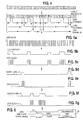
- FIG. 3 shows an exemplary allocation of a frame, with only ten slots out of the twenty-four slots being shown.
- the first slot, slot 1 carries control, or protocol information. This slot therefore carries the protocol channel.
- slot and channel. While a channel may comprise a single slot, a single channel can also comprise multiple slots.
- a voice circuit, V A is established over channel 2 in slot 2, and a separate voice circuit, VB, is established over channel 3 in slot 3.
- Data from a data source, such as computer 17, is transmitted over channel 4 in slot 4. This data stream is referenced as DA.
- the bandwidth (the amount of bits in a frame) allocated between voice and data is dynamic.
- An example illustrates this dynamic allocation of bandwidth. Assume the system has a pre-determined policy in which voice circuits have priority over data transmissions for bandwidth. In other words, when a voice circuit needs to be established, a data source must relinquish its slot (and bandwidth).
- FIG. 3a a frame is shown in which two additional voice circuits carrying voice information VG and VH are established. The voice circuits VG, V H are established over channels 4, 5 and replace the data transmissions DA, DB which were previously transmitted over channels 4, 5.
- the same exemplary policy can also dictate that when a slot becomes vacant and is not needed for a voice circuit, one of the data channels will occupy the slot so that the data channel will have a higher bandwidth. Alternatively, another data source could fill the slot no longer occupied by the voice circuit.
- This policy dynamically allocates the bandwidth of the link so that each slot is constantly used.
- Other policies reflecting various demands of a particular system, can also be used. The invention allows different policies to be used since it is flexible in its dynamic allocation of bandwidth.
- FIG. 4 An example of a typical frame is shown in FIG. 4.
- D1, D2, D3 generated by three different sources of data.
- the first slot of every frame is used for protocol bits P.
- this protocol information can be expanded to more than one slot, made less than one complete slot, or completely removed from the frame.
- the first data stream, D1 is transmitted on slots 2, 8, 15, 19 and 20.
- the second data stream, D2, is transmitted on slots 6 and 22.
- the third data stream, D3, is transmitted on slots 9, 12 and 13.
- a data stream may be spread out over several non-contiguous slots, such as data stream D1, some technique is required to transparently create a continuous packet stream. This is performed in the present invention using a "stutter clock".
- each destination of data has a synchronous line interface 40 that expects to receive data synchronously with a clock signal.
- the stutter clock technique described below provides the synchronous line interface 40 with a data clock signal that is synchronous with the data meant for that particular synchronous line interface 40.
- the clock input of synchronous line interface 40 is coupled to the output of an AND gate 42.
- the AND gate 42 receives at its inputs a line clock signal and a clock enable signal.
- the data signal and the output of AND gate 42 are sent to the synchronous line interface 40 by the receiving integrated link controller 14.
- FIG. 5a shows the line clock signal that is sent from the receiving integrated link controller 14 to all of the synchronous line interfaces 40.
- the clock enable 1 signal is sent by the receiving integrated link controller 14 only to the appropriate synchronous line interface 40 according to an allocation mask stored in the receiving integrated link controller 14. This mask, and its determination from the protocol signals sent over the protocol channel will be described in more detail later.
- the receiving integrated link controller 14 will therefore send out the clock enable 1 signal which will have logical highs that correspond to the slots on which data for data stream 1 is sent.
- the clock enable 1 signal will be high during slots 2, 8, 15, 19 and 20 (FIG. 5b).
- the data clock 1 signal (FIG. 5c) will be received at the synchronous line interface 40 synchronously with the data meant for the destination.
- the synchronous line interface 40 for a particular destination will only receive data meant for that particular destination at the same time as it receives the data clock signal.
- the destination is unaware of any gaps in the data stream since its synchronous line interface 40 is not clocked during the portions of the frame allocated to voice circuits and other data streams.
- FIGS. 5d-5g show the clock enables and data clocks for the two other data streams D2, D3 that are sent to different destinations.
- the following describes the transmission and reception of information over the integrated link using the integrated link controllers operating as a transmitter and a receiver.
- the information can include different types of information, such as data, voice, and protocol information. Specific methods for encoding the protocol information will be described separately later.
- FIG. 7A An embodiment of the transmitting path in an integrated link controller 12 is shown in FIG. 7A.
- the transmitting integrated link controller 12 has an integrated link T-carrier interface 50 with an output 51 coupled to the integrated link 16.
- the output 51 of the interface 50 carries the voice information from the voice channels, and the data from the data channels, in an integrated fashion.
- the information sent to the interface 50 is provided on line 52 from each of the synchronous line interfaces 40 coupled to the various sources and a transmit protocol message buffer 72a.
- the voice channels are carried over a line 54 through a gate 56 to the interface 50.
- the gate 56 is enabled during the transmission of the appropriate slot as described in the following paragraphs.
- the voice channels are provided from the PBX 24A to the T-carrier interface 58.
- the T-carrier interface 58 sends the voice channels over line 54 to the transmit gate 56.
- the T-carrier interface 58 is coupled to the voice channels of PBX 24A in a conventional manner.
- circuit monitor 70 detects this occurrence.
- Circuit monitor 70 sends request control information over line 75 to an integrated link processing unit 60.
- the integrated link processing unit 60 uses the request control information from circuit monitor 70 to generate an allocation mask protocol message and places it in a transmit protocol message buffer 72a.
- the integrated link processing unit 60 indicates over line 76 that slot usage has been granted to circuit monitor 70. This causes the T-carrier interface 58 to place the voice circuit in the allocated slot.
- Integrated link processing unit 60 loads a mask register 62 with the information describing the allocation of the multiplexed frame.
- the circuit monitor 70 detects in a conventional manner the termination of a voice connection and initiates the removal of the voice slot from the integrated frame by sending information to the integrated line processing unit 60.
- the integrated link processing unit 60 will place a message indicating the new allocation of slots in the transmit protocol message buffer 72a and then appropriately update the allocation mask register 62 according to the link protocol. In this manner, bandwidth can be added to or taken from the synchronous data channels.
- a data packet monitor 71 is also provided in the illustrated embodiment.
- the data packet monitor 71 is enabled by AND gate 42 to extract information from line 52 when synchronous line interface 40 places information from source D1 on the line 52.
- data source D1 is selected to control data bandwidth allocation for all the data sources D1-D3.
- Monitor 71 notifies the integrated link processing control 60 when there is to be a reallocation of bandwidth among the data channel sources D1-D3.
- the integrated link processing control 60 generates and loads an allocation protocol message into the transmit protocol message buffer 72a.
- the integrated link processing unit 60 will then load mask register 62 with the information describing the allocation of the multiplexed frame.
- the slots of the frame are assigned according to whether voice traffic is present. When there are no voice calls active, all the slots are assigned to the protocol channel and data sources in the following manner (where "p" is the protocol channel).
- D1 is using slots 2, 3 and 6.
- D2 is using slot 4 and 5.
- D3 is not allocated to any slot.
- only six slots are shown, the invention being applicable for any number of slots.
- the mask register 62 controls the presentation of voice channels, data channels and the protocol channel to the integrated link T-carrier interface 50 in the following manner.
- multiplexer 100 enables the contents of the corresponding mask register location onto allocation bus line 101.
- the contents on line 101 are fed into comparators 81, each of which drives a separate output enable line.
- one of the comparators 81 drives gate 56 to couple voice channels on line 54 to line 52 coupled to integrated link T-carrier interface 50.
- the comparators 81 feed inputs to different AND gates 42.
- Each of the AND gates 42 receives at its other input a transmit clock signal over line 53 from the integrated link T-carrier interface 50.
- the outputs of AND gates 42 correspond to a transmit "stutter" clock that is enabled for the portion of the frame during which the synchronous line interfaces 40 are to provide data over line 52 to integrated line T-carrier interface 50.
- the number of AND gates required is equal to the number of potential data channels that can be allocated bandwidth in mask register 62.
- One AND gate 42 is coupled to the transmit protocol message buffer 72a to enable the allocation information to be transferred to the receiving integrated link controller 14.
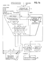
- FIG. 7b An embodiment of a receiving integrated link controller 14 is shown in FIG. 7b.
- the receiving integrated link controller 14 has an integrated link T-carrier interface 50 coupled to the integrated link 16.
- the input of the integrated link T-carrier interface 50 carries the voice information from the voice channels, the data from the data channels and allocation protocol messages as sent by a transmitting integrated link controller 12.
- the information received from the integrated link T-carrier interface 50 is carried on line 52 to each of the synchronous line interfaces 40 coupled to the various destinations, and also is carried to a receive protocol message buffer 72b.
- the voice channels are carried over the same line 52 to the integrated link T-carrier interface 58.
- the voice channels are provided from the T-carrier interface 58 to a PBX 24B in a conventional manner.
- the PBX 24B extracts the voice channels from the activated voice slots.
- the mask register 62 is loaded by the integrated link processing unit 60 as described in the following paragraphs.
- the contents of the mask register 62 control how the received frame is to be decomposed into voice information, synchronous data information, and protocol information.
- the multiplexer 100 enables the contents of the corresponding mask register location onto allocation bus line 101.
- the contents on allocation bus line 101 feed into comparators 81, only one of which will drive an output enable line.
- the comparators 81 will feed inputs to different AND gates 42.
- Each of the AND gates 42 receives at its other input the line clock signal on line 53 from the integrated link T-carrier interface 50 at its other input.
- the output of AND gates 42 correspond to a receive "stutter" clock that is enabled for the portion of the frame during which the synchronous line interfaces 40 are to receive data from line 52.
- One AND gate 42 is coupled to the receive protocol message buffer 72b to enable the reception of allocation information from the transmitting integrated link controller 12.
- the integrated link processing unit 60 takes the information from the buffer 72b to update the receive mask register 62.
- the receive mask register 62 is updated at the appropriate frame boundary as indicated by the protocol message so that the receive mask register 62 is in agreement with the allocation of slots arriving at the integrated link T-carrier interface 50.
- FIGS. 7a and 7b will be used to illustrate an embodiment of an "explicit" AM encoding technique.
- the following is the assignment of binary values for the protocol channel, data channels and voice circuits illustrated in FIGS. 7a and 7b:
- FIG. 12 illustrates two PBXs being controlled by each integrated link controller. This feature can be utilized on higher bandwidth carrier facilities like T3, which offer 44.736 mBits/second per link, since a single PBX may not be able to handle the entire bandwidth of such a high speed channel.
- a method according to the present invention encodes allocation mask information with only two bits per slot plus a synchronization bit per protocol message. This technique relies on constraining two characteristics of the AM exchange between the transmitting and receiving integrated link controllers.
- the first constraint is on the ability of the explicit method to select and de-select data channels into and out of service with the integrated link protocol, without affecting the ability of the protocol to re-assign bandwidth among data channels in service.
- the explicit method for example, D3, which is presently out of service, can normally be brought into service with the same ease as the reassignment of bandwidth to other data channels already in service.
- the D set does not change frequently and therefore does not need to be sent in every protocol message.
- the D set exchange By causing the D set exchange to use a normal handshake verified packet exchange in a data channel outside of the integrated link protocol channel, protocol channel bandwidth is conserved.
- the protocol channel will only need to be concerned with the apportionment of bandwidth between data channels already in service and not with the activation and deactivation of particular data channels.
- a single synchronization bit is necessary to select one of two D sets as an in service, active set. Two D sets are necessary so that one can be in service while the other is being updated for use at a future time.
- the second characteristic to constrain is the ability of the explicit method to assign bandwidth to individual data channels in any arbitrary order in a frame. That is, instead of allowing the following allocation (e.g., in a frame with no voice circuits allocated):
- VDAM Voice Data Allocation Mask
- DCBM Data Channel Boundary Mask
- VDAM indicates whether a slot should provide voice circuit or data channel service.
- DCBM is a mask of data channels only, indicating how the members of the D set are to be apportioned bandwidth in a frame from non-voice allocated or free slots.
- DCBM in effect describes the allocation of bandwidth to data channels as a set of movable boundaries filled by values from the D set.
- a DCAM Data Channel Allocation Mask
- a DCAM Data Channel Allocation Mask
- D Set [Set of in service data channels used with boundaries specified in DCBM to create DCAM]
- the DCAM created by combining the D Set with the boundaries specified in DCBM is [P D1 D1 D1 D2 D2]
- the resultant AM is formed by ANDing the DCAM with the VDAM.
- the AM is [P D1 Vx D1 Vx D2]
- the resultant AM derived implicitly in this embodiment of the invention, contains the same information as the original explicit AM.
- the position dependent requirement of the voice circuit slots has been maintained, though the order of some of the data channel values has been changed (slot 4 contained D2 and slot 6 contained D1). This is consistent, however, with the ability of the invention to provide position independent bandwidth to data channels.
- the voice circuit slots are position dependent in that the PBX relies on each one maintaining a fixed position in the frame in order to locate them and distinguish them from each other.
- the data channels are not position dependent and can be allocated in any manner that would increase the efficiency of an AM exchange.
- Implicit encoding uses 2 bits per slot plus a D set synchronization bit, so the total number of bits, t, required to support bandwidth allocation is:
- the explicit method required 38% more bits (18) than the implicit method (13). This represents a 27% savings of the implicit over the explicit method.
- FIG. 11 illustrates how the implicit mechanism would be implemented to replicate the less efficient explicit AM allocation function in the embodiments of FIGS. 7a and 7b.
- the VDAM Voice Data Allocation Mask
- the VDAM register 63 indicates whether a slot is to provide voice circuit or data channel service.
- the output of a multiplexer 107 is used to enable one of the three input AND gates 43 for data channel operation, depending on the outputs of comparators 81, or enable a voice circuit to utilize the integrated link by turning on gate 56 of FIG. 7 a , through inverter 44.
- the AND gates 43 provide the same stutter clocking described as part of the embodiment of FIGS. 7 a and 7b.
- the DCBM Data Channel Boundary Mask
- the DCBM register 64 indicates whether a D set pointer 102 should be incremented or remain at its present value at each slot time. If incremented, a new data channel value will be read from a D set memory 106 onto line 105, forming the DCAM (Data Channel Allocation Mask) entry for that slot, analogous to the value present on line 101 of the explicit encoding technique illustrated in FIGS. 7 a and 7 b . If it is not incremented, the present data channel value pointed to in the D set memory 106 will be used for that slot time.
- DCAM Data Channel Allocation Mask
- the D set memory 106 holds both an active D set and a D set being updated for use at a future time.
- a synchronization bit in the protocol message that is stored in a synchronization bit register 104 indicates which D set is the active one. In this example, D set 1 is active since register 104 contains a 1.
- the D set pointer 102 and synchronization bit 104 form a 3 bit address that is input into the D set memory 106.
- the active D set in memory 106 and the DCBM in register 64 are used to create DCAM, as described previously.
- the DCAM does not reside in a register, but each value of the DCAM for each slot is made available on line 105 for subsequent use by comparators 81 in order to determine which AND gate 43 should be turned on, if any.
- any request for a slot by the DCAM can only be granted if there is a free slot, that is if the value from the VDAM multiplexer 107 is a 1 for that particular slot, indicating that no voice circuit is being requested by the PBX 24a.
- the first constraint is on the ability of the implicit method to re-assign bandwidth at high speeds utilizing protocol messages among data channels in service. This would be accomplished by exchanging both the DCDM mask an the D set through normal handshake verified packet exchange in a data channel outside of the integrated link protocol channel, and only send VDAM and the synchronization bit in the protocol. The synchronization bit would be needed in order to pick an active DCBM, along with a corresponding D set.
- VDAM bit per slot
- Dynamic allocation between the voice circuits and data channels would be supported as before, however, the set of in service data channels and allocation of in service data channels could be changed only by utilizing the slower exchange mechanism outside of the integrated link protocol channel.
- One possible use for this scheme would be to specify a primary set of data channels and a back-up set used to provide fault tolerance in a system.
- the second constraint eliminates the ability of the implicit method to re-assign bandwidth among data channels in service and to specify new sets of data channels in service. This would be accomplished by utilizing a fixed DCBM mask and D set, and sending only VDAM in the protocol.
- the protocol used in the present invention provides for dynamic allocation of the bandwidth among the different types of information traffic carried on the integrated link 16. As described above, the allocation of the slots among the various channels is determined by the allocation mask. In order for transmission to operate properly, both the transmitting and receiving integrated link controllers 12, 14 must have identical copies of the allocation masks in a synchronous manner. To achieve the full benefit of integration of voice and data information on a single link, the masks must be changed dynamically in response to the fluctuating demands for the voice circuits, according to a pre-determined policy. The protocol maintains synchronization of the allocation masks at the transmitter and the receiver without disrupting the ongoing use of the channel, even as these masks are dynamically changed.
- the transmitting integrated link controller 12 uses the allocation mask to multiplex voice and data information into their allocated slots in a frame, while the receiving integrated link controller 14 uses its mask to pick apart the received frames.
- the system will only operate correctly if the mask at the transmitting integrated link controller 12 and the receiving integrated link controller 14 are synchronized. In other words, the mask at the receiving integrated link controller 14 that is used to pick apart a given frame must be identical to the mask used at the transmitting integrated link controller 12 to multiplex voice and data information into that frame.
- the synchronization is achieved by the allocation protocol whose function is to change the masks at the transmitting and receiving integrated link controllers 12, 14 synchronously, and to ensure that they remain synchronized when the allocation is not changing.
- the protocol information is designed to change the allocation of the link reliably in the face of errors.
- the probability of switching over to an incorrect allocation is much lower than the probability of errors on the channel.
- R is the reliability of this mechanism (i.e., detecting an error in the protocol channel).
- the protocol channel provides a mechanism by which the percentage of control traffic can be adjusted without affecting the reliability of the protocol transfer mechanism.
- the control overhead (c) can be expressed as a fraction of the channel bandwidth B.
- the control overhead comprises an entire slot, equal to 8 bits.
- the bandwidth of the protocol channel can be such that it takes up any number of bits in any number of frames. This is also true for any of the data channels and voice circuit channels. For example, 48 four bit slots could be defined on a TI link versus the more standard 24 eight bit slots.
- the invention provides a mechanism that allows the change of channel allocation as fast as possible subject to the constraints of reliability R and channel overhead c.
- D is the delay between the inception of a request for a change in allocation and the time the transmitting integrated link controller 12 switches over to the new allocation mask.
- the receiving integrated link controller 14 will switch over to the new allocation mask one link propagation delay after the transmitting integrated link controller does.
- the amount of bandwidth assigned to the protocol channel determines how quickly allocation information can be transmitted to the receiving integrated link controller 14 and how quickly the allocation mask can be updated.
- the characteristics of the protocol channel are controlled by the setting of the parameters R, C, D, B and S (the number of slots within the frame).
- the present invention allows for fixing some of these parameters and leaving others to be adjusted by the users of the integrated link channel.
- the present invention guarantees that if the transmitting integrated link controller 12 switches over to a new allocation at time T, the receiving integrated link controller 14 also switches over to the new allocation at time T + link propagation delay with reliability R.
- the protocol does not acknowledge the transmitter to the protocol information frames, but responds drastically to errors in the protocol channel.
- the present invention uses redundancy techniques on the transmitter side (12) and error detection, selection, and recovery at the receiver side (14).
- the protocol channel normally contains the information that will allow the specification of an allocation mask.
- a transmitting integrated link controller 12 decides to change the allocation of slots within a frame it sends the information to generate a new allocation mask up to N times in the control channel.
- the protocol information is sent each time with a CRC that detects an error in the allocation information with high probability.
- Each of these N messages sent also contains the time q at which the receiving integrated link controller should switch over the new allocation mask.
- the receiving integrated link controller 14 Because the messages sent by the transmitting integrated link controller 12 are idempotent, if the receiving integrated link controller 14 gets-one or more of the N messages sent with a correct CRC it switches over to the new allocation.
- the invention prescribes that if the receiving integrated link controller 14 receives N CRC errors in a row, the receiver cannot be sure of the allocation desired by the transmitting integrated link controller 12.
- the integrated link processor unit 60 detects this occurrence, and provides notification in a conventional manner that the integrated link channel is broken.
- the receiving integrated link controller 14 cannot process received frames correctly until an allocation packet with correct CRC is received and the frame pointed to by this allocation packet arrives. In the event that the number of CRC errors in a period of Y frames exceeds some threshold value I, the present invention will reset the channel and notify the customers of the integrated link channel in a conventional manner.
- the transmitting integrated link controller can periodically resend the current allocation information with a time of F+1 frames in the future.
- This redundant transmission of the allocation information provides a self-stabilizing property in that no matter how bad the channel was in the past, the statistical multiplexing system will stabilize in finite time after the channel stops malfunctioning due to excessive bit error rates.
- the described embodiment of the preferred invention sends the allocation information in the protocol packet in successive frames, one byte at time. Thus, it takes six frames before the entire protocol packet is sent by a transmitting integrated link controller 12.
- more or less than one slot can be assigned to the protocol channel, (i.e., overhead c) to provide faster or slower transfer of allocation information and switching of the allocation mask.
- FIG. 8 illustrates the six consecutive frames sent by a transmitting integrated link controller 12.
- the first slot in each frame contains one byte of a protocol packet of information.
- the first three frames contain encoded information describing the allocation mask.
- the fourth frame contains the number of frames q from the first frame of this sequence of frames (that make up a packet) at which time the mask is to be changed.
- the frames 5 and 6 contain the CRC for the protocol packet.
- the protocol packet is sent vertically over several frames, rather than horizontally in a single frame. Note that the remaining 23 slots in each frame can continue to be used for voice or data channels.
- the transmitting integrated link controller 12 decides at frame J to change the allocation masks. Beginning at frame (J + 1), which is the first frame of the first protocol packet, the transmitting integrated link controller 12 sends an allocation information packet essentially saying "change to the new mask 18 frames after the first frame of this protocol packet. " Beginning at frame (J + 7), the transmitting integrated link controller 12 will send a second protocol packet saying "change to the new mask 12 frames after the first frame of this protocol packet". Beginning at frame (J + 13), it sends a third packet saying "change to the new mask 6 frames after the first frame of this protocol packet.” The transmitting integrated link controller 12 and the receiving integrated link controller 14 switch to the new mask beginning with frame (J + 19).
- the receiving integrated link controller 14 will therefore invoke an error handling procedure.
- a typical error handling procedure forces a re-initialization of the link, which is a drastic response, but is appropriate behavior for a link exhibiting unusually high noise characteristics.
- the example used provides a very reliable allocation mechanism.
- the CRC error rate can be used to monitor the quality of the integrated link as an added network management benefit.
- the changing of the allocation mask is transparent such that the remaining bandwidth of the integrated link 16 can continue to carry useful information between the transmitting integrated link controller 12 and the receiving integrated link controller 14.
- a protocol packet can be sent three times in eighteen frames, it will take only 2.25 milliseconds to change the allocation mask. This is adequate for many real-time allocations.
- protocol packets allow the bandwidth (or control overhead), the speed of switching masks, and robustness (ensuring of accuracy) to be traded off against each other to suit a wide range of performance requirements.
- the protocol can be used to match a range of configurations including either PCM or ADPCM speech encoding schemes, and any frame format and any transmission rate such as American DS1, or European CEPT.
- a future feature of the present invention allows the protocol channel to configure the link in voice only or data only modes so that control overhead is eliminated altogether. This would be used only for systems in which dynamic allocation of bandwidth is not used. Link initialization would then be used to restart dynamic link operation.
- the speed of mask re-allocation allows the integrated link to utilize silence detection in order to reclaim unused voice circuit bandwidth for use in the data channels. For example, when one person is finished speaking on a voice channel, a measurable pause can be detected.
- the switching of allocation masks can be performed with the present invention fast enough to make it worthwhile to use the bandwidth of that voice channel to transmit data until that voice channel is needed again.
- the bandwidth allocated to the data channel will be reallocated to the voice channel, at a speed fast enough so as to be invisible to the coversants.
Abstract
An integrated communications link (16) in a communications network is provided with apparatus which allows dynamic allocatability of bandwidth among a plurality of channels. At least three different types of information can be carried on these channels, and the bandwidth of each channel is dynamically adjustable so that it can be changed according to a determinable scheme. The link also sends error control information with a message that informs the receiver how the bandwidth is to be allocated, this error control information providing an extremely high level of assurance that the receiver of the information will know how the received information is to be allocated.
Description
- The present invention relates to multiplexing in a communications link. More particularly, the invention relates to an integrated multiplexed link having dynamically allocatable bandwidth among a plurality of channels, and a protocol for the transmission of allocation information over the integrated link.
- In today's world, there is a growing requirement for transferring different types of information over various distances via communications links. This information can be, for example, data generated by a computer, imaging data from a video camera, or any other of a number of different forms of data. This data often has to share the communications link with voice circuits that carry human conversations.
- In modern communication systems, the carrying of multiple conversations over a common link is most frequently accomplished by the well-known methods of time division multiplexing (TDM) or frequency division multiplexing (FDM). One common multiplexing system is the American T1 system which has a link of 1.544 Mbit/sec that is divided into 24 slots of 64 Kbit/sec. This division is implemented by continuously sending "frames" of 192 bits. Each frame is divided into 24 slots, so that each slot has 8 bits. Since each slot can carry a different conversation, 24 different conversations can be carried simultaneously over the T1 system link, with 8 bits of each conversation transmitted every frame.
- The different types of information (voice, data, image, etc.) that can be carried over a link having different transmission characteristics and requirements. For example, voice information (a conversation) is characterized by low to medium bandwidth and low latency. Latency is the period of time between the occurrence of an event and the time at which the event is recognized, while bandwidth is defined here as the bits transmitted per second. (Since a defined number of frames are transmitted per second, the number of bits allocated within a single frame will also be referred to as bandwidth). By contrast, computer data can have low to high bandwidth and relatively high latency. Image data can have extremely high bandwidth and low to high latencies.
- As stated above, the different types of information must often be carried over the same link. There is, for example, at least one proposed system that provides an integrated network that carries both data and voice information over the same link. (For ease of description, all other types of information besides voice, such as computer data, image information, etc., will be henceforth referred to as "data".) This network is the Integrated Services Digital Network (ISDN), proposed as an industry standard.
- The ISDN network allows both voice and data to be carried over the same link, with voice occupying some slots, and data occupying other slots, with at least one slot acting as a control slot. The information carried in the control slot tells the receiver how the slots in each frame are allocated, i.e., which slots are assigned to which receivers at any particular time. An example follows, with reference to FIG. 1.
- The 24 slots of a frame carried by the ISDN system is shown in FIG. 1. The first slot is a slot for control, and is thus the control channel. The remaining 23 slots can be assigned to 23 different, simultaneous transfers of information. Each separate transfer of information is labeled a channel, so that the ISDN system can support up to 23 separate channels, and one control channel. However, each channel can occupy one or more contiguous slots.
- The ISDN system suffers from a number of drawbacks. One of these drawbacks is its inflexibility in its allocation of slots. For example, assume that one type of information transfer needs higher bandwidth than can be provided by one slot. In the ISDN system, this is accomplished by grouping together a number of contiguous slots, to form a channel having higher bandwidth since each frame is now allocated to carry more information for that particular information transfer.
- The requirement that the slots be contiguous for information carried over the same channel leads to inefficient use of the link in the ISDN systems. This is because certain allocations can cause, for example, only single slots to be available when a channel needs two or more contiguous slots. In such a circumstance, either the channel waits for two contiguous slots to become free, or a re-allocation must be performed. In either case, the link is being inefficiently used.
- Another drawback to the ISDN system is the relatively long time it takes to change the allocation scheme of the slots. When the allocation scheme is to be changed, the sender sends the receiver the new allocation scheme. Upon receipt of the new allocation scheme, the receiver will then send back an acknowledgment signal. The sender starts sending information according to the new allocation scheme only when it receives the acknowledgment signal from the receiver. During this whole time period, no useful information can be sent because both sender and receiver cannot be sure that the receiver has the correct new allocation scheme until after the sender receives the acknowledgment signal. When the link spans the entire country so that the propagation of the signals takes a relatively long time (30 m sec, for example), the acknowledgment method of changing the allocation scheme is undesirably slow.
- A need therefore exists for an integrated network that can carry both voice and data over the same link, this network providing flexibility in its allocation of slots. The network should also be able to switch the allocation scheme very quickly and transparently, so that information can be transferred during the switching process.
- According to one aspect of the present invention there is provided a system for carrying multiple types of information in a multiplexed manner in a framed format, on an integrated link, each frame of the framed format being divided into portions, the system comprising:
at least two integrated link controllers, each integrated link controller being operable as a transmitter and a receiver to transmit and receive a plurality of information signals in each frame, each information signal occupying an allocated amount of bandwidth in at least one portion of each frame;
means for dynamically changing the allocation of the bandwidth of each information signal;
means for generating error control information that is transmitted from an integrated link controller operating as a transmitter to an integrated link controller operating as a receiver;
means for checking error control information in the integrated link controller operating as a receiver; and
means for allocating the bandwidth of each individual information signal among a plurality of contiguous or non-contiguous portions of the frame. - The present invention provides a system having an integrated link that carries multiple types of information in a multiplexed manner. The system has a multiplexed integrated link that carries multiple information signals in a framed format. Each information signal occupies an allocated amount of bandwidth in a portion of each frame in the framed format. Two integrated link controllers are coupled to the ends of the multiplexed integrated link. Each integrated link controller is operable as a transmitter and as a receiver. The system has means for dynamically changing the allocation of the bandwidth of the information signals, where the bandwidth of each individual information signal is allocatable among contiguous or noncontiguous portions of the frame.
- According to a second aspect of the invention there is provided a system for carrying multiple types of information in a multiplexed manner on a multiplexed integrated link in a framed format, each frame of the framed format being divided into portions, the system comprising :
at least two integrated link controllers that are couplable to an integrated link, each integrated link controller being operable as a transmitter and a receiver to transmit and receive a plurality of information signals in each frame, each information signal occupying an allocated amount of bandwidth in at least one portion of each frame;
means for dynamically changing the allocation of the bandwidth of each information signal;
means for generating error control information that is transmitted from an integrated link controller operating as a transmitter to an integrated link controller operating as a receiver;
means for checking error control information in the integrated link controller operating as a receiver;
means for allocating the bandwidth of each individual information signal among a plurality of contiguous or non-contiguous portions of the frame; and
a set of information signal sources coupled to one of the integrated link controllers, and a set of information signal destinations coupled to the other of the integrated link controllers. - The present invention also extends to a third aspect according to which there is provided a method of switching the allocation of bandwidth of information signals in integrated link controller arranged to transmit and receive information being coupled by a time division multiplexed link that carries multiple information signals in a framed format, each frame in the framed format being divided into slots of a specified bandwidth, an allocation mask stored in a mask register indicating the number of slots each information signal is allocated, the method comprising:
sending protocol information from the transmitting integrated link controller in protocol packets, each protocol packet containing the allocation mask, and error control information, and each protocol packet being transmitted vertically over a plurality of frames;
receiving the protocol packets in the receiving integrated link controller; and
using the received allocation mask to dynamically switch the allocation of the bandwidth. - The dynamic allocation of the bandwidth of the information signals according to the present invention provides an integrated link of great flexibility. This is because the allocation of the bandwidth of each individual information signal on the multiplexed integrated link can be dynamically changed to accommodate the bandwidth and the latency requirements of different types of information signals. For example, if one of the information signals is image data, the image data can be allocated a relatively large bandwidth. Other types of information signals, such as data from a computer, can be provided the appropriate bandwidth as needed.
- The dynamic changing of the allocation of the bandwidth also allows the multiplexed integrated link to carry voice signals. One type of allocation policy provides that voice signals have precedence over other types of information signals. However, to provide full utilization of the integrated link, when a voice signal is no longer being used, the allocation of the bandwidth can be quickly and dynamically changed to allow other data to be transmitted over the bandwidth vacated by the voice circuit.
- The present invention also provides greater flexibility in its allocation of bandwidth since an individual information signal is allocatable among contiguous or noncontiguous portions (or slots) of the frame. Therefore, an individual information signal does not have to wait for two contiguous slots to be free before it is allocated those slots.
- The present invention also provides a fast protocol for dynamically changing the allocation of the bandwidth of the information signals. Protocol information is transferred from a transmitting integrated link controller to a receiving integrated link controller. Part of the protocol information is an allocation mask which indicates how the slots of each frame are allocated to the various information signals. The transmitting integrated link controller uses the allocation mask to multiplex voice and data information into their allocated slots in the frame, while the receiving integrated link controller uses the allocation mask to pick apart the received frames. Therefore, both the transmitting and receiving link controllers need to use the same mask for a given frame.
- Protocol information can be sent vertically, i.e. spread out over successively transmitted frames. Furthermore, since the bandwidth in a particular frame can be dynamically changed, the bandwidth of the protocol channel, and thus the speed of switching allocation masks, can be easily changed to suit a particular application. The present invention therefore allows an adjustable trade-off of protocol bandwidth (or control overhead) with the speed of switching masks.
- Robustness (the ensuring of accuracy) is also adjustable and can be traded off with bandwidth and speed in the present invention. Protocol information is repetitively sent a certain number of times, this number being adjustable. The more times the information is repeated, the more robust the transfer of protocol information will be. This will be at the expense of mask switching speed and/or bandwidth.
- Another advantage of the protocol of the present invention is that no acknowledgment signal by the receiving integrated link controller is necessary, thereby making bandwidth allocation faster and more efficient, as described in the next paragraph. This is because the protocol information is repeated in protocol packets, and if merely one of these protocol packets is determined to be a correct protocol packet, the transmitting and receiving integrated link controllers will both have the same allocation masks with a high degree of confidence.
- The protocol of the present invention also has the advantage that useful information can be transferred while the protocol information is being transmitted. This is due to the fact that the protocol information is sent over only a portion of a frame, leaving the rest of the frame for continuing information transfers.
- These and other preferable features of the present invention are defined in the accompanying claims.
- The present invention can be put into practice in various ways some embodiments of which will now be described by way of example with reference to the accompanying drawings in which:
- FIG.1 illustrates a conventional 24 slot frame;
- FIG.2 illustrates a system constructed in accordance with an embodiment of the present invention;
- FIG. 3 illustrates the first ten slots of an exemplary frame;
- FIG. 3a illustrates the exemplary frame of FIG. 3 that has had its slots reallocated according to the embodiment of the present invention;
- FIG. 4 illustrates another example of a frame;
- FIG. 5a illustrates a line clock generated by the present invention;
- FIGS. 5b, 5d and 5f illustrate clock enable signals for the respective data channels illustrated in FIG. 4;
- FIGS. 5c, 5e and 5g illustrate the data clock signals generated by the present invention for the respective data channels illustrated in FIG. 4;
- FIG. 6 shows an exemplary embodiment of an arrangement to provide the data clock signal to a synchronous line interface;
- FIGS. 7a and 7b show exemplary embodiments of transmitting and receiving integrated link controllers;
- FIG. 8 shows six successive frames, with only the protocol channel for each frame being shown;
- FIGS. 9a and 9b show examples of an allocation mask before and after voice circuits replace data channels in the allocation mask;
- FIG. 10 shows graphically the process of implicit allocation mask encoding;
- FIG. 11 illustrates a portion of the integrated link controllers of FIGS. 7a and 7b that are modified to permit implicity allocation mask encoding;
- FIG. 12 illustrates another embodiment of the invention, similar to FIG. 2, but having multiple PBXs ; and
- FIG. 13 illustrates a point-to-multipoint coupling of integrated link controllers constructed in accordance with an embodiment of the present invention.
- To understand the type of communication services provided by the present invention, a network comprising integrated links will first be described. This will be the basis for a following description of an embodiment according to the present invention of a transmitting and receiving integrated link controller. The derivation of explicit allocation mask encoding illustrated in the embodiment will then be described along with an enhanced implicit encoding technique used to provide more efficient protocol channel utilization. The parameters and operation of this protocol channel will then be described for the invention.
- An example of a
system 10 constructed in accordance with an embodiment of the present invention is shown in FIG 2. Thesystem 10 has a time division multiplexed link, such as the North American T1 link, comprising integrated link controls 12, 14 and alink 16 coupling the two integrated link controls 12, 14. The standard T1 link provides the necessary framing information to allow integrated link processing according to the present invention. - A synchronous time division multiplexed frame structure provides a frame of fixed duration that is subdivided into an integral number of time slots. The North American T1 frame structure defines a frame duration of 125 microseconds that is subdivided into 24 time slots made up of eight bits each. Each time slot has a duration of 5.18 microseconds. An additional framing bit provides for a total line bandwidth of 1.544 Mbits/second where each time slot has an effective transfer rate of 64 Kbits/second.
- It should be recognized that any type of multiplexed link could be used, for example, the European link which provides frames divided into 30 time slots. Further, it is contemplated to use frequency division multiplexed links instead of time division multiplexed links.
- The
integrated link controller 12 is coupled to twocomputers integrated link controller 12 is also separately coupled to a private branch exchange (PBX) 24A.Separate telephone units 26A-26D are coupled to thePBX 24A. - At the other end of the
link 16, theintegrated link controller 14 is similarly coupled tocomputers PBX 24B. ThePBX 24B, in turn, is coupled to telephone sets 26E-26H. - The arrangement of FIG. 2 is merely exemplary, such that the
integrated link controllers - For the following discussion, integrated
link controller 12 will be considered the sender or transmitter, while theintegrated link controller 14 will be the receiver. Thecomputers PBX 24A will be termed the sources, while thecomputers PBX 24B will be termed the destinations. Although the terms transmitters and receivers are used for the following description, it should be apparent that the transmittingintegrated link controller 12 has a companion receiver and the receivingintegrated link controller 14 has a companion transmitter, so that simultaneous two-way communication is provided. - The
system 10 of FIG. 2 transfers information in frames, as discussed earlier. FIG. 3 shows an exemplary allocation of a frame, with only ten slots out of the twenty-four slots being shown. The first slot,slot 1, carries control, or protocol information. This slot therefore carries the protocol channel. Note that there is a distinction between the terms "slot" and "channel". While a channel may comprise a single slot, a single channel can also comprise multiple slots. - A voice circuit, VA, is established over
channel 2 inslot 2, and a separate voice circuit, VB, is established overchannel 3 inslot 3. Data from a data source, such ascomputer 17, is transmitted overchannel 4 inslot 4. This data stream is referenced as DA. A second data source, such ascomputer 18, transmits a data stream DB overchannel 5 inslot 5. - In similar fashion, four more voice circuits VC, VD, VE, VF are transmitted over the
channels slots channel 7. The remaining slots 11-24 (not shown) carry further voice circuits or data transmissions. - The bandwidth (the amount of bits in a frame) allocated between voice and data is dynamic. An example illustrates this dynamic allocation of bandwidth. Assume the system has a pre-determined policy in which voice circuits have priority over data transmissions for bandwidth. In other words, when a voice circuit needs to be established, a data source must relinquish its slot (and bandwidth). In FIG. 3a, a frame is shown in which two additional voice circuits carrying voice information VG and VH are established. The voice circuits VG, VH are established over
channels channels - The same exemplary policy can also dictate that when a slot becomes vacant and is not needed for a voice circuit, one of the data channels will occupy the slot so that the data channel will have a higher bandwidth. Alternatively, another data source could fill the slot no longer occupied by the voice circuit. This policy dynamically allocates the bandwidth of the link so that each slot is constantly used. Other policies, reflecting various demands of a particular system, can also be used. The invention allows different policies to be used since it is flexible in its dynamic allocation of bandwidth.
- An example of a typical frame is shown in FIG. 4. In this example, there are three different data streams, D1, D2, D3 generated by three different sources of data. As can be seen from the diagram, the first slot of every frame is used for protocol bits P. As will be explained later, this protocol information can be expanded to more than one slot, made less than one complete slot, or completely removed from the frame. The first data stream, D1, is transmitted on
slots slots slots - For compatibility reasons, it is important that the destinations of data packets (i.e.
computers 20, 22) receive the data packets in continuous packet streams rather than asynchronously. Since a data stream may be spread out over several non-contiguous slots, such as data stream D1, some technique is required to transparently create a continuous packet stream. This is performed in the present invention using a "stutter clock". - Referring to FIG. 6, each destination of data (as opposed to voice) has a
synchronous line interface 40 that expects to receive data synchronously with a clock signal. The stutter clock technique described below provides thesynchronous line interface 40 with a data clock signal that is synchronous with the data meant for that particularsynchronous line interface 40. As can be seen in FIG. 6, the clock input ofsynchronous line interface 40 is coupled to the output of an ANDgate 42. The ANDgate 42 receives at its inputs a line clock signal and a clock enable signal. The data signal and the output of ANDgate 42 are sent to thesynchronous line interface 40 by the receivingintegrated link controller 14. - Referring to FIGS. 5a-5g, FIG. 5a shows the line clock signal that is sent from the receiving
integrated link controller 14 to all of the synchronous line interfaces 40. The clock enable 1 signal is sent by the receivingintegrated link controller 14 only to the appropriatesynchronous line interface 40 according to an allocation mask stored in the receivingintegrated link controller 14. This mask, and its determination from the protocol signals sent over the protocol channel will be described in more detail later. - For receiving data channel D1, the receiving
integrated link controller 14 will therefore send out the clock enable 1 signal which will have logical highs that correspond to the slots on which data fordata stream 1 is sent. In this example, the clock enable 1 signal will be high duringslots data clock 1 signal (FIG. 5c) will be received at thesynchronous line interface 40 synchronously with the data meant for the destination. In other words, thesynchronous line interface 40 for a particular destination will only receive data meant for that particular destination at the same time as it receives the data clock signal. The destination is unaware of any gaps in the data stream since itssynchronous line interface 40 is not clocked during the portions of the frame allocated to voice circuits and other data streams. - This allows the use of standard synchronous line interfaces 40, so that they do not have to be adapted to be coupled to the
system 10. The remaining FIGS. 5d-5g show the clock enables and data clocks for the two other data streams D2, D3 that are sent to different destinations. - The following describes the transmission and reception of information over the integrated link using the integrated link controllers operating as a transmitter and a receiver. The information can include different types of information, such as data, voice, and protocol information. Specific methods for encoding the protocol information will be described separately later.
- An embodiment of the transmitting path in an
integrated link controller 12 is shown in FIG. 7A. The transmittingintegrated link controller 12 has an integrated link T-carrier interface 50 with anoutput 51 coupled to theintegrated link 16. Theoutput 51 of theinterface 50 carries the voice information from the voice channels, and the data from the data channels, in an integrated fashion. The information sent to theinterface 50 is provided online 52 from each of the synchronous line interfaces 40 coupled to the various sources and a transmitprotocol message buffer 72a. The voice channels are carried over aline 54 through agate 56 to theinterface 50. Thegate 56 is enabled during the transmission of the appropriate slot as described in the following paragraphs. The voice channels are provided from thePBX 24A to the T-carrier interface 58. The T-carrier interface 58 sends the voice channels overline 54 to the transmitgate 56. The T-carrier interface 58 is coupled to the voice channels ofPBX 24A in a conventional manner. - When the voice channels request the use of a slot at T-
carrier interface 58 by conventional means, circuit monitor 70 detects this occurrence. Circuit monitor 70 sends request control information overline 75 to an integratedlink processing unit 60. The integratedlink processing unit 60 uses the request control information from circuit monitor 70 to generate an allocation mask protocol message and places it in a transmitprotocol message buffer 72a. The integratedlink processing unit 60 indicates overline 76 that slot usage has been granted to circuit monitor 70. This causes the T-carrier interface 58 to place the voice circuit in the allocated slot. Integratedlink processing unit 60 loads amask register 62 with the information describing the allocation of the multiplexed frame. - The circuit monitor 70 detects in a conventional manner the termination of a voice connection and initiates the removal of the voice slot from the integrated frame by sending information to the integrated
line processing unit 60. The integratedlink processing unit 60 will place a message indicating the new allocation of slots in the transmitprotocol message buffer 72a and then appropriately update theallocation mask register 62 according to the link protocol. In this manner, bandwidth can be added to or taken from the synchronous data channels. - Similarly, a data packet monitor 71 is also provided in the illustrated embodiment. The data packet monitor 71 is enabled by AND
gate 42 to extract information fromline 52 whensynchronous line interface 40 places information from source D1 on theline 52. In this embodiment, data source D1 is selected to control data bandwidth allocation for all the data sources D1-D3.Monitor 71 notifies the integratedlink processing control 60 when there is to be a reallocation of bandwidth among the data channel sources D1-D3. The integratedlink processing control 60 generates and loads an allocation protocol message into the transmitprotocol message buffer 72a. The integratedlink processing unit 60 will then loadmask register 62 with the information describing the allocation of the multiplexed frame. In the illustrated example in FIGS. 7a and 7b, the slots of the frame are assigned according to whether voice traffic is present. When there are no voice calls active, all the slots are assigned to the protocol channel and data sources in the following manner (where "p" is the protocol channel). - In the illustrated example of a mask allocation seen in FIG. 9a, only two channels D1, D2 are active. D1 is using
slots slot - As voice calls are initiated and allocation of the frame to these voice calls take place, slots assigned to the transmission of information from the data sources are re-assigned to carry the voice information. An example would be when voice V1 and voice V2 are assigned to
slots - The
mask register 62 controls the presentation of voice channels, data channels and the protocol channel to the integrated link T-carrier interface 50 in the following manner. As the integrated link T-carrier interface 50 sequences through the slots of the transmitted frame,multiplexer 100 enables the contents of the corresponding mask register location ontoallocation bus line 101. The contents online 101 are fed intocomparators 81, each of which drives a separate output enable line. In the case of voice slots, one of thecomparators 81drives gate 56 to couple voice channels online 54 toline 52 coupled to integrated link T-carrier interface 50. For data channels, thecomparators 81 feed inputs to different ANDgates 42. - Each of the AND
gates 42 receives at its other input a transmit clock signal overline 53 from the integrated link T-carrier interface 50. The outputs of ANDgates 42 correspond to a transmit "stutter" clock that is enabled for the portion of the frame during which the synchronous line interfaces 40 are to provide data overline 52 to integrated line T-carrier interface 50. The number of AND gates required is equal to the number of potential data channels that can be allocated bandwidth inmask register 62. One ANDgate 42 is coupled to the transmitprotocol message buffer 72a to enable the allocation information to be transferred to the receivingintegrated link controller 14. - An embodiment of a receiving
integrated link controller 14 is shown in FIG. 7b. The receivingintegrated link controller 14 has an integrated link T-carrier interface 50 coupled to theintegrated link 16. The input of the integrated link T-carrier interface 50 carries the voice information from the voice channels, the data from the data channels and allocation protocol messages as sent by a transmittingintegrated link controller 12. The information received from the integrated link T-carrier interface 50 is carried online 52 to each of the synchronous line interfaces 40 coupled to the various destinations, and also is carried to a receiveprotocol message buffer 72b. The voice channels are carried over thesame line 52 to the integrated link T-carrier interface 58. The voice channels are provided from the T-carrier interface 58 to aPBX 24B in a conventional manner. ThePBX 24B extracts the voice channels from the activated voice slots. - The
mask register 62 is loaded by the integratedlink processing unit 60 as described in the following paragraphs. The contents of themask register 62 control how the received frame is to be decomposed into voice information, synchronous data information, and protocol information. As the receive interface of the integrated line T-carrier interface 50 sequences through the slots of the received frame, themultiplexer 100 enables the contents of the corresponding mask register location ontoallocation bus line 101. The contents onallocation bus line 101 feed intocomparators 81, only one of which will drive an output enable line. In this example, there is no extra control for the voice channels such asgate 56 that was present in the transmitintegrated link controller 12 of FIG. 7a. This is because thePBX 24B performs the circuit switching on the entire frame that is passed to the T-carrier interface 58 online 52. For the data channels, thecomparators 81 will feed inputs to different ANDgates 42. - Each of the AND
gates 42 receives at its other input the line clock signal online 53 from the integrated link T-carrier interface 50 at its other input. The output of ANDgates 42 correspond to a receive "stutter" clock that is enabled for the portion of the frame during which the synchronous line interfaces 40 are to receive data fromline 52. One ANDgate 42 is coupled to the receiveprotocol message buffer 72b to enable the reception of allocation information from the transmittingintegrated link controller 12. - When an entire protocol message has been clocked into the receive
protocol message buffer 72b the integratedlink processing unit 60 takes the information from thebuffer 72b to update the receivemask register 62. The receivemask register 62 is updated at the appropriate frame boundary as indicated by the protocol message so that the receivemask register 62 is in agreement with the allocation of slots arriving at the integrated link T-carrier interface 50. - The above paragraphs described the mechanisms and method for transmitting and receiving of information, which can include protocol information. Different schemes of generating and encoding the protocol information that is sent as described above and specifically the encoding of the allocation mask, are discussed below and compared.
- The scheme of encoding the allocation mask (AM) in the integrated link protocol utilized in the embodiment, requires an explicitly reference to each allocated link client (i.e., source or destination). If there are (d) data channel clients, including the integrated link protocol channel, (v) voice circuit clients, and (s) total slots, there need to be (b bits reserved for the AM in a protocol message where:
b = s x LOG2 (v+d) - The integrated link controller presented in FIGS. 7a and 7b will be used to illustrate an embodiment of an "explicit" AM encoding technique. The following is the assignment of binary values for the protocol channel, data channels and voice circuits illustrated in FIGS. 7a and 7b:
- P = Protocol Channel = 000
D1 =Data Channel 1 = 001
D2 =Data Channel 2 = 010
D3 =Data Channel 3 = 011
Vx = Voice Circuits x = 100 - This yields a resultant AM with the following contents: Resultant AM (Contents of
Mask Register 62 in FIGS. 7a and 7b.)

-

- In FIGS. 7a and 7b, v = 1 since only one circuit client, the
PBX 24A, is supported. Subsequently, all of the PBX voice circuits are assigned the same encoding (Vx = 100) since the integrated link controller need only separate all of the voice circuits as a whole from the individual data channels. This is due to the fact that the PBX itself will perform the subsequent circuit switching necessary to divide the total PBX voice circuit bandwidth on the integrated link into the individual voice circuits, as described previously. The above approach allows the integrated link controller to be compatible with industry standard PBX interfaces. - Multiple PBXs are supportable by assigning separate AM mask encodings to each PBX. For example, a second PBX could be assigned Vy = 101, a third Vz = 110, and so forth. FIG. 12 illustrates two PBXs being controlled by each integrated link controller. This feature can be utilized on higher bandwidth carrier facilities like T3, which offer 44.736 mBits/second per link, since a single PBX may not be able to handle the entire bandwidth of such a high speed channel.
- It was noted that explicit encoding requires 18 bits per integrated link protocol message to indicate what type of information each of the 6 slots is carrying (a voice circuit, 1 of 3 user data channels, or the integrated link protocol channel). A method according to the present invention encodes allocation mask information with only two bits per slot plus a synchronization bit per protocol message. This technique relies on constraining two characteristics of the AM exchange between the transmitting and receiving integrated link controllers.
- The first constraint is on the ability of the explicit method to select and de-select data channels into and out of service with the integrated link protocol, without affecting the ability of the protocol to re-assign bandwidth among data channels in service. With the explicit method, for example, D3, which is presently out of service, can normally be brought into service with the same ease as the reassignment of bandwidth to other data channels already in service.
- However, the observation is made that the set of data channels in service (the D set) does not change frequently and therefore does not need to be sent in every protocol message. By causing the D set exchange to use a normal handshake verified packet exchange in a data channel outside of the integrated link protocol channel, protocol channel bandwidth is conserved.
- Therefore, the protocol channel will only need to be concerned with the apportionment of bandwidth between data channels already in service and not with the activation and deactivation of particular data channels. A single synchronization bit is necessary to select one of two D sets as an in service, active set. Two D sets are necessary so that one can be in service while the other is being updated for use at a future time.
- The second characteristic to constrain is the ability of the explicit method to assign bandwidth to individual data channels in any arbitrary order in a frame. That is, instead of allowing the following allocation (e.g., in a frame with no voice circuits allocated):

- The requirement is made that all data channels be grouped together by channel number:

- If this constraint is maintained, two binary (1 bit per slot) masks, VDAM (Voice Data Allocation Mask) and DCBM (Data Channel Boundary Mask) could be defined to carry all allocation mask information, other than a D set and D set synchronization bit, in protocol messages, resulting in the assignment of only 2 bits per slot in each integrated link protocol message.
- VDAM indicates whether a slot should provide voice circuit or data channel service. DCBM is a mask of data channels only, indicating how the members of the D set are to be apportioned bandwidth in a frame from non-voice allocated or free slots.
- DCBM in effect describes the allocation of bandwidth to data channels as a set of movable boundaries filled by values from the D set. A DCAM (Data Channel Allocation Mask) is created by the action of the D set filling in the data channel boundaries specified in the DCBM. By creating a logical AND function between the bits in the VDAM an the corresponding data channel values in the DCAM, a resultant AM is generated providing the same information as the originally specified AM in the explicit method. Both of these methods of creating an AM are performed in the integrated
link processing unit 60. - Due to the manner by which the DCBM implies allocation by referring to a previously exchanged D set, this method will be referred to as the "implicit" AM encoding technique.
- The following example illustrates how a particular VDAM, DCBM and D set of data channels in service are used to create the resultant AM of FIGS. 7a and 7b using the implicit AM encoding technique. In this example, if:
VDAM = [1=Data, use data channel value derived fromDCAM 0=Voice, use voice circuit value Vx.]
DCBM = [1=Increment D Set Pointer, then use value in D Set. 0=Do not increment D Set Pointer, then use value in D Set.]
D Set = [Set of in service data channels used with boundaries specified in DCBM to create DCAM]
- The process of encoding is illustrated graphically in FIG. 10.
- In the above example, the DCAM created by combining the D Set with the boundaries specified in DCBM is
[P D1 D1 D1 D2 D2]
The resultant AM (allocation mask) is formed by ANDing the DCAM with the VDAM. In this example, the AM is
[P D1 Vx D1 Vx D2] - The resultant AM, derived implicitly in this embodiment of the invention, contains the same information as the original explicit AM. The position dependent requirement of the voice circuit slots has been maintained, though the order of some of the data channel values has been changed (
slot 4 contained D2 andslot 6 contained D1). This is consistent, however, with the ability of the invention to provide position independent bandwidth to data channels. - The voice circuit slots are position dependent in that the PBX relies on each one maintaining a fixed position in the frame in order to locate them and distinguish them from each other. However, the data channels are not position dependent and can be allocated in any manner that would increase the efficiency of an AM exchange.
- Implicit encoding, described above, uses 2 bits per slot plus a D set synchronization bit, so the total number of bits, t, required to support bandwidth allocation is:

- The explicit method required 38% more bits (18) than the implicit method (13). This represents a 27% savings of the implicit over the explicit method.
- For d=4, v=1, s=24 (i.e., a full T1 frame):

- Thus, for a full T1 frame, there is a 31% savings over the explicit method which would require 46% more bits than the implicit method.
- FIG. 11 illustrates how the implicit mechanism would be implemented to replicate the less efficient explicit AM allocation function in the embodiments of FIGS. 7a and 7b.
- The VDAM (Voice Data Allocation Mask), sent in each protocol message, is stored in a
VDAM register 63 and indicates whether a slot is to provide voice circuit or data channel service. At each slot time, the output of amultiplexer 107 is used to enable one of the three input ANDgates 43 for data channel operation, depending on the outputs ofcomparators 81, or enable a voice circuit to utilize the integrated link by turning ongate 56 of FIG. 7a, throughinverter 44. The ANDgates 43 provide the same stutter clocking described as part of the embodiment of FIGS. 7a and 7b. - The DCBM (Data Channel Boundary Mask), also sent in each protocol message, is stored in a
DCBM register 64 and indicates whether a D setpointer 102 should be incremented or remain at its present value at each slot time. If incremented, a new data channel value will be read from a D set memory 106 ontoline 105, forming the DCAM (Data Channel Allocation Mask) entry for that slot, analogous to the value present online 101 of the explicit encoding technique illustrated in FIGS. 7a and 7b. If it is not incremented, the present data channel value pointed to in the D set memory 106 will be used for that slot time. - The D set memory 106 holds both an active D set and a D set being updated for use at a future time. A synchronization bit in the protocol message that is stored in a synchronization bit register 104, indicates which D set is the active one. In this example, D set 1 is active since
register 104 contains a 1. The D setpointer 102 andsynchronization bit 104 form a 3 bit address that is input into the D set memory 106. - The active D set in memory 106 and the DCBM in
register 64 are used to create DCAM, as described previously. The DCAM does not reside in a register, but each value of the DCAM for each slot is made available online 105 for subsequent use bycomparators 81 in order to determine which ANDgate 43 should be turned on, if any. As mentioned previously, any request for a slot by the DCAM can only be granted if there is a free slot, that is if the value from theVDAM multiplexer 107 is a 1 for that particular slot, indicating that no voice circuit is being requested by thePBX 24a. - Two additional constraints are made in order to lower protocol channel overhead even further in another embodiment according to the invention. Many existing communication networks are not designed to operate with or efficiently utilize the ability to dynamically re-assign data channel bandwidth among data clients at high speeds, as the integrated link protocol allows. The approaches of the present invention provide a great deal of utility to present systems while supporting additional protocol channel efficiency.
- The first constraint is on the ability of the implicit method to re-assign bandwidth at high speeds utilizing protocol messages among data channels in service. This would be accomplished by exchanging both the DCDM mask an the D set through normal handshake verified packet exchange in a data channel outside of the integrated link protocol channel, and only send VDAM and the synchronization bit in the protocol. The synchronization bit would be needed in order to pick an active DCBM, along with a corresponding D set.
- This would lower the protocol bandwidth needed to convey bandwidth allocation to 1 bit per slot (VDAM) and 1 synchronization bit. Dynamic allocation between the voice circuits and data channels would be supported as before, however, the set of in service data channels and allocation of in service data channels could be changed only by utilizing the slower exchange mechanism outside of the integrated link protocol channel. One possible use for this scheme would be to specify a primary set of data channels and a back-up set used to provide fault tolerance in a system.
- The second constraint eliminates the ability of the implicit method to re-assign bandwidth among data channels in service and to specify new sets of data channels in service. This would be accomplished by utilizing a fixed DCBM mask and D set, and sending only VDAM in the protocol.
- This would lower the protocol bandwidth needed to convey bandwidth allocation to 1 bit per slot (VDAM). Dynamic allocation between the voice circuits and data channels would be supported as before, however, the set of data channels in service and allocation of data channels in service would remain fixed.
- The protocol used in the present invention provides for dynamic allocation of the bandwidth among the different types of information traffic carried on the
integrated link 16. As described above, the allocation of the slots among the various channels is determined by the allocation mask. In order for transmission to operate properly, both the transmitting and receivingintegrated link controllers - The transmitting
integrated link controller 12 uses the allocation mask to multiplex voice and data information into their allocated slots in a frame, while the receivingintegrated link controller 14 uses its mask to pick apart the received frames. The system will only operate correctly if the mask at the transmittingintegrated link controller 12 and the receivingintegrated link controller 14 are synchronized. In other words, the mask at the receivingintegrated link controller 14 that is used to pick apart a given frame must be identical to the mask used at the transmittingintegrated link controller 12 to multiplex voice and data information into that frame. - The synchronization is achieved by the allocation protocol whose function is to change the masks at the transmitting and receiving
integrated link controllers - The following is a description of the operation of the protocol channel and its parameters. The protocol information is designed to change the allocation of the link reliably in the face of errors. The probability of switching over to an incorrect allocation is much lower than the probability of errors on the channel. By protecting the protocol channel with a Cyclic Redundancy Code (CRC) the probability of an undetected error in the protocol frame would be approximately 10 E-18 as compared to an error rate of 10 E-6 for the T1 link itself. In the embodiment, R is the reliability of this mechanism (i.e., detecting an error in the protocol channel). Thus, if the CRC is correct, there is an extremely high probability that the information (i.e., the encoding of the allocation mask and the frame at which the switch is to be made) is also correct.
- The protocol channel provides a mechanism by which the percentage of control traffic can be adjusted without affecting the reliability of the protocol transfer mechanism. The control overhead (c) can be expressed as a fraction of the channel bandwidth B. In the illustrated embodiment, the control overhead comprises an entire slot, equal to 8 bits. The bandwidth of the protocol channel, however, can be such that it takes up any number of bits in any number of frames. This is also true for any of the data channels and voice circuit channels. For example, 48 four bit slots could be defined on a TI link versus the more standard 24 eight bit slots.
- The invention provides a mechanism that allows the change of channel allocation as fast as possible subject to the constraints of reliability R and channel overhead c. For the illustrated embodiment of the present invention, D is the delay between the inception of a request for a change in allocation and the time the transmitting
integrated link controller 12 switches over to the new allocation mask. The receivingintegrated link controller 14 will switch over to the new allocation mask one link propagation delay after the transmitting integrated link controller does. The amount of bandwidth assigned to the protocol channel determines how quickly allocation information can be transmitted to the receivingintegrated link controller 14 and how quickly the allocation mask can be updated. - The characteristics of the protocol channel are controlled by the setting of the parameters R, C, D, B and S (the number of slots within the frame). The present invention allows for fixing some of these parameters and leaving others to be adjusted by the users of the integrated link channel.
- The present invention guarantees that if the transmitting
integrated link controller 12 switches over to a new allocation at time T, the receivingintegrated link controller 14 also switches over to the new allocation at time T + link propagation delay with reliability R. To maintain the notion of synchronization with respect to time (i.e., frame synchronization) the protocol does not acknowledge the transmitter to the protocol information frames, but responds drastically to errors in the protocol channel. The present invention uses redundancy techniques on the transmitter side (12) and error detection, selection, and recovery at the receiver side (14). - In the invention, the protocol channel normally contains the information that will allow the specification of an allocation mask. When a transmitting
integrated link controller 12 decides to change the allocation of slots within a frame it sends the information to generate a new allocation mask up to N times in the control channel. The protocol information is sent each time with a CRC that detects an error in the allocation information with high probability. Each of these N messages sent also contains the time q at which the receiving integrated link controller should switch over the new allocation mask. - An example of how to specify this time q would be to consider the T1 system where time can be measured in terms of frames. Assume it takes F frames to send the appropriate allocation information with its CRC and other information. To send the N allocation messages for redundancy would take N * F frames. When the transmitting
integrated link controller 12 send the first allocation message it specifies for the receivingintegrated link controller 14 that it should switch over in q = (N) * F + 1 frames in the future. Similarly, the second allocation message sent should specify a time in the future. In this way, the invention provides for allocation messages to say the same thing in that they point to the same time in the future. Thus, protocol messages are "idempotent" and if the receivingintegrated link controller 14 receives one or more of these N messages with a correct CRC, the receiver will switch over correctly to the new allocation at the specified frame (time) in the future. - Because the messages sent by the transmitting
integrated link controller 12 are idempotent, if the receivingintegrated link controller 14 gets-one or more of the N messages sent with a correct CRC it switches over to the new allocation. The invention prescribes that if the receivingintegrated link controller 14 receives N CRC errors in a row, the receiver cannot be sure of the allocation desired by the transmittingintegrated link controller 12. The integratedlink processor unit 60 detects this occurrence, and provides notification in a conventional manner that the integrated link channel is broken. The receivingintegrated link controller 14 cannot process received frames correctly until an allocation packet with correct CRC is received and the frame pointed to by this allocation packet arrives. In the event that the number of CRC errors in a period of Y frames exceeds some threshold value I, the present invention will reset the channel and notify the customers of the integrated link channel in a conventional manner. - If the allocation of slots within the
integrated link 16 does not change, the transmitting integrated link controller can periodically resend the current allocation information with a time of F+1 frames in the future. This redundant transmission of the allocation information provides a self-stabilizing property in that no matter how bad the channel was in the past, the statistical multiplexing system will stabilize in finite time after the channel stops malfunctioning due to excessive bit error rates. - For an example of protocol channel use, an entire T1 frame using explicit allocation mask encoding will be described where v=1, d=1, s=24 slots and the protocol is allocation to the first 8 bits of each frame in a static manner. Since the protocol is allocated in a static manner, no allocation information is necessary to convey the size of the protocol channel, thus providing a simpler example with which to illustrate the protocol operation.
- To calculate the allocation mask size, there are b=24 * log 2 (1+1) = 24 bits or 3 bytes. An additional byte is needed to specify q and two more bytes for CRC which defines a protocol message of
total length 6 bytes. As mentioned above, since one slot is equal to one byte, six slots are needed to transmit the protocol packet. In a trade-off of bandwidth (B) versus speed (D), the described embodiment of the preferred invention sends the allocation information in the protocol packet in successive frames, one byte at time. Thus, it takes six frames before the entire protocol packet is sent by a transmittingintegrated link controller 12. Alternatively, more or less than one slot can be assigned to the protocol channel, (i.e., overhead c) to provide faster or slower transfer of allocation information and switching of the allocation mask. - FIG. 8 illustrates the six consecutive frames sent by a transmitting
integrated link controller 12. The first slot in each frame contains one byte of a protocol packet of information. The first three frames contain encoded information describing the allocation mask. The fourth frame contains the number of frames q from the first frame of this sequence of frames (that make up a packet) at which time the mask is to be changed. Theframes - It is assumed for this example that to achieve an adequate level of robustness that the transmitting
integrated link controller 12 will send the packet three times (i.e., N=3). Therefore, it will take 18 frames to send a new mask to the receiver. The transmittingintegrated link controller 12 decides at frame J to change the allocation masks. Beginning at frame (J + 1), which is the first frame of the first protocol packet, the transmittingintegrated link controller 12 sends an allocation information packet essentially saying "change to thenew mask 18 frames after the first frame of this protocol packet. " Beginning at frame (J + 7), the transmittingintegrated link controller 12 will send a second protocol packet saying "change to thenew mask 12 frames after the first frame of this protocol packet". Beginning at frame (J + 13), it sends a third packet saying "change to thenew mask 6 frames after the first frame of this protocol packet." The transmittingintegrated link controller 12 and the receivingintegrated link controller 14 switch to the new mask beginning with frame (J + 19). - Even if only one of the three packets is received correctly by the receiving
integrated link controller 14, as determined by the CRC checking, the new mask can be set correctly at the proper frame. However, in the event that all three packets have CRC errors, as previously described, mask synchronization is no longer guaranteed. In the exemplary embodiment, the receivingintegrated link controller 14 will therefore invoke an error handling procedure. A typical error handling procedure forces a re-initialization of the link, which is a drastic response, but is appropriate behavior for a link exhibiting unusually high noise characteristics. - The worst case probability that the protocol would incorrectly allocate the link bandwidth occurs when a bad protocol message is not caught by the CRC check (10 E-18) and the reset (N-1) of the protocol messages sent in a particular allocation sequence are in error (10 E-6 line error rate), however, these are caught with CRC checks. The probability, Pe, that incorrect allocation occurs is then:
Pe = 10 E-18 x (10 E-6) E (N-1)
For N=3 this becomes:
Pe = 10 E-18 x (10 E-6) E2
Pe = 10 E-18 x 10 E-12
Pe = 10 E-30
The reliability of the link allocation is then:
R = I - Pe
For N=3 this becomes:
R = 1 - 10 E-30 - This indicates that the example used provides a very reliable allocation mechanism. In addition, the CRC error rate can be used to monitor the quality of the integrated link as an added network management benefit.
- As can be seen from the above description, the changing of the allocation mask is transparent such that the remaining bandwidth of the
integrated link 16 can continue to carry useful information between the transmittingintegrated link controller 12 and the receivingintegrated link controller 14. In the example given above, in which a protocol packet can be sent three times in eighteen frames, it will take only 2.25 milliseconds to change the allocation mask. This is adequate for many real-time allocations. - The vertical nature of the protocol packets allow the bandwidth (or control overhead), the speed of switching masks, and robustness (ensuring of accuracy) to be traded off against each other to suit a wide range of performance requirements. For example, the protocol can be used to match a range of configurations including either PCM or ADPCM speech encoding schemes, and any frame format and any transmission rate such as American DS1, or European CEPT.
- A future feature of the present invention allows the protocol channel to configure the link in voice only or data only modes so that control overhead is eliminated altogether. This would be used only for systems in which dynamic allocation of bandwidth is not used. Link initialization would then be used to restart dynamic link operation.
- The speed of mask re-allocation allows the integrated link to utilize silence detection in order to reclaim unused voice circuit bandwidth for use in the data channels. For example, when one person is finished speaking on a voice channel, a measurable pause can be detected. The switching of allocation masks can be performed with the present invention fast enough to make it worthwhile to use the bandwidth of that voice channel to transmit data until that voice channel is needed again. When the other person starts talking after the pause, the bandwidth allocated to the data channel will be reallocated to the voice channel, at a speed fast enough so as to be invisible to the coversants.
Claims (58)
1. A system for carrying multiple types of information in a multiplexed manner in a framed format, on an integrated link (16), each frame of the framed format being divided into portions, the system comprising:
at least two integrated link controllers (12,14), each integrated link controller being operable as a transmitter and a receiver to transmit and receive a plurality of information signals in each frame, each information signal occupying an allocated amount of bandwidth in at least one portion of each frame;
means (60) for dynamically changing the allocation of the bandwidth of each information signal;
means for generating error control information that is transmitted from an integrated link controller operating as a transmitter to an integrated link controller operating as a receiver;
means for checking error control information in the integrated link controller operating as a receiver; and
means for allocating the bandwidth of each individual information signal among a plurality of contiguous or non-contiguous portions of the frame.
2. A system as claimed in claim 1, wherein the portions are slots of a specified bandwidth.
3. A system as claimed in claim 1 or 2, wherein the integrated link is a time multiplexed integrated link.
4. A system as claimed in claim 1, 2 or 3, wherein each integrated link controller includes a mask register (62) that holds an allocation mask indicating the allocated amount of bandwidth in a frame for each information signal.
5. A system as claimed in claim 4, wherein each mask register includes an input to receive the allocation mask, the mask register input being coupled to the means for dynamically changing the allocation of the bandwidth.
6. A system as claimed in any of claims 1 to 5, wherein one of the types of information is data provided to a synchronous line interface (40) and the means for allocating the bandwidth include means for selectively applying a data clocking signal to the synchronous line interface only when the signal is being provided to the synchronous line interface.
7. A system as claimed in claim 6, wherein the integrated link includes a line clock signal and the means for applying a data clocking signal includes an AND gate (42) having one input coupled to the integrated link to receive the line clock signal, and another input coupled to the mask register to receive a clock enable signal dependent on the allocation mask in the mask register.
8. A system as claimed in any of claims 1 to 6, wherein one portion of the frame is a protocol portion having a dynamically allocatable bandwidth.
9. A system as claimed in claim 8, wherein the integrated link controller transmits protocol information in a protocol packet in a vertical manner over a plurality of frames.
10. A system as claimed in claim 9, wherein each protocol packet includes an allocation mask.
11. A system as claimed in claim 10, wherein the protocol packet further includes switch frame information that indicates to the integrated link controller acting as a receiver at which frame the allocation mask is to be used.
12. A system as claimed in claim 11, wherein the means for dynamically changing the allocation of the bandwidth further include a protocol message buffer (72a, 72b) in each integrated link controller that is coupled to the integrated link to receive the protocol packet.
13. A system as claimed in claim 12, wherein the means for dynamically changing the allocation of the bandwidth further includes an integrated link processing control (60) coupled between each protocol message buffer and its associated mask register, the integrated link processing control setting the mask register in accordance with the protocol message buffer.
14. A system as claimed in any of claims 10 to 13, wherein the protocol packet further includes the error control information.
15. A system as claimed in any of claims 1 to 14, wherein the error control information includes cyclic redundancy check (CRC) information.
16. A system as claimed in claim 15 when dependent on claim 14, wherein the protocol packet is explicitly encoded with s x log2 (v+d) bits per allocation mask per protocol packet, where s is the number of total slots in a frame, v is the number of voice circuits, and d is the number of data channels.
17. A system as claimed in claim 15 when dependent on claim 14, wherein the protocol packet is implicitly encoded with (sx2)+1 bits per allocation mask per protocol packet, where s is the total number of slots in a frame.
18. A system as claimed in claim 15 when dependent on claim 14, wherein the protocol packet is implicitly encoded with (sx1)+1 bits per allocation mask per protocol packet, where s is the total number of slots in a frame.
19. A system as claimed in any of claims 1 to 18, including a set of information signal sources coupled to one of the integrated link controllers, and a set of information signal destinations coupled to the other of the integrated link controllers.
20. A system for carrying multiple types of information in a multiplexed manner on a multiplexed integrated link in a framed format, each frame of the framed format being divided into portions, the system comprising :
at least two integrated link controllers (12,14) that are couplable to an integrated link (16), each integrated link controller being operable as a transmitter and a receiver to transmit and receive a plurality of information signals in each frame, each information signal occupying an allocated amount of bandwidth in at least one portion of each frame;
means (60) for dynamically changing the allocation of the bandwidth of each information signal;
means for generating error control information that is transmitted from an integrated link controller operating as a transmitter to an integrated link controller operating as a receiver;
means for checking error control information in the integrated link controller operating as a receiver;
means for allocating the bandwidth of each individual information signal among a plurality of contiguous or non-contiguous portions of the frame; and
a set of information signal sources coupled to one of the integrated link controllers, and a set of information signal destinations coupled to the other of the integrated link controllers.
21. A communications system as claimed in claim 20, wherein the set of information signal sources includes a set of data sources (17,18) and a set of voice sources (26A-D, 26I-L), and the set of information signal destinations includes a set of voice destinations (26E-H, 26M-P).
22. A system as claimed in claim 21, further comprising a first private branch exchange unit (24A,24C) coupled between the set of voice sources and one of the integrated link controllers (12), and a second private branch exchange unit (24B,24D) coupled between the set of voice destinations and the other of the integrated link controllers (14).
23. A system as claimed in claim 22, further comprising a synchronous line interface (40) in each of the data sources and data destinations, each synchronous line interface being coupled to one on the integrated link controllers.
24. A system as claimed in claim 23, wherein each synchronous line interface and each private branch exchange unit are conventional.
25. A system as claimed in any of claims 21 to 24, wherein each integrated link controller includes a mask register (62) that holds an allocation mask indicating the allocated amount of bandwidth in a frame for each information signal.
26. A system as claimed in claim 25, wherein each mask register includes an input to receive the allocation mask, the mask register input being coupled to the means for dynamically changing the allocation of the bandwidth.
27. A system as claimed in claim 26 when dependent on claim 23, wherein one of the types of information is data provided to the synchronous line interface, and the means for allocating the bandwidth include means for selectively applying data clocking signals to the synchronous line interface only when the signal is being provided to the synchronous line interface.
28. A system as claimed in claim 27, wherein the means for applying data clocking signals include an AND gate (42) having one input coupled to the integrated link to receive a line clock signal, and another input coupled to the mask register to receive a clock enable signal dependent on the allocation mask in the mask register.
29. A system as claimed in any of claims 25 to 28, wherein one portion of the frame is a protocol portion having a dynamically allocatable bandwidth.
30. The system of claim 29, wherein the integrated link controller transmits the protocol information in a protocol packet in a vertical manner over a plurality of frames.
31. A system as claimed in claim 30 when dependent on claim 26, wherein each protocol packet includes the allocation mask.
32. A system as claimed in claim 31, wherein the protocol packet further includes switch frame information that informs the integrated link controller acting as a receiver at which frame the allocation mask is to be used.
33. A system as claimed in claim 32, wherein the means for dynamically changing the allocation of the bandwidth further include a protocol message buffer (72a, 72b) in each integrated link controller that is coupled to the integrated link to receive the protocol packet.
34. A system as claimed in claim 33, wherein the means for dynamically changing the allocation of the bandwidth includes an integrated link processing control (60) coupled between each protocol message buffer and its associated mask register, the integrated link processing control setting the mask register in accordance with the protocol message buffer.
35. A system as claimed in claim 34, wherein the protocol packet further includes the error control information.
36. A system as claimed in any of claims 20 to 35, wherein the error control information includes cyclic redundancy check (CRC) information.
37. A system as claimed in claim 36 when dependent on claim 35, wherein the protocol packet is explicitly encoded with x x log2(v+d) bits per allocation mask per protocol packet, where s if the number of total slots in a frame, v is the number of voice circuits, and d is the number of data channels.
38. A system as claimed in claim 36 when dependent on claim 35, wherein the protocol packet is implicitly encoded with (sx2) +1 bits per allocation mask per protocol packet, where s is the total number of slots in a frame.
39. A system as claimed in claim 36 when dependent on claim 35, wherein the protocol packet is implicitly encoded with (sx1)+1 bits per allocation mask per protocol packet, where s is the total number of slots in a frame.
40. A system as claimed in claim 36 when dependent on claim 35, wherein the protocol packet is implicitly encoded with (sx1) bits per allocation mask per protocol packet, where s is the total number of slots in a frame.
41. A method of switching the allocation of bandwidth of information signals in integrated link controller (12,14) arranged to transmit and receive information being coupled by a time division multiplexed link (16) that carries multiple information signals in a framed format, each frame in the framed format being divided into slots of a specified bandwidth, an allocation mask stored in a mask register indicating the number of slots each information signal is allocated, the method comprising:
sending protocol information from the transmitting integrated link controller in protocol packets, each protocol packet containing the allocation mask, and error control information, and each protocol packet being transmitted vertically over a plurality of frames;
receiving the protocol packets in the receiving integrated link controller; and
using the received allocation mask to dynamically switch the allocation of the bandwidth.
42. A method as claimed in claim 41, wherein the protocol packet contains switch frame information that indicates at which frame the receiving integrated link controller is to begin using the allocation mask contained in the received protocol packet.
43. A method as claimed in claim 42, wherein the switch frame information is a number of frames after a specified frame at which the receiving integrated link controller is to use the received allocation mask.
44. A method as claimed in any of claims 41 to 43, wherein each protocol packet contains cyclic redundancy check (CRC) information for that protocol packet, and further comprising performing a cyclic redundancy check using the cyclic redundancy check information.
45. A method as claimed in claim 44, further comprising redundantly sending particular protocol information in a set of successive protocol packets.
46. A method as claimed in claim 45, wherein the step of using the received allocation mask includes loading a mask register with the allocation mask if the cyclic redundancy check information for any one of the set of successive protocol packets is correct.
47. A method as claimed in claim 46, further comprising re-initialising the transmitting integrated link controller and the receiving integrated link controller when a pre-determined number of successive protocol packets contain incorrect cyclic redundancy check information.
48. A method as claimed in claim 47, wherein the multiple information signals include a number of voice signals and a set of data signals.
49. A method as claimed in claim 48, further comprising establishing priority of voice signals over data signals, such that the bandwidth allocated to the set of date signals is reduced when the number of voice signals to be carried over the multiplexed link is increased.
50. A method as claimed in claim 49, further comprising increasing the bandwidth allocated to the set of data signals when the number of voice signals carried over the multiplexed link is decreased.
51. A method as claimed in claim 50, further comprising: detecting silence in a particular voice signal, increasing the bandwidth allocated to the set of data signals and reducing the bandwidth allocated to the particular voice signal; detecting a resumption of the particular voice signal; and decreasing the bandwidth allocated to the set of data signals and increasing the bandwidth allocated to the particular voice signal.
52. A method as claimed in any of claims 41 to 51, wherein the protocol information is sent in a protocol channel with dynamically changeable bandwidth in the frames.
53. A method as claimed in any of claims 41 to 52, wherein each protocol packet contains reliability information indicating the reliability of the allocation mask, and further comprising performing a reliability check using the reliability information.
54. A method as claimed in claim 53, wherein the reliability information is cyclic redundancy check (CRC) information.
55. A method as claimed in claim 54, further comprising monitoring the quality of the time division multiplexed link using the cyclic redundancy check information.
56. A method as claimed in any of claims 41 to 55, further comprising repeatedly sending the same allocation mask after the allocation mask is used to dynamically switch the allocation of the bandwidth such that the allocating of bandwidth of self-stabilising.
57. A method as claimed in any of claims 41 to 56, further comprising sending protocol information that includes information which causes the protocol information to no longer be sent in subsequent frames.
58. A method as claimed in any of claims 41 to 57, wherein the reliability of the switching of the allocation of the bandwidth is adjustable and related to the bandwidth of the protocol information and the speed of switching the allocation of the bandwidth.
Applications Claiming Priority (2)
| Application Number | Priority Date | Filing Date | Title |
|---|---|---|---|
| US436742 | 1982-10-25 | ||
| US43674289A | 1989-11-15 | 1989-11-15 |
Publications (2)
| Publication Number | Publication Date |
|---|---|
| EP0428407A2 true EP0428407A2 (en) | 1991-05-22 |
| EP0428407A3 EP0428407A3 (en) | 1992-08-19 |
Family
ID=23733645
Family Applications (1)
| Application Number | Title | Priority Date | Filing Date |
|---|---|---|---|
| EP19900312443 Withdrawn EP0428407A3 (en) | 1989-11-15 | 1990-11-15 | An integrated communications link having dynamically allocatable bandwidth and a protocol for transmission of allocation information over the link |
Country Status (5)
| Country | Link |
|---|---|
| US (1) | US5313467A (en) |
| EP (1) | EP0428407A3 (en) |
| JP (1) | JPH03173235A (en) |
| AU (1) | AU627953B2 (en) |
| CA (1) | CA2029850A1 (en) |
Cited By (27)
| Publication number | Priority date | Publication date | Assignee | Title |
|---|---|---|---|---|
| EP0516373A1 (en) * | 1991-05-28 | 1992-12-02 | British Technology Group Ltd | Variable data rate channels for digital networks |
| WO1992022151A1 (en) * | 1991-06-06 | 1992-12-10 | British Telecommunications Public Limited Company | Communications network and method |
| WO1994027387A2 (en) * | 1993-05-07 | 1994-11-24 | Gpt Limited | Multiplex formats for atm |
| WO1995001015A1 (en) * | 1993-06-23 | 1995-01-05 | Nokia Telecommunications Oy | Data transmission method and data transmission system in a cellular radio network |
| WO1996003841A1 (en) * | 1994-07-21 | 1996-02-08 | Grundig E.M.V. Elektro-Mechanische Versuchsanstal T Max Grundig Gmbh & Co. Kg | Method for the adaptive assignment of the transmission capacity of a transmission channel |
| AU671040B2 (en) * | 1993-09-20 | 1996-08-08 | Motorola Mobility, Inc. | Dynamic rate adjustment for overload control in communication networks |
| EP0726661A2 (en) * | 1995-01-31 | 1996-08-14 | NEC Corporation | A method of time-slot allocation in a TDMA communication system |
| EP0798900A2 (en) * | 1996-03-27 | 1997-10-01 | Ntt Mobile Communications Network Inc. | Multiplex data transmission system |
| WO1997036401A1 (en) * | 1996-03-25 | 1997-10-02 | Net Insight Ab | Method and arrangement for dynamic signalling |
| WO1997048200A1 (en) * | 1996-06-07 | 1997-12-18 | Telecom Finland Oy | Dynamic allocation for point to multipoint telecommunication system |
| EP0833471A1 (en) * | 1996-09-27 | 1998-04-01 | Deutsche Thomson-Brandt Gmbh | Method for data transfer between two or more stations via communication channel and transmitting station and a receiving station for the use in the method |
| WO1998014015A2 (en) * | 1996-09-24 | 1998-04-02 | Cirrus Logic, Inc. | A method and apparatus for having multiple virtual paths in one serial i/o controller channel |
| US5793760A (en) * | 1993-05-07 | 1998-08-11 | Gpt Limited | Method of multiplexing and a multiplexer |
| WO1999026449A1 (en) * | 1997-11-19 | 1999-05-27 | Digi International Inc. | Dynamic bandwidth allocation within a communications channel |
| WO2000021251A2 (en) * | 1998-10-02 | 2000-04-13 | Net Insight Ab | Methods and arrangement for establishing communication channels in a dtm network |
| WO2001015361A1 (en) * | 1999-08-19 | 2001-03-01 | Nokia Networks Oy | Routing interfaces into a backplane |
| WO2001030001A1 (en) * | 1999-10-21 | 2001-04-26 | Telefonaktiebolaget Lm Ericsson (Publ) | Method of representing a number of data streams in a common carrying data stream organised in frames and using in a frame descripting index for enabling the contents of a frame to be interpreted |
| WO2001033776A1 (en) * | 1999-11-05 | 2001-05-10 | Net Insight Ab | Methods for controlling resources in a communication network |
| WO2001033780A1 (en) * | 1999-11-05 | 2001-05-10 | Net Insight Ab | A method for handling resources in a digital time division multiplexed communication network |
| WO2001033775A1 (en) * | 1999-11-05 | 2001-05-10 | Net Insight Ab | A method for controlling resources on a communication link that transports data in time slots |
| US6243377B1 (en) | 1997-11-25 | 2001-06-05 | Telefonaktiebolaget Lm Ericsson (Publ) | System for providing simultaneous voice and data transmission |
| WO2001050685A1 (en) * | 1999-12-30 | 2001-07-12 | Telefonaktiebolaget Lm Ericsson (Publ) | Method, means and arrangements for transmitting data streams |
| WO2002017528A1 (en) * | 2000-08-24 | 2002-02-28 | Telefonaktiebolaget L M Ericsson (Publ) | Method and arrangement for forming data streams |
| US6694480B1 (en) | 1996-03-27 | 2004-02-17 | Ntt Mobile Communications Network Inc. | Receiving apparatus, receiving method, transmission system and transmission method |
| WO2005008958A1 (en) | 2003-07-21 | 2005-01-27 | Zte Corporation | A device and method for implenting dynamic adjustmenting bandwidth of data in a transmission device |
| WO2009089905A1 (en) * | 2008-01-15 | 2009-07-23 | Telefonaktiebolaget Lm Ericsson (Publ) | Telecom multiplexer for variable rate composite bit stream |
| EP1931078A3 (en) * | 1996-06-27 | 2009-11-25 | Interdigital Technology Corporation | CDMA communication system which selectively suppresses data transmissions during establishment of a communication channel |
Families Citing this family (84)
| Publication number | Priority date | Publication date | Assignee | Title |
|---|---|---|---|---|
| US5272697A (en) * | 1990-02-23 | 1993-12-21 | At&T Bell Laboratories | Apparatus and method for time multiplexing a resource among a plurality of entities |
| US5826017A (en) * | 1992-02-10 | 1998-10-20 | Lucent Technologies | Apparatus and method for communicating data between elements of a distributed system using a general protocol |
| US5613065A (en) * | 1992-02-19 | 1997-03-18 | Fujitsu Limited | Information broadcasting system having reception error minimizing facility |
| CA2112756C (en) * | 1993-01-06 | 1999-12-14 | Chinatsu Ikeda | Burst band-width reservation method in asynchronous transfer mode (atm) network |
| US5717857A (en) * | 1993-03-19 | 1998-02-10 | Ncr Corporation | System for switching data connection to use first channel and second channel without substantial interruption of transfer of audio signals and image data between computers |
| US5479447A (en) * | 1993-05-03 | 1995-12-26 | The Board Of Trustees Of The Leland Stanford, Junior University | Method and apparatus for adaptive, variable bandwidth, high-speed data transmission of a multicarrier signal over digital subscriber lines |
| JP3512832B2 (en) * | 1993-05-26 | 2004-03-31 | 富士通株式会社 | Inter-LAN communication method and LAN / WAN connection device |
| AU6921694A (en) * | 1993-06-07 | 1995-01-03 | Telecom Technologies Pty Ltd | Communication system |
| DE4329733A1 (en) * | 1993-09-03 | 1995-03-09 | Sel Alcatel Ag | Time division multiplexing |
| US5590405A (en) * | 1993-10-29 | 1996-12-31 | Lucent Technologies Inc. | Communication technique employing variable information transmission |
| US6088590A (en) | 1993-11-01 | 2000-07-11 | Omnipoint Corporation | Method and system for mobile controlled handoff and link maintenance in spread spectrum communication |
| US6005856A (en) | 1993-11-01 | 1999-12-21 | Omnipoint Corporation | Communication protocol for spread spectrum wireless communication system |
| JP3457367B2 (en) * | 1993-12-01 | 2003-10-14 | 富士通株式会社 | Communication device |
| US5784579A (en) * | 1994-03-01 | 1998-07-21 | Intel Corporation | Method and apparatus for dynamically controlling bus access from a bus agent based on bus pipeline depth |
| US6009477A (en) * | 1994-03-01 | 1999-12-28 | Intel Corporation | Bus agent providing dynamic pipeline depth control |
| US5548733A (en) * | 1994-03-01 | 1996-08-20 | Intel Corporation | Method and apparatus for dynamically controlling the current maximum depth of a pipe lined computer bus system |
| US5519731A (en) * | 1994-04-14 | 1996-05-21 | Amati Communications Corporation | ADSL compatible discrete multi-tone apparatus for mitigation of T1 noise |
| US5535200A (en) * | 1994-05-05 | 1996-07-09 | Sprint Communications Company L.P. | Signaling system for a telecommunications network |
| US5799190A (en) * | 1994-08-09 | 1998-08-25 | Apple Computer, Inc. | Communications coprocessor for realizing bidirectional isochronous communications link with host computer |
| JPH0879309A (en) * | 1994-09-02 | 1996-03-22 | Fujitsu Ltd | Inter-lan connector and inter-lan connection system |
| EP0702474A1 (en) * | 1994-09-19 | 1996-03-20 | International Business Machines Corporation | Dynamically structured data transfer mechanism in an ATM netowrk |
| JP2768275B2 (en) * | 1994-09-21 | 1998-06-25 | 日本電気株式会社 | Demand assignment multiplexer |
| US6144727A (en) | 1997-08-29 | 2000-11-07 | Anip, Inc. | Method and system for global telecommunications network management and display of market-price information |
| US6188756B1 (en) | 1994-10-11 | 2001-02-13 | Alexander Mashinsky | Efficient communication through networks |
| GB2294179B (en) | 1994-10-11 | 1999-09-01 | Alex Mashinsky | Method of and system for use of telecommunication networks |
| US6226365B1 (en) | 1997-08-29 | 2001-05-01 | Anip, Inc. | Method and system for global communications network management and display of market-price information |
| US20100208634A1 (en) | 1994-10-11 | 2010-08-19 | Arbinet Corporation | System and Method For Managing Multimedia Communications Across Convergent Networks |
| US6912277B1 (en) | 1997-08-29 | 2005-06-28 | Anip, Inc. | Assigning telecommunications services to matchable classes |
| US5675732A (en) * | 1995-05-08 | 1997-10-07 | Lucent Technologies Inc. | Dynamic channel assignment for TCP/IP data transmitted via cable television channels by managing the channels as a single sub network |
| US6111863A (en) * | 1995-12-29 | 2000-08-29 | Lsi Logic Corporation | Method and apparatus for the dynamic allocation of signal bandwidth between audio, video and data signals |
| JPH09327072A (en) * | 1996-06-05 | 1997-12-16 | Hitachi Ltd | Cdma communication method and spread spectrum communication system |
| US5912894A (en) * | 1996-06-20 | 1999-06-15 | International Business Machines Corporation | Method and system for monitoring traffic to optimize the bandwidth reserved to an audio channel connection in a high speed digital network |
| US5822404A (en) * | 1996-09-30 | 1998-10-13 | Intervoice Limited Partnership | System and method for identifying remote communications formats |
| US5805595A (en) * | 1996-10-23 | 1998-09-08 | Cisco Systems, Inc. | System and method for communicating packetized data over a channel bank |
| US6111870A (en) | 1996-11-07 | 2000-08-29 | Interdigital Technology Corporation | Method and apparatus for compressing and transmitting high speed data |
| US5987069A (en) * | 1996-12-24 | 1999-11-16 | Gte Government Systems Corporation | Method and apparatus for variably allocating upstream and downstream communication spectra |
| CA2274718A1 (en) * | 1996-12-24 | 1998-07-02 | Gte Government Systems Corporation | Symbol lock detector |
| US5946324A (en) * | 1997-04-04 | 1999-08-31 | At&T Corp. | Method for fair allocation of bandwidth |
| US5996013A (en) * | 1997-04-30 | 1999-11-30 | International Business Machines Corporation | Method and apparatus for resource allocation with guarantees |
| US6134589A (en) * | 1997-06-16 | 2000-10-17 | Telefonaktiebolaget Lm Ericsson | Dynamic quality control network routing |
| US6426960B2 (en) * | 1997-06-24 | 2002-07-30 | Qualcomm Incorporated | Increased capacity data transmission in a CDMA wireless communication system |
| AU1307099A (en) * | 1997-11-04 | 1999-05-24 | 3Com Corporation | Method and apparatus for end-system bandwidth notification |
| US6094459A (en) * | 1997-12-16 | 2000-07-25 | Integrated Telecom Express | Circuit for configuring data and energy parameters in a multi-channel communications system |
| US6084917A (en) * | 1997-12-16 | 2000-07-04 | Integrated Telecom Express | Circuit for configuring and dynamically adapting data and energy parameters in a multi-channel communications system |
| US6128348A (en) * | 1997-12-16 | 2000-10-03 | Integrated Telecom Express | Method for configuring data and energy parameters in a multi-channel communications system |
| US6075821A (en) * | 1997-12-16 | 2000-06-13 | Integrated Telecom Express | Method of configuring and dynamically adapting data and energy parameters in a multi-channel communications system |
| US6084906A (en) * | 1997-12-17 | 2000-07-04 | Integrated Telecom Express | ADSL transceiver implemented with associated bit and energy loading integrated circuit |
| US6343073B1 (en) * | 1997-12-31 | 2002-01-29 | Anip, Inc. | Method and system for efficient link utlization |
| US6728238B1 (en) * | 1998-05-06 | 2004-04-27 | Remote Switch Systems, Inc. | Dynamic allocation of voice and data channels in a time division multiplexed telecommunications system |
| JP3319422B2 (en) | 1998-05-08 | 2002-09-03 | 日本電気株式会社 | Multi-carrier transmission system and multi-carrier transmission method |
| FI106500B (en) * | 1998-05-28 | 2001-02-15 | Nokia Networks Oy | Multiplexing in PDH telecommunications networks |
| US6304594B1 (en) | 1998-07-27 | 2001-10-16 | General Dynamics Government Systems Corporation | Interference detection and avoidance technique |
| US7039120B1 (en) * | 1998-11-30 | 2006-05-02 | Canon Kabushiki Kaisha | Device and method for the dynamic allocation of frequencies for multicarrier modulation systems |
| US6212229B1 (en) | 1998-12-16 | 2001-04-03 | General Dynamics Government Systems Corporation | Adaptive pre-emphasis technique |
| US6584122B1 (en) * | 1998-12-18 | 2003-06-24 | Integral Access, Inc. | Method and system for providing voice and data service |
| US6781956B1 (en) | 1999-09-17 | 2004-08-24 | Cisco Technology, Inc. | System and method for prioritizing packetized data from a distributed control environment for transmission through a high bandwidth link |
| US6931023B2 (en) * | 2001-01-16 | 2005-08-16 | Physical Optics Corporation | Access device and method thereof for accessing a network |
| US8458754B2 (en) * | 2001-01-22 | 2013-06-04 | Sony Computer Entertainment Inc. | Method and system for providing instant start multimedia content |
| US7301906B2 (en) | 2001-12-17 | 2007-11-27 | Lsi Corporation | Methods and structures for improved buffer management and dynamic adaption of flow control status in high-speed communication networks |
| US8156535B2 (en) * | 2002-02-12 | 2012-04-10 | Finsar Corporation | Data rate compression device for cable television return path using bandpass puncturing |
| US7751718B2 (en) * | 2002-02-12 | 2010-07-06 | Finisar Corporation | Efficient transmission of digital return path data in cable television return path |
| US7725036B2 (en) * | 2002-02-12 | 2010-05-25 | Finisar Corporation | Efficient transmission of digital return path data in cable television return path |
| US7450561B2 (en) * | 2002-02-13 | 2008-11-11 | General Instrument Corporation | Method and apparatus for reserving and releasing bandwidth for a packet-switched telephony connection established over an HFC cable network |
| US20040203476A1 (en) * | 2002-10-08 | 2004-10-14 | Jung-Tao Liu | Method of feedback for HSDPA system using OFMDA |
| US7606156B2 (en) * | 2003-10-14 | 2009-10-20 | Delangis Eric M | Residential communications gateway (RCG) for broadband communications over a plurality of standard POTS lines, with dynamic allocation of said bandwidth, that requires no additional equipment or modifications to the associated class 5 offices or the PSTN at large |
| TWI289760B (en) * | 2003-07-07 | 2007-11-11 | Via Tech Inc | An apparatus of multi-lanes serial link and the method thereof |
| US7200405B2 (en) | 2003-11-18 | 2007-04-03 | Interdigital Technology Corporation | Method and system for providing channel assignment information used to support uplink and downlink channels |
| US8032916B2 (en) * | 2004-05-12 | 2011-10-04 | Finisar Corporation | Single master clock control of Ethernet data transfer over both a cable TV return path and an Ethernet forward path |
| US7519078B2 (en) * | 2004-05-12 | 2009-04-14 | Finisar Corporation | Automated ethernet configuration of CATV network |
| US7765576B2 (en) * | 2004-05-12 | 2010-07-27 | Finsiar Corporation | Changing communication mode in a CATV pathway using mute commands |
| RU2371867C2 (en) | 2004-10-20 | 2009-10-27 | Квэлкомм Инкорпорейтед | Operation in many frequency ranges of wireless networks |
| US8837528B2 (en) * | 2005-02-25 | 2014-09-16 | Sony Computer Entertainment America Llc | Data distribution by proxy |
| US7796708B2 (en) | 2006-03-29 | 2010-09-14 | Provigent Ltd. | Adaptive receiver loops with weighted decision-directed error |
| US7536490B2 (en) * | 2006-07-20 | 2009-05-19 | Via Technologies, Inc. | Method for link bandwidth management |
| US7839952B2 (en) | 2006-12-05 | 2010-11-23 | Provigent Ltd | Data rate coordination in protected variable-rate links |
| US8315574B2 (en) * | 2007-04-13 | 2012-11-20 | Broadcom Corporation | Management of variable-rate communication links |
| US7821938B2 (en) | 2007-04-20 | 2010-10-26 | Provigent Ltd. | Adaptive coding and modulation for synchronous connections |
| US8001445B2 (en) | 2007-08-13 | 2011-08-16 | Provigent Ltd. | Protected communication link with improved protection indication |
| US9483405B2 (en) | 2007-09-20 | 2016-11-01 | Sony Interactive Entertainment Inc. | Simplified run-time program translation for emulating complex processor pipelines |
| US8040985B2 (en) | 2007-10-09 | 2011-10-18 | Provigent Ltd | Decoding of forward error correction codes in the presence of phase noise |
| GB2474180A (en) * | 2008-07-25 | 2011-04-06 | Smith International | PDC bit having split blades |
| US8433759B2 (en) | 2010-05-24 | 2013-04-30 | Sony Computer Entertainment America Llc | Direction-conscious information sharing |
| EP3376693A1 (en) * | 2017-03-14 | 2018-09-19 | Nokia Solutions and Networks Oy | A metro-ethernet transport system for isochronous traffic clients |
| CN114900488A (en) * | 2022-03-07 | 2022-08-12 | 浙江大华技术股份有限公司 | Data transmission method, computer readable storage medium and device |
Citations (6)
| Publication number | Priority date | Publication date | Assignee | Title |
|---|---|---|---|---|
| JPS57159152A (en) * | 1981-03-25 | 1982-10-01 | Nippon Telegr & Teleph Corp <Ntt> | Group multiple address communication system |
| JPS58171156A (en) * | 1982-03-31 | 1983-10-07 | Fujitsu Ltd | System for preventing user's information from leakage in common line signal system |
| JPS611129A (en) * | 1984-06-14 | 1986-01-07 | Fujitsu Ltd | Multiplex transmission system of voice and data |
| JPS6220439A (en) * | 1985-07-19 | 1987-01-29 | Matsushita Electric Ind Co Ltd | Communication control equipment |
| EP0212031A1 (en) * | 1985-08-13 | 1987-03-04 | International Business Machines Corporation | Dynamic bandwidth allocation mechanism between circuit slots and packet bit stream in a communication network |
| EP0258514A1 (en) * | 1986-08-27 | 1988-03-09 | International Business Machines Corporation | Optimized bandwidth allocation apparatus between circuit slots and packet bit stream in a communication network |
Family Cites Families (19)
| Publication number | Priority date | Publication date | Assignee | Title |
|---|---|---|---|---|
| US4154983A (en) * | 1978-03-13 | 1979-05-15 | Bell Telephone Laboratories, Incorporated | Loop carrier system for telecommunication and data services |
| US4503533A (en) * | 1981-08-20 | 1985-03-05 | Stanford University | Local area communication network utilizing a round robin access scheme with improved channel utilization |
| IT1157035B (en) * | 1982-06-09 | 1987-02-11 | Cselt Centro Studi Lab Telecom | VARIABLEBAND COLLECTION AND SWITCHING SYSTEM FOR VOICES AND DATA |
| US4625308A (en) * | 1982-11-30 | 1986-11-25 | American Satellite Company | All digital IDMA dynamic channel allocated satellite communications system and method |
| DE3276041D1 (en) * | 1982-12-28 | 1987-05-14 | Ibm | Method of dynamic assignment of speeds in a multiplex transmission system |
| CA1219091A (en) * | 1983-01-10 | 1987-03-10 | Ulrich Killat | Method of and arrangement for controlling access to a time-division multiplex message transmission path |
| US4594707A (en) * | 1984-09-17 | 1986-06-10 | Motorola, Inc. | High speed limited distance multiplexed data communications modem using a single twisted pair of conductors |
| US4819228A (en) * | 1984-10-29 | 1989-04-04 | Stratacom Inc. | Synchronous packet voice/data communication system |
| GB2175774B (en) * | 1985-05-24 | 1988-09-01 | Stc Plc | Intelligence transmission system of the local area network type |
| US4638476A (en) * | 1985-06-21 | 1987-01-20 | At&T Bell Laboratories | Technique for dynamic resource allocation in a communication system |
| US4665514A (en) * | 1985-08-02 | 1987-05-12 | American Telephone And Telegraph Company, At&T Bell Laboratories | Integrated voice/data network |
| JPH0771097B2 (en) * | 1985-12-20 | 1995-07-31 | 株式会社日立製作所 | Time division multiplex communication system |
| US4698802A (en) * | 1986-03-07 | 1987-10-06 | American Telephone And Telegraph Company And At&T Information Systems Inc. | Combined circuit and packet switching system |
| US4782484A (en) * | 1986-04-18 | 1988-11-01 | Bell Communications Research, Inc. | Encoding and decoding signals for transmission over a multi-access medium |
| US4736369A (en) * | 1986-06-13 | 1988-04-05 | International Business Machines Corp. | Adaptive session-level pacing |
| US4855827A (en) * | 1987-07-21 | 1989-08-08 | Worlds Of Wonder, Inc. | Method of providing identification, other digital data and multiple audio tracks in video systems |
| BE1001414A6 (en) * | 1987-12-23 | 1989-10-24 | Bell Telephone Mfg | Conditional multiplexeerketen. |
| US4821264A (en) * | 1988-02-04 | 1989-04-11 | Bell Communications Research, Inc. | Adaptive concentration communication network ISDN access |
| US4912706A (en) * | 1988-11-18 | 1990-03-27 | American Telephone And Telegraph Company | Frame synchronization in a network of time multiplexed optical space switches |
-
1990
- 1990-11-09 AU AU66524/90A patent/AU627953B2/en not_active Ceased
- 1990-11-13 CA CA002029850A patent/CA2029850A1/en not_active Abandoned
- 1990-11-14 JP JP2308412A patent/JPH03173235A/en active Pending
- 1990-11-15 EP EP19900312443 patent/EP0428407A3/en not_active Withdrawn
-
1992
- 1992-12-02 US US07/985,249 patent/US5313467A/en not_active Expired - Lifetime
Patent Citations (6)
| Publication number | Priority date | Publication date | Assignee | Title |
|---|---|---|---|---|
| JPS57159152A (en) * | 1981-03-25 | 1982-10-01 | Nippon Telegr & Teleph Corp <Ntt> | Group multiple address communication system |
| JPS58171156A (en) * | 1982-03-31 | 1983-10-07 | Fujitsu Ltd | System for preventing user's information from leakage in common line signal system |
| JPS611129A (en) * | 1984-06-14 | 1986-01-07 | Fujitsu Ltd | Multiplex transmission system of voice and data |
| JPS6220439A (en) * | 1985-07-19 | 1987-01-29 | Matsushita Electric Ind Co Ltd | Communication control equipment |
| EP0212031A1 (en) * | 1985-08-13 | 1987-03-04 | International Business Machines Corporation | Dynamic bandwidth allocation mechanism between circuit slots and packet bit stream in a communication network |
| EP0258514A1 (en) * | 1986-08-27 | 1988-03-09 | International Business Machines Corporation | Optimized bandwidth allocation apparatus between circuit slots and packet bit stream in a communication network |
Non-Patent Citations (4)
| Title |
|---|
| PATENT ABSTRACTS OF JAPAN vol. 10, no. 137 (E-405)21 May 1986 & JP-A-61 001 129 ( FUJITSU KK ) 7 January 1986 * |
| PATENT ABSTRACTS OF JAPAN vol. 11, no. 119 (E-517)18 June 1987 & JP-A-62 020 439 ( MATSUSHITA ELECTRIC IND CO ) 29 January 1987 * |
| PATENT ABSTRACTS OF JAPAN vol. 6, no. 264 (E-150)23 December 1982 & JP-A-57 159 152 ( NIPPON DENSHIN DENWA KOSHA ) 1 October 1982 * |
| PATENT ABSTRACTS OF JAPAN vol. 8, no. 004 (E-220)10 January 1984 & JP-A-58 171 156 ( FUJITSU KK ) 7 October 1983 * |
Cited By (50)
| Publication number | Priority date | Publication date | Assignee | Title |
|---|---|---|---|---|
| EP0516373A1 (en) * | 1991-05-28 | 1992-12-02 | British Technology Group Ltd | Variable data rate channels for digital networks |
| US5278827A (en) * | 1991-05-28 | 1994-01-11 | British Technology Group Ltd. | Variable data rate channels for digital networks |
| AU647621B2 (en) * | 1991-05-28 | 1994-03-24 | British Technology Group Limited | Variable data rate channels for digital networks |
| WO1992022151A1 (en) * | 1991-06-06 | 1992-12-10 | British Telecommunications Public Limited Company | Communications network and method |
| US5469440A (en) * | 1991-06-06 | 1995-11-21 | British Telecommunications | Communications network and method |
| WO1994027387A2 (en) * | 1993-05-07 | 1994-11-24 | Gpt Limited | Multiplex formats for atm |
| US5793760A (en) * | 1993-05-07 | 1998-08-11 | Gpt Limited | Method of multiplexing and a multiplexer |
| WO1994027387A3 (en) * | 1993-05-07 | 1995-01-05 | Plessey Telecomm | Multiplex formats for atm |
| AU681890B2 (en) * | 1993-06-23 | 1997-09-11 | Nokia Telecommunications Oy | Data transmission method and data transmission system in a cellular radio network |
| WO1995001015A1 (en) * | 1993-06-23 | 1995-01-05 | Nokia Telecommunications Oy | Data transmission method and data transmission system in a cellular radio network |
| US5715245A (en) * | 1993-06-23 | 1998-02-03 | Nokia Telecommunications Oy | Data transmission from a controller to successive bases stations linked in series |
| AU671040B2 (en) * | 1993-09-20 | 1996-08-08 | Motorola Mobility, Inc. | Dynamic rate adjustment for overload control in communication networks |
| WO1996003841A1 (en) * | 1994-07-21 | 1996-02-08 | Grundig E.M.V. Elektro-Mechanische Versuchsanstal T Max Grundig Gmbh & Co. Kg | Method for the adaptive assignment of the transmission capacity of a transmission channel |
| EP0726661A2 (en) * | 1995-01-31 | 1996-08-14 | NEC Corporation | A method of time-slot allocation in a TDMA communication system |
| EP0726661A3 (en) * | 1995-01-31 | 1996-11-27 | Nec Corp | A method of time-slot allocation in a TDMA communication system |
| US5748624A (en) * | 1995-01-31 | 1998-05-05 | Nec Corporation | Method of time-slot allocation in a TDMA communication system |
| EP1720272A1 (en) | 1995-01-31 | 2006-11-08 | NEC Corporation | A method of time-slot allocation in a TDMA communication system |
| WO1997036401A1 (en) * | 1996-03-25 | 1997-10-02 | Net Insight Ab | Method and arrangement for dynamic signalling |
| US6157656A (en) * | 1996-03-25 | 2000-12-05 | Net Insight Ab | Method and arrangement for dynamic signalling |
| EP0798900A3 (en) * | 1996-03-27 | 1999-04-14 | Ntt Mobile Communications Network Inc. | Multiplex data transmission system |
| US6694480B1 (en) | 1996-03-27 | 2004-02-17 | Ntt Mobile Communications Network Inc. | Receiving apparatus, receiving method, transmission system and transmission method |
| EP0798900A2 (en) * | 1996-03-27 | 1997-10-01 | Ntt Mobile Communications Network Inc. | Multiplex data transmission system |
| WO1997048200A1 (en) * | 1996-06-07 | 1997-12-18 | Telecom Finland Oy | Dynamic allocation for point to multipoint telecommunication system |
| US9247533B2 (en) | 1996-06-27 | 2016-01-26 | Interdigital Technology Corporation | Method implemented by a subscriber unit for selectively suppressing communications |
| US7835308B2 (en) | 1996-06-27 | 2010-11-16 | Interdigital Technology Corporation | Method implemented by a subscriber unit for selectively suppressing communications |
| EP1931078A3 (en) * | 1996-06-27 | 2009-11-25 | Interdigital Technology Corporation | CDMA communication system which selectively suppresses data transmissions during establishment of a communication channel |
| WO1998014015A2 (en) * | 1996-09-24 | 1998-04-02 | Cirrus Logic, Inc. | A method and apparatus for having multiple virtual paths in one serial i/o controller channel |
| WO1998014015A3 (en) * | 1996-09-24 | 1998-10-29 | Cirrus Logic Inc | A method and apparatus for having multiple virtual paths in one serial i/o controller channel |
| US5983291A (en) * | 1996-09-24 | 1999-11-09 | Cirrus Logic, Inc. | System for storing each of streams of data bits corresponding from a separator thereby allowing an input port accommodating plurality of data frame sub-functions concurrently |
| EP0833471A1 (en) * | 1996-09-27 | 1998-04-01 | Deutsche Thomson-Brandt Gmbh | Method for data transfer between two or more stations via communication channel and transmitting station and a receiving station for the use in the method |
| WO1999026449A1 (en) * | 1997-11-19 | 1999-05-27 | Digi International Inc. | Dynamic bandwidth allocation within a communications channel |
| US6009106A (en) * | 1997-11-19 | 1999-12-28 | Digi International, Inc. | Dynamic bandwidth allocation within a communications channel |
| US6243377B1 (en) | 1997-11-25 | 2001-06-05 | Telefonaktiebolaget Lm Ericsson (Publ) | System for providing simultaneous voice and data transmission |
| WO2000021251A3 (en) * | 1998-10-02 | 2000-07-13 | Net Insight Ab | Methods and arrangement for establishing communication channels in a dtm network |
| WO2000021251A2 (en) * | 1998-10-02 | 2000-04-13 | Net Insight Ab | Methods and arrangement for establishing communication channels in a dtm network |
| WO2001015361A1 (en) * | 1999-08-19 | 2001-03-01 | Nokia Networks Oy | Routing interfaces into a backplane |
| WO2001030001A1 (en) * | 1999-10-21 | 2001-04-26 | Telefonaktiebolaget Lm Ericsson (Publ) | Method of representing a number of data streams in a common carrying data stream organised in frames and using in a frame descripting index for enabling the contents of a frame to be interpreted |
| WO2001033780A1 (en) * | 1999-11-05 | 2001-05-10 | Net Insight Ab | A method for handling resources in a digital time division multiplexed communication network |
| WO2001033775A1 (en) * | 1999-11-05 | 2001-05-10 | Net Insight Ab | A method for controlling resources on a communication link that transports data in time slots |
| WO2001033776A1 (en) * | 1999-11-05 | 2001-05-10 | Net Insight Ab | Methods for controlling resources in a communication network |
| US7305002B1 (en) | 1999-11-05 | 2007-12-04 | Net Insight Ab | Methods for controlling resources in a communication network |
| WO2001050685A1 (en) * | 1999-12-30 | 2001-07-12 | Telefonaktiebolaget Lm Ericsson (Publ) | Method, means and arrangements for transmitting data streams |
| WO2002017528A1 (en) * | 2000-08-24 | 2002-02-28 | Telefonaktiebolaget L M Ericsson (Publ) | Method and arrangement for forming data streams |
| EP1655885A1 (en) * | 2003-07-21 | 2006-05-10 | ZTE Corporation | A device and method for implenting dynamic adjustmenting bandwidth of data in a transmission device |
| EP1655885A4 (en) * | 2003-07-21 | 2008-12-31 | Zte Corp | A device and method for implenting dynamic adjustmenting bandwidth of data in a transmission device |
| US7920591B2 (en) | 2003-07-21 | 2011-04-05 | Zte Corporation | Device and method for implenting dynamic adjustmenting bandwidth of data in a transmission device |
| WO2005008958A1 (en) | 2003-07-21 | 2005-01-27 | Zte Corporation | A device and method for implenting dynamic adjustmenting bandwidth of data in a transmission device |
| WO2009089905A1 (en) * | 2008-01-15 | 2009-07-23 | Telefonaktiebolaget Lm Ericsson (Publ) | Telecom multiplexer for variable rate composite bit stream |
| CN101919186A (en) * | 2008-01-15 | 2010-12-15 | 爱立信电话股份有限公司 | Telecom multiplexer for variable rate composite bit stream |
| US8660146B2 (en) | 2008-01-15 | 2014-02-25 | Telefonaktiebolaget Lm Ericsson (Publ) | Telecom multiplexer for variable rate composite bit stream |
Also Published As
| Publication number | Publication date |
|---|---|
| AU6652490A (en) | 1991-05-23 |
| US5313467A (en) | 1994-05-17 |
| JPH03173235A (en) | 1991-07-26 |
| AU627953B2 (en) | 1992-09-03 |
| CA2029850A1 (en) | 1991-05-16 |
| EP0428407A3 (en) | 1992-08-19 |
Similar Documents
| Publication | Publication Date | Title |
|---|---|---|
| US5313467A (en) | Integrated communication link having a dynamically allocatable bandwidth and protocol for transmission of allocation information over the link | |
| CA2102439C (en) | Structure and method for combining pcm and common control data on a backplane bus | |
| US6775303B1 (en) | Dynamic bandwidth allocation within a communications channel | |
| US4777633A (en) | Base station for wireless digital telephone system | |
| US5598417A (en) | Dynamic control of a data channel in a TDM wireless communication system | |
| US5546392A (en) | Communications bus and controller | |
| EP0382362B1 (en) | Methods and apparatus for performing time interleaved multiplexed rate adaptation for sub-rate channels in a digital data communication system | |
| EP0596651A1 (en) | Network for data communication with isochronous capability | |
| EP0382363B1 (en) | Method and apparatus for multiplexing sub-rate channels in a digital data communication system | |
| US5410542A (en) | Signal computing bus | |
| EP0922348A1 (en) | Distributed network synchronization system | |
| JPH0817389B2 (en) | Data transmission method and network used therefor | |
| US5982747A (en) | Method for managing failures on dynamic synchronous transfer mode dual ring topologies | |
| US5056084A (en) | System for transmitting hdlc frames on a pcm type link using a single hdlc circuit and a transposition buffer memory | |
| EP0769228B1 (en) | Method for transmitting data isochronously at a rate less than the isochronous data rate | |
| NZ500943A (en) | Ensuring timely transmission of packets in a packet switched digital trunked radio network | |
| US6243391B1 (en) | Non-polled dynamic slot time allocation protocol | |
| EP1051817B1 (en) | Statistical multiplexing in a telecommunications network | |
| JPH10327138A (en) | Device for performing radio transmission of frame synchronizing signal between radio base station and at least one mobile terminal | |
| JPH0686341A (en) | Communication method | |
| JPH1188332A (en) | Device and method for multiplexing cell to synchronous digital interface | |
| JPH077485A (en) | Multiplex system for duplex signal | |
| KR100266256B1 (en) | Apparatus for communication between a processor and a device | |
| JP2991141B2 (en) | Satellite line access method | |
| Lindgren et al. | Fast Connection Establishment in the DTM Gigabit Network. |
Legal Events
| Date | Code | Title | Description |
|---|---|---|---|
| PUAI | Public reference made under article 153(3) epc to a published international application that has entered the european phase |
Free format text: ORIGINAL CODE: 0009012 |
|
| 17P | Request for examination filed |
Effective date: 19901128 |
|
| AK | Designated contracting states |
Kind code of ref document: A2 Designated state(s): DE FR GB IT |
|
| PUAL | Search report despatched |
Free format text: ORIGINAL CODE: 0009013 |
|
| AK | Designated contracting states |
Kind code of ref document: A3 Designated state(s): DE FR GB IT |
|
| STAA | Information on the status of an ep patent application or granted ep patent |
Free format text: STATUS: THE APPLICATION IS DEEMED TO BE WITHDRAWN |
|
| 18D | Application deemed to be withdrawn |
Effective date: 19940601 |