EP0430104A2 - Magnetic resonance imaging apparatus - Google Patents
Magnetic resonance imaging apparatus Download PDFInfo
- Publication number
- EP0430104A2 EP0430104A2 EP90122419A EP90122419A EP0430104A2 EP 0430104 A2 EP0430104 A2 EP 0430104A2 EP 90122419 A EP90122419 A EP 90122419A EP 90122419 A EP90122419 A EP 90122419A EP 0430104 A2 EP0430104 A2 EP 0430104A2
- Authority
- EP
- European Patent Office
- Prior art keywords
- radio
- magnetic field
- frequency
- imaging apparatus
- magnetic resonance
- Prior art date
- Legal status (The legal status is an assumption and is not a legal conclusion. Google has not performed a legal analysis and makes no representation as to the accuracy of the status listed.)
- Granted
Links
Images
Classifications
-
- G—PHYSICS
- G01—MEASURING; TESTING
- G01R—MEASURING ELECTRIC VARIABLES; MEASURING MAGNETIC VARIABLES
- G01R33/00—Arrangements or instruments for measuring magnetic variables
- G01R33/20—Arrangements or instruments for measuring magnetic variables involving magnetic resonance
- G01R33/28—Details of apparatus provided for in groups G01R33/44 - G01R33/64
- G01R33/42—Screening
- G01R33/422—Screening of the radio frequency field
Definitions
- the present invention relates to a magnetic resonance imaging apparatus employing nuclear magnetic resonance (NMR) phenomena and, more particularly, to a magnetic resonance imaging apparatus with an improved radio-frequency shielding body.
- NMR nuclear magnetic resonance
- the nuclear magnetic resonance is a phenomenon in which atomic nuclei placed in magnetic fields absorb electromagnetic energy at specific frequencies and then emit the energy as electromagnetic waves.
- a diagnostic apparatus employing the phenomenon senses electromagnetic waves emitted by the atomic nuclei, protons in particular, and processes received signals to obtain diagnostic information of a subject under examination, such as a tomographic image, which contains the atomic nucleus density (the proton density in particular), the longitudinal spin-lattice relaxation time T1, the transversal spin-lattice relaxation time T2, flow, chemical shifts and so on.
- the magnetic resonance imaging apparatus for obtaining cross-sectional NMR images of a subject under examination is provided with gradient magnetic field forming coils for forming gradient magnetic fields which serve to obtain position information of a body portion in which magnetic resonance signals are induced and a radio-frequency coil responsive to application of a radio-frequency pulse thereto for radiating a radio-frequency magnetic field serving to induce the magnetic resonance signals in the body portion and detecting the induced magnetic resonance signals.
- a radio-frequency shielding body for interrupting electromagnetic coupling between the gradient magnetic field forming coils and the radio-frequency coil due to the radio-frequency pulse applied to the radio-frequency coil.
- the radio-frequency shielding body is generally formed of metallic foil made of a good conductor such as copper.
- eddy currents will be induced in the surface of the radio-frequency shielding body by time-varying gradient magnetic fields formed by the gradient magnetic field forming coils.
- a problem arises due to the eddy currents in that the rising and falling characteristics of the gradient magnetic fields are deteriorated. As a result, resulting cross-sectional NMR images will have poor quality.
- a metal cylinder which forms a radio-frequency shielding body, is provided with a lengthwise slit so as to decrease eddy currents by confining them locally or a metal cylinder is formed of plural pieces of metallic foil connected by insulating materials or dielectric materials so as to reduce impedance of a radio-frequency shielding body to a radio-frequency pulse and to thereby reduce undesirable electromagnetic coupling between the gradient magnetic field coils and the radio-frequency coil.
- radio-frequency shielding body is complex in structure and costly because of the provision of the metallic foil with a slit or interposition of a insulating material or dielectric material between pieces of metallic foil.
- the radio-frequency shielding body is formed of a metal cylinder made of copper foil having a thickens not less than the skin depth.
- the time constant of eddy currents can be made small so that the time it takes for eddy currents to dissipate is effectively shortened.
- the technique disclosed in the Publication which is directed to a radio-frequency shielding body made of a metal cylinder, implies that it is impossible to make a radio-frequency shielding body having a thickness less than the skin depth.
- the conventional radio-frequency shielding bodies are complex in structure and costly.
- the object of the present invention is attained by the following magnetic resonance imaging apparatus.
- a magnetic resonance imaging apparatus comprising:
- static magnetic field generating means for generating a static magnetic field along the direction of a first axis
- gradient magnetic field generating coil means for generating gradient magnetic fields along the direction of said first axis and the directions of second and third axes orthogonal to said first axis;
- a radio-frequency coil means for transmitting or receiving electromagnetic waves from a direction other than the direction of said first axis
- a radio-frequency shielding body disposed between said gradient magnetic field generating coil means and said radio-frequency coil means and having a thickness along the directions of said second and third axes
- said radio-frequency shielding body being arranged to interrupt electromagnetic coupling between said gradient magnetic field generating coil means and said radio-frequency coil means resulting from a radio-frequency pulse applied to said radio-frequency coil means and reduce a time constant of eddy currents generated in the surface of said gradient magnetic field coil means.
- the object of the present invention is attained by the following magnetic resonance imaging apparatus.
- a magnetic resonance imaging apparatus comprising a static magnetic field generating coil for generating a static magnetic field which is applied to a subject under examination, gradient magnetic field generating coils for generating gradient magnetic fields used to obtain information on the position of a body portion of the subject in which magnetic resonance signals are induced, a radio-frequency coil responsive to application of a radio-frequency pulse thereto for transmitting a radio-frequency magnetic field adapted to induce the magnetic resonance signals and for detecting the induced magnetic resonance signals and a radio-frequency shielding body disposed between said gradient magnetic field generating coils and said radio-frequency coil for interrupting electromagnetic coupling between said gradient magnetic field generating coils and said radio-frequency coil due to said radio-frequency pulse applied to said radio-frequency coil,
- said radio-frequency shielding body is formed of a conductive material having a thickness less than the skin depth defined by where ⁇ stands for the ratio of the circumference of a circle to its diameter, fo stands for the Larmor frequency of atomic nuclei of an imaging object, ⁇ stands for the conductivity of said conductive material and ⁇ stands for the magnetic permeability of said conductive material.
- the radio-frequency shielding body is formed of a conductive material having a thickness less than the time constant of eddy currents induced in the surface of the radio-frequency shielding body in accordance with variations in the gradient magnetic fields with time can be made small and thus the eddy currents decay quickly. As a result, the rising and falling characteristics of the gradient magnetic fields will become abrupt, whereby good tomographic images are obtained. More specifically, the time constant of the eddy currents induced in the radio-frequency shielding body is in inverse proportion to the resistance of the radio-frequency shielding body, while the resistance is in proportion to the thickness of the radio-frequency shielding body. Therefore, the time constant of the eddy currents can be made small by decreasing the thickness of the radio-frequency shielding body.
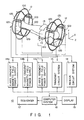
- Fig. 1 is a grammatical representation of a nuclear magnetic resonance imaging apparatus embodying the present invention.
- the magnetic resonance imaging apparatus which is generally indicated at 10, includes gradient magnetic field forming coils 12 for forming gradient magnetic fields adapted to acquire information on the position of a body portion of a subject under examination 100 in which magnetic resonance signals are induced and a radio-frequency coil 13 responsive to application of a radio-frequency pulse thereto for radiating to the subject a radio-frequency magnetic field adapted to induce the magnetic resonance signals and for detecting the induced magnetic resonance signals.
- the gradient magnetic field forming coils 12 comprise a X-axis gradient magnetic field forming coil 12a for forming a gradient magnetic field in the X-axis direction, a Y-axis gradient magnetic field forming coil 12b for forming a gradient magnetic field in the Y-axis direction and a Z-axis gradient magnetic field forming coil 12c for forming a gradient magnetic field in the Z-axis direction.
- the gradient magnetic field forming coils 12a, 12b and 12c are connected to an X-axis gradient magnetic field power supply 14a, a Y-axis gradient magnetic field power supply 14b and a Z-axis gradient magnetic field power supply 14c, respectively.
- the radio-frequency coil 13 is connected to a transmit circuit system 15 and a receive circuit system 16.
- the apparatus 10 is further provided with a sequencer 17 for practicing an imaging pulse sequence and a computer system 18 for controlling all of the power supplies 14a, 14b and 14c, the transmit circuit system 15, the receive circuit system 16 and the sequencer and processing the detected NMR signals. Signals processed by the computer system 18 are displayed on a display 19.
- the apparatus is provided with a static magnetic field forming coil (refer to Fig. 2) for applying a static magnetic field to the subject 100 in the Z-axis direction and a power supply (not shown) for supplying the static magnetic field forming coil with current as well.
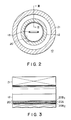
- a cylindrical radio-frequency shielding body 20 adapted for interrupting electromagnetic coupling between the gradient magnetic field forming coils 12 and the radio-frequency coil 13 due to a radio-frequency pulse applied to the radio-frequency coil 13.
- like reference numerals are used to designate corresponding parts to those in Fig. 1.
- Reference numeral 21 designates the static magnetic field coil adapted to form a static magnetic field along the Z-axis direction of the subject 100 of Fig. 1.
- the radio-frequency shielding body 20 consists of copper layers 20B1 and 20B2 plated on both sides of a base 20. This structure permits the radio-frequency shielding body 20 of a thickness less than the skin depth to be obtained.
- the radio-frequency shielding body may be formed of a conductive layer formed on the surface of a sheet of insulating material. Also, an evaporated film may be used as the radio-frequency shielding body. In addition, it is desirable that the radio-frequency shielding body 20 have a thickness from 5 to 10 ⁇ which can be manufactured.
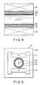
- the apparatus shown in Fig. 4 includes a transversal magnetic field forming electromagnet 30 for use as the static magnetic field forming device.
- a desired one may be selected from among various types of electromagnets such as a solenoid coil type magnet, a solenoid coil type superconducting magnet, a Helmholtz type electromagnet, etc.
- the electromagnet 30 has cylindrical space therein.
- a static magnetic field Bo is produced in the cylindrical space.
- a cylindrical gradient magnetic field forming coil 12 is disposed in the cylindrical space.
- a whole-body transmit and receive radio-frequency coil 31 is disposed inside the cylindrical gradient magnetic field coil 12.
- a radio-frequency shielding body 32 formed in the shape of a cylinder is disposed between the cylindrical gradient magnetic field coil 12 and the whole-body transmit and receive radio-frequency coil 31.
- This radio-frequency shielding body 32 is substantially the same as that illustrated in Fig. 2.
- the apparatus shown in Fig. 5 includes a longitudinal magnetic field forming magnet 40 as the static magnetic field forming device.
- the magnet 40 a desired one may be selected from among various types of magnets such as a permanent magnet, an ordinary electromagnet, a superconducting magnet, etc.
- the magnet 40 has first and second magnetic poles 41 and 42 which face each other and are attached to a yoke 40A.
- a static magnetic field Bo is formed in the space between the first and second magnetic poles 41 and 42.
- a gradient magnetic field coil 43 is disposed in the space between the first and second magnetic poles.
- a whole-body transmit and receive radio-frequency coil 44 is disposed inside the gradient magnetic field coil 43.
- a radio-frequency shielding body 45 formed in the shape of a cylinder is disposed between the gradient magnetic field coil 43 and the whole-body transmit and receive radio-frequency coil 44.
- This radio-frequency shielding body 45 is substantially the same as that illustrated in Fig. 2.
- a magnetic resonance imaging apparatus can be provided which is provided with a radio-frequency shielding body that is simple in construction and permits electromagnetic coupling between a gradient magnetic field coil and a radio-frequency coil due to a radio-frequency pulse applied to the radio-frequency coil to be interrupted sufficiently so as not to deteriorate the rising and falling characteristics of gradient magnetic fields.
Abstract
Description
- The present invention relates to a magnetic resonance imaging apparatus employing nuclear magnetic resonance (NMR) phenomena and, more particularly, to a magnetic resonance imaging apparatus with an improved radio-frequency shielding body.
- The nuclear magnetic resonance is a phenomenon in which atomic nuclei placed in magnetic fields absorb electromagnetic energy at specific frequencies and then emit the energy as electromagnetic waves. A diagnostic apparatus employing the phenomenon senses electromagnetic waves emitted by the atomic nuclei, protons in particular, and processes received signals to obtain diagnostic information of a subject under examination, such as a tomographic image, which contains the atomic nucleus density (the proton density in particular), the longitudinal spin-lattice relaxation time T1, the transversal spin-lattice relaxation time T2, flow, chemical shifts and so on.
- The magnetic resonance imaging apparatus for obtaining cross-sectional NMR images of a subject under examination is provided with gradient magnetic field forming coils for forming gradient magnetic fields which serve to obtain position information of a body portion in which magnetic resonance signals are induced and a radio-frequency coil responsive to application of a radio-frequency pulse thereto for radiating a radio-frequency magnetic field serving to induce the magnetic resonance signals in the body portion and detecting the induced magnetic resonance signals. Between the gradient magnetic field forming coils and the radio-frequency coil is disposed a radio-frequency shielding body for interrupting electromagnetic coupling between the gradient magnetic field forming coils and the radio-frequency coil due to the radio-frequency pulse applied to the radio-frequency coil.
- The radio-frequency shielding body is generally formed of metallic foil made of a good conductor such as copper. However, eddy currents will be induced in the surface of the radio-frequency shielding body by time-varying gradient magnetic fields formed by the gradient magnetic field forming coils. A problem arises due to the eddy currents in that the rising and falling characteristics of the gradient magnetic fields are deteriorated. As a result, resulting cross-sectional NMR images will have poor quality.
- In order to solve the problem with the radio-frequency shielding body, an approach has been proposed in Japanese Unexamined Patent Publication No. 60-177249 according to which metallic foil consisting of first and second conductive regions separated by a relatively narrow nonconductive region, such as a slit, is used to form the radio-frequency shielding body.
- Other techniques have been proposed in Japanese Unexamined Patent Publication No. 62-334. That is to say, a metal cylinder, which forms a radio-frequency shielding body, is provided with a lengthwise slit so as to decrease eddy currents by confining them locally or a metal cylinder is formed of plural pieces of metallic foil connected by insulating materials or dielectric materials so as to reduce impedance of a radio-frequency shielding body to a radio-frequency pulse and to thereby reduce undesirable electromagnetic coupling between the gradient magnetic field coils and the radio-frequency coil.
- However, such a radio-frequency shielding body is complex in structure and costly because of the provision of the metallic foil with a slit or interposition of a insulating material or dielectric material between pieces of metallic foil.
- According to still another proposal in Japanese Unexamined Patent Publication No. 63-290554, the radio-frequency shielding body is formed of a metal cylinder made of copper foil having a thickens not less than the skin depth. The skin depth is the depth in the direction to the center of the cylinder at which the amplitude of electromagnetic waves decays to 1/e (e= 2.718.., the base of the natural logarithm). More specifically, when electromagnetic waves with the Larmor frequency of protons penetrate into a cylinder made of some metal by a depth of δ in the direction to the center of the cylinder, if the amplitude of all the electromagnetic waves decays to 1/e at the depth δ, then the skin depth is defined as δ.
- In the case of a radio-frequency shielding body with a thickness less than the skin depth, the time constant of eddy currents can be made small so that the time it takes for eddy currents to dissipate is effectively shortened. However, the technique disclosed in the Publication, which is directed to a radio-frequency shielding body made of a metal cylinder, implies that it is impossible to make a radio-frequency shielding body having a thickness less than the skin depth.
- As described above, the conventional radio-frequency shielding bodies are complex in structure and costly.
- It is therefore an object of the present invention to provide a magnetic resonance imaging apparatus which is provided with a radio-frequency shielding body which is simple in construction and sufficiently interrupts electromagnetic coupling between gradient magnetic field forming coils and a radio-frequency coil due to a radio-frequency pulse applied to the radio-frequency coil so as not to deteriorate the rising and falling characteristics of gradient magnetic fields.
- The object of the present invention is attained by the following magnetic resonance imaging apparatus.
- In a magnetic resonance imaging apparatus comprising:
- static magnetic field generating means for generating a static magnetic field along the direction of a first axis;
- gradient magnetic field generating coil means for generating gradient magnetic fields along the direction of said first axis and the directions of second and third axes orthogonal to said first axis;
- a radio-frequency coil means for transmitting or receiving electromagnetic waves from a direction other than the direction of said first axis; and
- a radio-frequency shielding body disposed between said gradient magnetic field generating coil means and said radio-frequency coil means and having a thickness along the directions of said second and third axes,
- the improvement wherein said radio-frequency shielding body being arranged to interrupt electromagnetic coupling between said gradient magnetic field generating coil means and said radio-frequency coil means resulting from a radio-frequency pulse applied to said radio-frequency coil means and reduce a time constant of eddy currents generated in the surface of said gradient magnetic field coil means.
- Also, the object of the present invention is attained by the following magnetic resonance imaging apparatus.
- In a magnetic resonance imaging apparatus comprising a static magnetic field generating coil for generating a static magnetic field which is applied to a subject under examination, gradient magnetic field generating coils for generating gradient magnetic fields used to obtain information on the position of a body portion of the subject in which magnetic resonance signals are induced, a radio-frequency coil responsive to application of a radio-frequency pulse thereto for transmitting a radio-frequency magnetic field adapted to induce the magnetic resonance signals and for detecting the induced magnetic resonance signals and a radio-frequency shielding body disposed between said gradient magnetic field generating coils and said radio-frequency coil for interrupting electromagnetic coupling between said gradient magnetic field generating coils and said radio-frequency coil due to said radio-frequency pulse applied to said radio-frequency coil,
- the improvement wherein said radio-frequency shielding body is formed of a conductive material having a thickness less than the skin depth defined by

- With the magnetic resonance imaging apparatus of the present invention, since the radio-frequency shielding body is formed of a conductive material having a thickness less than

- This invention can be more fully understood from the following detailed description when taken in conjunction with the accompanying drawings, in which:
- Fig. 1
- is a diagrammatic representation of a magnetic resonance imaging apparatus of the present invention;
- Fig. 2
- is a cross-sectional view illustrating a radio-frequency shielding coil of the present invention;
- Fig. 3
- is a sectional view taken along the line III-III of Fig. 2;
- Fig. 4
- is a sectional view of a radio-frequency shielding body according to another embodiment of the present invention; and
- Fig. 5
- is a sectional view of a radio-frequency shielding body according to still another embodiment of the present invention.
- Hereinafter the embodiments of the present invention will be described with reference to the drawings. Fig. 1 is a grammatical representation of a nuclear magnetic resonance imaging apparatus embodying the present invention.
- As illustrated in Fig. 1, the magnetic resonance imaging apparatus, which is generally indicated at 10, includes gradient magnetic
field forming coils 12 for forming gradient magnetic fields adapted to acquire information on the position of a body portion of a subject underexamination 100 in which magnetic resonance signals are induced and a radio-frequency coil 13 responsive to application of a radio-frequency pulse thereto for radiating to the subject a radio-frequency magnetic field adapted to induce the magnetic resonance signals and for detecting the induced magnetic resonance signals. More specifically, with the lengthwise axis of the subject underexamination 100 taken as the Z axis and the axes orthogonal to the Z axis taken as the X and Y axes, the gradient magneticfield forming coils 12 comprise a X-axis gradient magneticfield forming coil 12a for forming a gradient magnetic field in the X-axis direction, a Y-axis gradient magneticfield forming coil 12b for forming a gradient magnetic field in the Y-axis direction and a Z-axis gradient magnetic field forming coil 12c for forming a gradient magnetic field in the Z-axis direction. The gradient magneticfield forming coils field power supply 14b and a Z-axis gradient magnetic field power supply 14c, respectively. The radio-frequency coil 13 is connected to atransmit circuit system 15 and areceive circuit system 16. - The
apparatus 10 is further provided with a sequencer 17 for practicing an imaging pulse sequence and acomputer system 18 for controlling all of thepower supplies 14a, 14b and 14c, thetransmit circuit system 15, thereceive circuit system 16 and the sequencer and processing the detected NMR signals. Signals processed by thecomputer system 18 are displayed on adisplay 19. The apparatus is provided with a static magnetic field forming coil (refer to Fig. 2) for applying a static magnetic field to thesubject 100 in the Z-axis direction and a power supply (not shown) for supplying the static magnetic field forming coil with current as well. - As illustrated in Fig. 2, on the inside of the gradient magnetic
field forming coils 12 of theapparatus 10 is mounted a cylindrical radio-frequency shielding body 20 adapted for interrupting electromagnetic coupling between the gradient magneticfield forming coils 12 and the radio-frequency coil 13 due to a radio-frequency pulse applied to the radio-frequency coil 13. In Fig. 2, like reference numerals are used to designate corresponding parts to those in Fig. 1.Reference numeral 21 designates the static magnetic field coil adapted to form a static magnetic field along the Z-axis direction of thesubject 100 of Fig. 1. - The radio-
frequency shielding body 20 for use in the apparatus consists of copper-plated metal which is about 10 µm in thickness and formed on the surface of a base consisting of an organic fiber textile made of, for example, polyester cloth. Since the radio-frequency shielding body 20 is thinner than the skin depth of 30 µ which is represented by
field forming coils 12 will not be deteriorated. - As illustrated in Fig. 3, the radio-
frequency shielding body 20 consists of copper layers 20B1 and 20B2 plated on both sides of abase 20. This structure permits the radio-frequency shielding body 20 of a thickness less than the skin depth to be obtained. - Besides the above embodiment, the radio-frequency shielding body may be formed of a conductive layer formed on the surface of a sheet of insulating material. Also, an evaporated film may be used as the radio-frequency shielding body. In addition, it is desirable that the radio-
frequency shielding body 20 have a thickness from 5 to 10 µ which can be manufactured. - Next, another embodiment of the magnetic resonance imaging apparatus of the present invention will be described with reference to Fig. 4. The apparatus shown in Fig. 4 includes a transversal magnetic
field forming electromagnet 30 for use as the static magnetic field forming device. As the transversal magnetic field forming electromagnet 30 a desired one may be selected from among various types of electromagnets such as a solenoid coil type magnet, a solenoid coil type superconducting magnet, a Helmholtz type electromagnet, etc. Theelectromagnet 30 has cylindrical space therein. A static magnetic field Bo is produced in the cylindrical space. A cylindrical gradient magneticfield forming coil 12 is disposed in the cylindrical space. A whole-body transmit and receive radio-frequency coil 31 is disposed inside the cylindrical gradientmagnetic field coil 12. Furthermore, a radio-frequency shielding body 32 formed in the shape of a cylinder is disposed between the cylindrical gradientmagnetic field coil 12 and the whole-body transmit and receive radio-frequency coil 31. This radio-frequency shielding body 32 is substantially the same as that illustrated in Fig. 2. - Next, still another embodiment of the magnetic resonance imaging apparatus of the present invention will be described with reference to Fig. 5. The apparatus shown in Fig. 5 includes a longitudinal magnetic
field forming magnet 40 as the static magnetic field forming device. As the magnet 40 a desired one may be selected from among various types of magnets such as a permanent magnet, an ordinary electromagnet, a superconducting magnet, etc. Themagnet 40 has first and secondmagnetic poles 41 and 42 which face each other and are attached to ayoke 40A. A static magnetic field Bo is formed in the space between the first and secondmagnetic poles 41 and 42. A gradientmagnetic field coil 43 is disposed in the space between the first and second magnetic poles. A whole-body transmit and receive radio-frequency coil 44 is disposed inside the gradientmagnetic field coil 43. Furthermore, a radio-frequency shielding body 45 formed in the shape of a cylinder is disposed between the gradientmagnetic field coil 43 and the whole-body transmit and receive radio-frequency coil 44. This radio-frequency shielding body 45 is substantially the same as that illustrated in Fig. 2. - As can be seen from the foregoing, according to the present invention, a magnetic resonance imaging apparatus can be provided which is provided with a radio-frequency shielding body that is simple in construction and permits electromagnetic coupling between a gradient magnetic field coil and a radio-frequency coil due to a radio-frequency pulse applied to the radio-frequency coil to be interrupted sufficiently so as not to deteriorate the rising and falling characteristics of gradient magnetic fields.
Claims (18)
- In a magnetic resonance imaging apparatus comprising:
static magnetic field generating means (21) for generating a static magnetic field along the direction of a first axis;
gradient magnetic field generating coil 12 (12a, 12b, 12c) means for generating gradient magnetic fields along the direction of said first axis and the directions of second and third axes orthogonal to said first axis;
a radio-frequency coil means (13) for transmitting or receiving electromagnetic waves from a direction other than the direction of said first axis; and
a radio-frequency shielding body (20) disposed between said gradient magnetic field generating coil means 12 (12a, 12b, 12c) and said radio-frequency coil means (13) and having a thickness along the directions of said second and third axes,
characterized in that said radio-frequency shielding body (20) is arranged to interrupt electromagnetic coupling between said gradient magnetic field generating coil means 12, (12a, 12b, 12c) and said radio-frequency coil means (13) resulting from a radio-frequency pulse applied to said radio-frequency coil means (13) and reduce a time constant of eddy currents generated in the surface of said gradient magnetic field coil means 12 (12a, 12b, 12c). - A magnetic resonance imaging apparatus according to claim 1, characterized in that said radio-frequency shielding body (20) is formed of a conductive material having a thickness less than the skin depth.
- A magnetic resonance imaging apparatus according to claim 2, characterized in that the skin depth is defined by

- A magnetic resonance imaging apparatus according to claim 1, characterized in that said radio-frequency shielding body (20) is exchanged according to types of atomic nuclei of imaging objects.
- A magnetic resonance imaging apparatus according to claim 1, characterized in that said radio-frequency shielding body (20) is disposed close to the radio-frequency coil side of said gradient magnetic field generating coil means 12 (12a, 12b, 12c).
- A magnetic resonance imaging apparatus according to claim 5, characterized in that said radio-frequency shielding body (20) has a shape similar to that of said gradient magnetic field generating coil means 12 (12a, 12b, 12c).
- A magnetic resonance imaging apparatus according to claim 1, characterized in that said radio-frequency shielding body (20) has a sectional structure in which a conductive layer is formed on a sheet of insulating material.
- A magnetic resonance imaging apparatus according to claim 1, characterized in that said radio-frequency shielding body (20) has a sectional structure in which an organic fiber textile is plated with a metal.
- A magnetic resonance imaging apparatus according to claim 8, characterized in that said organic fiber is made of polyester.
- A magnetic resonance imaging apparatus according to claim 8, characterized in that said metal is copper.
- A magnetic resonance imaging apparatus according to claim 1, characterized in that said radio-frequency coil means (13) is a whole-body transmit and receive coil which is disposed coaxially with said gradient magnetic field generating coil means 12 (12a, 12b, 12c).
- A magnetic resonance imaging apparatus according to claim 1, characterized in that said radio-frequency coil means (13) is a transmit and/or receive coil which is disposed inside said gradient magnetic field coil means 12 (12a, 12b, 12c) with a space between them.
- A magnetic resonance imaging apparatus according to claim 1, characterized in that said radio-frequency coil means (13) comprises a whole-body transmit and receive coil which is disposed coaxially with said gradient magnetic field generating coil means 12 (12a, 12b, 12c) and a transmit and/or receive coil which is disposed inside said gradient magnetic field coil means 12 (12a, 12b, 12c) with a space between them.
- A magnetic resonance imaging apparatus according to claim 1, characterized in that said static magnetic field generating means (21) comprises an electromagnet for generating a static magnetic field horizontally.
- A magnetic resonance imaging apparatus according to claim 1, characterized in that said static magnetic field generating means (21) comprises an electromagnet for generating a static magnetic field vertically.
- A magnetic resonance imaging apparatus according to claim 1, characterized in that said static magnetic field generating means (21) comprises a permanent magnet for generating a static magnetic field horizontally.
- A magnetic resonance imaging apparatus according to claim 1, characterized in that said static magnetic field generating means (21) comprises a permanent magnet for generating a static magnetic field vertically.
- In a magnetic resonance imaging apparatus comprising a static magnetic field generating coil (21) for generating a static magnetic field which is applied to a subject under examination, gradient magnetic field generating coils 12 (12a, 12b, 12c) for generating gradient magnetic fields used to obtain information on the position of a body portion of the subject in which magnetic resonance signals are induced, a radio-frequency coil (13) responsive to application of a radio-frequency pulse thereto for transmitting a radio-frequency magnetic field adapted to induce the magnetic resonance signals and for detecting the induced magnetic resonance signals and a radio-frequency shielding body (20) disposed between said gradient magnetic field generating coils 12 (12a, 12b, 12c) and said radio-frequency coil (13) for interrupting electromagnetic coupling between said gradient magnetic field generating coils 12 (12a, 12b, 12c) and said radio-frequency coil (13) due to said radio-frequency pulse applied to said radio-frequency coil (13),
characterized in that said radio-frequency shielding body (20) is formed of a conductive material having a thickness less than the skin depth defined by
Applications Claiming Priority (2)
| Application Number | Priority Date | Filing Date | Title |
|---|---|---|---|
| JP1308547A JP2823278B2 (en) | 1989-11-28 | 1989-11-28 | Magnetic resonance imaging equipment |
| JP308547/89 | 1989-11-28 |
Publications (3)
| Publication Number | Publication Date |
|---|---|
| EP0430104A2 true EP0430104A2 (en) | 1991-06-05 |
| EP0430104A3 EP0430104A3 (en) | 1991-10-30 |
| EP0430104B1 EP0430104B1 (en) | 1998-04-15 |
Family
ID=17982343
Family Applications (1)
| Application Number | Title | Priority Date | Filing Date |
|---|---|---|---|
| EP90122419A Expired - Lifetime EP0430104B1 (en) | 1989-11-28 | 1990-11-23 | Magnetic resonance imaging apparatus |
Country Status (3)
| Country | Link |
|---|---|
| EP (1) | EP0430104B1 (en) |
| JP (1) | JP2823278B2 (en) |
| DE (1) | DE69032243T2 (en) |
Cited By (9)
| Publication number | Priority date | Publication date | Assignee | Title |
|---|---|---|---|---|
| DE4326516A1 (en) * | 1992-08-06 | 1994-02-10 | Hitachi Ltd | High frequency probe for NMR imaging equipment - contains transmit-receive coils for feeding HF power to coaxial hollow cylindrical resonators bridged by figure-of-eight coils to eliminate coupling |
| EP2163912A2 (en) * | 2008-09-11 | 2010-03-17 | Allegheny-Singer Research Institute | Hybrid MRI |
| US7999544B2 (en) | 2007-04-11 | 2011-08-16 | Allegheny-Singer Research Institute | Rapid MRI dynamic imaging using mach |
| WO2012025860A1 (en) | 2010-08-25 | 2012-03-01 | Koninklijke Philips Electronics N.V. | Rf shield for mri comprising conductive coating as shielding material |
| US8131046B2 (en) | 2008-10-29 | 2012-03-06 | Allegheny-Singer Research Institute | Magnetic resonance imager using cylindrical offset region of excitation, and method |
| US8198892B2 (en) | 2009-04-22 | 2012-06-12 | Allegheny-Singer Research Institute | Steady-state-free-precession (SSFP) magnetic resonance imaging (MRI) and method |
| US8219176B2 (en) | 2007-03-08 | 2012-07-10 | Allegheny-Singer Research Institute | Single coil parallel imaging |
| US8405394B2 (en) | 2009-10-20 | 2013-03-26 | Allegheny-Singer Research Institute | Targeted acquisition using holistic ordering (TACHO) approach for high signal to noise imaging |
| US8688193B2 (en) | 2008-06-26 | 2014-04-01 | Allegheny-Singer Research Institute | Magnetic resonance imager, method and program which continuously applies steady-state free precession to k-space |
Families Citing this family (2)
| Publication number | Priority date | Publication date | Assignee | Title |
|---|---|---|---|---|
| US7102350B2 (en) | 2004-06-30 | 2006-09-05 | General Electric Company | Shielding apparatus for magnetic resonance imaging |
| JP5379993B2 (en) * | 2007-05-18 | 2013-12-25 | 株式会社東芝 | Magnetic resonance imaging system |
Citations (6)
| Publication number | Priority date | Publication date | Assignee | Title |
|---|---|---|---|---|
| DE3445724A1 (en) * | 1983-12-15 | 1985-06-27 | Mitsubishi Denki K.K., Tokio/Tokyo | MAGNETIC FIELD COIL FOR AN NMR COMPUTER TOMOGRAPH |
| EP0151726A2 (en) * | 1983-12-16 | 1985-08-21 | General Electric Company | A shield for decoupling RF and gradient coils in an NMR apparatus |
| DE3621107A1 (en) * | 1985-06-26 | 1987-01-08 | Toshiba Kawasaki Kk | MAGNETIC RESONANCE IMAGING DEVICE |
| JPS63290554A (en) * | 1987-05-21 | 1988-11-28 | Yokogawa Medical Syst Ltd | Rf shield of nmr imaging apparatus |
| US4879515A (en) * | 1988-12-22 | 1989-11-07 | General Electric Company | Double-sided RF shield for RF coil contained within gradient coils of NMR imaging device |
| US4924184A (en) * | 1988-04-11 | 1990-05-08 | Mitsubishi Denki Kabushiki Kaisha | Magnetic resonance apparatus |
-
1989
- 1989-11-28 JP JP1308547A patent/JP2823278B2/en not_active Expired - Lifetime
-
1990
- 1990-11-23 EP EP90122419A patent/EP0430104B1/en not_active Expired - Lifetime
- 1990-11-23 DE DE69032243T patent/DE69032243T2/en not_active Expired - Fee Related
Patent Citations (6)
| Publication number | Priority date | Publication date | Assignee | Title |
|---|---|---|---|---|
| DE3445724A1 (en) * | 1983-12-15 | 1985-06-27 | Mitsubishi Denki K.K., Tokio/Tokyo | MAGNETIC FIELD COIL FOR AN NMR COMPUTER TOMOGRAPH |
| EP0151726A2 (en) * | 1983-12-16 | 1985-08-21 | General Electric Company | A shield for decoupling RF and gradient coils in an NMR apparatus |
| DE3621107A1 (en) * | 1985-06-26 | 1987-01-08 | Toshiba Kawasaki Kk | MAGNETIC RESONANCE IMAGING DEVICE |
| JPS63290554A (en) * | 1987-05-21 | 1988-11-28 | Yokogawa Medical Syst Ltd | Rf shield of nmr imaging apparatus |
| US4924184A (en) * | 1988-04-11 | 1990-05-08 | Mitsubishi Denki Kabushiki Kaisha | Magnetic resonance apparatus |
| US4879515A (en) * | 1988-12-22 | 1989-11-07 | General Electric Company | Double-sided RF shield for RF coil contained within gradient coils of NMR imaging device |
Non-Patent Citations (1)
| Title |
|---|
| PATENT ABSTRACTS OF JAPAN, vol. 13, no. 115 (C-578)[3463], 20th March 1989; & JP-A-63 290 554 (YOKOGAWA MEDICAL SYSTEMS LTD) 28-11-1988 * |
Cited By (13)
| Publication number | Priority date | Publication date | Assignee | Title |
|---|---|---|---|---|
| US5453692A (en) * | 1992-08-06 | 1995-09-26 | Hitachi, Ltd. | RF probe for nuclear magnetic resonance imaging (MRI) devices |
| DE4326516C2 (en) * | 1992-08-06 | 1998-02-05 | Hitachi Ltd | Radio frequency probe for MRI devices |
| DE4326516A1 (en) * | 1992-08-06 | 1994-02-10 | Hitachi Ltd | High frequency probe for NMR imaging equipment - contains transmit-receive coils for feeding HF power to coaxial hollow cylindrical resonators bridged by figure-of-eight coils to eliminate coupling |
| US8219176B2 (en) | 2007-03-08 | 2012-07-10 | Allegheny-Singer Research Institute | Single coil parallel imaging |
| US7999544B2 (en) | 2007-04-11 | 2011-08-16 | Allegheny-Singer Research Institute | Rapid MRI dynamic imaging using mach |
| US8688193B2 (en) | 2008-06-26 | 2014-04-01 | Allegheny-Singer Research Institute | Magnetic resonance imager, method and program which continuously applies steady-state free precession to k-space |
| EP2163912A2 (en) * | 2008-09-11 | 2010-03-17 | Allegheny-Singer Research Institute | Hybrid MRI |
| EP2163912A3 (en) * | 2008-09-11 | 2010-11-24 | Allegheny-Singer Research Institute | Hybrid MRI |
| US8131046B2 (en) | 2008-10-29 | 2012-03-06 | Allegheny-Singer Research Institute | Magnetic resonance imager using cylindrical offset region of excitation, and method |
| US8198892B2 (en) | 2009-04-22 | 2012-06-12 | Allegheny-Singer Research Institute | Steady-state-free-precession (SSFP) magnetic resonance imaging (MRI) and method |
| US8405394B2 (en) | 2009-10-20 | 2013-03-26 | Allegheny-Singer Research Institute | Targeted acquisition using holistic ordering (TACHO) approach for high signal to noise imaging |
| WO2012025860A1 (en) | 2010-08-25 | 2012-03-01 | Koninklijke Philips Electronics N.V. | Rf shield for mri comprising conductive coating as shielding material |
| US9417301B2 (en) | 2010-08-25 | 2016-08-16 | Koninklijke Philips N.V. | RF shield for MRI comprising conductive coating as shielding material |
Also Published As
| Publication number | Publication date |
|---|---|
| EP0430104A3 (en) | 1991-10-30 |
| DE69032243D1 (en) | 1998-05-20 |
| JP2823278B2 (en) | 1998-11-11 |
| JPH03168122A (en) | 1991-07-19 |
| EP0430104B1 (en) | 1998-04-15 |
| DE69032243T2 (en) | 1998-12-17 |
Similar Documents
| Publication | Publication Date | Title |
|---|---|---|
| EP0231879B1 (en) | Self-shielded gradient coils for nuclear magnetic resonance imaging | |
| EP0359374B1 (en) | Magnetic resonance apparatus | |
| US5304932A (en) | Apparatus and method for shielding MRI RF antennae from the effect of surrounding objects | |
| EP0084946B1 (en) | Apparatus for generating or detecting field components in a magnetic resonance system | |
| JP4173236B2 (en) | Magnetic resonance tomography system | |
| US4733189A (en) | Magnetic resonance imaging systems | |
| EP0629875B1 (en) | Magnetic resonance gradient coil and RF screen | |
| US4980641A (en) | Method and apparatus of reducing magnetic hysteresis in MRI systems | |
| EP0430104B1 (en) | Magnetic resonance imaging apparatus | |
| JPS61226029A (en) | Coils apparatus for nuclear magnetic resonance examination | |
| US5568051A (en) | Magnetic resonance imaging apparatus having superimposed gradient coil | |
| US7786730B2 (en) | NMR machine comprising solenoid gradient coils which are incorporated into tubes | |
| US4870363A (en) | Apparatus for creating a magnetic field gradient and the examination of a surface layer of a body | |
| US5804968A (en) | Gradient coils with reduced eddy currents | |
| JPH0824240A (en) | Magnetic resonance image pickup device | |
| US5381093A (en) | Magnetic resonance imaging apparatus | |
| US7279898B2 (en) | MRI RF surface coil with reduced sensitivity in proximity of conductors | |
| EP1440325B1 (en) | Radio-frequency coil with two parallel end conductors | |
| WO1994001785A1 (en) | Solenoidal, octopolar, transverse gradient coils | |
| JP3866960B2 (en) | Magnetic resonance imaging device | |
| JP3092106B2 (en) | Magnetic resonance imaging equipment | |
| Masouridis et al. | Design and implementation of solenoid and Alderman-Grant coils for magnetic resonance microscopy at 7T | |
| JP3496891B2 (en) | Nuclear magnetic resonance imaging equipment | |
| JPH07255700A (en) | Rf coil for mri | |
| JPH0884712A (en) | Superconducting magnet apparatus and magnetic resonance imaging apparatus using the same |
Legal Events
| Date | Code | Title | Description |
|---|---|---|---|
| PUAI | Public reference made under article 153(3) epc to a published international application that has entered the european phase |
Free format text: ORIGINAL CODE: 0009012 |
|
| 17P | Request for examination filed |
Effective date: 19901123 |
|
| AK | Designated contracting states |
Kind code of ref document: A2 Designated state(s): DE GB |
|
| PUAL | Search report despatched |
Free format text: ORIGINAL CODE: 0009013 |
|
| AK | Designated contracting states |
Kind code of ref document: A3 Designated state(s): DE GB |
|
| 17Q | First examination report despatched |
Effective date: 19950509 |
|
| GRAG | Despatch of communication of intention to grant |
Free format text: ORIGINAL CODE: EPIDOS AGRA |
|
| GRAG | Despatch of communication of intention to grant |
Free format text: ORIGINAL CODE: EPIDOS AGRA |
|
| GRAH | Despatch of communication of intention to grant a patent |
Free format text: ORIGINAL CODE: EPIDOS IGRA |
|
| GRAH | Despatch of communication of intention to grant a patent |
Free format text: ORIGINAL CODE: EPIDOS IGRA |
|
| GRAA | (expected) grant |
Free format text: ORIGINAL CODE: 0009210 |
|
| AK | Designated contracting states |
Kind code of ref document: B1 Designated state(s): DE GB |
|
| REF | Corresponds to: |
Ref document number: 69032243 Country of ref document: DE Date of ref document: 19980520 |
|
| PLBE | No opposition filed within time limit |
Free format text: ORIGINAL CODE: 0009261 |
|
| STAA | Information on the status of an ep patent application or granted ep patent |
Free format text: STATUS: NO OPPOSITION FILED WITHIN TIME LIMIT |
|
| 26N | No opposition filed | ||
| REG | Reference to a national code |
Ref country code: GB Ref legal event code: IF02 |
|
| PGFP | Annual fee paid to national office [announced via postgrant information from national office to epo] |
Ref country code: DE Payment date: 20071115 Year of fee payment: 18 |
|
| PGFP | Annual fee paid to national office [announced via postgrant information from national office to epo] |
Ref country code: GB Payment date: 20071121 Year of fee payment: 18 |
|
| GBPC | Gb: european patent ceased through non-payment of renewal fee |
Effective date: 20081123 |
|
| PG25 | Lapsed in a contracting state [announced via postgrant information from national office to epo] |
Ref country code: DE Free format text: LAPSE BECAUSE OF NON-PAYMENT OF DUE FEES Effective date: 20090603 |
|
| PG25 | Lapsed in a contracting state [announced via postgrant information from national office to epo] |
Ref country code: GB Free format text: LAPSE BECAUSE OF NON-PAYMENT OF DUE FEES Effective date: 20081123 |