EP0436345A2 - Voice and image communicating apparatus - Google Patents
Voice and image communicating apparatus Download PDFInfo
- Publication number
- EP0436345A2 EP0436345A2 EP90313817A EP90313817A EP0436345A2 EP 0436345 A2 EP0436345 A2 EP 0436345A2 EP 90313817 A EP90313817 A EP 90313817A EP 90313817 A EP90313817 A EP 90313817A EP 0436345 A2 EP0436345 A2 EP 0436345A2
- Authority
- EP
- European Patent Office
- Prior art keywords
- calling party
- image
- memory
- image data
- data
- Prior art date
- Legal status (The legal status is an assumption and is not a legal conclusion. Google has not performed a legal analysis and makes no representation as to the accuracy of the status listed.)
- Granted
Links
Images


Classifications
-
- H—ELECTRICITY
- H04—ELECTRIC COMMUNICATION TECHNIQUE
- H04M—TELEPHONIC COMMUNICATION
- H04M1/00—Substation equipment, e.g. for use by subscribers
- H04M1/57—Arrangements for indicating or recording the number of the calling subscriber at the called subscriber's set
- H04M1/575—Means for retrieving and displaying personal data about calling party
- H04M1/576—Means for retrieving and displaying personal data about calling party associated with a pictorial or graphical representation
-
- H—ELECTRICITY
- H04—ELECTRIC COMMUNICATION TECHNIQUE
- H04M—TELEPHONIC COMMUNICATION
- H04M1/00—Substation equipment, e.g. for use by subscribers
- H04M1/26—Devices for calling a subscriber
- H04M1/27—Devices whereby a plurality of signals may be stored simultaneously
- H04M1/274—Devices whereby a plurality of signals may be stored simultaneously with provision for storing more than one subscriber number at a time, e.g. using toothed disc
- H04M1/2745—Devices whereby a plurality of signals may be stored simultaneously with provision for storing more than one subscriber number at a time, e.g. using toothed disc using static electronic memories, e.g. chips
- H04M1/27467—Methods of retrieving data
- H04M1/27475—Methods of retrieving data using interactive graphical means or pictorial representations
-
- H—ELECTRICITY
- H04—ELECTRIC COMMUNICATION TECHNIQUE
- H04M—TELEPHONIC COMMUNICATION
- H04M3/00—Automatic or semi-automatic exchanges
- H04M3/42—Systems providing special services or facilities to subscribers
- H04M3/42025—Calling or Called party identification service
- H04M3/42034—Calling party identification service
- H04M3/42042—Notifying the called party of information on the calling party
-
- H—ELECTRICITY
- H04—ELECTRIC COMMUNICATION TECHNIQUE
- H04N—PICTORIAL COMMUNICATION, e.g. TELEVISION
- H04N7/00—Television systems
- H04N7/14—Systems for two-way working
- H04N7/141—Systems for two-way working between two video terminals, e.g. videophone
- H04N7/147—Communication arrangements, e.g. identifying the communication as a video-communication, intermediate storage of the signals
-
- H—ELECTRICITY
- H04—ELECTRIC COMMUNICATION TECHNIQUE
- H04Q—SELECTING
- H04Q11/00—Selecting arrangements for multiplex systems
- H04Q11/04—Selecting arrangements for multiplex systems for time-division multiplexing
- H04Q11/0428—Integrated services digital network, i.e. systems for transmission of different types of digitised signals, e.g. speech, data, telecentral, television signals
- H04Q11/0435—Details
- H04Q11/0471—Terminal access circuits
-
- H—ELECTRICITY
- H04—ELECTRIC COMMUNICATION TECHNIQUE
- H04Q—SELECTING
- H04Q2213/00—Indexing scheme relating to selecting arrangements in general and for multiplex systems
- H04Q2213/091—Indication of kind/number of subscriber
-
- H—ELECTRICITY
- H04—ELECTRIC COMMUNICATION TECHNIQUE
- H04Q—SELECTING
- H04Q2213/00—Indexing scheme relating to selecting arrangements in general and for multiplex systems
- H04Q2213/171—Number indicating signals (no dial signals)
-
- H—ELECTRICITY
- H04—ELECTRIC COMMUNICATION TECHNIQUE
- H04Q—SELECTING
- H04Q2213/00—Indexing scheme relating to selecting arrangements in general and for multiplex systems
- H04Q2213/337—Picturephone
Definitions
- the present invention relates to a communicating apparatus which is connected to a network such as an ISDN or the like and executes a communication of a voice, an image, or the like and, more particularly, to a communicating apparatus for displaying a special image upon call reception.
- a television telephone set has been known as a multimedia communicating apparatus which can communicate a voice and an image.
- the above method has a problem such that a condition such that the calling party sends name information is used as a prerequisite and that a special adding apparatus is needed.
- Another object of the invention is to provide a communicating apparatus which can register an image regarding a calling party communicating apparatus by a simple construction without providing any special inputting apparatus.
- a communicating apparatus comprising: receiving means for receiving image data which was sent from a calling party communicating apparatus; memory means for storing the image data received by the receiving means in correspondence to ID data indicative of the calling party communicating apparatus; and display means for receiving the ID data upon call reception from the calling party communicating apparatus and for reading out the image data corresponding to the received ID data from the memory means and displaying.
- Another object of the invention is to provide a communicating apparatus with a simple construction in which just before a reception side responds to a reception call, image information regarding a calling party which will be effective if it is displayed on an image display apparatus on the reception side can previously been stored on the reception side by a simple operation.
- Still another object of the invention is to improve information regarding a calling party communicating apparatus which is displayed upon reception.
- a plurality of sheets of information regarding the calling party communicating apparatus are displayed simultaneously or as a moving image upon reception.
- Another object of the invention is to provide a communicating apparatus which can recognize a plurality of persons which use the apparatus of the same calling party number.
- Another object of the invention is to provide a communicating apparatus which can see the face of a person as a communication party upon reception.
- Another object of the invention is to provide a communicating apparatus in which information regarding a communication party is displayed upon reception and when the user doesn't want to communicate by checking the displayed information, a communication can be disconnected before data is received.
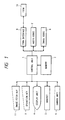
- Fig. 1 is a whole arrangement diagram of a television telephone set which is connected to the ISDN according to the first embodiment of the invention.
- reference numeral 1 denotes a control unit comprising a CPU for controlling the operation of the ISDN connected television telephone set, a ROM, and a RAM.
- a memory 2 is connected to the control unit 1.
- the following various apparatuses are connected to the control unit 1 through an I/O port (not shown).
- an operation key 3 for designating and inputting a calling party telephone number or the like upon calling or the like from this side of the television telephone
- an image display unit 4 comprising a CRT display for displaying image information which is sent from the calling party and the telephone number or the like of the calling party
- a handset 5 as a transceiver for transferring a voice
- a camera unit 6 for inputting an image on this side
- an audio codec 7 for executing the A/D and D/A conversions between a digital signal which is processed by the ISDN and an audio analog signal which is input/output to/from the handset 5
- an image codec 8 for executing the D/A conversion from the digital signal of the ISDN into the image analog signal of the display unit 4 and the A/D conversion from the image analog signal of the camera unit 6 into the digital signal of the ISDN
- an ISDN interface 9 for connecting an ISDN (integrated services digital network) 10 and the television telephone, respectively.
- an image fetch key 11 comprising a push switch is connected to the I/O port.
- the image fetch key 11 generates a command signal to store a calling side image such as a face of the person on the calling party side or the like into the memory 2 by a pushing operation.
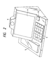
- Fig. 2 shows an external view of the television telephone set connected to the ISDN constructed as mentioned above.
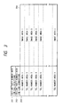
- Fig. 3 shows a part of a construction in the memory 2.
- the memory 2 is constructed by a volatile memory device comprising four areas 201 to 204.
- Reference numeral 201 denotes the calling party number area in call reception for storing the calling party telephone number (destination side telephone number) which is sent from the ISDN upon call reception (calling on the reception side) and 202 indicates the calling party number area in line connection for storing the calling party number when the line is connected, that is, while a speech is being executed.
- the calling party number which is sent from the ISDN is stored into the area 202.
- the calling party number which was input by using the operation key 3 is stored into the area 202.
- Reference numeral 203 represents n telephone number areas of Nos. 1 to n each for storing the telephone number.
- Reference numeral 204 indicates n image areas of Nos. 1 to n each for storing image information in correspondence to the areas in the area 203.
- the calling party number stored in the calling party number area 202 in line connection that is, the calling party number which is sent from the ISDN in the case of the call reception by calling from the calling party side or the calling party number which was input by the operation key 3 in the case of the calling from this side is read out.
- the calling party number in line connection is stored into the area 202 upon reception or key inputting operation.
- a pointer to designate an object to be compared is set into the top telephone number area of No. 1 in the area 203 (step S402).
- a check is made to see if the number information stored in the telephone number area of No. 1 coincides with the calling party number which was read out in step S401 or not (step S403). If NO in step S403, the pointer is sequentially moved to the next telephone number area (the telephone number area of No. 2 in this case) (step S404).
- step S405 a check is made to see if the comparison between the calling party number which had been read out in step S401 and all of the telephone numbers stored in the whole areas in which the telephone numbers had been stored in the telephone number area 203 has been completed or not.
- step S405 that is, if the comparison between the calling party number (i.e., destination side number) which was read out in step S401 and all of the telephone numbers in the whole areas in which the telephone numbers have been stored in the telephone number area 203 is not completed yet, the processing routine is returned to step S403. The processes in steps S403 to S405 are repeated.
- step S401 When the calling party number which was read out in step S401 coincides with the telephone number stored in any one of the areas of Nos. 1 to n in the telephone number area 203 (if YES in step S403), the image which had been received from the calling party through the ISDN and was displayed in the image display unit 4 is stored (step S406) into the image area corresponding to the telephone number area in which the coincident telephone number has been stored. The present program is finished. The execution of step S406 intends to change the image which has already been stored.
- step S405 If YES in step S405, that is, if the number corresponding to the calling party number which was read out in step S401 cannot be found out from all of the areas in the telephone number area 203, a check is made to see if a vacant area in which no telephone number is stored exists in the telephone number area 203 or not (step S407). If YES in step S407, the calling party number which was read out in step S401 is stored into the top area in the vacant area and the image information which was received from the calling party and displayed in the image display unit 4 is stored into the image area corresponding to the relevant area into which the calling party number was stored (step S408). The present program is finished.
- step S407 the storage contents of a predetermined set of areas in the telephone number area 203 are erased and the calling party number which was read out in step S401 and the image information displayed in the display unit 4 are respectively stored (updated) (step S409).
- the predetermined set of areas can be also changed in accordance with the order of the area numbers (1, 2, ..., n) every completion of the storing and updating processes.
- the image of the face of the person on the calling party side upon speech communication can be easily stored in correspondence to the calling party telephone number irrespective of the reception and transmission. That is, the calling party telephone number and the image information which is peculiar to the calling party are stored in correspondence to each set of the telephone number area 203 and the image area 204 corresponding thereto.
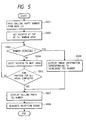
- the calling party number (i.e., destination number) stored in the calling party number area 201 in call reception, that is, the calling party number which is sent from the ISDN is read out.
- the calling party number is stored in the area 201.
- step S502 the pointer to designate an object to be compared is set into the top telephone number area of No. 1 in the telephone number area 203 (step S502).
- a check is made to see if the calling party number stored in the telephone number area of No. 1 coincides with the calling party number which was read out in step S501 or not (step S503). If NO in step S503, the pointer is sequentially moved to the next telephone number area (the telephone number area of No. 2 in this case) (step S504).
- step S505 a check is made to see if the comparison between the calling party number which had been read out in step S501 and all of the telephone numbers in the whole areas in which the telephone numbers had been stored in the telephone number area 203 has been completed or not.
- step S505 a check is made to see if the pointer has been moved to all of the telephone number areas in which the telephone numbers had been stored and the pointer has reached the telephone number area in which no telephone number is stored or there is no area to which the pointer moves (the pointer has already reached the last telephone number area of No. n) or not as a result of the movement of the pointer in step S504. If NO in step S505, that is, if the comparison between the calling party number which was read out in step S501 and all of the telephone numbers in the whole areas in which the telephone numbers have been stored in the telephone number area 203 is not completed yet, the processing routine is returned to step S503 and the processes in steps S503 to S505 are repeated.
- step S501 If the calling party number which was read out in step S501 coincides with the telephone number stored in any one of the areas in the telephone number area 203 (namely, if YES in step S503), the image information stored in the image area corresponding to the telephone number area in which the coincident telephone number has been stored is displayed in the display unit 4 (step S506) and the processing routine advances to step S507, which will be explained hereinlater.
- step S505 If YES in step S505, that is, if the number corresponding to the calling party number which was read out in step S501 cannot be found out from all of the areas in the telephone number area 203, only the calling party number which was informed from the ISDN is displayed in the display unit 4 (step S507). A reception sound to inform the call reception is generated (step S508) and the present program is finished.
- step S507 was executed after the image information had been displayed in step S506, both of the image information and the calling party number are displayed by the display unit 4.
- the calling partner can be easily presumed before response and the user can prepare for a response.
- the calling party number area 201 upon call reception and the calling party number area 202 in line connection have separately been provided in the memory 2.
- the invention is not necessarily limited to such a construction. The functions of both of those areas can be also performed by a single area.
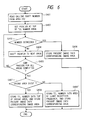
- step S409 in Fig. 4 in the embodiment can be also executed in the following manner. That is, the frequency of the reading and displaying operations due to the call reception of the image information of the corresponding image area is counted every area in the telephone number area 203 in the memory 2 and the area having the minimum frequency is used to store and update the calling party number and the image information corresponding to a command output from the image fetch key 11. That is, when the storage area of the image lacks, the storage image of a small frequency which is read out in response to the call reception is erased together with the corresponding telephone number, thereby updating to the new telephone number and image information.
- Fig. 6 shows a flowchart in this case.
- the image which is sent from the calling party has been used as image information.
- the image photographed by the camera unit 6 on this side can be also input as image information to the image area 204.
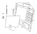
- the camera unit 6 for transmitting the image is also commonly used, there is no need to additionally provide another inputting means. For instance, a memorandum on which information such as process of a business talk with the calling party, thanks to a present from the calling party, name and family construction of the calling party, and the like was written is put up in front of the camera unit 6 as shown in Fig. 7 and the image fetch key 11 is depressed, thereby storing the image on the memorandum into the image area 204, and the calling party telephone number is stored into the corresponding area in the telephone number area 203 by the operation key 3.
- a program of a flowchart shown in Fig. 8 is executed. It is first instructed to input the calling party telephone number by the operation key 3.
- the image on the memorandum sheet is read as image information by the camera unit 6.
- the calling party telephone number and the image information are stored into the memory 2 in accordance with the same procedure as that of the processes in step S402 and subsequent steps in Fig. 4.
- the display upon call reception is executed in accordance with the same procedure as that shown in Fig. 5.
- the communicating apparatus comprises: the first memory for storing a calling party number from the ISDN upon call reception and for storing the calling party number (i.e., destination side number) in line connection; the second memory having a plurality of sets of telephone number areas and image areas respectively corresponding to the telephone number areas; the image fetching means for outputting a command to store image information which is displayed on the image display apparatus of the television telephone set into the second memory; and the control means for controlling in a manner such that the calling party number (destination side number) stored in the first memory and the image information displayed on the image display apparatus are respectively stored into either one of the plurality of sets of telephone number areas and image areas in the second memory in accordance with a command output from the image fetching means in the line connection and the calling party number stored in the first memory and the calling party numbers (destination side numbers) stored in the telephone number areas in the second memory are sequentially compared upon call reception from the ISDN
- the image information enough to presume the calling party can be previously stored on the reception side together with the corresponding telephone number by the simple operation. Therefore, just before the reception side responds to the call reception, the image information regarding the calling party, for instance, the face of the calling party or the like is displayed on the image display apparatus on the reception side and the calling party can be easily presumed.
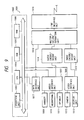
- Fig. 9 is a block arrangement diagram of a multimedia communicating apparatus which can communicate a voice, data, and a moving image according to an embodiment of the invention.
- reference numeral 1001 denotes a multimedia communicating apparatus using a line based on the ISDN (integrated services digital network).
- the multimedia communicating apparatus 1001 has a main control unit 1002.
- the main control unit 1002 comprises: an operation unit 1003; a CPU 1004; a ROM 1005; and a RAM (registering means) 1006.
- the operation unit 1003 executes various operations of the whole multimedia communicating apparatus 1001 and has a keyboard (not shown) and a touch sensor on a display unit 1013, which will be explained hereinlater.
- the CPU 1004 controls the whole apparatus 1001.
- a program to control the multimedia communicating apparatus 1001 which is executed by the CPU 1004 has been stored in the ROM 1005.
- Various data, images, calling party numbers, and the like have been stored in the RAM 1006.
- An audio interface unit 1007 and a video interface unit 1007 are respectively connected to the main control unit 1002.
- a handset (transceiver) 1009 for inputting or outputting a voice, a microphone 1010 for inputting a voice, and a speaker 1011 for generating the voice are connected to the audio interface unit 1007, respectively.
- the audio interface unit 1007 executes the interface with the handset 1009, microphone 1010, and speaker 1011.
- a camera 1012 for inputting a moving image and the display unit (display means) 1013 for outputting the moving image or a message are connected to the video interface unit 1008.
- the video interface unit 1008 executes the interface with the camera 1012 and display unit 1013.
- the audio interface unit 1007 is connected to an audio encode/decode unit 1014 for compressing or expanding an audio signal.
- the video interface unit 1008 is connected to an image encode/decode unit 1015 for compressing or expanding an image signal.
- the encoding/decoding process of a moving image has been disclosed in detail in the CCITT recommendation idea H.261.
- the audio encode/decode unit 1014 and the image encode/decode unit 1015 are connected to a multiplication/separation unit 1016 for multiplexing and separating the data, voice, and image signal.
- the multiplication/separation unit 1016 has been disclosed in detail in the CCITT recommendation idea H.221.
- a data interface unit 1017 for performing the interface with the CPU 1004 is connected between the multiplication/separation unit 1016 and the main control unit 1002.
- the multiplication/separation unit 1016 is connected to a line interface unit 1018 for executing the interface with the line (ISDN).
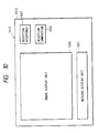
- the display unit 1013 has a body 1019.
- An image display unit 1020 for displaying a moving image, a message display unit 1021 for displaying a message, a first touch sensor 1022 for instructing the acceptance of the reception, and a second touch sensor (disconnecting) means 1023 for instructing the end of the reception are arranged on the front surface of the body 1019, respectively.
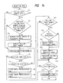
- Fig. 11 is a flowchart showing a control procedure upon reception processing.
- a calling signal is received
- a check is made in step S1 to see if the received calling party number exists or not (in the ISDN used as a line of the multimedia communicating apparatus 1001 of the invention, if the user contracted with the calling party number notification service, when a set-up signal is received from the network, the calling party number is included).
- step S2 a check is made to see if the received calling party number coincides with the registered calling party number which has been registered in the RAM 1006 or not. If YES, step S3 follows and an image of the face which has been registered in the RAM 1006 and corresponds to the received calling party number is displayed in the image display unit 1020 of the display unit 1013.
- the image in the RAM 1006 is the image which was sent from the calling party during the preceding communication and has been stored as a pair together with the calling party number. The user who received the call can immediately recognize who is the calling party by seeing the image displayed in the image display unit 1020.
- step S4 After the image was displayed in the image display unit 1020 in step S3 as mentioned above, in the next step S4, the received calling party number is displayed in the message display unit 1021 in the display unit 1013. In the next step S5, a reception sound is generated from the speaker 1011. Then, step S6 follows. If NO in step S1, that is, if the corresponding calling party number does not exist, step S5 is executed. Further, if NO in step S2, namely, if the received calling party number differs from the registered calling party number which has been registered in the RAM 1006, step S4 is executed. In step S6, a check is made to see if the second touch sensor 1023 for instructing the end of the reception has been depressed or not.
- step S6 if the image displayed in the image display unit 1020 relates to the partner whom the user on the reception side doesn't want to make a speech, the second touch sensor 1023 is depressed. Therefore, if the end of the reception has been instructed by depressing the second touch sensor 1023, the answer in step S6 is YES, so that step S14 is executed and the line is immediately disconnected and the processing routine is finished. That is, the line can be disconnected before responding to the call reception. On the other hand, if the image displayed in the image display unit 1020 relates to the partner whom the user desires to make a speech, the second touch sensor 1023 is not depressed. Therefore, the answer in step S6 is NO and the processing routine advances to step S7.
- step S7 a check is made to see if the first touch sensor 1022 for instructing the acceptance of the reception has been depressed or not. If NO in step S7, step S5 is executed. On the contrary, if YES in step S7, that is, if the acceptance of the reception has been instructed by depressing the first touch sensor 1022, step S8 follows and the audio encode/decode unit 1014 is activated and the transmitted voice is received. Then, step S9 follows and the image encode/decode unit 1015 is activated and the moving image is received. In the next step S10, a check is made to see if the received calling party number exists or not.
- step S11 the first sheet of the received moving image (or an arbitrary one sheet) is registered into the RAM 1006. Then, in step S12, the received calling party number is registered into the RAM 1006 in correspondence to the image which was registered in step S11. After that, step S13 follows. After completion of the registration of the image and the calling party number in steps S12 and S13, the image of the same calling party number is erased. In step S13, a check is made to see if the second touch sensor 1023 for instructing the end of the reception has been depressed or not. If the end of the reception has been instructed by depressing the second touch sensor 1023, step S14 is executed and the line is disconnected. If NO in step S13, step S13 is executed until the end of the reception is instructed. If NO in step S10, namely, if the corresponding calling party number does not exist, step S13 is executed.
- the calling party number has been input from a time point of the received set-up signal.
- the invention is not limited to the above method. It is also possible to use a method whereby the data including the calling party number is multiplexed and transmitted together with the voice and image on the calling party side and the calling party number in the transmitted data is separated and input on the reception side.
- one latest received image has been registered into the RAM 1006 for one calling party number.
- the invention is not limited to the above method but any one of the following methods 1 to 4 can be also used.
- Fig. 12 is a flowchart showing a control procedure upon receiving process in such an embodiment.
- the process in step S3a in Fig. 12 corresponds to a modification of step S3 in Fig. 11.
- Steps S11a, S11b, S11c, S11d, and S11e in Fig. 12 correspond to a modification of step S11 in Fig. 11.
- the other steps in Fig. 12 are similar to those in Fig. 11. That is, in step S3a, a plurality of sheets of images which were registered in correspondence to the calling party numbers are displayed in a lump.
- step S10 If YES in step S10, a counter i is cleared to 0 in step S11a.
- step S11b a check is made to see if the count value of the counter i is equal to N (the maximum value of the number of registered image sheets for one calling party number) or not. If YES, step S12 follows. If NO, step S11c follows. In step S11c, the count value of the counter i is increased one.
- step S11d the ith sheet of image is registered.
- step S11e the apparatus waits for T seconds (preset registration interval between images) and the processing routine is returned to step S11b. Since the other steps in Fig. 12 are similar to those in Fig. 11, the same reference numerals are written on the drawings and their descriptions are omitted.
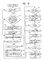
- Fig. 13 is a flowchart showing a control procedure upon receiving process in such an embodiment.
- Step S3b in Fig. 13 corresponds to a modification of step S3 in Fig. 11.
- Steps S21, S22, S23, S24, and S25 in Fig. 13 correspond to a modification of step S11 in Fig. 13.
- the other steps in Fig. 13 are similar to those in Fig. 11. That is, if YES in step S2, the display of the registered images is started in step S3b and the processing routine advances to step S4.
- the single display time of the registered images is set to N seconds and a plurality of registered images are repetitively continuously displayed for this time. Due to this, the images upon call reception can be displayed as a moving image in a manner similar to the ordinary received images.
- a timer is started in step S21.
- the image registration is started in step S22.
- step S23 a check is made to see if N seconds have elapsed from the start of the image registration or not. If NO, step S22 is repeated until N seconds have elapsed. If N seconds have elapsed, the timer is stopped in step S24.
- the image registration is stopped in step S25, then step S12 follows. That is, the images are registered at a predetermined interval of time until N seconds elapse. Since the other steps in Fig. 13 are similar to those in Fig. 11, the same reference numerals are written on the drawings and their descriptions are omitted.
- Fig. 14 is a flowchart showing a control procedure upon receiving process in such an embodiment.
- Step S3c in Fig. 14 corresponds to a modification of step S3 in Fig. 11.
- Steps S31, S32, and S33 in Fig. 14 correspond to a modification of step S11 in Fig. 11.
- the other steps in Fig. 14 are similar to those in Fig. 11. That is, in step S3c, a plurality of sheets of images which were registered for the calling party number are displayed in a lump.
- step S10 a check is made in step S31 to see if the number of images registered for the calling party number has reached N (preset maximum number of sheets) or not. If YES, step S32 follows. If NO, step S33 follows. In step S32, the oldest registered image is deleted (at this time, the number of registered images is equal to N - 1). In step S33, the image which is received at present is additionally registered and step S12 follows. Since the other steps in Fig. 14 are similar to those in Fig. 11, the same reference numerals are written on the drawings and their descriptions are omitted.
- the received images have been registered into the RAM 1006, the invention is not limited to such a method.
- the received images can be also registered to a magnetic disk or a magnetic tape.
- the multimedia communicating apparatus of the second embodiment of the invention comprises: the registering means for registering the received image together with the calling party number upon image reception; display means for displaying the image registered by the registering means corresponding to the calling party number when the same calling party number as the calling party number registered by the registering means was received; and disconnecting means for disconnecting the communication without starting a speech in the case where the image displayed by the display means relates to a partner to whom the user doesn't want to make a speech.
- a plurality of registered images upon reception, a plurality of registered images can be simultaneously displayed or can be displayed as a moving image. Further, a recognition degree of the communication party upon call reception can be raised.
- the received images are registered every plurality of reception times and a plurality of registered images are displayed upon call reception. Consequently, a plurality of persons who use the apparatuses of the same calling party number can be recognized in a lump upon call reception.
Abstract
Description
- The present invention relates to a communicating apparatus which is connected to a network such as an ISDN or the like and executes a communication of a voice, an image, or the like and, more particularly, to a communicating apparatus for displaying a special image upon call reception.
- Hitherto, a television telephone set has been known as a multimedia communicating apparatus which can communicate a voice and an image.
- Hitherto, in the television telephone set connected to the ISDN, when a call reception (reception calling) was performed, an ID number on the calling side (calling party telephone number) is informed to the reception side (CCITT Recommendation, calling number display of I. 251C). Therefore, the number is displayed on an image display apparatus and the telephone number of the calling party can be known.
- However, in the above conventional technique, although the calling party telephone number itself can be known before the reception side responds to a call reception, in order to presume the calling partner from the telephone number, the user actually must learn a number of calling party telephone numbers by heart. Such a notification of the calling party telephone number is not so effective in the case of presuming the calling party before making a response in spite of the notification of the calling party telephone number.
- As a method of solving such a drawback, it is also possible to use a method of knowing the name of the calling party by using a user·user signal (UUS) of the ISDN. As a method whereby information such as a calling party name or the like is informed from the originating call terminal, there has been known a method disclosed in U.S. Patent Application Serial No. 307,506 filed on February 8, 1989.
- However, the above method has a problem such that a condition such that the calling party sends name information is used as a prerequisite and that a special adding apparatus is needed.
- On the other hand, there has been proposed a method whereby a correspondence relation between the telephone number on the originating call side and the calling party name has previously been input on the called side and the calling party name corresponding to the telephone number which coincides with the calling party number which was informed is displayed on an image display apparatus of a television telephone set (U.S. Patent Application Serial No. 363,860 filed on June 9, 1989).
- However, there are problems such that in order to realize the above method, inputting means such as a television camera or the like needs to be newly provided and that it is necessary to previously execute complicated inputting operations.
- It is an object of the invention to solve the drawbacks of the conventional techniques as mentioned above and to provide a communicating apparatus which can register an image regarding a calling party communicating apparatus which is displayed upon call reception by a simple method.
- Another object of the invention is to provide a communicating apparatus which can register an image regarding a calling party communicating apparatus by a simple construction without providing any special inputting apparatus.
- To accomplish the above object, according to the invention, there is provided a communicating apparatus comprising: receiving means for receiving image data which was sent from a calling party communicating apparatus; memory means for storing the image data received by the receiving means in correspondence to ID data indicative of the calling party communicating apparatus; and display means for receiving the ID data upon call reception from the calling party communicating apparatus and for reading out the image data corresponding to the received ID data from the memory means and displaying.
- Another object of the invention is to provide a communicating apparatus with a simple construction in which just before a reception side responds to a reception call, image information regarding a calling party which will be effective if it is displayed on an image display apparatus on the reception side can previously been stored on the reception side by a simple operation.
- Still another object of the invention is to improve information regarding a calling party communicating apparatus which is displayed upon reception.
- That is, according to the invention, a plurality of sheets of information regarding the calling party communicating apparatus are displayed simultaneously or as a moving image upon reception.
- Thus, a recognition degree of the calling party communicating apparatus to the operator can be improved.
- Further another object of the invention is to provide a communicating apparatus which can recognize a plurality of persons which use the apparatus of the same calling party number.
- Further another object of the invention is to provide a communicating apparatus which can see the face of a person as a communication party upon reception.
- Further another object of the invention is to provide a communicating apparatus in which information regarding a communication party is displayed upon reception and when the user doesn't want to communicate by checking the displayed information, a communication can be disconnected before data is received.
- The above and other objects and features of the present invention will become apparent from the following detailed description and the appended claims with reference to the accompanying drawings.
-
- Fig. 1 is a whole arrangement diagram of a television telephone set which is connected to the ISDN according to the first embodiment of the invention;
- Fig. 2 is an external view of the television telephone set connected to the ISDN shown in Fig. 1;
- Fig. 3 is a constructional diagram of a
memory 2 shown in Fig. 1; - Figs. 4 and 6 are program flowcharts showing fetching (storing) control procedure of image information which are executed in a
control unit 1 shown in Fig. 1; - Fig. 5 is a program flowchart showing a display control procedure of image information which is executed in the
control unit 1 shown in Fig. 1; - Fig. 7 is an external view of another embodiment of the television telephone set connected to the ISDN shown in Fig. 2;
- Fig. 8 is a program flowchart showing a fetching (storing) control procedure of image information which is executed in the control unit of the television telephone set shown in Fig. 7;
- Fig. 9 is a block arrangement diagram of a multimedia communicating apparatus according to the second embodiment of the invention;
- Fig. 10 is a front view of a display unit of the apparatus shown in Fig. 9;
- Fig. 11 is a flowchart showing a control procedure of the apparatus; and
- Figs. 12, 13, and 14 are flowcharts in the case of modifying a part of the flowchart of Fig. 11.
- Embodiments of the invention will be described in detail hereinbelow with reference to the drawings.
- Fig. 1 is a whole arrangement diagram of a television telephone set which is connected to the ISDN according to the first embodiment of the invention. In the diagram,
reference numeral 1 denotes a control unit comprising a CPU for controlling the operation of the ISDN connected television telephone set, a ROM, and a RAM. Amemory 2 is connected to thecontrol unit 1. The following various apparatuses are connected to thecontrol unit 1 through an I/O port (not shown). That is, to the I/O port, there are connected: anoperation key 3 for designating and inputting a calling party telephone number or the like upon calling or the like from this side of the television telephone; animage display unit 4 comprising a CRT display for displaying image information which is sent from the calling party and the telephone number or the like of the calling party; ahandset 5 as a transceiver for transferring a voice; acamera unit 6 for inputting an image on this side; anaudio codec 7 for executing the A/D and D/A conversions between a digital signal which is processed by the ISDN and an audio analog signal which is input/output to/from thehandset 5; animage codec 8 for executing the D/A conversion from the digital signal of the ISDN into the image analog signal of thedisplay unit 4 and the A/D conversion from the image analog signal of thecamera unit 6 into the digital signal of the ISDN; and anISDN interface 9 for connecting an ISDN (integrated services digital network) 10 and the television telephone, respectively. Further, animage fetch key 11 comprising a push switch is connected to the I/O port. Theimage fetch key 11 generates a command signal to store a calling side image such as a face of the person on the calling party side or the like into thememory 2 by a pushing operation. - Fig. 2 shows an external view of the television telephone set connected to the ISDN constructed as mentioned above.
- Fig. 3 shows a part of a construction in the
memory 2. Thememory 2 is constructed by a volatile memory device comprising fourareas 201 to 204.Reference numeral 201 denotes the calling party number area in call reception for storing the calling party telephone number (destination side telephone number) which is sent from the ISDN upon call reception (calling on the reception side) and 202 indicates the calling party number area in line connection for storing the calling party number when the line is connected, that is, while a speech is being executed. Upon reception by calling from the calling party, the calling party number which is sent from the ISDN is stored into thearea 202. Upon calling from this side, the calling party number which was input by using theoperation key 3 is stored into thearea 202.Reference numeral 203 represents n telephone number areas of Nos. 1 to n each for storing the telephone number.Reference numeral 204 indicates n image areas of Nos. 1 to n each for storing image information in correspondence to the areas in thearea 203. - A procedure for a fetching (storing) control of image information which is executed by the
control unit 1 will now be described in detail in accordance with a program flowchart shown in Fig. 4. This program is executed when theimage fetch key 11 was pushed (depressed) when the line is connected, that is, while an image from the calling party is being received. - In the first step S401, the calling party number stored in the calling
party number area 202 in line connection, that is, the calling party number which is sent from the ISDN in the case of the call reception by calling from the calling party side or the calling party number which was input by theoperation key 3 in the case of the calling from this side is read out. The calling party number in line connection is stored into thearea 202 upon reception or key inputting operation. - A pointer to designate an object to be compared is set into the top telephone number area of No. 1 in the area 203 (step S402). A check is made to see if the number information stored in the telephone number area of No. 1 coincides with the calling party number which was read out in step S401 or not (step S403). If NO in step S403, the pointer is sequentially moved to the next telephone number area (the telephone number area of No. 2 in this case) (step S404). In step S405, a check is made to see if the comparison between the calling party number which had been read out in step S401 and all of the telephone numbers stored in the whole areas in which the telephone numbers had been stored in the
telephone number area 203 has been completed or not. That is, a check is made to see if the pointer has been moved to all of the telephone number areas in which the telephone numbers had been stored and the point has arrived at the telephone number area in which no telephone number is stored or if there is no area to which the pointer moves (the pointer has already reached the last telephone number area of No. n) or not as a result of the movement of the pointer. If NO in step S405, that is, if the comparison between the calling party number (i.e., destination side number) which was read out in step S401 and all of the telephone numbers in the whole areas in which the telephone numbers have been stored in thetelephone number area 203 is not completed yet, the processing routine is returned to step S403. The processes in steps S403 to S405 are repeated. - When the calling party number which was read out in step S401 coincides with the telephone number stored in any one of the areas of Nos. 1 to n in the telephone number area 203 (if YES in step S403), the image which had been received from the calling party through the ISDN and was displayed in the
image display unit 4 is stored (step S406) into the image area corresponding to the telephone number area in which the coincident telephone number has been stored. The present program is finished. The execution of step S406 intends to change the image which has already been stored. - If YES in step S405, that is, if the number corresponding to the calling party number which was read out in step S401 cannot be found out from all of the areas in the
telephone number area 203, a check is made to see if a vacant area in which no telephone number is stored exists in thetelephone number area 203 or not (step S407). If YES in step S407, the calling party number which was read out in step S401 is stored into the top area in the vacant area and the image information which was received from the calling party and displayed in theimage display unit 4 is stored into the image area corresponding to the relevant area into which the calling party number was stored (step S408). The present program is finished. On the other hand, if NO in step S407, the storage contents of a predetermined set of areas in thetelephone number area 203 are erased and the calling party number which was read out in step S401 and the image information displayed in thedisplay unit 4 are respectively stored (updated) (step S409). The predetermined set of areas can be also changed in accordance with the order of the area numbers (1, 2, ..., n) every completion of the storing and updating processes. - As mentioned above, by merely pushing the image fetch key 11 in the line connection, the image of the face of the person on the calling party side upon speech communication can be easily stored in correspondence to the calling party telephone number irrespective of the reception and transmission. That is, the calling party telephone number and the image information which is peculiar to the calling party are stored in correspondence to each set of the
telephone number area 203 and theimage area 204 corresponding thereto. - A procedure of the display control of image information which is executed by the
control section 1 and is used to access the image information stored as mentioned above upon reception call and to display by theimage display unit 4 will now be described in detail in accordance with a program flowchart shown in Fig. 5. This program is executed every reception call (calling on the reception side). - In the first step S501, the calling party number (i.e., destination number) stored in the calling
party number area 201 in call reception, that is, the calling party number which is sent from the ISDN is read out. The calling party number is stored in thearea 201. - Then, the pointer to designate an object to be compared is set into the top telephone number area of No. 1 in the telephone number area 203 (step S502). A check is made to see if the calling party number stored in the telephone number area of No. 1 coincides with the calling party number which was read out in step S501 or not (step S503). If NO in step S503, the pointer is sequentially moved to the next telephone number area (the telephone number area of No. 2 in this case) (step S504). In step S505, a check is made to see if the comparison between the calling party number which had been read out in step S501 and all of the telephone numbers in the whole areas in which the telephone numbers had been stored in the
telephone number area 203 has been completed or not. That is, a check is made to see if the pointer has been moved to all of the telephone number areas in which the telephone numbers had been stored and the pointer has reached the telephone number area in which no telephone number is stored or there is no area to which the pointer moves (the pointer has already reached the last telephone number area of No. n) or not as a result of the movement of the pointer in step S504. If NO in step S505, that is, if the comparison between the calling party number which was read out in step S501 and all of the telephone numbers in the whole areas in which the telephone numbers have been stored in thetelephone number area 203 is not completed yet, the processing routine is returned to step S503 and the processes in steps S503 to S505 are repeated. - If the calling party number which was read out in step S501 coincides with the telephone number stored in any one of the areas in the telephone number area 203 (namely, if YES in step S503), the image information stored in the image area corresponding to the telephone number area in which the coincident telephone number has been stored is displayed in the display unit 4 (step S506) and the processing routine advances to step S507, which will be explained hereinlater.
- If YES in step S505, that is, if the number corresponding to the calling party number which was read out in step S501 cannot be found out from all of the areas in the
telephone number area 203, only the calling party number which was informed from the ISDN is displayed in the display unit 4 (step S507). A reception sound to inform the call reception is generated (step S508) and the present program is finished. - If step S507 was executed after the image information had been displayed in step S506, both of the image information and the calling party number are displayed by the
display unit 4. - As mentioned above, not only the calling party number is displayed in the
image display unit 4 upon call reception but also the image information which is peculiar to the calling party, for instance, the image of the face or the like of the person on the calling party side is displayed in theimage display unit 4. Thus, the calling partner can be easily presumed before response and the user can prepare for a response. - In the above embodiment, the calling
party number area 201 upon call reception and the callingparty number area 202 in line connection have separately been provided in thememory 2. However, the invention is not necessarily limited to such a construction. The functions of both of those areas can be also performed by a single area. - On the other hand, it is not always necessary to provide an image fetch key 3 but, for instance, it is also possible to execute the program of Fig. 4 when a * key and a 0 key in the
operation key 4 were simultaneously depressed. Or, it is also possible to provide a touch sensor for theimage display unit 4 and to execute the program of Fig. 4 by touching theimage display unit 4. - Further, it is also possible to construct in a manner such that a touch panel is attached to the
image display unit 4 and by touching a predetermined position of an image which is displayed in theimage display unit 4, an inputting operation to thecontrol unit 1 is executed, and the image fetch key 3 also has the function of theoperation key 4. - Further, the process in step S409 in Fig. 4 in the embodiment can be also executed in the following manner. That is, the frequency of the reading and displaying operations due to the call reception of the image information of the corresponding image area is counted every area in the
telephone number area 203 in thememory 2 and the area having the minimum frequency is used to store and update the calling party number and the image information corresponding to a command output from the image fetch key 11. That is, when the storage area of the image lacks, the storage image of a small frequency which is read out in response to the call reception is erased together with the corresponding telephone number, thereby updating to the new telephone number and image information. Fig. 6 shows a flowchart in this case. - In the above embodiment, the image which is sent from the calling party has been used as image information. However, the image photographed by the
camera unit 6 on this side can be also input as image information to theimage area 204. In this case, since thecamera unit 6 for transmitting the image is also commonly used, there is no need to additionally provide another inputting means. For instance, a memorandum on which information such as process of a business talk with the calling party, thanks to a present from the calling party, name and family construction of the calling party, and the like was written is put up in front of thecamera unit 6 as shown in Fig. 7 and the image fetch key 11 is depressed, thereby storing the image on the memorandum into theimage area 204, and the calling party telephone number is stored into the corresponding area in thetelephone number area 203 by theoperation key 3. - That is, when the television telephone executes none of the transmission and reception, by putting up the memorandum sheet to a position in front of the
camera unit 6 and depressing the image fetch key 11, a program of a flowchart shown in Fig. 8 is executed. It is first instructed to input the calling party telephone number by theoperation key 3. When the calling party telephone number is input, the image on the memorandum sheet is read as image information by thecamera unit 6. After that, the calling party telephone number and the image information are stored into thememory 2 in accordance with the same procedure as that of the processes in step S402 and subsequent steps in Fig. 4. On the other hand, the display upon call reception is executed in accordance with the same procedure as that shown in Fig. 5. - As described in detail above, according to the first embodiment, in the television telephone set connected to the ISDN having the calling party number display service, the communicating apparatus comprises: the first memory for storing a calling party number from the ISDN upon call reception and for storing the calling party number (i.e., destination side number) in line connection; the second memory having a plurality of sets of telephone number areas and image areas respectively corresponding to the telephone number areas; the image fetching means for outputting a command to store image information which is displayed on the image display apparatus of the television telephone set into the second memory; and the control means for controlling in a manner such that the calling party number (destination side number) stored in the first memory and the image information displayed on the image display apparatus are respectively stored into either one of the plurality of sets of telephone number areas and image areas in the second memory in accordance with a command output from the image fetching means in the line connection and the calling party number stored in the first memory and the calling party numbers (destination side numbers) stored in the telephone number areas in the second memory are sequentially compared upon call reception from the ISDN and when they coincide, the image information stored in the image area in the second memory corresponding to the telephone number area in which the coincident calling party number (destination side number) has been stored is displayed on the image display apparatus. Therefore, in spite of a simple apparatus, the image information enough to presume the calling party can be previously stored on the reception side together with the corresponding telephone number by the simple operation. Therefore, just before the reception side responds to the call reception, the image information regarding the calling party, for instance, the face of the calling party or the like is displayed on the image display apparatus on the reception side and the calling party can be easily presumed.
- As a second embodiment, explanation will now be made with respect to the case where the image corresponding to the calling party number (i.e., destination side number) upon call reception is displayed and the user can immediately disconnect the communication if he doesn't talk to the calling party and the case where a moving image is used as an image.
- The second embodiment of the invention will now be described hereinbelow with reference to the drawings. Fig. 9 is a block arrangement diagram of a multimedia communicating apparatus which can communicate a voice, data, and a moving image according to an embodiment of the invention. In the diagram,
reference numeral 1001 denotes a multimedia communicating apparatus using a line based on the ISDN (integrated services digital network). Themultimedia communicating apparatus 1001 has amain control unit 1002. Themain control unit 1002 comprises: anoperation unit 1003; aCPU 1004; aROM 1005; and a RAM (registering means) 1006. Theoperation unit 1003 executes various operations of the wholemultimedia communicating apparatus 1001 and has a keyboard (not shown) and a touch sensor on adisplay unit 1013, which will be explained hereinlater. TheCPU 1004 controls thewhole apparatus 1001. A program to control themultimedia communicating apparatus 1001 which is executed by theCPU 1004 has been stored in theROM 1005. Various data, images, calling party numbers, and the like have been stored in theRAM 1006. - An
audio interface unit 1007 and avideo interface unit 1007 are respectively connected to themain control unit 1002. A handset (transceiver) 1009 for inputting or outputting a voice, amicrophone 1010 for inputting a voice, and aspeaker 1011 for generating the voice are connected to theaudio interface unit 1007, respectively. Theaudio interface unit 1007 executes the interface with thehandset 1009,microphone 1010, andspeaker 1011. Acamera 1012 for inputting a moving image and the display unit (display means) 1013 for outputting the moving image or a message are connected to thevideo interface unit 1008. Thevideo interface unit 1008 executes the interface with thecamera 1012 anddisplay unit 1013. Theaudio interface unit 1007 is connected to an audio encode/decode unit 1014 for compressing or expanding an audio signal. On the other hand, thevideo interface unit 1008 is connected to an image encode/decode unit 1015 for compressing or expanding an image signal. The encoding/decoding process of a moving image has been disclosed in detail in the CCITT recommendation idea H.261. The audio encode/decode unit 1014 and the image encode/decode unit 1015 are connected to a multiplication/separation unit 1016 for multiplexing and separating the data, voice, and image signal. The multiplication/separation unit 1016 has been disclosed in detail in the CCITT recommendation idea H.221. Adata interface unit 1017 for performing the interface with theCPU 1004 is connected between the multiplication/separation unit 1016 and themain control unit 1002. The multiplication/separation unit 1016 is connected to aline interface unit 1018 for executing the interface with the line (ISDN). - As shown in Fig. 10, the
display unit 1013 has abody 1019. Animage display unit 1020 for displaying a moving image, amessage display unit 1021 for displaying a message, afirst touch sensor 1022 for instructing the acceptance of the reception, and a second touch sensor (disconnecting) means 1023 for instructing the end of the reception are arranged on the front surface of thebody 1019, respectively. - A control procedure of the
multimedia communicating apparatus 1001 will now be described with reference to Fig. 11. Fig. 11 is a flowchart showing a control procedure upon reception processing. First, when a calling signal is received, a check is made in step S1 to see if the received calling party number exists or not (in the ISDN used as a line of themultimedia communicating apparatus 1001 of the invention, if the user contracted with the calling party number notification service, when a set-up signal is received from the network, the calling party number is included). - If the calling party number exists, the answer in step S1 is YES and the processing routine advances to step S2. In step S2, a check is made to see if the received calling party number coincides with the registered calling party number which has been registered in the
RAM 1006 or not. If YES, step S3 follows and an image of the face which has been registered in theRAM 1006 and corresponds to the received calling party number is displayed in theimage display unit 1020 of thedisplay unit 1013. The image in theRAM 1006 is the image which was sent from the calling party during the preceding communication and has been stored as a pair together with the calling party number. The user who received the call can immediately recognize who is the calling party by seeing the image displayed in theimage display unit 1020. After the image was displayed in theimage display unit 1020 in step S3 as mentioned above, in the next step S4, the received calling party number is displayed in themessage display unit 1021 in thedisplay unit 1013. In the next step S5, a reception sound is generated from thespeaker 1011. Then, step S6 follows. If NO in step S1, that is, if the corresponding calling party number does not exist, step S5 is executed. Further, if NO in step S2, namely, if the received calling party number differs from the registered calling party number which has been registered in theRAM 1006, step S4 is executed. In step S6, a check is made to see if thesecond touch sensor 1023 for instructing the end of the reception has been depressed or not. That is, if the image displayed in theimage display unit 1020 relates to the partner whom the user on the reception side doesn't want to make a speech, thesecond touch sensor 1023 is depressed. Therefore, if the end of the reception has been instructed by depressing thesecond touch sensor 1023, the answer in step S6 is YES, so that step S14 is executed and the line is immediately disconnected and the processing routine is finished. That is, the line can be disconnected before responding to the call reception. On the other hand, if the image displayed in theimage display unit 1020 relates to the partner whom the user desires to make a speech, thesecond touch sensor 1023 is not depressed. Therefore, the answer in step S6 is NO and the processing routine advances to step S7. In step S7, a check is made to see if thefirst touch sensor 1022 for instructing the acceptance of the reception has been depressed or not. If NO in step S7, step S5 is executed. On the contrary, if YES in step S7, that is, if the acceptance of the reception has been instructed by depressing thefirst touch sensor 1022, step S8 follows and the audio encode/decode unit 1014 is activated and the transmitted voice is received. Then, step S9 follows and the image encode/decode unit 1015 is activated and the moving image is received. In the next step S10, a check is made to see if the received calling party number exists or not. If YES, in the next step S11, the first sheet of the received moving image (or an arbitrary one sheet) is registered into theRAM 1006. Then, in step S12, the received calling party number is registered into theRAM 1006 in correspondence to the image which was registered in step S11. After that, step S13 follows. After completion of the registration of the image and the calling party number in steps S12 and S13, the image of the same calling party number is erased. In step S13, a check is made to see if thesecond touch sensor 1023 for instructing the end of the reception has been depressed or not. If the end of the reception has been instructed by depressing thesecond touch sensor 1023, step S14 is executed and the line is disconnected. If NO in step S13, step S13 is executed until the end of the reception is instructed. If NO in step S10, namely, if the corresponding calling party number does not exist, step S13 is executed. - In the embodiment, the calling party number has been input from a time point of the received set-up signal. However, the invention is not limited to the above method. It is also possible to use a method whereby the data including the calling party number is multiplexed and transmitted together with the voice and image on the calling party side and the calling party number in the transmitted data is separated and input on the reception side.
- On the other hand, in the above embodiment, one latest received image has been registered into the
RAM 1006 for one calling party number. However, the invention is not limited to the above method but any one of the followingmethods ① to ④ can be also used. - ① The oldest received image is registered for one calling party number and the image registering process is not executed for the same calling party number.
- ② A plurality of sheets of received images are registered in a lump for one calling party number and a plurality of sheets of registered images are displayed in the
image display unit 1020 upon call reception. Fig. 12 is a flowchart showing a control procedure upon receiving process in such an embodiment. The process in step S3a in Fig. 12 corresponds to a modification of step S3 in Fig. 11. Steps S11a, S11b, S11c, S11d, and S11e in Fig. 12 correspond to a modification of step S11 in Fig. 11. Further, the other steps in Fig. 12 are similar to those in Fig. 11. That is, in step S3a, a plurality of sheets of images which were registered in correspondence to the calling party numbers are displayed in a lump. If YES in step S10, a counter i is cleared to 0 in step S11a. In the next step S11b, a check is made to see if the count value of the counter i is equal to N (the maximum value of the number of registered image sheets for one calling party number) or not. If YES, step S12 follows. If NO, step S11c follows. In step S11c, the count value of the counter i is increased one. In step S11d, the ith sheet of image is registered. In step S11e, the apparatus waits for T seconds (preset registration interval between images) and the processing routine is returned to step S11b. Since the other steps in Fig. 12 are similar to those in Fig. 11, the same reference numerals are written on the drawings and their descriptions are omitted. - ③ Continuous received images are registered for a predetermined time for one calling party number and the continuous registered images are repetitively displayed as a moving image by the
image display unit 1020 upon call reception. Fig. 13 is a flowchart showing a control procedure upon receiving process in such an embodiment. Step S3b in Fig. 13 corresponds to a modification of step S3 in Fig. 11. Steps S21, S22, S23, S24, and S25 in Fig. 13 correspond to a modification of step S11 in Fig. 13. Further, the other steps in Fig. 13 are similar to those in Fig. 11. That is, if YES in step S2, the display of the registered images is started in step S3b and the processing routine advances to step S4. The single display time of the registered images is set to N seconds and a plurality of registered images are repetitively continuously displayed for this time. Due to this, the images upon call reception can be displayed as a moving image in a manner similar to the ordinary received images. On the other hand, if YES in step S10, a timer is started in step S21. The image registration is started in step S22. In step S23, a check is made to see if N seconds have elapsed from the start of the image registration or not. If NO, step S22 is repeated until N seconds have elapsed. If N seconds have elapsed, the timer is stopped in step S24. The image registration is stopped in step S25, then step S12 follows. That is, the images are registered at a predetermined interval of time until N seconds elapse. Since the other steps in Fig. 13 are similar to those in Fig. 11, the same reference numerals are written on the drawings and their descriptions are omitted. - ④ Each time of the reception, the received image is additionally registered for one calling party number and a plurality of sheets of registered images are displayed in the
image display unit 1020 upon call reception. Fig. 14 is a flowchart showing a control procedure upon receiving process in such an embodiment. Step S3c in Fig. 14 corresponds to a modification of step S3 in Fig. 11. Steps S31, S32, and S33 in Fig. 14 correspond to a modification of step S11 in Fig. 11. Further, the other steps in Fig. 14 are similar to those in Fig. 11. That is, in step S3c, a plurality of sheets of images which were registered for the calling party number are displayed in a lump. On the other hand, if YES in step S10, a check is made in step S31 to see if the number of images registered for the calling party number has reached N (preset maximum number of sheets) or not. If YES, step S32 follows. If NO, step S33 follows. In step S32, the oldest registered image is deleted (at this time, the number of registered images is equal to N - 1). In step S33, the image which is received at present is additionally registered and step S12 follows. Since the other steps in Fig. 14 are similar to those in Fig. 11, the same reference numerals are written on the drawings and their descriptions are omitted. - Further, in the embodiment, although the received images have been registered into the
RAM 1006, the invention is not limited to such a method. The received images can be also registered to a magnetic disk or a magnetic tape. - As mentioned above, the multimedia communicating apparatus of the second embodiment of the invention comprises: the registering means for registering the received image together with the calling party number upon image reception; display means for displaying the image registered by the registering means corresponding to the calling party number when the same calling party number as the calling party number registered by the registering means was received; and disconnecting means for disconnecting the communication without starting a speech in the case where the image displayed by the display means relates to a partner to whom the user doesn't want to make a speech.
- Therefore, upon reception, by seeing the image of the face of the partner displayed by the display means, it is possible to immediately recognize who is the partner without starting the speech. Therefore, the communication can be soon disconnected for the partner to whom the user doesn't want to make a speech.
- On the other hand, according to the embodiment, upon reception, a plurality of registered images can be simultaneously displayed or can be displayed as a moving image. Further, a recognition degree of the communication party upon call reception can be raised. Although there is also a case where a plurality of persons use the apparatuses of the same calling party number, according to the embodiment shown in Fig. 14, the received images are registered every plurality of reception times and a plurality of registered images are displayed upon call reception. Consequently, a plurality of persons who use the apparatuses of the same calling party number can be recognized in a lump upon call reception.
- Although the invention has been described above with respect to the preferred embodiments, the invention is not limited to the foregoing embodiments. Many modifications and variations are possible within the spirit and scope of the appended claims of the invention.
Claims (18)
- A communicating apparatus comprising:
receiving means for receiving image data sent from a calling party communicating apparatus;
memory means for storing the image data received by the receiving means in correspondence to ID data indicative of the calling party communicating apparatus; and
display means for receiving the ID data upon reception from the calling party communicating apparatus and for reading out the image data corresponding to the received ID data from the memory means and for displaying. - An apparatus according to claim 1, further having means for selecting the storing operation of the image data into the memory means, and wherein when the storing operation is selected by the selecting means, the memory means stores the image data which is being received.
- An apparatus according to claim 2, wherein the memory means stores a plurality of image data from a plurality of communicating apparatuses in correspondence to a plurality of ID data.
- An apparatus according to claim 3, wherein when the storing operation is selected by the selecting means, if storage areas in the memory means are filled with data, the ID data and the image data in a predetermined storage area are erased and the ID data of the calling party communicating apparatus during communication and the image data from the calling party communicating apparatus are newly stored into said predetermined storage area.
- An apparatus according to claim 4, wherein the predetermined area from which the ID data and the image data are erased is an area in which the image data from the communicating apparatus having a small reception frequency has been stored.
- An apparatus according to claim 1, wherein if the image data corresponding to the ID data indicative of the calling party communicating apparatus has already been stored in the memory means, the stored image data is updated to the newly received image data.
- An apparatus according to claim 1, further having disconnecting means for disconnecting the communication before reception of the image data from the calling party communicating apparatus.
- A communicating apparatus comprising:
registering means for registering a received image together with a calling party number upon reception of the image;
display means for displaying the image registered by the registering means and corresponding to the calling party number when the same calling party number as the calling party number registered by the registering means was received;
disconnecting means for disconnecting a communication without starting a speech in the case where the image displayed by the display means relates to a calling party to whom the speech is not desired. - A communicating apparatus comprising:
receiving means for receiving a plurality of sheets of images sent from a calling party communicating apparatus;
memory means for storing the plurality of sheets of images received by the receiving means in correspondence to ID data indicative of the calling party communicating apparatus; and
display means for displaying the plurality of sheets of images stored in the memory means upon call reception from the calling party communicating apparatus. - An apparatus according to claim 9, wherein the display means simultaneously displays a plurality of sheets of images.
- An apparatus according to claim 9, wherein the display means sequentially displays a plurality of sheets of images and displays and outputs as a moving image.
- A communicating apparatus comprising:
audio data input/output means;
image data input/output means;
communicating means for transmitting and receiving the audio data and the image data;
memory means for receiving an image from the image data input means and for storing in correspondence to ID data indicative of a calling party communicating apparatus; and
display means for displaying the image stored in the memory means upon call reception from the calling party communicating apparatus. - A television telephone connected to an ISDN having a calling party number display service, comprising:
a first memory for storing a calling party number from the ISDN upon call reception;
a second memory having telephone number areas and image areas corresponding to the telephone number areas;
image fetching means for outputting a command to store image information which is displayed by an image display apparatus of the television telephone into the second memory;
means for respectively storing the calling party number stored in the first memory and the image information displayed by the image display apparatus into the telephone number area and the image area in the second memory in accordance with a command output from the image fetching means during connection of a line;
means for comparing the calling party number stored in the first memory and the calling party numbers stored in the telephone number areas in the second memory upon call reception from the ISDN; and
control means for controlling in a manner such that when those calling party numbers coincide, the image information stored in the image area in the second memory corresponding to the telephone number area in which the coincident calling party number has been stored is displayed by the image display apparatus. - A telephone according to claim 13, wherein the first memory stores the calling party number from the ISDN in the case of a calling from the calling party side during connection of the line and stores the calling party number which was called in the case of a calling from this side.
- A telephone according to claim 13, wherein the first memory comprising a calling party number area in call reception and a calling party number area in line connection.
- A telephone according to claim 13, wherein the image fetching means generates an output signal by touching the image display apparatus.
- A telephone according to claim 13, wherein the control means controls in a manner such that a frequency when reading out and displaying the image information stored in the corresponding image area is counted every telephone number area in the second memory and the telephone number area having the smallest frequency is used to store and update the calling party number and the image information corresponding to a command output from the image fetching means.
- A videophone which can display an image in response to identity data relating to the originator of an incoming call, the image being derived from image data which has been pre-stored in association with the identity data, the videophone comprising pre-storing means for pre-storing such image data,
characterised in that the pre-storing means is operable to store as said image data at least one of (a) image data received from the other party during a videophone call, and (b) image data provided by an image sensing means of the videophone which image sensing means is used during a videophone call to generate image data to be provided to the other party.
Applications Claiming Priority (4)
| Application Number | Priority Date | Filing Date | Title |
|---|---|---|---|
| JP332424/89 | 1989-12-20 | ||
| JP33242489A JPH03191648A (en) | 1989-12-20 | 1989-12-20 | Isdn connection video telephone set |
| JP25341590A JPH04132358A (en) | 1990-09-21 | 1990-09-21 | Multi-media communication equipment |
| JP253415/90 | 1990-09-21 |
Publications (3)
| Publication Number | Publication Date |
|---|---|
| EP0436345A2 true EP0436345A2 (en) | 1991-07-10 |
| EP0436345A3 EP0436345A3 (en) | 1991-12-18 |
| EP0436345B1 EP0436345B1 (en) | 1999-05-26 |
Family
ID=26541186
Family Applications (1)
| Application Number | Title | Priority Date | Filing Date |
|---|---|---|---|
| EP90313817A Expired - Lifetime EP0436345B1 (en) | 1989-12-20 | 1990-12-18 | Voice and image communicating apparatus |
Country Status (3)
| Country | Link |
|---|---|
| US (1) | US5305097A (en) |
| EP (1) | EP0436345B1 (en) |
| DE (1) | DE69033126T2 (en) |
Cited By (29)
| Publication number | Priority date | Publication date | Assignee | Title |
|---|---|---|---|---|
| EP0524623A2 (en) * | 1991-07-24 | 1993-01-27 | Hitachi, Ltd. | Video telephone |
| US5349638A (en) * | 1993-01-25 | 1994-09-20 | Micro-Technology Inc.-Wisconsin | Universal calling/originating number identification |
| EP0641141A2 (en) * | 1993-08-30 | 1995-03-01 | AT&T Corp. | Method for sending and receiving video images |
| US5414457A (en) * | 1990-12-26 | 1995-05-09 | Canon Kabushiki Kaisha | Multi-media communication apparatus |
| US5418560A (en) * | 1991-05-21 | 1995-05-23 | Canon Kabushiki Kaisha | Voice and image data communication apparatus |
| US5510829A (en) * | 1990-03-15 | 1996-04-23 | Canon Kabushiki Kaisha | Voice and video communication apparatus |
| US5541639A (en) * | 1992-10-23 | 1996-07-30 | Hitachi, Ltd. | Video conference system automatically started at reserved time |
| US5587735A (en) * | 1991-07-24 | 1996-12-24 | Hitachi, Ltd. | Video telephone |
| WO1997017793A1 (en) * | 1995-11-06 | 1997-05-15 | Philips Electronics N.V. | Television receiver with caller-id feature |
| EP0773686A3 (en) * | 1991-07-15 | 1997-08-13 | Hitachi Ltd | Equipment for a teleconference |
| EP0778704A3 (en) * | 1991-07-15 | 1997-08-20 | Hitachi Ltd | Teleconference module |
| GB2319136A (en) * | 1993-10-01 | 1998-05-13 | Vicor Inc | Teleconference type facility having a "call waiting" type facility |
| EP0899952A2 (en) * | 1993-10-01 | 1999-03-03 | Vicor, Inc. | Call detection and handling in multimedia collaboration system |
| EP0901263A2 (en) * | 1997-09-04 | 1999-03-10 | Nokia Mobile Phones Ltd. | Method for handling phone numbers in mobile station and mobile station |
| WO1999025107A2 (en) * | 1997-11-06 | 1999-05-20 | Telia Ab (Publ) | Call setup in mobile systems |
| US5966164A (en) * | 1991-02-10 | 1999-10-12 | Hitachi, Ltd. | Television telephone |
| US5970054A (en) * | 1991-07-15 | 1999-10-19 | Hitachi, Ltd. | Multipoint teleconference system employing H. 221 frames |
| EP0973309A2 (en) * | 1998-07-17 | 2000-01-19 | Siemens Information and Communication Networks Inc. | System and method for enhanced caller name alerting |
| DE19914553A1 (en) * | 1999-03-31 | 2000-10-05 | Helmuth Eberst | Multifunction display device for telephone |
| EP1067748A2 (en) * | 1999-07-06 | 2001-01-10 | Matsushita Electric Industrial Co., Ltd. | Fernsprechgerät |
| WO2001003406A1 (en) * | 1999-06-30 | 2001-01-11 | Nokia Corporation | Method and system for providing a caller picture |
| WO2001078358A2 (en) * | 2000-04-10 | 2001-10-18 | Nortel Networks Ltd. | Providing announcement information in requests to establish call sessions in a data network |
| GB2372402A (en) * | 2000-11-17 | 2002-08-21 | Nec Corp | Generating a telephone directory with picture data |
| WO2003039176A1 (en) * | 2001-10-30 | 2003-05-08 | Nokia Corporation | Transfer of personalisation items between communication terminals |
| EP1376993A3 (en) * | 2002-06-28 | 2004-04-14 | Rohm Co., Ltd. | Portable communicating apparatus |
| US7130394B2 (en) * | 2003-04-18 | 2006-10-31 | Casio Computer Co., Ltd. | Imaging apparatus with communication function, image data storing method and computer program |
| EP1865694A1 (en) * | 2006-06-07 | 2007-12-12 | Sony Ericsson Mobile Communications Japan, Inc. | Information processing device, information processing method, information processing program and portable terminal device |
| US8160221B2 (en) | 1994-01-05 | 2012-04-17 | Henderson Daniel A | Cellular telephone with the ability to display and store picture and video messages and caller ID received from a message originator |
| CN109068085A (en) * | 2018-09-12 | 2018-12-21 | 北京小米移动软件有限公司 | Call handling method and device |
Families Citing this family (12)
| Publication number | Priority date | Publication date | Assignee | Title |
|---|---|---|---|---|
| US6594688B2 (en) | 1993-10-01 | 2003-07-15 | Collaboration Properties, Inc. | Dedicated echo canceler for a workstation |
| US6191807B1 (en) | 1994-05-27 | 2001-02-20 | Canon Kabushiki Kaisha | Communication apparatus and method for performing a file transfer operation |
| AU4590196A (en) * | 1994-12-14 | 1996-07-03 | Multimedia Systems Corporation | Interactive multimedia device including caller identification decoding feature |
| USH1714H (en) * | 1995-05-03 | 1998-03-03 | Lucent Technologies Inc. | Automatic still image transmission upon call connection |
| KR0168802B1 (en) * | 1996-03-30 | 1999-02-01 | 김광호 | Isdn exchanger's automatic response function |
| NO974863A (en) * | 1997-10-02 | 1998-09-28 | Comuniq Asa | Procedure for recording and storing received audio signals and any image signals in connection with a telephone set |
| USD425053S (en) * | 1999-01-04 | 2000-05-16 | Lucent Technologies Inc. | Housing for a display telephone unit |
| GB0011747D0 (en) * | 2000-05-17 | 2000-07-05 | Butterworth Martyn | Improvements related to telecoms |
| JP2004187273A (en) * | 2002-11-22 | 2004-07-02 | Casio Comput Co Ltd | Portable telephone terminal, and calling history display method |
| US20050201470A1 (en) * | 2004-03-12 | 2005-09-15 | John Sievers | Intra block walk around refresh for H.264 |
| USD769839S1 (en) * | 2015-02-25 | 2016-10-25 | Panasonic Intellectual Property Management Co., Ltd. | Telephone base unit with camera |
| CN110313166A (en) * | 2017-02-21 | 2019-10-08 | 萨罗尼科斯贸易与服务一人有限公司 | For reminding method, system, electronic equipment, the communication server and the device of urgent call to callee |
Citations (5)
| Publication number | Priority date | Publication date | Assignee | Title |
|---|---|---|---|---|
| DE3816428A1 (en) * | 1987-05-13 | 1988-12-08 | Ricoh Kk | IMAGE TRANSFER SYSTEM |
| JPS63316966A (en) * | 1987-06-19 | 1988-12-26 | Fujitsu Ltd | Telephone directory registering system |
| EP0320828A2 (en) * | 1987-12-17 | 1989-06-21 | Mitsubishi Denki Kabushiki Kaisha | Methods for transmitting and displaying a still picture image in a still picture video telephone apparatus |
| JPH01212056A (en) * | 1988-02-18 | 1989-08-25 | Toshiba Corp | Video telephone equipment |
| JPH01220938A (en) * | 1988-02-29 | 1989-09-04 | Nec Eng Ltd | Television telephone set |
Family Cites Families (8)
| Publication number | Priority date | Publication date | Assignee | Title |
|---|---|---|---|---|
| JPS60105348A (en) * | 1983-11-14 | 1985-06-10 | Kyocera Corp | Multi-function key input device |
| EP0153903B1 (en) * | 1984-02-29 | 1988-11-09 | Heinrich-Hertz-Institut für Nachrichtentechnik Berlin GmbH | Video conference system |
| US4870677A (en) * | 1987-09-04 | 1989-09-26 | Copytele, Inc. | Data/facsimile telephone subset apparatus incorporating electrophoretic displays |
| US4827085A (en) * | 1987-11-19 | 1989-05-02 | Ovonic Imaging Systems, Inc. | Voice and image teleconferencing system including paperless facsimile means |
| US5001709A (en) * | 1988-02-09 | 1991-03-19 | Canon Kabushiki Kaisha | Communication system and apparatus |
| US5018186A (en) * | 1988-04-21 | 1991-05-21 | Canon Kabushiki Kaisha | Communicating apparatus providing discriminated voice and/or image communication |
| JPH02158250A (en) * | 1988-12-09 | 1990-06-18 | Fujitsu Ltd | Automatic telephone directory preparation system for isdn terminal equipment |
| US5073927A (en) * | 1989-08-29 | 1991-12-17 | Motorola, Inc. | Imaging identification method for a communication system |
-
1990
- 1990-12-17 US US07/628,178 patent/US5305097A/en not_active Expired - Lifetime
- 1990-12-18 EP EP90313817A patent/EP0436345B1/en not_active Expired - Lifetime
- 1990-12-18 DE DE69033126T patent/DE69033126T2/en not_active Expired - Fee Related
Patent Citations (5)
| Publication number | Priority date | Publication date | Assignee | Title |
|---|---|---|---|---|
| DE3816428A1 (en) * | 1987-05-13 | 1988-12-08 | Ricoh Kk | IMAGE TRANSFER SYSTEM |
| JPS63316966A (en) * | 1987-06-19 | 1988-12-26 | Fujitsu Ltd | Telephone directory registering system |
| EP0320828A2 (en) * | 1987-12-17 | 1989-06-21 | Mitsubishi Denki Kabushiki Kaisha | Methods for transmitting and displaying a still picture image in a still picture video telephone apparatus |
| JPH01212056A (en) * | 1988-02-18 | 1989-08-25 | Toshiba Corp | Video telephone equipment |
| JPH01220938A (en) * | 1988-02-29 | 1989-09-04 | Nec Eng Ltd | Television telephone set |
Non-Patent Citations (4)
| Title |
|---|
| NACHRICHTENTECHNISCHE ZEITSCHRIFT vol. 42, no. 3, March 1989, BERLIN, DE; pages 136 - 145; D. BIERE ET AL.: 'VIDEO-CODEC UND ENDGERATE FUR DAS ISDN-BILDTELEFON' * |
| PATENT ABSTRACTS OF JAPAN vol. 13, no. 164 (E-745)(3512) 19 April 1989 & JP-A-63 316 966 ( FUJITSU LTD. ) 26 December 1988 * |
| PATENT ABSTRACTS OF JAPAN vol. 13, no. 522 (E-849)(3870) 21 November 1989 & JP-A-01 212 056 ( TOSHIBA CORP. ) 25 August 1989 * |
| PATENT ABSTRACTS OF JAPAN vol. 13, no. 539 (E-853)(3887) 30 November 1989 & JP-A-01 220 938 ( NEC ENG LTD. ) 04 September 1989 * |
Cited By (62)
| Publication number | Priority date | Publication date | Assignee | Title |
|---|---|---|---|---|
| US5510829A (en) * | 1990-03-15 | 1996-04-23 | Canon Kabushiki Kaisha | Voice and video communication apparatus |
| US5414457A (en) * | 1990-12-26 | 1995-05-09 | Canon Kabushiki Kaisha | Multi-media communication apparatus |
| US5966164A (en) * | 1991-02-10 | 1999-10-12 | Hitachi, Ltd. | Television telephone |
| US6034715A (en) * | 1991-02-20 | 2000-03-07 | Hitachi, Ltd. | Video telephone for the real-time exchange of image and other data through a digital communications network |
| US5777663A (en) * | 1991-02-20 | 1998-07-07 | Hitachi, Ltd. | Picture codec and teleconference terminal equipment |
| US5418560A (en) * | 1991-05-21 | 1995-05-23 | Canon Kabushiki Kaisha | Voice and image data communication apparatus |
| EP0778704A3 (en) * | 1991-07-15 | 1997-08-20 | Hitachi Ltd | Teleconference module |
| US6285391B1 (en) | 1991-07-15 | 2001-09-04 | Hitachi, Ltd. | Picture codec and teleconference terminal equipment |
| US5970054A (en) * | 1991-07-15 | 1999-10-19 | Hitachi, Ltd. | Multipoint teleconference system employing H. 221 frames |
| US5936945A (en) * | 1991-07-15 | 1999-08-10 | Hitachi, Ltd. | Teleconference module with video codec for motion picture data |
| EP0773686A3 (en) * | 1991-07-15 | 1997-08-13 | Hitachi Ltd | Equipment for a teleconference |
| US5587735A (en) * | 1991-07-24 | 1996-12-24 | Hitachi, Ltd. | Video telephone |
| EP0524623A3 (en) * | 1991-07-24 | 1993-10-27 | Hitachi Ltd | Video telephone |
| EP0524623A2 (en) * | 1991-07-24 | 1993-01-27 | Hitachi, Ltd. | Video telephone |
| US5400068A (en) * | 1991-07-24 | 1995-03-21 | Hitachi, Ltd. | Video telephone |
| AU644748B2 (en) * | 1991-07-24 | 1993-12-16 | Hitachi Limited | Video telephone |
| US5541639A (en) * | 1992-10-23 | 1996-07-30 | Hitachi, Ltd. | Video conference system automatically started at reserved time |
| US5349638A (en) * | 1993-01-25 | 1994-09-20 | Micro-Technology Inc.-Wisconsin | Universal calling/originating number identification |
| US5559868A (en) * | 1993-08-30 | 1996-09-24 | Lucent Technologies Inc. | Method for sending and receiving video images |
| EP0641141A3 (en) * | 1993-08-30 | 1998-05-13 | AT&T Corp. | Method for sending and receiving video images |
| EP0641141A2 (en) * | 1993-08-30 | 1995-03-01 | AT&T Corp. | Method for sending and receiving video images |
| GB2319136B (en) * | 1993-10-01 | 1998-06-24 | Vicor Inc | Teleconferencing system |
| EP0899952A3 (en) * | 1993-10-01 | 1999-05-26 | Vicor, Inc. | Call detection and handling in multimedia collaboration system |
| EP1705913A1 (en) * | 1993-10-01 | 2006-09-27 | Collaboration Properties, Inc. | Call detection and handling in multimedia collaboration system |
| EP1307038A2 (en) * | 1993-10-01 | 2003-05-02 | Collaboration Properties, Inc. | Call detection and handling in multimedia collaboration system |
| US6583806B2 (en) | 1993-10-01 | 2003-06-24 | Collaboration Properties, Inc. | Videoconferencing hardware |
| EP0899952A2 (en) * | 1993-10-01 | 1999-03-03 | Vicor, Inc. | Call detection and handling in multimedia collaboration system |
| GB2319136A (en) * | 1993-10-01 | 1998-05-13 | Vicor Inc | Teleconference type facility having a "call waiting" type facility |
| EP1307038A3 (en) * | 1993-10-01 | 2003-07-02 | Collaboration Properties, Inc. | Call detection and handling in multimedia collaboration system |
| US8472595B1 (en) | 1994-01-05 | 2013-06-25 | Intellect Wireless, Inc | Method and apparatus for providing a wireless portable communication device with the ability to selectively display picture and video images |
| US8160221B2 (en) | 1994-01-05 | 2012-04-17 | Henderson Daniel A | Cellular telephone with the ability to display and store picture and video messages and caller ID received from a message originator |
| WO1997017793A1 (en) * | 1995-11-06 | 1997-05-15 | Philips Electronics N.V. | Television receiver with caller-id feature |
| EP0901263B1 (en) * | 1997-09-04 | 2008-08-13 | Nokia Corporation | Method for handling phone numbers in mobile station and mobile station |
| EP0901263A2 (en) * | 1997-09-04 | 1999-03-10 | Nokia Mobile Phones Ltd. | Method for handling phone numbers in mobile station and mobile station |
| WO1999025107A3 (en) * | 1997-11-06 | 1999-08-05 | Telia Ab | Call setup in mobile systems |
| WO1999025107A2 (en) * | 1997-11-06 | 1999-05-20 | Telia Ab (Publ) | Call setup in mobile systems |
| US6728547B1 (en) | 1997-11-06 | 2004-04-27 | Telia Ab | Call setup in mobile systems |
| EP0973309A3 (en) * | 1998-07-17 | 2003-09-03 | Siemens Information and Communication Networks Inc. | System and method for enhanced caller name alerting |
| EP0973309A2 (en) * | 1998-07-17 | 2000-01-19 | Siemens Information and Communication Networks Inc. | System and method for enhanced caller name alerting |
| DE19914553A1 (en) * | 1999-03-31 | 2000-10-05 | Helmuth Eberst | Multifunction display device for telephone |
| WO2001003406A1 (en) * | 1999-06-30 | 2001-01-11 | Nokia Corporation | Method and system for providing a caller picture |
| EP1067748A2 (en) * | 1999-07-06 | 2001-01-10 | Matsushita Electric Industrial Co., Ltd. | Fernsprechgerät |
| EP1067748A3 (en) * | 1999-07-06 | 2003-08-20 | Matsushita Electric Industrial Co., Ltd. | Fernsprechgerät |
| US6771639B1 (en) | 2000-04-10 | 2004-08-03 | Nortel Networks Limited | Providing announcement information in requests to establish interactive call sessions |
| WO2001078358A3 (en) * | 2000-04-10 | 2002-08-22 | Nortel Networks Ltd | Providing announcement information in requests to establish call sessions in a data network |
| WO2001078358A2 (en) * | 2000-04-10 | 2001-10-18 | Nortel Networks Ltd. | Providing announcement information in requests to establish call sessions in a data network |
| GB2372402B (en) * | 2000-11-17 | 2004-10-27 | Nec Corp | Telephone unit having telephone directory with picture data and method for generating telephone directory with picture data |
| US7129969B2 (en) | 2000-11-17 | 2006-10-31 | Nec Corporation | Telephone unit having telephone directory with picture data and method for generating telephone directory with picture data |
| GB2372402A (en) * | 2000-11-17 | 2002-08-21 | Nec Corp | Generating a telephone directory with picture data |
| US7286821B2 (en) | 2001-10-30 | 2007-10-23 | Nokia Corporation | Communication terminal having personalisation means |
| WO2003039176A1 (en) * | 2001-10-30 | 2003-05-08 | Nokia Corporation | Transfer of personalisation items between communication terminals |
| CN1309273C (en) * | 2001-10-30 | 2007-04-04 | 诺基亚有限公司 | Transfer of personalisation items between communication terminals |
| KR100732002B1 (en) * | 2001-10-30 | 2007-06-25 | 노키아 코포레이션 | A communication terminal having personalisation means |
| EP1764982A3 (en) * | 2002-06-28 | 2007-04-11 | Rohm Co., Ltd. | Portable communicating apparatus |
| EP1764982A2 (en) * | 2002-06-28 | 2007-03-21 | Rohm Co., Ltd. | Portable communicating apparatus |
| CN1905602B (en) * | 2002-06-28 | 2010-12-29 | 罗姆股份有限公司 | Portable communicating apparatus |
| EP1376993A3 (en) * | 2002-06-28 | 2004-04-14 | Rohm Co., Ltd. | Portable communicating apparatus |
| US7130394B2 (en) * | 2003-04-18 | 2006-10-31 | Casio Computer Co., Ltd. | Imaging apparatus with communication function, image data storing method and computer program |
| EP1865694A1 (en) * | 2006-06-07 | 2007-12-12 | Sony Ericsson Mobile Communications Japan, Inc. | Information processing device, information processing method, information processing program and portable terminal device |
| US8228361B2 (en) | 2006-06-07 | 2012-07-24 | Sony Mobile Communications Japan, Inc. | Information processing device, information processing method, information processing program, and portable terminal device |
| CN109068085A (en) * | 2018-09-12 | 2018-12-21 | 北京小米移动软件有限公司 | Call handling method and device |
| CN109068085B (en) * | 2018-09-12 | 2020-09-11 | 北京小米移动软件有限公司 | Call processing method and device |
Also Published As
| Publication number | Publication date |
|---|---|
| DE69033126D1 (en) | 1999-07-01 |
| US5305097A (en) | 1994-04-19 |
| EP0436345B1 (en) | 1999-05-26 |
| EP0436345A3 (en) | 1991-12-18 |
| DE69033126T2 (en) | 1999-11-04 |
Similar Documents
| Publication | Publication Date | Title |
|---|---|---|
| US5305097A (en) | Communicating apparatus having a calling party number display device | |
| EP0773659A2 (en) | Smart messages and smart macros for telecommunications relay service (TRS) operator services for deaf (OSD) | |
| JPH1174964A (en) | Communication equipment | |
| JPH04310053A (en) | Video telephone set | |
| US5808754A (en) | Facsimile machine with plural reception modes | |
| GB2351638A (en) | Telephone that receives image of caller | |
| JPH05176042A (en) | System for preparing telephone directory | |
| JP3220575B2 (en) | Communication terminal device | |
| JP3021188B2 (en) | Communication device | |
| JPH03191648A (en) | Isdn connection video telephone set | |
| KR960003109B1 (en) | Call service method | |
| JPS60124155A (en) | Display system of terminating subscriber's name | |
| JPH04273686A (en) | Video telephone set | |
| JP2963167B2 (en) | Destination search device | |
| JPS62213466A (en) | Line selection system in facsimile equipment | |
| JPH041547B2 (en) | ||
| JPH02150192A (en) | Key telephone system | |
| JPH0946435A (en) | Video telephone system and video telephone communication method | |
| JPH0341850A (en) | Telephone system | |
| JPS61184952A (en) | Telephone set | |
| JPH04248737A (en) | Communication terminal equipment | |
| JPH04223754A (en) | Multi-media communication equipment | |
| JPH04176254A (en) | Facsimile equipment | |
| JPH04207658A (en) | Pushbutton telephone set | |
| JPH0250555A (en) | Key telephone system |
Legal Events
| Date | Code | Title | Description |
|---|---|---|---|
| PUAI | Public reference made under article 153(3) epc to a published international application that has entered the european phase |
Free format text: ORIGINAL CODE: 0009012 |
|
| 17P | Request for examination filed |
Effective date: 19901227 |
|
| AK | Designated contracting states |
Kind code of ref document: A2 Designated state(s): DE FR GB |
|
| PUAL | Search report despatched |
Free format text: ORIGINAL CODE: 0009013 |
|
| AK | Designated contracting states |
Kind code of ref document: A3 Designated state(s): DE FR GB |
|
| 17Q | First examination report despatched |
Effective date: 19931221 |
|
| GRAG | Despatch of communication of intention to grant |
Free format text: ORIGINAL CODE: EPIDOS AGRA |
|
| GRAG | Despatch of communication of intention to grant |
Free format text: ORIGINAL CODE: EPIDOS AGRA |
|
| GRAH | Despatch of communication of intention to grant a patent |
Free format text: ORIGINAL CODE: EPIDOS IGRA |
|
| GRAH | Despatch of communication of intention to grant a patent |
Free format text: ORIGINAL CODE: EPIDOS IGRA |
|
| GRAA | (expected) grant |
Free format text: ORIGINAL CODE: 0009210 |
|
| AK | Designated contracting states |
Kind code of ref document: B1 Designated state(s): DE FR GB |
|
| REF | Corresponds to: |
Ref document number: 69033126 Country of ref document: DE Date of ref document: 19990701 |
|
| ET | Fr: translation filed | ||
| PLBE | No opposition filed within time limit |
Free format text: ORIGINAL CODE: 0009261 |
|
| STAA | Information on the status of an ep patent application or granted ep patent |
Free format text: STATUS: NO OPPOSITION FILED WITHIN TIME LIMIT |
|
| 26N | No opposition filed | ||
| REG | Reference to a national code |
Ref country code: GB Ref legal event code: IF02 |
|
| PGFP | Annual fee paid to national office [announced via postgrant information from national office to epo] |
Ref country code: GB Payment date: 20041206 Year of fee payment: 15 |
|
| PGFP | Annual fee paid to national office [announced via postgrant information from national office to epo] |
Ref country code: FR Payment date: 20041220 Year of fee payment: 15 |
|
| PGFP | Annual fee paid to national office [announced via postgrant information from national office to epo] |
Ref country code: DE Payment date: 20050217 Year of fee payment: 15 |
|
| PG25 | Lapsed in a contracting state [announced via postgrant information from national office to epo] |
Ref country code: GB Free format text: LAPSE BECAUSE OF NON-PAYMENT OF DUE FEES Effective date: 20051218 |
|
| PG25 | Lapsed in a contracting state [announced via postgrant information from national office to epo] |
Ref country code: DE Free format text: LAPSE BECAUSE OF NON-PAYMENT OF DUE FEES Effective date: 20060701 |
|
| GBPC | Gb: european patent ceased through non-payment of renewal fee |
Effective date: 20051218 |
|
| PG25 | Lapsed in a contracting state [announced via postgrant information from national office to epo] |
Ref country code: FR Free format text: LAPSE BECAUSE OF NON-PAYMENT OF DUE FEES Effective date: 20060831 |
|
| REG | Reference to a national code |
Ref country code: FR Ref legal event code: ST Effective date: 20060831 |