EP0441168B1 - System, packet structuring and device for processing output information from a signal encoder - Google Patents
System, packet structuring and device for processing output information from a signal encoder Download PDFInfo
- Publication number
- EP0441168B1 EP0441168B1 EP91100769A EP91100769A EP0441168B1 EP 0441168 B1 EP0441168 B1 EP 0441168B1 EP 91100769 A EP91100769 A EP 91100769A EP 91100769 A EP91100769 A EP 91100769A EP 0441168 B1 EP0441168 B1 EP 0441168B1
- Authority
- EP
- European Patent Office
- Prior art keywords
- information
- video
- header
- packet
- video unit
- Prior art date
- Legal status (The legal status is an assumption and is not a legal conclusion. Google has not performed a legal analysis and makes no representation as to the accuracy of the status listed.)
- Expired - Lifetime
Links
Images


Classifications
-
- H—ELECTRICITY
- H04—ELECTRIC COMMUNICATION TECHNIQUE
- H04N—PICTORIAL COMMUNICATION, e.g. TELEVISION
- H04N21/00—Selective content distribution, e.g. interactive television or video on demand [VOD]
- H04N21/40—Client devices specifically adapted for the reception of or interaction with content, e.g. set-top-box [STB]; Operations thereof
- H04N21/43—Processing of content or additional data, e.g. demultiplexing additional data from a digital video stream; Elementary client operations, e.g. monitoring of home network or synchronising decoder's clock; Client middleware
- H04N21/434—Disassembling of a multiplex stream, e.g. demultiplexing audio and video streams, extraction of additional data from a video stream; Remultiplexing of multiplex streams; Extraction or processing of SI; Disassembling of packetised elementary stream
-
- H—ELECTRICITY
- H04—ELECTRIC COMMUNICATION TECHNIQUE
- H04N—PICTORIAL COMMUNICATION, e.g. TELEVISION
- H04N19/00—Methods or arrangements for coding, decoding, compressing or decompressing digital video signals
- H04N19/30—Methods or arrangements for coding, decoding, compressing or decompressing digital video signals using hierarchical techniques, e.g. scalability
-
- H—ELECTRICITY
- H04—ELECTRIC COMMUNICATION TECHNIQUE
- H04N—PICTORIAL COMMUNICATION, e.g. TELEVISION
- H04N19/00—Methods or arrangements for coding, decoding, compressing or decompressing digital video signals
- H04N19/60—Methods or arrangements for coding, decoding, compressing or decompressing digital video signals using transform coding
- H04N19/61—Methods or arrangements for coding, decoding, compressing or decompressing digital video signals using transform coding in combination with predictive coding
-
- H—ELECTRICITY
- H04—ELECTRIC COMMUNICATION TECHNIQUE
- H04N—PICTORIAL COMMUNICATION, e.g. TELEVISION
- H04N21/00—Selective content distribution, e.g. interactive television or video on demand [VOD]
- H04N21/20—Servers specifically adapted for the distribution of content, e.g. VOD servers; Operations thereof
- H04N21/23—Processing of content or additional data; Elementary server operations; Server middleware
- H04N21/236—Assembling of a multiplex stream, e.g. transport stream, by combining a video stream with other content or additional data, e.g. inserting a URL [Uniform Resource Locator] into a video stream, multiplexing software data into a video stream; Remultiplexing of multiplex streams; Insertion of stuffing bits into the multiplex stream, e.g. to obtain a constant bit-rate; Assembling of a packetised elementary stream
-
- H—ELECTRICITY
- H04—ELECTRIC COMMUNICATION TECHNIQUE
- H04N—PICTORIAL COMMUNICATION, e.g. TELEVISION
- H04N19/00—Methods or arrangements for coding, decoding, compressing or decompressing digital video signals
- H04N19/70—Methods or arrangements for coding, decoding, compressing or decompressing digital video signals characterised by syntax aspects related to video coding, e.g. related to compression standards
Landscapes
- Engineering & Computer Science (AREA)
- Multimedia (AREA)
- Signal Processing (AREA)
- Compression Or Coding Systems Of Tv Signals (AREA)
- Data Exchanges In Wide-Area Networks (AREA)
- Image Processing (AREA)
Description
- The present invention relates to a system for processing information outputted at a variable bit rate from a signal encoder, and more specifically to a system in which the outputted or generated information is organized into informational units commonly referred to as cells or packets (hereinafter referred to as cells or information cells), the information cells being suitable for being transmitted and processed by new generations of transmission networks, such as Asynchronous Transfer Mode (ATM) networks. The invention also includes certain devices or modules used in the application of the system.
- It is well known that the encoding ot video signals uses compression techniques. The compressed signals are generally transmitted over transmission networks at a substantially constant bit rate. Since the encoders generate data streams at a variable bit rate, it is therefore necessary to use buffer memories to convert the transmitted signals from a variable to a constant bit rate. The use of such buffers, however, can cause adverse variations in the quality of the signal.
- Recently, transmission networks able to treat data information streams at a variable bit rate, e.g., ATM networks have been proposed. However, these networks have been characterized by a series of problems, such as the probability of losing information cells and/or delivering some of them with a wrong information content. In addition, the cells loss can greatly increase in congested information transmission situations. Such an ATM (Asynchronous Transfer Mode) network is described in IEEE Transactions on Consumer Electronics, vol. 35, no. 2, May 1989, pages 97-105. The system known from this document has the features included in the first part of
claim 1. - It is an object of the present invention to provide a video transmission system in which redundancy is reduced by compression techniques while ensuring correct encoding irrespective of losses of individual items of information. This object is met by the invention defined in
claim 1. - An embodiment of the invention will be described below with reference to the drawings, in which:
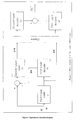
- FIG. 1 shows a block diagram of the encoding and video packet construction according to the invention, wherein FIG. 1 a is a block diagram of a hybrid DCT encoder, and FIG. 1 b is a block diagram of the organization of video information for transmission over the ATM network.
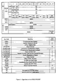
- FIG. 2 presents the organizational content of a video information packet.
- FIG. 3 is a block diagram showing the information extraction and decoding on the received side of an ATM network, wherein FIG. 3 a is a block diagram of the decoding and error concealment portion of the ATM receiving network, and FIG. 3 b is a block diagram of the information extraction portion of the received network.
- FIG. 4 presents an example of an recursive structure, showing a block diagram of a two-layer encoder/decoder;
- FIG. 5 a presents an organization of a video information packet; and
- FIG. 5 b presents an organization of M video information packets.
- According to what has been said above and particularly with respect to the localization of the coded signals, the compression techniques that can be used to carry out a redundancy reduction of the video (e.g., television) signal to produce the compacted signal must guarantee a coding that is carried independently in each field in parts of the images termed as "blocks", so that the loss of some blocks does not interfere with the decoding of the remaining blocks which are received correctly. Therefore, the encoders used in the system are preferably selected from a group of encoders that utilize adaptive prediction schemes, such schemes typically being intrafield, interpolated interfield and interframe, with a choice of motion compensation or no motion compensation, all based on the segmentation of the image into blocks.
- It is well known that a very efficient means for television signal coding is to use the interpolated interfield and the interframe types of adaptive prediction schemes. Motion compensation using "block matching" are generally added to improve efficiency.
- For changes of scene or for fast motions an intrafield adaptive prediction scheme is preferably used; the intrafield coding should be imposed periodically following an operation signal "refresh" in order to avoid the accumulation of errors that are necessarily connected to the prediction scheme. It is well known that the hybrid coding schemes combine the temporal, prediction with domain transform operations to achieve respectively a reduction in the temporal correlation as well as in the spatial correlation. The bi-dimensional cosine transform is normally utilized which allows use of fast algorithms that implicitly leads to segmentation of the video image into blocks.
- In order to better understand the problem, reference is made to the structure used in a transmission network involving a conventional hybrid encoder, such as that as has been described by S. Cucchi and F. Molo in "DCT Based Television Coding" for "DS 3 Digital Television", SMPTE, October 1988, and has been indicated in FIG. 1(a). The encoder of FIG. 1(a) is now described proceeding generally from its left to right side.
- Input blocks b i belong to the field under analysis f i are inputted along line S1 into the positive terminal of adder A1. In all algorithms based on adaptive prediction schemes, a search is made of the block belonging to the preceding interpolated field; or to the preceding frame (both inputted to comparator B7 which provides the output line S2 to the negative terminal of adder A1), which gives the better prediction of the block under test. Thus, the input S2 represents the estimated block while input S1 represents the actual input block. Among the various possible selections, the one that is preferred is that which supplies a prediction error (output S3 from adder A1) equal to the distance between the input blocks at S1 and the estimated block at S2, with a minimum energy content. The comparison criteria among the various possible selections are based on energy measurements and crossed comparisons or are made with respect to thresholds.
- Comparator B7 also receives the input block under test, for example, block b i as shown in FIG. 1(a). The possible prediction blocks are inputted to comparator B7 along lines S5, S6 and S7 coming from interpolator B9, field memory f-2, B10 and motion estimate B11, respectively. Motion estimator B11 provides an estimate of the movement for the motion compensation. The goal is the transmission of the prediction error having the minimum information content (output S3 from adder A1). This implies for a correct reconstruction on the reception side the transmission of the information around the selected predictor which is outputted from comparator B7 as "selection" along line S8.
- In the case of prediction with motion compensation, the chosen motion vectors, outputted from comparator B7 along line S10 based upon the input received from motion estimated B11 along line S7 by the comparator, the chosen motion vectors are also included as output S10 with the selected predictor at S8. In addition, if signal refresh information is inputted at line S4 to comparator B7, then that information is also sent as output information at line S9 from comparator B7.
- The selected prediction error at S3 is inputted to Hybrid DCT Encoder B1 where the selected prediction error is subjected to a Discrete Cosine Transform (DCT) domain transformation, with the output signal thereafter being inputted to scaling and quantization module B2 where the scaling applied at B2 weighs the psychovisual contribution of the various transformed coefficients.
- Different types of quantizers are selected at B2 in an adaptive manner in order to guarantee a signal to noise ratio which is almost constant on the average and is decided by the input provided at B2 from quality control module B3. The quantization also depends on the state of the encoder-ATM network interface video packet buffer memory B15 as indicated by the signal presented through a feedback path S11 connected from B15 as input to Scaler and Quantizer B2. Buffer memory B15 allows a control of the generated bit rate, but with a reduction of the quality level, in order to adjust the encoder shown in FIG. 1 a to conform to the statistical parameters negotiated with the ATM network during the call set-up phase. The type of quantizer that is used in B2, possibly common to many blocks, presents information that is transmitted, represented by the quantization output line S12 from module B2.
- On the transmission side, and congruously on the reception side, the quantized prediction error, output line S13 from module B2, is inputted to rescaling module B5 where the prediction error is rescaled in a manner similar to the scaling performed in B2, where it is then outputted to IDCT module B6 where the scaled prediction error is antitransformed and delivered as an input to adder A2 where the signal is added to the prediction block (S2) to produce a reconstructed block output from adder A2 along line S14. Obviously, the reconstructed block at S14 differs from the original block at S1 since the quantization performed at B2 is irreversible.
- The quantized prediction errors are delivered to scanner and encoder module B4 where a combination of encoding is applied to the quantized prediction error signal utilizing a combination of zeros and words with variable length. The determination of symbols to be encoded is based upon scannings of the zig-zag type or similar scannings conducted at B4. Finally, each error prediction block supplies a different information quantity, that is, a different data stream at a variable bit rate, as output from scanner and encoder B4, the ouput being indicated by line S15 in FIG. 1(a). If the motion vectors at S10 outputted from comparator B7, as discussed previously are encoded by codes with variable length words, this vector information is also generated at a variable bit rate.
- The purpose of the structuring of the video information, as discussed further below, is to package the blocks and the information associated with these blocks in one or more packets or cells in order to limit and locate the cells and packet lose.
- The video information is organized into video units. Each video unit corresponds to a space location of a prefixed dimension of the television (video) image, i.e., one having a fixed number of blocks, and each video unit is divided into a variable number of cells. For a color television image, luminance and chrominance related to the same space part are generally processed in a different manner, but are transmitted as a single video unit. The transmission order of the luminance and chrominance inside the same video unit guarantees the separation of the components, without further adding information, however, it is possible to process and transmit the luminance and chrominance on different video units. The selection of the part of the television image associated to the video unit generally depends on the type of coding system that is used and includes one or more blocks in which the same image was divided.
- A particularly advantageous and therefore preferred embodiment of the invention contemplates that for each video unit, the information to be transmitted is divided into the three different classes: a) normal information, b) privileged information, and c) auxiliary information.
- a) normal information, or the normal class, includes the prediction errors. The information outgoing from encoder B4 for all blocks belonging to a Video Unit is inserted in consecutive cells. Since the data stream generated is made of with a variable bit rate, the number of cells differs among the Video Units. This cell number is considered information belonging to the auxiliary class (discussed in subparagraph c) below).
- b) privileged information or the privileged class, includes the selections made in all the blocks belonging to a video unit, comprising the motion vectors in the case where the prediction with motion compensation is implemented together with the applied quantizer type. This kind of information can be common to all blocks forming the video unit, or it can differ among the component blocks. The privileged class also includes information common to many video units and distributed among the same video units according to a suitable assignment policy. For example, if the video unit corresponds to a stripe, the included information may be common to a field or a frame, or to many frames according to the specifications of the applicable television standard. The data stream generated by the privileged class information can be divided in part to information at a constant bit rate, typically done for the selected predictors and the type of quantizer used, and in another part, at a variable bit rate which is generally applied to the information coming from the coding with variable word length of the motion vectors. Therefore, the number of cells related to the constant bit rate can be fixed or a priori, while the number of cells related to the variable bit rate is assumed as information belonging to the auxiliary class, as discussed in the following paragraph.
- c) Auxiliary information, or the auxiliary class, includes all the information that allows a simple and efficient management of the video units in terms of the detection of lost or wrongly received cells, and the subsequent error concealment. For example, the number of cells generated by the variable bit rate data streams belonging to the normal and privileged information classes form, as indicated in the respective paragraphs above, a part of the auxiliary class.
- The remaining information depends on the protection method used for the information belonging to the various classes and on the strategy of separation for the consecutive video units.
- A video packet is formed by a two parts: a header and a body, which are associated with each video unit. The header and the body both differ in terms of the information classes which they each contain. Privileged and auxiliary information are contained in the header, and normal information is contained in the body. The contents of the header and body also differ according to the different methods of protection applied.
- FIG. 2 indicates the structure of a video packet according to the information. In this particular case, the video packet is referred to cells having a 48 byte information field (payload) available with a direct access at an ATM layer. The header (E) precedes the body (F) in FIG. 2 in the structure of the video packet. Header (E) includes: a) an identifier, b) an alignment word, c) information of the privileged class at a constant bit rate, d) information of the privileged class at a variable bit rate, e) information of the auxiliary class equal to the cell number, f) information belonging the auxiliary class developing a protection function, g) additional information, and h) a spare part. Each item is further discussed in the similarly identified paragraphs that follow.
- a) an identifier (VUI=Video Unit Identifier: e.g., 1 byte if it is assumed as an order number) provides a distinction to the video packet from subsequent video packets due to the established correspondence among video units transmitted in succession.
- b) an alignment word (HAW = Header Alignment Word: e.g., 2 bytes) allows for lost identification of the start of the video packet. The contemporously use of a similar alignment word (e.g., BAW) allows to distinguish the header from the body within the same video packet.
- c) the information of the privileged class at a constant bit rate (CBRH=Constant Bit Rate Header), typically the selected predictors and the type of quantizers related to the present video unit and to two other video units located in the original image at a suitable spatial distance. In a preferred embodiment, when the video unit is caused to correspond to a stripe, the three video units are taken at a distance of half field. For example, using a 4:2:2 format, images of 720×288 pixels per field and blocks of 8×8 samples, a stripe (e.g., representing the video unit) generates 90 luminance blocks and 90 chrominance blocks for the two color components. Then, for example, a byte can be associated with the selected predictions related to each block belonging to a quadblock y/cb/y/cr, corresponding to the same video part of a 16:8 pixel.
FIG. 2 indicates the information for the whole stripe (SC=Stripe Choice, here e.g., 45 byte; FPSC=First Previous SC; SPSC=Second Previous SC). Two different identifiers relative to the luminance and chrominance components are reserved for the type of quantizer and refresh, e.g., this information could be in common to a whole stripe (LQ/R=Luminance Quantization/Refresh: e.g., 1 byte, CQ/R=Chrominance Q/R; FPLQ/R = First Previous LQ/R, FPCQ/R; SPLQ/R = Second Previous LQ/R, SPCQ/R).
The protection on the information of the privileged class is carried out by repetition. On the received side, the information is repeated three times and is accumulated with a delay that is correlated to the pre-set space distance, then a decision at a majority byte by byte is applied. The same procedure also applies if the delay is imposed on the transmission side. - d) The information of the privileged class at a variable bit rate (VBRH=Variable Bit Rate Header), typically the motion vectors following the same implementation of protection by repetition as described in the preceding subparagraph c). This information can be related to the considered video unit and the two other video units or it can represent a part of the information in common to many video units, and after being repeated three times, is distributed among the various video units according to a suitable policy. This method also applies if the motion vectors are coated with fixed length words, in which case the number of cells can be fixed a priori not considered as auxiliary information. Moreover, this arrangement may also be extended to information having a fixed or variable bit rate in common to many video units, typically the video standard specifications (VF=Video Format: e.g., 1 byte; FPVF=First Previous VF; SPVF=Second Previous VF).
- e) the information of the auxiliary class equal to the cell number, which:
- forms the Body (F) (BNC=Body Number Cell: e.g., 2 byte; FPBNC=First Previous BNC; SPBNC=Second Previous BNC), and
- comprises the information of Header (E) at a variable bit rate, providing that it exists as indicated and discussed in the preceding subparagraph c). (HNC=Header Number Cell: e.g., 1 byte; FPHNC= First Previous HNC; SPHNC=Second Previous HNC.
The protection applies the same rule (procedure) as used in described previously in subparagraph c), as this information is associated with each Video Unit. - f) the information belonging to the auxiliary class and not indicated formally and which, according to another advantageous feature of the invention, develops a protection function into the content of Body (F). A maximum fixed number of Cyclic Redundancy Checks (CRC) protects the prediction errors that are included in the Body in order both, to allow the localization of the lost cells, and to guarantee that the received cells are exempt from errors due to the transmission channel. This feature is implemented utilizes at the same time the CRC codes, the previous BNC information belonging to the same auxiliary class and a window method. Since the Body is composed of a variety of cells, the efficiency of the CRC codes, in terms of the CRC number actually used, may be different among the video units. The CRC number depends on the locking characteristics of the system, based on recognition of the end-of-block symbols that are generated as pseudorandom sequences by suitable devices (scrambler systems). In transmission, the cells including the prediction errors related to the video unit, are scanned in succession until the necessary number of words has been accumulated so that the selected code can be recovered, or until the end of the cells of the Body. In reception, if errors are detected, then all that part of the video unit that is covered by the CRC code, which generally extends into a no integer number of cells, is deemed to be lost as though all the cells of this portion were not received. As the CRCs are related to the prediction errors of a video unit, the protection follows the same rule or procedure as described earlier in the above subparagraph c). (CRC: e.g., 3 byte; FPSRC=First Previous SRC; SPSRC - Second Previous SRC.)
- g) an additional information (VSR=Video Sync Recover, e.g., 3 byte) that allows for the recover on the reception side of the video synchronism.
- h) a residual part (SPARE) for further specifications and/or the case where the information field size of the cell is less than one initially foreseen.
- The body (F) follows the header (E) in the structure of the video packet (FIG. 2), and includes
- a') an alignment word (BAW=Body Alignment Word): e.g., 2 byte) as already discussed in the above subparagraph b).
- b') the prediction errors related to the blocks forming the video unit inserting on consecutive cells, as they are supplied by the encoder. The cell number depends on the selected quantizer and, in any case, it changes among the various video packets (VBRB = Variable Bit Rate Body) The last cell is generally filled with dummy bits in order to avoid the propagation of a video unit towards contiguous video packets.
- FIG. 1 b shows the construction of a video packet in accordance with the above-mentioned specification. The figure is examined from the left to the right side.
- Module B14 entitled Process for Video Packet Construction comprises a processor (B14) that receives the input S8, S9, S10, S12 and S16 related to the privileged information and receives input S15 related to the normal information, and adds to this information the auxiliary information generated internally in order to obtain the prefixed Video Packet format.
- The protection method used also requires a video packet memory, contained in Video Packet Constructor B14, to build the whole information associated with a video unit, e.g., a stripe and a header field memory (module B13) for the information included in the Header, and a Body Video Unit Memory (module B12) for the information included in the Body. The Video Packet Constructor B14, accumulates, in the body unit memory of B12, the prediction errors of an entire Video Unit, carries out the calculation of CRC codes, and generates the header of the video packet related to the video unit under test, using the content of Header Field Memory B13. That content of the header field memory, corresponds to the privileged and the auxiliary information of two other video units located at a spatial distance, respectively of a half field and of a whole field. To carry out the repetition of the above-described process, the privileged and auxiliary informations of the considered video unit are stored in Header Field Memory B13 in the corresponding locations.
- The cells forming a video packet are delivered to the ATM network through a video packet buffer memory B15 following a suitable strategy. As stated above, the presence of buffer memory B15 allows an adjustment of the bit rate generated by the encoder shown in FIG. 1 a in order to conform to the statistical parameter negotiated with the network during the call set-up phase (feedback signal delivered as output from B15 along line S11 as input to scaler and quantizer B2). This adjustment may be forced by the presence of a congestion signal coming from the network to the encoder (as indicated by dotted line S17 in FIGS. 1 a and 1 b) if this signal is foreseen.
- The error concealment is based on the assumption of replacing, upon reception of the signal, the reconstructed block with the prediction block, if the prediction error is not received or if it is deemed to be wrong.
- The prediction block selected in transmission and belonging to the previous interpolated field or to the previous frame in the position given by the motion vectors is the block that best estimates the block of the test or, equivalently that which supplies a prediction error with a minimum energy content.
- In case of an unforced intrafield selection that is not coming from the refresh signal (input line S9), the prediction block does not exist because the prediction error coincides with the block on the test. Therefore, it assumes to take from the frame memory on the reception side the nearest homologous block that belongs to the preceding interpolated field. However, it can also take the block that is in the same spatial location but belongs to the preceding frame.
- In case of a forced intrafield selection, that is coming from the refresh input signal (S9), if the selected predictors used in the absence of the refresh signal always transmitted together with the information of the refresh signal (1 bit for each block or less, as generally the refresh is forced on image parts), it is possible to drop down into the general procedure of replacement with the prediction block that supplies the best estimate. This concealment method requires that the selections, together with the motion vectors in the case of prediction with motion compensation, are received correctly for each block belonging to a Video Unit. This correction in reception is guaranteed by the repetition of this information for three times, and by the majority decision.
- As in transmission, we now refer to the structure on the reception side of a hybrid encoder with error concealment that uses the format of the established video packet, as presented by the block diagram of FIG. 3 b. FIG. 3 is analyzed from its left to right side in the following paragraph:
- 1c) Receiving video packet buffer B1' receives and collections the cells, intended as the only information field delivered to the ATM network
- 2c) the cells are delivered from receiving buffer B1' to an video packet analysis and extraction unit B2'. The analysis made by Unit B2' on the alignment words (HAW and BAW) and on the identifier of the video unit (VUI), both included in an univocal manner into the video packets, allows to distinguish the contiguous packets, and also to distinguish the header and body inside the same packets. The video packets received and identified are stored in different locations, respectively for the header and for the body. For example, if the video unit corresponds to a stripe, the repetition of the privileged information and the auxiliary information in the header of three different packets interlaced on the distance of a field, requires at least a local memory and a field memory associated with the header. If, for example, analysis and extraction unit B2' is charged with the task of distinguishing the privileged and auxiliary information related to the three video units included in the Header of the video packet under test, it is possible to make the comparison operations easier. In fact, this classified information may be stored in three field memories, by means of a three header field memories B3', each memory therein representing one of the three repetitions, in the locations corresponding to the associated video units.
On the contrary, the prediction errors included in the body are accumulated in a body field memory B4' of at least one field. The circularly management of memory B4' is performed by means of a tables of pointers B5' associated with the video units to make possible the distinction among the body belonging to contiguous video packets.
The loss of cells comprising the alignment words (HAW and BAW) for the identifiers of the video unit (VU) allows a delayed identification and an incomplete storage of the video packet. - 3c) By means of a header majority decoding module B6', the privileged and the auxiliary information associated with a video unit is obtained after a delay at least equal to the storage of the three repetitions distributed into the Headers of the video packets, by using a majority decision byte by byte on the above-mentioned information content, repeated for three times.
For example, using a video unit equal to a stripe and a delay of a field, it is possible for each identified video unit to obtain the checked privileged and auxiliary information of the video unit located in the homologue position of the received unit, but at a distance of a field, using a structure with three memories as indicated and described in the preceding subparagraph 2c). If the privileged and the auxiliary information of the received video unit is locally stored in the video packet analysis and extraction module B2', the majority decision is carried out using the contents of the three memories in the location of the Video Unit under test equal to the received one. Subsequently, the content of the local memory is unloaded into the same location of the three header field memories module B3', representing the first repetition, in order to allow for the repetition possibility of the operations.
It is well noted that the delay necessary to accumulate the three repetitions is here placed in the reception network, and the operations according to the block diagram shown in 1 a and 3 b are based on this assumption. However, it is possible to move this delay towards the transmission side with some minor modification of the devices or modules previously described. In that case, for example, it is advisable to exchange the memories related to the body between the transmission and receiving sides.
Header majority decoder B6' performs a comparison that provides the privileged and the auxiliary information for the video unit under test. Information included in the header (VBRH) related to the cell number at a variable bit rate (HNC) allows a verification of whether the quantity of arrived cells is exact and to take, a posteriori the majority decision that therefore, is initially applied only to the constant bit rate part (CBRH). The information rated to the cell number of the body (BNC) allows the BNC and CRC comparison unit B8' that receives the outputs of body field memory B4' and the table of pointers B5', to establish if the received cell quantity is correct. Moreover, the same device can localize the last cells and recognize if the received cells are wrong by use of the extracted CRC codes, the BNC and a suitable window method.
In case of detected errors, the whole part of the body covered by the CRC code is rejected and is generally extended into a NO integer number of cells. - 4c) the unpacking of video packet is followed by its respective video unit reconstruction, in terms of the prediction errors outputted at line S6' from the video unit reconstruction module B7' and the information associated with the video unit.
- Header majority decoder B6' provides the privileged information, such as the selected predictors outputted along selection line S2', the motion vectors outputted at line S4' in the case of prediction with motion compensation, the quantization step size is indicated by quantization output line S5', the refresh output at line S3' and the video format outputted at line S1'. Video unit reconstruction module B7' restores the normal information format supplying a signal of valid or invalid data, as indicated by output line S7' from module B7', respectively in conjunction with corrected or lost prediction errors outputted at line S6' from module B7', where lost errors mean errors not received or wrong ones.
- The decoding scheme with error concealment is presented by the block diagram of FIG. 3 a, which is described as follows:
- 1d) in the case of valid data, i.e., exact prediction error, the scheme follows the usual structure of a hybrid decoder, in accordance with what has been previously described in the earlier subparagraph 4a).
- 2d) in the case of invalid data, the prediction error is not added to the prediction block (switch module B10') and therefore the reconstructed block is exactly the same as the prediction block. Moreover, the search performed by predictor selector B9' of the prediction block which received the data valid information by output line S6' from module B7'is different from the usual structure as described earlier in subparagraph 1d) for the intrafield selection. As has already been pointed out, in case a refresh signal equal to a forced intrafield signal, the prediction block corresponding to the best selection is supplied. However, in the case of an intrafield signal coming from the selection, the prediction block supplied is the one nearest homologous block. As there does not exist a dialogue between the receiving and the transmitting side, this error concealment diversifies the image reconstruction of the transmitter with respect to the receiver. This fact imposes even more for the use of the refresh signal (or data rate) in order to guarantee the identity of operation between the transmission and reception systems. In any case, the refresh rate depends on the probability of cell lose that characteristics the network.
- A generalization both of the video packet and of the structure related to the formation of the video information in transmission and to the extraction of the same information in reception, allows advantageously for the use of the so-called progressive encoders. As is well known, progressive encoders allow the transmission of images using following refinements, namely that it must be emphasized that the information related to enhancement of the signal is independent from the information that guarantees a prefixed quality of the reconstructed signal. Such progressive encoding is implicit in the sub Band method as has been described, for example, by D. Karlsson in the article, "Sub Band Coding of Video for Packet Networks", Optical Eng., July 1988. On the other hand, in case the casine bi-dimensional transformers applied to the image segmented in blocks, for example, as has been described by Lager and M. Yamazaki in the publication "Still Picture Compression Algorithms Evaluating for International Standardization", Globecom, 1988 the progressive update can be achieved through different mechanisms as the following describes.
- 1e) spectral selection: for each block, the low frequency terms provide a row version of the image, which is subsequently refined by sending more and more high frequency coefficients to arrive at the final image.
- 2e) hierarchical or pyramidal decomposition: the whole image is initially filtered and subsampled, and therefore is encoded by Adaptive DCT (ADCT); and
- 3e) recursive structure: the difference between the original image and the decoded image coming from the encoding of a lower level is recursively coded. In order to describe and simplify the problem, reference is made to the conventional structure of a recursive encoder, for example, one with two levels, as indicated in FIG. 4. See also, Ghambari, "Two layer coating of video signals for VBR networks", IEEE Journal on selected areas in communications, July 1989.
- The block diagram of a two-layer coder/decoder as shown in FIG. 4 is examined in the following paragraphs, preceding generally from its left to right side.
- 1f) First-layer coder C1 and first-layer decoder D1 can represent, e.g., respectively the hybrid DCT encoder B1 of FIG. 1 a with the same input signals S1 (original block), S14 (reconstructed block), S15 (transmitted prediction error) and the decoder of FIG. 3 a. The information of normal class transmitted and received at this level corresponds to the prediction errors.
Other coding and decoding systems belonging to the same group as the one used by way of example can represent the blocks C1 and D1 of FIG. 4. Moreover, they can supply data streams, typically the prediction errors, with a constant speed. - 2f) Second-layer encoder C2 and second-layer decoder D2 can be implemented, e.g., either using a simple pulse code modulation (PCM coding) possibly with threshold, by the transmission of only the values higher than a prefixed threshold, or by applying a spatial or temporal differential PCM (DPCM) or a domain transformation.
- The outgoing data stream S'15 from Second-Layer Encoder C2 is generally generated at variable bit rate equal to a reconstruction error and again, it can be classified as information of a normal class, but with a lower level than the output S15 from First Layer Coder C1.
- Referring to the structure of the video packet as previously described, the normal class is redefined as the class which includes the prediction errors outputted at S15 and the reconstruction errors outputted at lines S'15.
- Generally speaking, and with reference to a generical progressive coding, this class (using the symbol a) for normal class information) includes the normal information A0), A1), ..., AN), i.e., the normal information class A is stratified on the level of numbers N + 1 outgoing from the progressive encoder.
- Consequently, the body (represented as body (F)) is divided into subsections F0), F1), ..., FN), each having the same characteristics as indicated at point F)a')b') of the previous description.
- Then, in the structure of the video packet, the header is followed by the body divided by N + 1 body F0), F1) ... FN), each one including:
- a") an alignment word (BiAW=Body ith Level A W); and
- b") the information of normal class A i ), equal to the errors related to the encoder of the ith level; e.g., in the case of a recursive structure, the prediction errors for the
level 0 and the reconstruction errors for thelevel 1. - In addition, the last cell is filled with dummy bits in order to avoid inside the same video unit the propagation of the ith body on the following body and the propagation of the Video Unit onto the contiguous Video Packet.
- Now the Header includes the information of the auxiliary class equal to the number of cells making the ith bodies (BiNC= Body i Level Number Cell), as previously indicated at point Ee). Obviously, if the information of the normal class of a certain ith level has a constant bit rate, the corresponding cell number can be fixed a priori.
- The protection follows the same procedure applied at point E)e) (BiNC; FPBiNC=first previous BiNC; SPBiNV=second previous BiNC) for the information of the auxiliary class. On the contrary, the protection of the contents of the Body, according to what has previously been pointed out in E)f), can be diversified in the different bodies F0), F1) ... Fn), both for the presence or the lack of CRC codes, their type and the number and repetition (CRCi = cyclic redundancy check i level; FPRCRCi = first previous CRCi; SPCRCi=second previous CRCi).
- The structure related to the organization of the video information in transmission, and to the extraction of the same information in reception, as proposed when the stratification is not used and as shown respectively in FIGS. 1 b and 3 b, can be easily extended for being adapted to the treatment of information stratified in more levels.
- In the case of a recursive structure, the refinement of the ith level is possible only if the enhancement of the previous level was successful, that is, the use of the body Fi) involves the correct reception of the body Fi-1) belonging to previous level.
- According to that previously described with respect to the concealment technique, the error concealment is applied only if some cells belonging to the body F0 are lost or deemed wrong using the protection method already pointed out. The following bodies Fi) are specifically employed to improve the image of the previous level and they can be used only if they correctly arrived and if the information of the previous level was considered valid.
- As a further feature of the extension, it is worth noting that for transmission on packet networks, the stratification of the video information implies the generation of cell groups with a different priority and, therefore, the possibility of exploiting advantageously new generations of packet transmission networks, e.g., ATM networks, with priority.
- In the extension of the video packet structure as proposed, the bodies Fi), with increasing index i, characterize information units (and therefore cell groups) in which they are packed with a gradually decreasing priority.
- Obviously, the greatest priority belongs to the cells of the header including the privileged information and the auxiliary information of the present video unit and of the two other video units located in the original image at a suitable space distance. If the priority of the network carries out only a privileged information treatment in terms of cell loss probability, then all cells of the video packet follow the same virtual path and they are orderly delivered to the receive site with a cell loss probability that increases with the ith order of the body Fi), according to the decreasing priority.
- FIG. 5 a refers to the case of a single Video Packet including a single header (E) and a body (F) now divided according to its distinctive feature in N + 1 BODIES F0), F1) ... FN), equal to the number of stratified levels outgoing from the progressive coding. On the contrary, FIG. 5 b refers to the case in which the priority implies a cell counting on different virtual channels according to the required priority level. Then the video packet P.V., can be divided into a number (M+1) of video packets P.V.0., P.V.1, ... P.V.M., with M+1 being minor or equal to the number N+1 levels outgoing from the progressive encoder, so that many bodies Fi) can be grouped in a single video packet P.V.k, see, e.g., P.V. 1 including the bodies F1) and F2).
- Then each video unit is associated with a video packet, subdivided into )M+1) parts. Among these packets, the
video packet 0 includes at least the header E( and the Body F0), that is all information essential for the basic reconstruction of the video signal. In fact, similar to the case of a single video packet, the header E) includes the information of privileged class and auxiliary class common (e.g., VF, FPVF, SPVF) and specific for each level outgoing from the progressive encoder (e.g., BiNC, FPBiNC, SPBiNC), for each of the three video units. On the other hand, the body F0) includes the information of normal class A0), that guarantees a prefixed reproduction quality. - It is worth noting that for the used error concealment technique, the information included in the Header E) is the most important one, so it may be reserved for a better treatment to the header E) than to the body F0). Obviously, this consideration may be extended to the previous coding without stratification.
- If the network does not provide an ordered delivery of the information coming from the virtual channels the receiver structure must be further revised to allow for the combination of various information data streams included in different Video Packets. Then the generic video packet P.V.k comprising one or more bodies Fi), must be provided with an identifier of video unit (VUI), in addition to the BiAWs already present, in order to make possible the recognition of the video unit to which the video packet belongs. For example, in the case of a recursive structure with two levels, a video packet subdivided into two stratified packets is associated with each video unit. The
video packet 0 includes the header E) and the body F0), i.e., the prediction errors, and thevideo packet 1 includes the body F1), i.e., the reconstruction errors.
Claims (3)
- A video transmission system comprisingmeans for structuring video information in video units (VU) each corresponding to a fixed number of blocks of the television image, andmeans for associating a video packet comprising a header (E) and a body (F) with each video unit (VU), each video packet being suitable for being transmitted and processed by packet transmission networks which transmit data streams at variable speed,characterisedin that said structuring means is adapted to process video information that is output at variable speed by a video signal encoder, and by:means for classifying the information in each video unit (VU) as either normal or privileged and auxiliary information, said privileged and auxiliary information including information relating to more than one of said blocks, wherein said header (E) includes said privileged and auxiliary information of the associated video unit (VU) and of at least two other video units, and said body (F) includes said normal information of the associated video unit (VU),means for extracting and comparing the same information from the headers (E) of said associated video unit (VU) and said other video units to determine the accuracy of the information contained in the body (F), andmeans for concealing errors by replacing the information in the body (F) with predicted information if the information contained in the header (E) is determined to be inaccurate.
- The system of claim 1, wherein said encoder is a hybrid discrete cosine transform (DCT) encoder.
- The system of claim 1 of 2, comprising on the transmission side:a video packet constructor (B14) for receiving the information outputted by the encoder, the constructor (B14) including a body video unit memory (B12) and a header field memory (B13) to form said video packets, anda buffer (B15) for storing video packets,and on the reception side:a receiving buffer (B1') for storing transmitted video packets,analysis and extraction means (B2') for receiving data from said receiving buffer (B1') and for extracting parameters from the transmitted data to distinguish contiguous video packets and to distinguish therefrom information related to said header (E) and said body (F),a header field memory (B3') and a body field memory (B4') coupled to said analysis and extraction means (B2') for storing information related to said header (E) and body (F), respectively,means (B6') for applying a majority decoding rule to the information stored in said header field memory (B3'),means (B8') for applying error correction codes to the information stored in the body field memory (B4'),means (B7') for reconstructing a transmitted video unit (VU), andmeans for concealing errors in said reconstructed video unit (VU).
Applications Claiming Priority (4)
| Application Number | Priority Date | Filing Date | Title |
|---|---|---|---|
| IT19265A IT1239072B (en) | 1990-02-06 | 1990-02-06 | Packet structuring for processing output data from signal encoder |
| IT1926590 | 1990-02-06 | ||
| IT1960490 | 1990-03-23 | ||
| IT19804A IT1240300B (en) | 1990-03-23 | 1990-03-23 | System, packet structure and devices for processing data output from a progressive signal encoder |
Publications (3)
| Publication Number | Publication Date |
|---|---|
| EP0441168A2 EP0441168A2 (en) | 1991-08-14 |
| EP0441168A3 EP0441168A3 (en) | 1991-11-27 |
| EP0441168B1 true EP0441168B1 (en) | 1996-10-16 |
Family
ID=26327113
Family Applications (1)
| Application Number | Title | Priority Date | Filing Date |
|---|---|---|---|
| EP91100769A Expired - Lifetime EP0441168B1 (en) | 1990-02-06 | 1991-01-22 | System, packet structuring and device for processing output information from a signal encoder |
Country Status (7)
| Country | Link |
|---|---|
| US (1) | US5228028A (en) |
| EP (1) | EP0441168B1 (en) |
| JP (1) | JP2915595B2 (en) |
| DE (1) | DE69122634T2 (en) |
| DK (1) | DK0441168T3 (en) |
| ES (1) | ES2093649T3 (en) |
| GR (1) | GR3021774T3 (en) |
Cited By (1)
| Publication number | Priority date | Publication date | Assignee | Title |
|---|---|---|---|---|
| US8401089B2 (en) | 1999-07-19 | 2013-03-19 | Nokia Corporation | Video coding |
Families Citing this family (61)
| Publication number | Priority date | Publication date | Assignee | Title |
|---|---|---|---|---|
| JP2993715B2 (en) * | 1990-08-17 | 1999-12-27 | 株式会社日立製作所 | ATM switch and control method thereof |
| JPH04117882A (en) * | 1990-09-07 | 1992-04-17 | Matsushita Electric Ind Co Ltd | Moving picture coder |
| US5148272A (en) * | 1991-02-27 | 1992-09-15 | Rca Thomson Licensing Corporation | Apparatus for recombining prioritized video data |
| US5657399A (en) * | 1991-05-17 | 1997-08-12 | Canon Kabushiki Kaisha | Encoding/decoding apparatus using quantizing steps information |
| JP3069389B2 (en) * | 1991-05-27 | 2000-07-24 | 富士通株式会社 | ATM cell error handling system |
| ES2100202T3 (en) * | 1991-08-28 | 1997-06-16 | Alcatel Bell Nv | CODING PROVISION. |
| JP2867807B2 (en) * | 1991-08-28 | 1999-03-10 | 日本電気株式会社 | Video signal encoding / decoding system |
| EP0542261B1 (en) * | 1991-11-12 | 1998-10-21 | Nippon Hoso Kyokai | Method of performing high efficiency coding of image signal and system therefor |
| US5355450A (en) * | 1992-04-10 | 1994-10-11 | Avid Technology, Inc. | Media composer with adjustable source material compression |
| WO1993012613A1 (en) * | 1991-12-13 | 1993-06-24 | Avid Technology, Inc. | Quantization table adjustment |
| JPH05207442A (en) * | 1992-01-30 | 1993-08-13 | Matsushita Electric Ind Co Ltd | Coder for animation signal |
| KR960006762B1 (en) * | 1992-02-29 | 1996-05-23 | 삼성전자주식회사 | 2-dimensional data scanning selecting circuit for image coding |
| US5293229A (en) * | 1992-03-27 | 1994-03-08 | Matsushita Electric Corporation Of America | Apparatus and method for processing groups of fields in a video data compression system |
| US5825765A (en) * | 1992-03-31 | 1998-10-20 | Fore Systems, Inc. | Communication network based on ATM for general purpose computers |
| US5377195A (en) * | 1992-04-02 | 1994-12-27 | Telefonaktiebolaget L M Ericsson | Leaky bucket for supervision in industrial processes |
| US5289276A (en) * | 1992-06-19 | 1994-02-22 | General Electric Company | Method and apparatus for conveying compressed video data over a noisy communication channel |
| US6226327B1 (en) | 1992-06-29 | 2001-05-01 | Sony Corporation | Video coding method and apparatus which select between frame-based and field-based predictive modes |
| TW241416B (en) * | 1992-06-29 | 1995-02-21 | Sony Co Ltd | |
| JPH0622301A (en) * | 1992-06-30 | 1994-01-28 | Sony Corp | Picture corder |
| JPH0662389A (en) * | 1992-08-04 | 1994-03-04 | Matsushita Electric Ind Co Ltd | Video signal encoder |
| JPH08511385A (en) * | 1993-04-16 | 1996-11-26 | データ トランスレイション,インコーポレイテッド | Adaptive image compression using variable quantization |
| WO1994024809A1 (en) * | 1993-04-16 | 1994-10-27 | Data Translation, Inc. | Adaptive video decompression |
| JPH06311496A (en) * | 1993-04-26 | 1994-11-04 | Sony Corp | Method and device for transmitting picture signal |
| EP0625853B1 (en) * | 1993-05-21 | 1999-03-03 | Nippon Telegraph And Telephone Corporation | Moving image encoder and decoder |
| WO1995003674A1 (en) * | 1993-07-19 | 1995-02-02 | British Telecommunications Public Limited Company | Detecting errors in video images |
| JP2862064B2 (en) * | 1993-10-29 | 1999-02-24 | 三菱電機株式会社 | Data decoding device, data receiving device, and data receiving method |
| JP2902284B2 (en) * | 1993-11-12 | 1999-06-07 | ケイディディ株式会社 | Video encoding device |
| US5376969A (en) * | 1993-11-15 | 1994-12-27 | Rca Thomson Licensing Corporation | Method and apparatus for conveying compressed video data over a noisy communication channel |
| JP4357594B2 (en) * | 1993-11-30 | 2009-11-04 | ゼネラル・エレクトリック・カンパニイ | Pack data processor in transport data packet assembly system |
| JP3360922B2 (en) * | 1994-04-11 | 2003-01-07 | 株式会社日立製作所 | Moving image communication system, image restoration device thereof, and image restoration method thereof |
| US5541852A (en) * | 1994-04-14 | 1996-07-30 | Motorola, Inc. | Device, method and system for variable bit-rate packet video communications |
| US5940130A (en) * | 1994-04-21 | 1999-08-17 | British Telecommunications Public Limited Company | Video transcoder with by-pass transfer of extracted motion compensation data |
| EP0687112B1 (en) | 1994-06-08 | 2006-09-20 | Matsushita Electric Industrial Co., Ltd. | Image conversion apparatus |
| JP3046224B2 (en) * | 1994-07-26 | 2000-05-29 | 三星電子株式会社 | Constant bit rate coding method and apparatus and tracking method for fast search using the same |
| JP3628359B2 (en) * | 1994-10-19 | 2005-03-09 | 株式会社日立製作所 | Data transfer method, data transmission device, data reception device, and video mail system |
| JP3058028B2 (en) * | 1994-10-31 | 2000-07-04 | 三菱電機株式会社 | Image encoded data re-encoding device |
| US5583863A (en) * | 1995-01-31 | 1996-12-10 | Bell Atlantic Network Services, Inc. | Full service network using asynchronous transfer mode multiplexing |
| US5627836A (en) * | 1995-01-31 | 1997-05-06 | Bell Atlantic Network Services, Inc. | VPI/VCI administration |
| US20010002851A1 (en) * | 1995-04-14 | 2001-06-07 | Takao Shimada | Multimedia data processing system in network |
| US6493838B1 (en) * | 1995-09-29 | 2002-12-10 | Kabushiki Kaisha Toshiba | Coding apparatus and decoding apparatus for transmission/storage of information |
| US6571361B1 (en) * | 1995-09-29 | 2003-05-27 | Kabushiki Kaisha Toshiba | Encoder and decoder |
| US6075768A (en) * | 1995-11-09 | 2000-06-13 | At&T Corporation | Fair bandwidth sharing for video traffic sources using distributed feedback control |
| US5703877A (en) * | 1995-11-22 | 1997-12-30 | General Instrument Corporation Of Delaware | Acquisition and error recovery of audio data carried in a packetized data stream |
| FR2743245B1 (en) * | 1995-12-29 | 1998-01-23 | Thomson Multimedia Sa | DEMULTIPLEXING DEVICE |
| US6163573A (en) * | 1996-12-12 | 2000-12-19 | Sony Corporation | Equipment and method for compressing picture data |
| JPH11154954A (en) | 1997-11-20 | 1999-06-08 | Hitachi Ltd | Atm switch |
| JP3483751B2 (en) * | 1997-12-18 | 2004-01-06 | 三菱電機株式会社 | Motion vector detecting device and motion vector detecting method |
| AU6206898A (en) * | 1998-01-02 | 1999-07-26 | Nokia Networks Oy | A method for synchronization adaptation of asynchronous digital data streams |
| US6445717B1 (en) | 1998-05-01 | 2002-09-03 | Niwot Networks, Inc. | System for recovering lost information in a data stream |
| KR100587280B1 (en) * | 1999-01-12 | 2006-06-08 | 엘지전자 주식회사 | apparatus and method for concealing error |
| GB2347038A (en) * | 1999-02-18 | 2000-08-23 | Nokia Mobile Phones Ltd | A video codec using re-transmission |
| US6535525B1 (en) * | 1999-06-10 | 2003-03-18 | Unisys Corporation | Method of transmitting streams of video data, in multi-length frames, at a single average bit rate |
| JP3630590B2 (en) * | 1999-08-25 | 2005-03-16 | 沖電気工業株式会社 | Decoding device and transmission system |
| US7218680B1 (en) * | 2000-02-29 | 2007-05-15 | Texas Instruments Incorporated | Retransmission techniques for enhanced performance in fading wireless communication channels |
| DE10022262A1 (en) * | 2000-05-08 | 2001-12-06 | Siemens Ag | Method and arrangement for coding or decoding a sequence of pictures |
| KR100814431B1 (en) * | 2001-04-25 | 2008-03-18 | 삼성전자주식회사 | Apparatus for transmitting broadcast signal, encoding system for encoding broadcast signal adapted variable bit rate and decoding system thereof |
| EP1286551A1 (en) * | 2001-07-17 | 2003-02-26 | Telefonaktiebolaget L M Ericsson (Publ) | Error concealment for image information |
| ATE311727T1 (en) * | 2001-08-03 | 2005-12-15 | Koninkl Philips Electronics Nv | AUDIO-VIDEO TRANSMISSION PRIVACY SYSTEM AND PROCEDURES |
| US6990147B2 (en) * | 2001-10-23 | 2006-01-24 | Thomson Licensing | Generating a non-progressive dummy bidirectional predictive picture |
| JP2005507590A (en) * | 2001-10-26 | 2005-03-17 | コーニンクレッカ フィリップス エレクトロニクス エヌ ヴィ | Spatial expandable compression |
| US7769045B2 (en) * | 2004-03-10 | 2010-08-03 | Motorola, Inc. | Method and apparatus for processing header bits and payload bits |
Family Cites Families (8)
| Publication number | Priority date | Publication date | Assignee | Title |
|---|---|---|---|---|
| US4383272A (en) * | 1981-04-13 | 1983-05-10 | Bell Telephone Laboratories, Incorporated | Video signal interpolation using motion estimation |
| JPS58127488A (en) * | 1982-01-25 | 1983-07-29 | Kokusai Denshin Denwa Co Ltd <Kdd> | Adaptation predicting coding system of television signal |
| US4649541A (en) * | 1984-11-21 | 1987-03-10 | The United States Of America As Represented By The Administrator Of The National Aeronautics And Space Administration | Reed-Solomon decoder |
| DE3538735A1 (en) * | 1985-10-31 | 1987-05-07 | Bosch Gmbh Robert | METHOD AND CIRCUIT ARRANGEMENT FOR HIDDEN ERRORS IN A DIGITAL VIDEO SIGNAL |
| JPS62230281A (en) * | 1986-03-31 | 1987-10-08 | Toshiba Corp | Picture transmission system |
| US4851906A (en) * | 1986-11-04 | 1989-07-25 | Nec Corporation | Data compression using orthogonal transform and vector quantization |
| IT1228109B (en) * | 1988-12-21 | 1991-05-28 | Telettra Spa M | PACKAGE PREMULTIPLATION SYSTEM AND DEVICE FOR TRANSMISSION OF MULTIPLE DATA FLOWS GENERATED BY A SINGLE ALGORITHM |
| US5043808A (en) * | 1990-03-19 | 1991-08-27 | At&T Bell Laboratories | High definition television arrangement employing motion compensated prediction error signals |
-
1991
- 1991-01-22 DK DK91100769.8T patent/DK0441168T3/en active
- 1991-01-22 ES ES91100769T patent/ES2093649T3/en not_active Expired - Lifetime
- 1991-01-22 DE DE69122634T patent/DE69122634T2/en not_active Expired - Fee Related
- 1991-01-22 EP EP91100769A patent/EP0441168B1/en not_active Expired - Lifetime
- 1991-02-05 US US07/650,860 patent/US5228028A/en not_active Expired - Lifetime
- 1991-02-06 JP JP3035115A patent/JP2915595B2/en not_active Expired - Fee Related
-
1996
- 1996-11-26 GR GR960403166T patent/GR3021774T3/en unknown
Cited By (2)
| Publication number | Priority date | Publication date | Assignee | Title |
|---|---|---|---|---|
| US8401089B2 (en) | 1999-07-19 | 2013-03-19 | Nokia Corporation | Video coding |
| US8654863B2 (en) | 1999-07-19 | 2014-02-18 | Nokia Oy | Video coding |
Also Published As
| Publication number | Publication date |
|---|---|
| GR3021774T3 (en) | 1997-02-28 |
| US5228028A (en) | 1993-07-13 |
| DE69122634T2 (en) | 1997-05-15 |
| EP0441168A3 (en) | 1991-11-27 |
| DE69122634D1 (en) | 1996-11-21 |
| JP2915595B2 (en) | 1999-07-05 |
| DK0441168T3 (en) | 1996-11-18 |
| EP0441168A2 (en) | 1991-08-14 |
| ES2093649T3 (en) | 1997-01-01 |
| JPH0564174A (en) | 1993-03-12 |
Similar Documents
| Publication | Publication Date | Title |
|---|---|---|
| EP0441168B1 (en) | System, packet structuring and device for processing output information from a signal encoder | |
| Rijkse | H. 263: Video coding for low-bit-rate communication | |
| US5241382A (en) | Digital HDTV data packet format and receiver therefor | |
| EP0901288B1 (en) | Moving image coding method and apparatus | |
| US5532744A (en) | Method and apparatus for decoding digital video using parallel processing | |
| EP0912063B1 (en) | A method for computational graceful degradation in an audiovisual compression system | |
| US5438374A (en) | System and method for filtering video signals | |
| EP0732856B1 (en) | Hierarchical video encoder and decoder | |
| EP2285122B1 (en) | A method and device for reconstructing a sequence of video data after transmission over a network | |
| EP0615384A2 (en) | Adaptive compression of digital video data | |
| US5771081A (en) | Bit system for transmitting digital video data | |
| US6882686B2 (en) | System and method for object-oriented video processing | |
| US7603610B2 (en) | Coding a video data stream with unequal error protection based activity | |
| Reibman | DCT-based embedded coding for packet video | |
| US7656949B1 (en) | Methods and apparatus for performing efficient inverse transform operations | |
| US7079582B2 (en) | Image coding apparatus and image coding method | |
| US20060109906A1 (en) | Methods and apparatus for dynamically adjusting f-codes for a digital picture header | |
| Cuenca et al. | Packing scheme for layered coding MPEG-2 video transmission over ATM based networks | |
| KR100235357B1 (en) | Pyramidal decoding apparatus for the concealment of cell loss in progressive transmission | |
| Wells | Component codec standards for high-quality digital television | |
| Modena et al. | A new data structure for variable bit rate broadcast video transmission on ATM network | |
| Achir et al. | Object-based unequal loss protection for multiobject video delivery | |
| Zhang et al. | Variable-bit-rate video transmission in the broadband ISDN environment | |
| Wada et al. | Structure packing of coded video signals for ATM networks | |
| Milani et al. | An object-oriented cognitive source coding architecture for 3D video communications |
Legal Events
| Date | Code | Title | Description |
|---|---|---|---|
| PUAI | Public reference made under article 153(3) epc to a published international application that has entered the european phase |
Free format text: ORIGINAL CODE: 0009012 |
|
| AK | Designated contracting states |
Kind code of ref document: A2 Designated state(s): BE CH DE DK ES FR GB GR LI NL SE |
|
| PUAL | Search report despatched |
Free format text: ORIGINAL CODE: 0009013 |
|
| AK | Designated contracting states |
Kind code of ref document: A3 Designated state(s): BE CH DE DK ES FR GB GR LI NL SE |
|
| 17P | Request for examination filed |
Effective date: 19920427 |
|
| RAP1 | Party data changed (applicant data changed or rights of an application transferred) |
Owner name: ALCATEL ITALIA SOCIETA PER AZIONI |
|
| 17Q | First examination report despatched |
Effective date: 19940323 |
|
| GRAH | Despatch of communication of intention to grant a patent |
Free format text: ORIGINAL CODE: EPIDOS IGRA |
|
| GRAH | Despatch of communication of intention to grant a patent |
Free format text: ORIGINAL CODE: EPIDOS IGRA |
|
| GRAA | (expected) grant |
Free format text: ORIGINAL CODE: 0009210 |
|
| AK | Designated contracting states |
Kind code of ref document: B1 Designated state(s): BE CH DE DK ES FR GB GR LI NL SE |
|
| REG | Reference to a national code |
Ref country code: CH Ref legal event code: NV Representative=s name: TROESCH SCHEIDEGGER WERNER AG |
|
| REG | Reference to a national code |
Ref country code: DK Ref legal event code: T3 |
|
| REF | Corresponds to: |
Ref document number: 69122634 Country of ref document: DE Date of ref document: 19961121 |
|
| ET | Fr: translation filed | ||
| REG | Reference to a national code |
Ref country code: ES Ref legal event code: FG2A Ref document number: 2093649 Country of ref document: ES Kind code of ref document: T3 |
|
| REG | Reference to a national code |
Ref country code: GR Ref legal event code: FG4A Free format text: 3021774 |
|
| PLBE | No opposition filed within time limit |
Free format text: ORIGINAL CODE: 0009261 |
|
| STAA | Information on the status of an ep patent application or granted ep patent |
Free format text: STATUS: NO OPPOSITION FILED WITHIN TIME LIMIT |
|
| 26N | No opposition filed | ||
| PGFP | Annual fee paid to national office [announced via postgrant information from national office to epo] |
Ref country code: NL Payment date: 19991216 Year of fee payment: 10 |
|
| PGFP | Annual fee paid to national office [announced via postgrant information from national office to epo] |
Ref country code: CH Payment date: 19991217 Year of fee payment: 10 |
|
| PGFP | Annual fee paid to national office [announced via postgrant information from national office to epo] |
Ref country code: DK Payment date: 19991221 Year of fee payment: 10 |
|
| PGFP | Annual fee paid to national office [announced via postgrant information from national office to epo] |
Ref country code: BE Payment date: 20000107 Year of fee payment: 10 |
|
| PGFP | Annual fee paid to national office [announced via postgrant information from national office to epo] |
Ref country code: GR Payment date: 20000119 Year of fee payment: 10 |
|
| PG25 | Lapsed in a contracting state [announced via postgrant information from national office to epo] |
Ref country code: DK Free format text: LAPSE BECAUSE OF NON-PAYMENT OF DUE FEES Effective date: 20010122 |
|
| PG25 | Lapsed in a contracting state [announced via postgrant information from national office to epo] |
Ref country code: LI Free format text: LAPSE BECAUSE OF NON-PAYMENT OF DUE FEES Effective date: 20010131 Ref country code: GR Free format text: LAPSE BECAUSE OF NON-PAYMENT OF DUE FEES Effective date: 20010131 Ref country code: CH Free format text: LAPSE BECAUSE OF NON-PAYMENT OF DUE FEES Effective date: 20010131 Ref country code: BE Free format text: LAPSE BECAUSE OF NON-PAYMENT OF DUE FEES Effective date: 20010131 |
|
| BERE | Be: lapsed |
Owner name: ALCATEL ITALIA S.P.A. Effective date: 20010131 |
|
| PG25 | Lapsed in a contracting state [announced via postgrant information from national office to epo] |
Ref country code: NL Free format text: LAPSE BECAUSE OF NON-PAYMENT OF DUE FEES Effective date: 20010801 |
|
| REG | Reference to a national code |
Ref country code: CH Ref legal event code: PL |
|
| REG | Reference to a national code |
Ref country code: DK Ref legal event code: EBP |
|
| NLV4 | Nl: lapsed or anulled due to non-payment of the annual fee |
Effective date: 20010801 |
|
| REG | Reference to a national code |
Ref country code: GB Ref legal event code: IF02 |
|
| PGFP | Annual fee paid to national office [announced via postgrant information from national office to epo] |
Ref country code: DE Payment date: 20070110 Year of fee payment: 17 |
|
| PGFP | Annual fee paid to national office [announced via postgrant information from national office to epo] |
Ref country code: SE Payment date: 20070111 Year of fee payment: 17 |
|
| PGFP | Annual fee paid to national office [announced via postgrant information from national office to epo] |
Ref country code: GB Payment date: 20070119 Year of fee payment: 17 |
|
| PGFP | Annual fee paid to national office [announced via postgrant information from national office to epo] |
Ref country code: ES Payment date: 20070130 Year of fee payment: 17 |
|
| PGFP | Annual fee paid to national office [announced via postgrant information from national office to epo] |
Ref country code: FR Payment date: 20070111 Year of fee payment: 17 |
|
| EUG | Se: european patent has lapsed | ||
| GBPC | Gb: european patent ceased through non-payment of renewal fee |
Effective date: 20080122 |
|
| PG25 | Lapsed in a contracting state [announced via postgrant information from national office to epo] |
Ref country code: DE Free format text: LAPSE BECAUSE OF NON-PAYMENT OF DUE FEES Effective date: 20080801 |
|
| REG | Reference to a national code |
Ref country code: FR Ref legal event code: ST Effective date: 20081029 |
|
| PG25 | Lapsed in a contracting state [announced via postgrant information from national office to epo] |
Ref country code: GB Free format text: LAPSE BECAUSE OF NON-PAYMENT OF DUE FEES Effective date: 20080122 |
|
| PG25 | Lapsed in a contracting state [announced via postgrant information from national office to epo] |
Ref country code: SE Free format text: LAPSE BECAUSE OF NON-PAYMENT OF DUE FEES Effective date: 20080123 |
|
| REG | Reference to a national code |
Ref country code: ES Ref legal event code: FD2A Effective date: 20080123 |
|
| PG25 | Lapsed in a contracting state [announced via postgrant information from national office to epo] |
Ref country code: FR Free format text: LAPSE BECAUSE OF NON-PAYMENT OF DUE FEES Effective date: 20080131 |
|
| PG25 | Lapsed in a contracting state [announced via postgrant information from national office to epo] |
Ref country code: ES Free format text: LAPSE BECAUSE OF NON-PAYMENT OF DUE FEES Effective date: 20080123 |