EP0441384A2 - Readily exchangeable perfusion catheter - Google Patents
Readily exchangeable perfusion catheter Download PDFInfo
- Publication number
- EP0441384A2 EP0441384A2 EP91101706A EP91101706A EP0441384A2 EP 0441384 A2 EP0441384 A2 EP 0441384A2 EP 91101706 A EP91101706 A EP 91101706A EP 91101706 A EP91101706 A EP 91101706A EP 0441384 A2 EP0441384 A2 EP 0441384A2
- Authority
- EP
- European Patent Office
- Prior art keywords
- catheter
- proximal
- distal
- guidewire
- guidewire port
- Prior art date
- Legal status (The legal status is an assumption and is not a legal conclusion. Google has not performed a legal analysis and makes no representation as to the accuracy of the status listed.)
- Granted
Links
Images
Classifications
-
- A—HUMAN NECESSITIES
- A61—MEDICAL OR VETERINARY SCIENCE; HYGIENE
- A61M—DEVICES FOR INTRODUCING MEDIA INTO, OR ONTO, THE BODY; DEVICES FOR TRANSDUCING BODY MEDIA OR FOR TAKING MEDIA FROM THE BODY; DEVICES FOR PRODUCING OR ENDING SLEEP OR STUPOR
- A61M25/00—Catheters; Hollow probes
- A61M25/10—Balloon catheters
- A61M25/104—Balloon catheters used for angioplasty
-
- A—HUMAN NECESSITIES
- A61—MEDICAL OR VETERINARY SCIENCE; HYGIENE
- A61M—DEVICES FOR INTRODUCING MEDIA INTO, OR ONTO, THE BODY; DEVICES FOR TRANSDUCING BODY MEDIA OR FOR TAKING MEDIA FROM THE BODY; DEVICES FOR PRODUCING OR ENDING SLEEP OR STUPOR
- A61M25/00—Catheters; Hollow probes
- A61M25/0043—Catheters; Hollow probes characterised by structural features
- A61M2025/0063—Catheters; Hollow probes characterised by structural features having means, e.g. stylets, mandrils, rods or wires to reinforce or adjust temporarily the stiffness, column strength or pushability of catheters which are already inserted into the human body
-
- A—HUMAN NECESSITIES
- A61—MEDICAL OR VETERINARY SCIENCE; HYGIENE
- A61M—DEVICES FOR INTRODUCING MEDIA INTO, OR ONTO, THE BODY; DEVICES FOR TRANSDUCING BODY MEDIA OR FOR TAKING MEDIA FROM THE BODY; DEVICES FOR PRODUCING OR ENDING SLEEP OR STUPOR
- A61M25/00—Catheters; Hollow probes
- A61M25/01—Introducing, guiding, advancing, emplacing or holding catheters
- A61M2025/0183—Rapid exchange or monorail catheters
-
- A—HUMAN NECESSITIES
- A61—MEDICAL OR VETERINARY SCIENCE; HYGIENE
- A61M—DEVICES FOR INTRODUCING MEDIA INTO, OR ONTO, THE BODY; DEVICES FOR TRANSDUCING BODY MEDIA OR FOR TAKING MEDIA FROM THE BODY; DEVICES FOR PRODUCING OR ENDING SLEEP OR STUPOR
- A61M25/00—Catheters; Hollow probes
- A61M25/01—Introducing, guiding, advancing, emplacing or holding catheters
- A61M2025/0188—Introducing, guiding, advancing, emplacing or holding catheters having slitted or breakaway lumens
-
- A—HUMAN NECESSITIES
- A61—MEDICAL OR VETERINARY SCIENCE; HYGIENE
- A61M—DEVICES FOR INTRODUCING MEDIA INTO, OR ONTO, THE BODY; DEVICES FOR TRANSDUCING BODY MEDIA OR FOR TAKING MEDIA FROM THE BODY; DEVICES FOR PRODUCING OR ENDING SLEEP OR STUPOR
- A61M25/00—Catheters; Hollow probes
- A61M25/10—Balloon catheters
- A61M2025/1043—Balloon catheters with special features or adapted for special applications
- A61M2025/107—Balloon catheters with special features or adapted for special applications having a longitudinal slit in the balloon
-
- A—HUMAN NECESSITIES
- A61—MEDICAL OR VETERINARY SCIENCE; HYGIENE
- A61M—DEVICES FOR INTRODUCING MEDIA INTO, OR ONTO, THE BODY; DEVICES FOR TRANSDUCING BODY MEDIA OR FOR TAKING MEDIA FROM THE BODY; DEVICES FOR PRODUCING OR ENDING SLEEP OR STUPOR
- A61M25/00—Catheters; Hollow probes
- A61M25/10—Balloon catheters
- A61M2025/1043—Balloon catheters with special features or adapted for special applications
- A61M2025/1097—Balloon catheters with special features or adapted for special applications with perfusion means for enabling blood circulation only while the balloon is in an inflated state, e.g. temporary by-pass within balloon
-
- A—HUMAN NECESSITIES
- A61—MEDICAL OR VETERINARY SCIENCE; HYGIENE
- A61M—DEVICES FOR INTRODUCING MEDIA INTO, OR ONTO, THE BODY; DEVICES FOR TRANSDUCING BODY MEDIA OR FOR TAKING MEDIA FROM THE BODY; DEVICES FOR PRODUCING OR ENDING SLEEP OR STUPOR
- A61M25/00—Catheters; Hollow probes
- A61M25/01—Introducing, guiding, advancing, emplacing or holding catheters
- A61M25/09—Guide wires
Definitions
- This invention generally relates to a dilatation catheter for angioplasty procedures such as percutaneous transluminal coronary angioplasty (PTCA).
- PTCA percutaneous transluminal coronary angioplasty
- a dilatation catheter having an inflatable, relatively inelastic balloon on the distal end thereof is advanced through a patient's arterial system until the balloon crosses the atherosclerotic lesion to be dilated.
- the balloon is inflated to a predetermined size with radiopaque liquid at relatively high pressures (e.g., 8 atmospheres) to dilate the stenotic region and then the balloon is deflated so that the catheter can be removed and blood flow resumed.
- a guiding catheter having a preformed distal end is first percutaneously introduced into the patient's arterial system and advanced therein until the distal tip of the guiding catheter is disposed in the appropriate ostium of the patient's coronary artery.
- a guidewire is preloaded within a dilatation catheter and both are advanced through the previously positioned guiding catheter to the distal end thereof.
- the guidewire is first advanced out of the guiding catheter into the patient's coronary anatomy until the distal end of the guidewire crosses the stenotic region to be dilated.
- the dilatation catheter is then advanced over the guidewire, with the guidewire slidably disposed within an inner lumen of the catheter until the inflatable balloon is positioned within the stenosis.
- the balloon is inflated to a relatively high pressure to dilate the stenosis and then deflated and removed over the guidewire.
- U.S. Patent No. 4,332,254 (Lundquist), U.S. Patent 4,323,071 (Simpson-Robert), U.S. 4,439,185 (Lundquist), U.S. Patent 4,468,224 (Enzmann et al.), U.S. 4,516,972 (Samson), U.S. Patent 4,538,622 (Samson et al.), U.S. 4,554,929 (Samson et al.), U.S.
- Patent 4,569,347 (Frisbie), U.S. Patent 4,571,240 (Samson et al.), U.S. Patent 4,638,805 (Powell), U.S. Patent 4,748,982 (Horzewski et al.), all of which are hereby incorporated herein in their entirety by reference thereto.
- dilatation catheters which perfuse blood through an inner lumen of the catheter which traverses the interior of the balloon when the balloon is inflated during angioplasty procedures in order to avoid ischemic conditions distal to the inflated balloon.
- dilatation catheters providing perfusion capabilities are described in U.S. Patent 4,423,725 (Baran et al.) and U.S. Patent 4,790,315 (Mueller, Jr. et al.) which are incorporated herein by reference thereto. See also, U.S. Patent 4,581,017 (Sahota).
- these perfusion dilatation catheters generally have relatively large deflated profiles and as a result they frequently are not employed in those situations where the stenoses to be treated are deep within the patient's coronary anatomy.
- a vascular catheter having an expandable member on the distal end thereof and a relatively short inner lumen therein extending in a distal portion of the catheter body between a distal guidewire port and a proximal guidewire port about 10 to about 50 cm proximal from a distal guidewire port and perfusion ports in the wall of the catheter body in fluid communication with the short inner lumen between the proximal guidewire port and the distal guidewire port in the distal end of the catheter body; the vascular catheter being advanceable over a guidewire slidably disposed within the relatively short inner lumen the expandable member on the vascular catheter being expandable to at least partially occlude a blood vessel at the location causing blood to flow through the proximal perfusion-ports and the second inner lumen and out the distal perfusion ports; the expandable member being contractible to facilitate removal of the catheter from the patient.
- the present invention is directed to a dilatation catheter which can be readily exchanged without the need for extension wires or for the replacement of the guidewire with an exchange wire and which can also perfuse blood distal to the catheter when a vascular procedure is being performed within the blood vessel which otherwise blocks the flow of blood through.
- a catheter in accordance with the invention generally has an elongated catheter body with an inflatable, relatively inelastic balloon near the distal end thereof.
- the catheter body has a first elongated inner lumen extending from the proximal end of the catheter body to the interior of the inflated balloon near the distal end thereof to deliver inflation fluid to the interior of the balloon.
- a second, much shorter inner lumen extends within the distal portion of the catheter body between a proximal guidewire port and a distal guidewire port provided in the distal end of the catheter body.
- the distal guidewire port is in the very distal tip of the catheter body and the proximal guidewire port is at least 10 cm but not more than about 50 cm from the distal guidewire port.
- the second, much shorter lumen within the catheter body is adapted to slidably receive a guidewire to facilitate the advancement of the catheter over the guidewire into the patient's coronary anatomy.
- At least one proximal perfusion port is provided in the catheter body between the proximal guidewire port and the proximal end of the balloon and at least one distal perfusion port is provided in the catheter body between the distal end of the balloon and the distal end of the catheter body.
- Both the proximal and distal perfusion ports are in fluid communication with the second smaller lumen disposed within the catheter body so that blood flows distal to the catheter when the balloon is inflated during the vascular procedure.
- the number, size and location of the perfusion ports can be varied depending upon the blood flow required, the size of the catheter and the size of the inner lumen. Typically, there may be 6 to 20 perfusion ports proximal to the balloon and about 4 to 12 perfusion ports distal to the balloon. In a preferred embodiment 10 ports are provided proximal to the balloon and 8 are provided distal to the balloon.
- the proximal end of the catheter body is provided with an adapter with at least one arm for the delivery of inflation fluid from a high pressure source thereof such as a syringe to the first inner lumen leading to the interior of the balloon for inflation purposes.
- a high pressure source thereof such as a syringe
- the catheter wall which defines at least in part the second, smaller lumen disposed within the catheter body is provided with a slit which extends from the proximal guidewire port to a location proximal to the section containing the proximal perfusion ports.
- a slit which extends from the proximal guidewire port to a location proximal to the section containing the proximal perfusion ports.
- the portion of the elongated catheter body proximal to the proximal guidewire port is provided with a stiffening member such as a rod or wire which increases the pushability of the catheter and thereby allows for more distal advancement of the catheter into the patient's coronary anatomy than previous perfusion-type catheters.
- a stiffening member such as a rod or wire which increases the pushability of the catheter and thereby allows for more distal advancement of the catheter into the patient's coronary anatomy than previous perfusion-type catheters.
- the catheter assembly of the invention In the performance of an angioplasty procedure utilizing the catheter assembly of the invention, it is preferred to preload the guidewire within the second smaller lumen of the catheter with the distal tip of the guidewire extending out of the distal tip of the catheter, and then advance the combined assembly through a guiding catheter previously disposed within the patient's vasculature with the distal tip of the guiding catheter disposed with the ostium of the patient's coronary artery.
- the guidewire is first extended out of the distal end of the guiding catheter into the patient's coronary artery until the distal tip of the guidewire crosses the stenotic region to be dilated.
- the dilatation catheter is then advanced out of the guiding catheter over the guidewire until the balloon on the dilatation catheter is positioned across the stenosis.
- the balloon is then inflated with the radiopaque liquid as conventionally practiced to dilate the stenosis.
- An alternate procedure which has been found suitable comprises first advancing the guidewire through the guiding catheter and into the desired location within the patient's coronary anatomy and then mounting the dilatation catheter of the invention on the proximal end of the guidewire and advancing the catheter over the wire to the desired location within the patient's coronary arteries.
- the balloon When the balloon is inflated, it occludes the artery and blocks normal blood flow therethrough. However, blood flows through the proximal perfusion ports, through the smaller second lumen, and then out the distal perfusion ports and the distal guidewire port located in the catheter body distal to the balloon.
- the guidewire can then be advanced back through the second lumen and out the distal end thereof so that it crosses the stenosis.
- the balloon can be inflated in the stenotic region so as to maintain the patency of the artery.
- the artery may then be held open while blood perfuses therethrough for a long enough period to allow the dissected lining to be resecured to the blood vessel wall by natural healing or to allow for surgical procedures to be initiated to correct the abrupt reclosure, such as bypass surgery.
- a second catheter should then be inserted to complete the dilation.
- the catheter of the invention can be readily replaced by holding onto the guidewire extending out the proximal end of the guiding catheter and pulling on the dilatation catheter to remove it from the patient.
- a second dilatation catheter of essentially the same construction but with a larger diameter balloon may then be mounted on the proximal end of the guidewire and then advanced over the guidewire into the stenosis for further dilation.
- the same procedures may be followed to advance a catheter having a smaller balloon to the more distal stenosis.
- the dilatation catheter in accordance with the present invention can be advanced deeply within the patient's vascular system, much further than prior perfusion catheters due to the increased pushability of the catheter.
- the catheter of the present invention allows for the long-term dilatation of stenoses which the prior perfusion catheters were unable to reach.
- catheter exchanges can be quickly and very easily performed without the need for exchange wires or extension wires required with the prior art dilatation catheters.
- the present invention is directed to a vascular catheter 10 having a elongated catheter body 11 with an inflatable balloon 12 near the distal end thereof.
- a first inner lumen 13 extends through a substantial portion of the catheter body 11 and is in fluid communication with the interior of the balloon 12.
- An adapter 14 is provided at the proximal end of the catheter body 11 which is in fluid communication with the first inner lumen 13 to direct inflation fluid from a high pressure source such as a syringe pump (not shown) to the interior of balloon 12.
- a second lumen 16 is provided in a distal portion of the catheter 10 which remains within the patient during angioplasty or other vascular procedures.
- the second lumen 16 is much shorter than the first lumen and extends between a proximal guidewire port 17 and a distal guidewire port 18 which is located at the distal tip of the catheter body.
- the proximal guidewire port 17 is located about 10 to about 50 cm, preferably about 12 to about 40 cm, from the distal guidewire port 18.
- the guidewire 20 is slidably disposed within the second inner lumen 16.
- Proximal perfusion ports 21 are provided in the catheter body 11 between the proximal end of the balloon 12 and the proximal guidewire port 17 and distal perfusion ports 22 are provided between the distal end of the balloon and the distal end of the catheter body 11.
- Perfusion ports 21 and 22 pass through the wall of the catheter body 11 which defines at least in part the second inner lumen 16 and therefore are in fluid communication therewith.
- the guidewire 20 generally includes a core member 23 and a flexible body such as a helical coil 24 on the distal portion of the core member.
- a rounded plug 25 is provided at the distal tip of the core to prevent traumatic engagement with the arterial lining.
- Stiffening rod 26 is disposed within a third lumen 27 provided in the catheter body 11 proximal to the proximal guidewire port 17 and generally extends to the proximal end of the catheter body 11.
- the third lumen 27 and the second inner lumen 16 are essentially the same lumen with a plug 28 provided therein proximally adjacent the proximal guidewire port 17.
- the distal portion of the plug 28 is in the form of a ramp 30 which can guide the guidewire 20 into or out of the second inner lumen 16.
- the wall of the catheter body 11 defining the inner lumen 16 is provided with a slit 31 from the proximal guidwire port 17 to a location proximal to the proximal perfusion port 21 through port 17.
- the first inner lumen 13 is preferably provided with a small diameter wire member 32 which prevents the retention of air bubbles at the corners of the D-shaped first lumen.
- the wire member 31 preferably does not extend along essentially the entire length of the inflation lumen 13.
- Catheter body 11 can be extruded or otherwise formed from plastic resins such as polyethylene and polyesters (e.g., Hytrel) and the balloon can be formed from polyethylene or polyethylene terephthalate resins.
- the core 23 of the guidewire 20 can be made of stainless steel and the coil 24 can be made of a more highly radiopaque material such as platinum, tungsten, palladium, ruthenium, rhenium and alloys thereof. A wide variety of other suitable materials can also be used for these components.
- the outer diameter of the catheter body 11 proximal to the perfusion section can typically range from about 0.035 to about 0.05 inch (0.89-1.30 mm.) and the perfusion section thereof can range from about 0.04 to 0.06 inch (1.02-1.52 mm.).
- Inflatable balloon diameters can range from about 1.5 to about 4.5 mm.
- the stiffening element is a rod or wire preferably with a circular transverse cross-section ranging in diameter from about 0.015 to about 0.025 inch (0.38-0.64 mm.).
- the diameter of the guidewire lumen 16 in the perfusion section of the catheter body 11 may vary from about 0.015 to about 0.045 inch (0.38-1.14 mm), but in the distal tip of the catheter it may range from about 0.015 to about 0.025 inch (0.38-0.64 mm).
- the overall length of the catheter body 11 from the distal tip to the adapter 14 may be about 130 to about 150 cm.
- the aforesaid dimensions are believed to be suitable for most coronary angioplasty procedures. Angioplasty procedures at other locations and catheters for other procedures (e. g., atherectomy procedures) may require dimensions different than those described above.
Abstract
Description
- This invention generally relates to a dilatation catheter for angioplasty procedures such as percutaneous transluminal coronary angioplasty (PTCA).
- In PTCA procedures, a dilatation catheter having an inflatable, relatively inelastic balloon on the distal end thereof is advanced through a patient's arterial system until the balloon crosses the atherosclerotic lesion to be dilated. The balloon is inflated to a predetermined size with radiopaque liquid at relatively high pressures (e.g., 8 atmospheres) to dilate the stenotic region and then the balloon is deflated so that the catheter can be removed and blood flow resumed.
- Usually a guiding catheter having a preformed distal end is first percutaneously introduced into the patient's arterial system and advanced therein until the distal tip of the guiding catheter is disposed in the appropriate ostium of the patient's coronary artery. A guidewire is preloaded within a dilatation catheter and both are advanced through the previously positioned guiding catheter to the distal end thereof. The guidewire is first advanced out of the guiding catheter into the patient's coronary anatomy until the distal end of the guidewire crosses the stenotic region to be dilated. The dilatation catheter is then advanced over the guidewire, with the guidewire slidably disposed within an inner lumen of the catheter until the inflatable balloon is positioned within the stenosis. The balloon is inflated to a relatively high pressure to dilate the stenosis and then deflated and removed over the guidewire. For a detailed description of procedures, reference is made to U.S. Patent No. 4,332,254 (Lundquist), U.S. Patent 4,323,071 (Simpson-Robert), U.S. 4,439,185 (Lundquist), U.S. Patent 4,468,224 (Enzmann et al.), U.S. 4,516,972 (Samson), U.S. Patent 4,538,622 (Samson et al.), U.S. 4,554,929 (Samson et al.), U.S. Patent 4,569,347 (Frisbie), U.S. Patent 4,571,240 (Samson et al.), U.S. Patent 4,638,805 (Powell), U.S. Patent 4,748,982 (Horzewski et al.), all of which are hereby incorporated herein in their entirety by reference thereto.
- Efforts have been made to develop dilatation catheters which perfuse blood through an inner lumen of the catheter which traverses the interior of the balloon when the balloon is inflated during angioplasty procedures in order to avoid ischemic conditions distal to the inflated balloon. For example, dilatation catheters providing perfusion capabilities are described in U.S. Patent 4,423,725 (Baran et al.) and U.S. Patent 4,790,315 (Mueller, Jr. et al.) which are incorporated herein by reference thereto. See also, U.S. Patent 4,581,017 (Sahota). However, these perfusion dilatation catheters generally have relatively large deflated profiles and as a result they frequently are not employed in those situations where the stenoses to be treated are deep within the patient's coronary anatomy.
- Additionally, in instances where there is an acute or sudden blockage of the arterial passageway after dilatation of a stenotic region, conventional dilatation non-perfusion type catheters must first be removed from the patient before a perfusion-type dilatation catheter can be advanced over the guidewire in place within the patient. Usually, such catheter exchanges require the use of an exchange wire or extension wire such as described in U. S. Patent 4,827,941 (Taylor et al.), which can add considerable time and complexity to a procedure frequently performed under emergency conditions.
- What has been needed and heretofore unavailable is a perfusion-type dilatation catheter which can quickly and easily be introduced into a patient's arterial system and which has sufficient pushability to be advanced deep within the patient's vasculature. The present invention satisfies this need.
- Disclosed herein is a vascular catheter having an expandable member on the distal end thereof and a relatively short inner lumen therein extending in a distal portion of the catheter body between a distal guidewire port and a proximal guidewire port about 10 to about 50 cm proximal from a distal guidewire port and perfusion ports in the wall of the catheter body in fluid communication with the short inner lumen between the proximal guidewire port and the distal guidewire port in the distal end of the catheter body; the vascular catheter being advanceable over a guidewire slidably disposed within the relatively short inner lumen the expandable member on the vascular catheter being expandable to at least partially occlude a blood vessel at the location causing blood to flow through the proximal perfusion-ports and the second inner lumen and out the distal perfusion ports; the expandable member being contractible to facilitate removal of the catheter from the patient.
- The present invention is directed to a dilatation catheter which can be readily exchanged without the need for extension wires or for the replacement of the guidewire with an exchange wire and which can also perfuse blood distal to the catheter when a vascular procedure is being performed within the blood vessel which otherwise blocks the flow of blood through.
- A catheter in accordance with the invention generally has an elongated catheter body with an inflatable, relatively inelastic balloon near the distal end thereof. The catheter body has a first elongated inner lumen extending from the proximal end of the catheter body to the interior of the inflated balloon near the distal end thereof to deliver inflation fluid to the interior of the balloon. A second, much shorter inner lumen extends within the distal portion of the catheter body between a proximal guidewire port and a distal guidewire port provided in the distal end of the catheter body. The distal guidewire port is in the very distal tip of the catheter body and the proximal guidewire port is at least 10 cm but not more than about 50 cm from the distal guidewire port. The second, much shorter lumen within the catheter body is adapted to slidably receive a guidewire to facilitate the advancement of the catheter over the guidewire into the patient's coronary anatomy.
- At least one proximal perfusion port is provided in the catheter body between the proximal guidewire port and the proximal end of the balloon and at least one distal perfusion port is provided in the catheter body between the distal end of the balloon and the distal end of the catheter body. Both the proximal and distal perfusion ports are in fluid communication with the second smaller lumen disposed within the catheter body so that blood flows distal to the catheter when the balloon is inflated during the vascular procedure. The number, size and location of the perfusion ports can be varied depending upon the blood flow required, the size of the catheter and the size of the inner lumen. Typically, there may be 6 to 20 perfusion ports proximal to the balloon and about 4 to 12 perfusion ports distal to the balloon. In a preferred
embodiment 10 ports are provided proximal to the balloon and 8 are provided distal to the balloon. - The proximal end of the catheter body is provided with an adapter with at least one arm for the delivery of inflation fluid from a high pressure source thereof such as a syringe to the first inner lumen leading to the interior of the balloon for inflation purposes.
- Preferably, the catheter wall which defines at least in part the second, smaller lumen disposed within the catheter body is provided with a slit which extends from the proximal guidewire port to a location proximal to the section containing the proximal perfusion ports. The purpose of this slit as described in U.S. Patent 4,748,982 (Horzewski et al.), previously incorporated herein, allows the guidewire to be pulled out of a significant portion of the second lumen to increase the ease in which catheters can be exchanged.
- The portion of the elongated catheter body proximal to the proximal guidewire port is provided with a stiffening member such as a rod or wire which increases the pushability of the catheter and thereby allows for more distal advancement of the catheter into the patient's coronary anatomy than previous perfusion-type catheters.
- In the performance of an angioplasty procedure utilizing the catheter assembly of the invention, it is preferred to preload the guidewire within the second smaller lumen of the catheter with the distal tip of the guidewire extending out of the distal tip of the catheter, and then advance the combined assembly through a guiding catheter previously disposed within the patient's vasculature with the distal tip of the guiding catheter disposed with the ostium of the patient's coronary artery. The guidewire is first extended out of the distal end of the guiding catheter into the patient's coronary artery until the distal tip of the guidewire crosses the stenotic region to be dilated. The dilatation catheter is then advanced out of the guiding catheter over the guidewire until the balloon on the dilatation catheter is positioned across the stenosis. The balloon is then inflated with the radiopaque liquid as conventionally practiced to dilate the stenosis.
- An alternate procedure which has been found suitable comprises first advancing the guidewire through the guiding catheter and into the desired location within the patient's coronary anatomy and then mounting the dilatation catheter of the invention on the proximal end of the guidewire and advancing the catheter over the wire to the desired location within the patient's coronary arteries.
- When the balloon is inflated, it occludes the artery and blocks normal blood flow therethrough. However, blood flows through the proximal perfusion ports, through the smaller second lumen, and then out the distal perfusion ports and the distal guidewire port located in the catheter body distal to the balloon. To maximize blood flow through the second lumen, it is preferred to withdraw the guidewire sufficiently from the dilatation catheter so that the distal portion of the guidewire remains in the second lumen but proximal to the portion of the second lumen between the proximal and distal perfusion ports. When the dilatation has been completed, the guidewire can then be advanced back through the second lumen and out the distal end thereof so that it crosses the stenosis.
- In the event of an abrupt reclosure when the dilatation catheter is deflated, such as from a dissected lining, the balloon can be inflated in the stenotic region so as to maintain the patency of the artery. The artery may then be held open while blood perfuses therethrough for a long enough period to allow the dissected lining to be resecured to the blood vessel wall by natural healing or to allow for surgical procedures to be initiated to correct the abrupt reclosure, such as bypass surgery.
- Should the catheter in place need to be replaced with another catheter, for example when the inflated diameter of the balloon on the catheter in place is too small to completely dilate a stenosis, a second catheter should then be inserted to complete the dilation. In this instance, the catheter of the invention can be readily replaced by holding onto the guidewire extending out the proximal end of the guiding catheter and pulling on the dilatation catheter to remove it from the patient. A second dilatation catheter of essentially the same construction but with a larger diameter balloon may then be mounted on the proximal end of the guidewire and then advanced over the guidewire into the stenosis for further dilation.
- A similar situation arises when a second stenosis distal to the first stenosis needs to be dilated and the balloon on the catheter used to dilate the first stenosis is too large for the distal region. The same procedures may be followed to advance a catheter having a smaller balloon to the more distal stenosis.
- The dilatation catheter in accordance with the present invention can be advanced deeply within the patient's vascular system, much further than prior perfusion catheters due to the increased pushability of the catheter. Thus, the catheter of the present invention allows for the long-term dilatation of stenoses which the prior perfusion catheters were unable to reach. Additionally, when a catheter in accordance with the present invention needs to be replaced with another catheter, such catheter exchanges can be quickly and very easily performed without the need for exchange wires or extension wires required with the prior art dilatation catheters. These and other advantages of the present invention will become more apparent from the following detailed description thereof when taken in conjunction with the attached exemplary drawings.
-
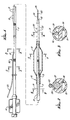
- FIGURE 1 is an elevational view partially in section of a dilatation catheter embodying features of the invention;
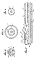
- FIGURE 2 is a transverse cross-sectional view taken along the lines 2-2 shown in FIGURE 1;
- FIGURE 3 is a transverse cross-sectional view taken along the lines 3-3 shown in FIGURE 1;
- FIGURE 4 is a transverse cross-sectional view taken along the lines 4-4 shown in FIGURE 1;
- FIGURE 5 is a transverse cross-sectional view taken along the lines 5-5 shown in FIGURE 1;
- FIGURE 6 is a transverse cross-sectional view taken along the lines 6-6 shown in FIGURE 1; and
- FIGURE 7 is a longitudinal, center line, cross-sectional view taken through the transition region of the catheter shown in FIGURE 1 illustrating the extension of the guidewire through a proximal guidewire port and into an inner lumen of the dilatation catheter.
- The present invention is directed to a
vascular catheter 10 having aelongated catheter body 11 with aninflatable balloon 12 near the distal end thereof. A firstinner lumen 13 extends through a substantial portion of thecatheter body 11 and is in fluid communication with the interior of theballoon 12. Anadapter 14 is provided at the proximal end of thecatheter body 11 which is in fluid communication with the firstinner lumen 13 to direct inflation fluid from a high pressure source such as a syringe pump (not shown) to the interior ofballoon 12. - A
second lumen 16 is provided in a distal portion of thecatheter 10 which remains within the patient during angioplasty or other vascular procedures. Thesecond lumen 16 is much shorter than the first lumen and extends between aproximal guidewire port 17 and a distal guidewire port 18 which is located at the distal tip of the catheter body. Theproximal guidewire port 17 is located about 10 to about 50 cm, preferably about 12 to about 40 cm, from the distal guidewire port 18. During the angioplasty procedures, theguidewire 20 is slidably disposed within the secondinner lumen 16. -
Proximal perfusion ports 21 are provided in thecatheter body 11 between the proximal end of theballoon 12 and theproximal guidewire port 17 anddistal perfusion ports 22 are provided between the distal end of the balloon and the distal end of thecatheter body 11.Perfusion ports catheter body 11 which defines at least in part the secondinner lumen 16 and therefore are in fluid communication therewith. - The
guidewire 20 generally includes acore member 23 and a flexible body such as ahelical coil 24 on the distal portion of the core member. Arounded plug 25 is provided at the distal tip of the core to prevent traumatic engagement with the arterial lining. During angioplasty or other vascular procedures, theproximal guidewire port 17 remains within the guiding catheter, and thecore member 23 of theguidewire 20 extends out of the proximal guidewire port and runs generally parallel to the catheter body within the guiding catheter (not shown). - Stiffening
rod 26 is disposed within athird lumen 27 provided in thecatheter body 11 proximal to theproximal guidewire port 17 and generally extends to the proximal end of thecatheter body 11. For ease of manufacturing, thethird lumen 27 and the secondinner lumen 16 are essentially the same lumen with aplug 28 provided therein proximally adjacent theproximal guidewire port 17. Preferably the distal portion of theplug 28 is in the form of aramp 30 which can guide theguidewire 20 into or out of the secondinner lumen 16. The wall of thecatheter body 11 defining theinner lumen 16 is provided with aslit 31 from theproximal guidwire port 17 to a location proximal to theproximal perfusion port 21 throughport 17. - The first
inner lumen 13 is preferably provided with a smalldiameter wire member 32 which prevents the retention of air bubbles at the corners of the D-shaped first lumen. Thewire member 31 preferably does not extend along essentially the entire length of theinflation lumen 13. - The various components of the catheter of the present invention can be made from conventional materials.
Catheter body 11 can be extruded or otherwise formed from plastic resins such as polyethylene and polyesters (e.g., Hytrel) and the balloon can be formed from polyethylene or polyethylene terephthalate resins. Thecore 23 of theguidewire 20 can be made of stainless steel and thecoil 24 can be made of a more highly radiopaque material such as platinum, tungsten, palladium, ruthenium, rhenium and alloys thereof. A wide variety of other suitable materials can also be used for these components. - For coronary angioplasty procedures, the outer diameter of the
catheter body 11 proximal to the perfusion section can typically range from about 0.035 to about 0.05 inch (0.89-1.30 mm.) and the perfusion section thereof can range from about 0.04 to 0.06 inch (1.02-1.52 mm.). Inflatable balloon diameters can range from about 1.5 to about 4.5 mm. The stiffening element is a rod or wire preferably with a circular transverse cross-section ranging in diameter from about 0.015 to about 0.025 inch (0.38-0.64 mm.). The diameter of theguidewire lumen 16 in the perfusion section of thecatheter body 11 may vary from about 0.015 to about 0.045 inch (0.38-1.14 mm), but in the distal tip of the catheter it may range from about 0.015 to about 0.025 inch (0.38-0.64 mm). The overall length of thecatheter body 11 from the distal tip to theadapter 14 may be about 130 to about 150 cm. The aforesaid dimensions are believed to be suitable for most coronary angioplasty procedures. Angioplasty procedures at other locations and catheters for other procedures (e. g., atherectomy procedures) may require dimensions different than those described above. - While the present invention has been described herein in terms of certain specifically preferred embodiments specifically directed to coronary angioplasty procedures, various modifications and improvements can be made without departing from the scope of the invention.
Claims (10)
- An intravascular catheter for performing a vascular procedure within a patient's vascular system, comprising:a) an elongated catheter body having proximal and distal ends and an expandable member proximally adjacent the distal end thereof and a relatively short inner lumen adapted to receive a guidewire which extends between a distal guidewire port provided in the distal end of the catheter body and a proximal guidewire port which is provided in the catheter body and which is disposed at least 10 cm but not more than 50 cm from the distal guidewire port;b) at least one proximal perfusion port located between the proximal guidewire port and the expandable member and at least one distal perfusion port located between the expandable member and the distal end of the catheter body, the perfusion ports being in fluid communication with the inner lumen adapted to receive a guidewire; andc) means to stiffen a portion of the catheter body proximal to the proximal guidewire port to provide the catheter with improved pushability.
- The intravascular catheter of claim 1 wherein the expandable member is an inflatable, relatively inelastic balloon suitable for dilating a stenosis and wherein the balloon is formed from a plastic resin selected from the group consisting of polyethylene and polyethylene teraphthalate.
- The intravascular catheter of claim 2 wherein the inflation lumen extends distally from the proximal end of the catheter body to the interior of the balloon and wherein the proximal guidewire port is disposed about 12 to about 40 cm from the distal guidewire port.
- The intravascular catheter of claim 1 wherein the means to stiffen the catheter body proximal to the proximal guidewire port is a rod tightly fitted within an inner lumen of the catheter body which extends from the proximal end thereof to a location proximal to the proximal guidewire port.
- The intravascular catheter of claim 4 wherein the inflation lumen has a D-shaped transverse cross-section and a thin wire extends within the D-shaped inflation lumen to prevent the retention of air bubbles in a corner of the inflation lumen.
- The intravascular catheter of claim 1 wherein a slit is provided in the wall of the catheter body defining at least in part the second inner lumen which extends from the proximal guidewire port to a location proximal to the proximal perfusion ports.
- The intravascular catheter of claim 1 wherein there are about 6 to about 20 proximal perfusion ports in the catheter wall and wherein there are about 4 to about 12 distal perfusion ports provided in the catheter wall.
- A vascular catheter having an expandable member on the distal end thereof and a relatively short inner lumen therein extending in a distal portion of the catheter body between a distal guidewire port and a proximal guidewire port about 10 to about 50 cm proximal from a distal guidewire port and perfusion ports in the wall of the catheter body in fluid communication with the short inner lumen between the proximal guidewire port and the distal guidewire port in the distal end of the catheter body;
the vascular catheter being advanceable over a guidewire slidably disposed within the relatively short inner lumen;
the expandable member on the vascular catheter being expandable to at least partially occlude a blood vessel at the location causing blood to flow through the proximal perfusion ports and the second inner lumen and out the distal perfusion ports;
the expandable member being contractible to facilitate removal of the catheter from the patient. - The catheter of claim 8 wherein the guidewire is at least partially removed from the portion of the second inner lumen between the proximal and distal perfusion ports to avoid impeding blood flow through the second inner lumen, this being done by holding the guidewire in place at a first location outside of a patient and proximally moving the catheter over the guidewire until the proximal guidewire port thereof is immediately adjacent said first holding location; and
holding the guidewire at a second location outside of a patient adjacent the distal guidewire port of the catheter and then removing the catheter from the guidewire. - The catheter of claim 8 further having a second dilatation catheter having an expandable member on the distal end thereof and a relatively short inner lumen therein extending in a distal portion of the catheter body between a distal guidewire port and a proximal guidewire port about 10 to about 50 cm proximal from the distal guidewire port and perfusion ports in the wall of the catheter body in fluid communication with the short inner lumen between the proximal guidewire port and the distal guidewire port in the distal end of the catheter body; wherein
the second dilatation catheter is mounted onto the guidewire by passing the proximal end of the guidewire through the second lumen until a portion thereof extends out of the proximal guidewire port;
holding the portion of the guidewire extending out of the proximal port of the catheter; and
advancing the catheter over the guidewire into and through the vascular system of the patient until the catheter is positioned at a desired location therein.
Applications Claiming Priority (2)
| Application Number | Priority Date | Filing Date | Title |
|---|---|---|---|
| US47605690A | 1990-02-07 | 1990-02-07 | |
| US476056 | 1990-02-07 |
Publications (3)
| Publication Number | Publication Date |
|---|---|
| EP0441384A2 true EP0441384A2 (en) | 1991-08-14 |
| EP0441384A3 EP0441384A3 (en) | 1992-02-26 |
| EP0441384B1 EP0441384B1 (en) | 1999-12-01 |
Family
ID=23890326
Family Applications (1)
| Application Number | Title | Priority Date | Filing Date |
|---|---|---|---|
| EP91101706A Expired - Lifetime EP0441384B1 (en) | 1990-02-07 | 1991-02-07 | Readily exchangeable perfusion catheter |
Country Status (4)
| Country | Link |
|---|---|
| EP (1) | EP0441384B1 (en) |
| JP (1) | JPH0584304A (en) |
| CA (1) | CA2035851A1 (en) |
| DE (1) | DE69131805T2 (en) |
Cited By (27)
| Publication number | Priority date | Publication date | Assignee | Title |
|---|---|---|---|---|
| WO1992015357A1 (en) * | 1991-03-06 | 1992-09-17 | Baxter International Inc. | Method and device for exchanging cardiovascular guide catheter while a previously inserted angioplasty guide wire remains in place |
| EP0517654A2 (en) * | 1991-06-03 | 1992-12-09 | Schneider (Europe) Ag | Catheter system to mechanically dilate the coronary stenosis |
| EP0546221A1 (en) * | 1991-12-11 | 1993-06-16 | Schneider (Europe) Ag | Balloon catheter |
| WO1993011822A1 (en) * | 1991-12-11 | 1993-06-24 | Baxter International Inc. | Rapid exchange over-the-wire catheter with breakaway feature |
| WO1993020882A1 (en) * | 1992-04-20 | 1993-10-28 | Advanced Cardiovascular Systems, Inc. | Low profile dilatation catheter |
| US5290232A (en) * | 1991-06-10 | 1994-03-01 | Cordis Corporation | Replaceable dilatation catheter |
| WO1994004216A1 (en) * | 1992-08-25 | 1994-03-03 | Bard Connaught | Dilatation catheter with stiffening wire |
| EP0586571A1 (en) * | 1991-05-24 | 1994-03-16 | G. David Jang | Multi-mode vascular catheter system |
| EP0580845A4 (en) * | 1992-02-10 | 1994-03-23 | Scimed Life Systems, Inc. | |
| WO1995002430A1 (en) * | 1993-07-15 | 1995-01-26 | Advanced Cardiovascular Systems, Inc. | Rapid exchange type intraluminal catheter with guiding element |
| US5409459A (en) * | 1993-03-12 | 1995-04-25 | C. R. Bard, Inc. | Windowed catheter and method of use |
| US5425711A (en) * | 1988-02-29 | 1995-06-20 | Scimed Life Systems, Inc. | Intravascular catheter with distal guide wire lumen and transition member |
| US5542925A (en) * | 1993-11-05 | 1996-08-06 | Advanced Cardiovascular Systems, Inc. | Dilatation catheter with oblong perfusion ports |
| US5556382A (en) * | 1995-08-29 | 1996-09-17 | Scimed Life Systems, Inc. | Balloon perfusion catheter |
| US5571087A (en) * | 1992-02-10 | 1996-11-05 | Scimed Life Systems, Inc. | Intravascular catheter with distal tip guide wire lumen |
| EP0746374A1 (en) * | 1993-10-07 | 1996-12-11 | Boston Scientific Corporation | Dilatation catheter |
| NL1000686C2 (en) * | 1995-06-28 | 1996-12-31 | Cordis Europ | Catheter for treatment of narrowed blood vessels |
| US5591129A (en) * | 1994-03-02 | 1997-01-07 | Scimed Life Systems, Inc. | Perfusion balloon angioplasty catheter |
| FR2736270A1 (en) * | 1995-07-06 | 1997-01-10 | Nycomed Lab Sa | GUIDE TYPE EXPANSION CATHETER ON A WIRE |
| EP0872257A2 (en) * | 1997-04-15 | 1998-10-21 | Schneider (Europe) GmbH | Catheter |
| US5968013A (en) * | 1997-08-21 | 1999-10-19 | Scimed Life Systems, Inc. | Multi-function dilatation catheter |
| US5971955A (en) * | 1996-06-21 | 1999-10-26 | Cordis Corporation | Double balloon catheter with ultrasonic probe |
| US6004291A (en) * | 1988-02-29 | 1999-12-21 | Scimed Life Systems, Inc. | Intravascular catheter with distal guide wire lumen and transition |
| US6013069A (en) * | 1991-05-15 | 2000-01-11 | Advanced Cardiovascular Systems, Inc. | Catheter shaft with an oblong transverse cross-section |
| US7087039B1 (en) | 1994-03-02 | 2006-08-08 | Scimed Life Systems, Inc. | Perfusion balloon angioplasty catheter |
| CN105979996A (en) * | 2014-01-08 | 2016-09-28 | 爱威医疗科技有限公司 | Devices and methods for imaging and treating blood vessels |
| CN110051917A (en) * | 2018-01-18 | 2019-07-26 | 上海微创医疗器械(集团)有限公司 | Sacculus dilating catheter |
Families Citing this family (7)
| Publication number | Priority date | Publication date | Assignee | Title |
|---|---|---|---|---|
| US5489271A (en) * | 1994-03-29 | 1996-02-06 | Boston Scientific Corporation | Convertible catheter |
| US6190352B1 (en) * | 1997-10-01 | 2001-02-20 | Boston Scientific Corporation | Guidewire compatible port and method for inserting same |
| US6387060B1 (en) * | 1998-06-17 | 2002-05-14 | Advanced Cardiovascular Systems, Inc. | Composite radiopaque intracorporeal product |
| JP2007236632A (en) * | 2006-03-08 | 2007-09-20 | Kaneka Corp | Catheter shaft |
| JP5332184B2 (en) * | 2007-11-16 | 2013-11-06 | 住友ベークライト株式会社 | Intestinal insertion catheter |
| JP5919862B2 (en) * | 2012-02-13 | 2016-05-18 | ニプロ株式会社 | Balloon catheter |
| WO2016185995A1 (en) | 2015-05-15 | 2016-11-24 | 二プロ株式会社 | Balloon catheter |
Citations (5)
| Publication number | Priority date | Publication date | Assignee | Title |
|---|---|---|---|---|
| US4748982A (en) * | 1987-01-06 | 1988-06-07 | Advanced Cardiovascular Systems, Inc. | Reinforced balloon dilatation catheter with slitted exchange sleeve and method |
| US4790315A (en) * | 1986-09-02 | 1988-12-13 | Advanced Cardiovascular Systems, Inc. | Perfusion dilatation catheter and method of manufacture |
| US4877031A (en) * | 1988-07-22 | 1989-10-31 | Advanced Cardiovascular Systems, Inc. | Steerable perfusion dilatation catheter |
| US4892519A (en) * | 1987-12-03 | 1990-01-09 | Advanced Cardiovascular Systems, Inc. | Steerable perfusion dilatation catheter |
| EP0394969A1 (en) * | 1989-04-26 | 1990-10-31 | Advanced Cardiovascular Systems, Inc. | Angioplasty autoperfusion catheter flow measurement method and apparatus |
Family Cites Families (4)
| Publication number | Priority date | Publication date | Assignee | Title |
|---|---|---|---|---|
| JPS6192677A (en) * | 1984-10-13 | 1986-05-10 | 住友ベークライト株式会社 | Medical tube with balloon |
| US4771777A (en) * | 1987-01-06 | 1988-09-20 | Advanced Cardiovascular Systems, Inc. | Perfusion type balloon dilatation catheter, apparatus and method |
| JPH01121065A (en) * | 1987-11-05 | 1989-05-12 | Terumo Corp | Medical tube and its preparation |
| US4917670A (en) * | 1988-03-22 | 1990-04-17 | Hurley Ronald J | Continuous spinal anesthesia administering apparatus and method |
-
1991
- 1991-02-06 CA CA002035851A patent/CA2035851A1/en not_active Abandoned
- 1991-02-06 JP JP3036695A patent/JPH0584304A/en active Pending
- 1991-02-07 EP EP91101706A patent/EP0441384B1/en not_active Expired - Lifetime
- 1991-02-07 DE DE69131805T patent/DE69131805T2/en not_active Expired - Fee Related
Patent Citations (5)
| Publication number | Priority date | Publication date | Assignee | Title |
|---|---|---|---|---|
| US4790315A (en) * | 1986-09-02 | 1988-12-13 | Advanced Cardiovascular Systems, Inc. | Perfusion dilatation catheter and method of manufacture |
| US4748982A (en) * | 1987-01-06 | 1988-06-07 | Advanced Cardiovascular Systems, Inc. | Reinforced balloon dilatation catheter with slitted exchange sleeve and method |
| US4892519A (en) * | 1987-12-03 | 1990-01-09 | Advanced Cardiovascular Systems, Inc. | Steerable perfusion dilatation catheter |
| US4877031A (en) * | 1988-07-22 | 1989-10-31 | Advanced Cardiovascular Systems, Inc. | Steerable perfusion dilatation catheter |
| EP0394969A1 (en) * | 1989-04-26 | 1990-10-31 | Advanced Cardiovascular Systems, Inc. | Angioplasty autoperfusion catheter flow measurement method and apparatus |
Cited By (44)
| Publication number | Priority date | Publication date | Assignee | Title |
|---|---|---|---|---|
| US6004291A (en) * | 1988-02-29 | 1999-12-21 | Scimed Life Systems, Inc. | Intravascular catheter with distal guide wire lumen and transition |
| US5720724A (en) * | 1988-02-29 | 1998-02-24 | Scimed Life Systems, Inc. | Intravascular catheter with distal guide wire lumen and transition member |
| US5658251A (en) * | 1988-02-29 | 1997-08-19 | Scimed Life Systems, Inc. | Intravascular catheter with distal guide wire lumen and transition member |
| US5425711A (en) * | 1988-02-29 | 1995-06-20 | Scimed Life Systems, Inc. | Intravascular catheter with distal guide wire lumen and transition member |
| US5234407A (en) * | 1991-03-06 | 1993-08-10 | Baxter International Inc. | Method and device for exchanging cardiovascular guide catheter while a previously inserted angioplasty guide wire remains in place |
| WO1992015357A1 (en) * | 1991-03-06 | 1992-09-17 | Baxter International Inc. | Method and device for exchanging cardiovascular guide catheter while a previously inserted angioplasty guide wire remains in place |
| US6013069A (en) * | 1991-05-15 | 2000-01-11 | Advanced Cardiovascular Systems, Inc. | Catheter shaft with an oblong transverse cross-section |
| US6027475A (en) * | 1991-05-15 | 2000-02-22 | Advanced Cardiovascular Systems, Inc. | Catheter shaft with an oblong transverse cross-section |
| EP0586571A1 (en) * | 1991-05-24 | 1994-03-16 | G. David Jang | Multi-mode vascular catheter system |
| EP0586571A4 (en) * | 1991-05-24 | 1994-04-13 | G. David Jang | |
| EP0517654A2 (en) * | 1991-06-03 | 1992-12-09 | Schneider (Europe) Ag | Catheter system to mechanically dilate the coronary stenosis |
| EP0517654A3 (en) * | 1991-06-03 | 1993-03-03 | Schneider (Europe) Ag | Catheter system to mechanically dilate the coronary stenosis |
| US5295961A (en) * | 1991-06-03 | 1994-03-22 | Schneider (Europe) A.G. | Catheter system for mechanical dilatation of coronary stenoses |
| US5290232A (en) * | 1991-06-10 | 1994-03-01 | Cordis Corporation | Replaceable dilatation catheter |
| EP0592720A1 (en) * | 1991-06-10 | 1994-04-20 | Cordis Corporation | Replaceable dilatation catheter |
| WO1993011822A1 (en) * | 1991-12-11 | 1993-06-24 | Baxter International Inc. | Rapid exchange over-the-wire catheter with breakaway feature |
| EP0546221A1 (en) * | 1991-12-11 | 1993-06-16 | Schneider (Europe) Ag | Balloon catheter |
| US5571087A (en) * | 1992-02-10 | 1996-11-05 | Scimed Life Systems, Inc. | Intravascular catheter with distal tip guide wire lumen |
| EP0580845A4 (en) * | 1992-02-10 | 1994-03-23 | Scimed Life Systems, Inc. | |
| WO1993020882A1 (en) * | 1992-04-20 | 1993-10-28 | Advanced Cardiovascular Systems, Inc. | Low profile dilatation catheter |
| US6368302B1 (en) | 1992-08-25 | 2002-04-09 | Medtronic Ave, Inc. | Dilatation catheter with stiffening wire |
| WO1994004216A1 (en) * | 1992-08-25 | 1994-03-03 | Bard Connaught | Dilatation catheter with stiffening wire |
| US5823995A (en) * | 1992-08-25 | 1998-10-20 | Bard Connaught | Dilatation catheter with stiffening wire anchored in the vicinity of the guide wire port |
| US5409459A (en) * | 1993-03-12 | 1995-04-25 | C. R. Bard, Inc. | Windowed catheter and method of use |
| WO1995002430A1 (en) * | 1993-07-15 | 1995-01-26 | Advanced Cardiovascular Systems, Inc. | Rapid exchange type intraluminal catheter with guiding element |
| EP0746374A1 (en) * | 1993-10-07 | 1996-12-11 | Boston Scientific Corporation | Dilatation catheter |
| EP0746374A4 (en) * | 1993-10-07 | 1997-05-21 | Boston Scient Corp | Dilatation catheter |
| US5931812A (en) * | 1993-10-07 | 1999-08-03 | Boston Scientific Corporation | Dilatation catheter |
| US5542925A (en) * | 1993-11-05 | 1996-08-06 | Advanced Cardiovascular Systems, Inc. | Dilatation catheter with oblong perfusion ports |
| US5591129A (en) * | 1994-03-02 | 1997-01-07 | Scimed Life Systems, Inc. | Perfusion balloon angioplasty catheter |
| US7087039B1 (en) | 1994-03-02 | 2006-08-08 | Scimed Life Systems, Inc. | Perfusion balloon angioplasty catheter |
| NL1000686C2 (en) * | 1995-06-28 | 1996-12-31 | Cordis Europ | Catheter for treatment of narrowed blood vessels |
| WO1997002067A1 (en) * | 1995-07-06 | 1997-01-23 | Laboratoires Nycomed S.A. | Over-the-wire inflatable catheter |
| FR2736270A1 (en) * | 1995-07-06 | 1997-01-10 | Nycomed Lab Sa | GUIDE TYPE EXPANSION CATHETER ON A WIRE |
| US5556382A (en) * | 1995-08-29 | 1996-09-17 | Scimed Life Systems, Inc. | Balloon perfusion catheter |
| US5961490A (en) * | 1995-08-29 | 1999-10-05 | Scimed Life Systems, Inc. | Balloon perfusion catheter |
| US5720723A (en) * | 1995-08-29 | 1998-02-24 | Scimed Life Systems, Inc. | Balloon perfusion catheter |
| US5971955A (en) * | 1996-06-21 | 1999-10-26 | Cordis Corporation | Double balloon catheter with ultrasonic probe |
| EP0872257A3 (en) * | 1997-04-15 | 1999-12-01 | Schneider (Europe) GmbH | Catheter |
| EP0872257A2 (en) * | 1997-04-15 | 1998-10-21 | Schneider (Europe) GmbH | Catheter |
| US5968013A (en) * | 1997-08-21 | 1999-10-19 | Scimed Life Systems, Inc. | Multi-function dilatation catheter |
| CN105979996A (en) * | 2014-01-08 | 2016-09-28 | 爱威医疗科技有限公司 | Devices and methods for imaging and treating blood vessels |
| CN105979996B (en) * | 2014-01-08 | 2020-08-07 | 爱威医疗科技有限公司 | Apparatus and method for imaging and treating blood vessels |
| CN110051917A (en) * | 2018-01-18 | 2019-07-26 | 上海微创医疗器械(集团)有限公司 | Sacculus dilating catheter |
Also Published As
| Publication number | Publication date |
|---|---|
| CA2035851A1 (en) | 1991-08-08 |
| EP0441384B1 (en) | 1999-12-01 |
| EP0441384A3 (en) | 1992-02-26 |
| DE69131805T2 (en) | 2000-05-25 |
| JPH0584304A (en) | 1993-04-06 |
| DE69131805D1 (en) | 2000-01-05 |
Similar Documents
| Publication | Publication Date | Title |
|---|---|---|
| EP0441384B1 (en) | Readily exchangeable perfusion catheter | |
| US6451043B1 (en) | Method of using a readily exchangeable perfusion dilatation catheter | |
| US6254549B1 (en) | Guidewire replacement device with flexible intermediate section | |
| US5195971A (en) | Perfusion type dilatation catheter | |
| US5984945A (en) | Guidewire replacement method | |
| US6299595B1 (en) | Catheters having rapid-exchange and over-the-wire operating modes | |
| US5279562A (en) | Low profile perfusion-type dilatation catheter | |
| US5496275A (en) | Low profile dilatation catheter | |
| US5154725A (en) | Easily exchangeable catheter system | |
| US4994033A (en) | Intravascular drug delivery dilatation catheter | |
| US5324259A (en) | Intravascular catheter with means to seal guidewire port | |
| US6273899B1 (en) | Catheter system with catheter and guidewire exchange | |
| US4877031A (en) | Steerable perfusion dilatation catheter | |
| US5807355A (en) | Catheter with rapid exchange and OTW operative modes | |
| US5263963A (en) | Expandable cage catheter for repairing a damaged blood vessel | |
| EP0564894B1 (en) | Rapid exchange catheter system | |
| US5868706A (en) | Catheter with reinforced oblong transverse cross section | |
| US5034001A (en) | Method of repairing a damaged blood vessel with an expandable cage catheter | |
| US5180368A (en) | Rapidly exchangeable and expandable cage catheter for repairing damaged blood vessels | |
| US5980486A (en) | Rapidly exchangeable coronary catheter | |
| EP0853956B1 (en) | Low profile dilation catheter | |
| WO1997033642A9 (en) | Guidewire replacement device with flexible intermediate section |
Legal Events
| Date | Code | Title | Description |
|---|---|---|---|
| PUAI | Public reference made under article 153(3) epc to a published international application that has entered the european phase |
Free format text: ORIGINAL CODE: 0009012 |
|
| AK | Designated contracting states |
Kind code of ref document: A2 Designated state(s): CH DE FR GB IT LI NL |
|
| PUAL | Search report despatched |
Free format text: ORIGINAL CODE: 0009013 |
|
| AK | Designated contracting states |
Kind code of ref document: A3 Designated state(s): CH DE FR GB IT LI NL |
|
| 17P | Request for examination filed |
Effective date: 19920826 |
|
| 17Q | First examination report despatched |
Effective date: 19940530 |
|
| TPAD | Observations filed by third parties |
Free format text: ORIGINAL CODE: EPIDOS TIPA |
|
| GRAG | Despatch of communication of intention to grant |
Free format text: ORIGINAL CODE: EPIDOS AGRA |
|
| GRAG | Despatch of communication of intention to grant |
Free format text: ORIGINAL CODE: EPIDOS AGRA |
|
| GRAH | Despatch of communication of intention to grant a patent |
Free format text: ORIGINAL CODE: EPIDOS IGRA |
|
| GRAH | Despatch of communication of intention to grant a patent |
Free format text: ORIGINAL CODE: EPIDOS IGRA |
|
| GRAA | (expected) grant |
Free format text: ORIGINAL CODE: 0009210 |
|
| AK | Designated contracting states |
Kind code of ref document: B1 Designated state(s): CH DE FR GB IT LI NL |
|
| REG | Reference to a national code |
Ref country code: CH Ref legal event code: EP |
|
| REF | Corresponds to: |
Ref document number: 69131805 Country of ref document: DE Date of ref document: 20000105 |
|
| ET | Fr: translation filed | ||
| ITF | It: translation for a ep patent filed |
Owner name: ING. A. GIAMBROCONO & C. S.R.L. |
|
| REG | Reference to a national code |
Ref country code: CH Ref legal event code: NV Representative=s name: PATENTANWALTSBUREAU R. A. MASPOLI |
|
| PLBE | No opposition filed within time limit |
Free format text: ORIGINAL CODE: 0009261 |
|
| STAA | Information on the status of an ep patent application or granted ep patent |
Free format text: STATUS: NO OPPOSITION FILED WITHIN TIME LIMIT |
|
| 26N | No opposition filed | ||
| PGFP | Annual fee paid to national office [announced via postgrant information from national office to epo] |
Ref country code: NL Payment date: 20001222 Year of fee payment: 11 |
|
| PGFP | Annual fee paid to national office [announced via postgrant information from national office to epo] |
Ref country code: GB Payment date: 20010104 Year of fee payment: 11 |
|
| PGFP | Annual fee paid to national office [announced via postgrant information from national office to epo] |
Ref country code: FR Payment date: 20010201 Year of fee payment: 11 |
|
| PGFP | Annual fee paid to national office [announced via postgrant information from national office to epo] |
Ref country code: DE Payment date: 20010228 Year of fee payment: 11 |
|
| PGFP | Annual fee paid to national office [announced via postgrant information from national office to epo] |
Ref country code: CH Payment date: 20010327 Year of fee payment: 11 |
|
| REG | Reference to a national code |
Ref country code: GB Ref legal event code: IF02 |
|
| PG25 | Lapsed in a contracting state [announced via postgrant information from national office to epo] |
Ref country code: GB Free format text: LAPSE BECAUSE OF NON-PAYMENT OF DUE FEES Effective date: 20020207 |
|
| PG25 | Lapsed in a contracting state [announced via postgrant information from national office to epo] |
Ref country code: LI Free format text: LAPSE BECAUSE OF NON-PAYMENT OF DUE FEES Effective date: 20020228 Ref country code: CH Free format text: LAPSE BECAUSE OF NON-PAYMENT OF DUE FEES Effective date: 20020228 |
|
| PG25 | Lapsed in a contracting state [announced via postgrant information from national office to epo] |
Ref country code: NL Free format text: LAPSE BECAUSE OF NON-PAYMENT OF DUE FEES Effective date: 20020901 |
|
| PG25 | Lapsed in a contracting state [announced via postgrant information from national office to epo] |
Ref country code: DE Free format text: LAPSE BECAUSE OF NON-PAYMENT OF DUE FEES Effective date: 20020903 |
|
| GBPC | Gb: european patent ceased through non-payment of renewal fee |
Effective date: 20020207 |
|
| REG | Reference to a national code |
Ref country code: CH Ref legal event code: PL |
|
| PG25 | Lapsed in a contracting state [announced via postgrant information from national office to epo] |
Ref country code: FR Free format text: LAPSE BECAUSE OF NON-PAYMENT OF DUE FEES Effective date: 20021031 |
|
| NLV4 | Nl: lapsed or anulled due to non-payment of the annual fee |
Effective date: 20020901 |
|
| REG | Reference to a national code |
Ref country code: FR Ref legal event code: ST |
|
| PG25 | Lapsed in a contracting state [announced via postgrant information from national office to epo] |
Ref country code: IT Free format text: LAPSE BECAUSE OF NON-PAYMENT OF DUE FEES;WARNING: LAPSES OF ITALIAN PATENTS WITH EFFECTIVE DATE BEFORE 2007 MAY HAVE OCCURRED AT ANY TIME BEFORE 2007. THE CORRECT EFFECTIVE DATE MAY BE DIFFERENT FROM THE ONE RECORDED. Effective date: 20050207 |