EP0441978B1 - Device for radiating laser beams - Google Patents
Device for radiating laser beams Download PDFInfo
- Publication number
- EP0441978B1 EP0441978B1 EP90912952A EP90912952A EP0441978B1 EP 0441978 B1 EP0441978 B1 EP 0441978B1 EP 90912952 A EP90912952 A EP 90912952A EP 90912952 A EP90912952 A EP 90912952A EP 0441978 B1 EP0441978 B1 EP 0441978B1
- Authority
- EP
- European Patent Office
- Prior art keywords
- laser light
- light emitter
- excision
- emitter according
- emitting portion
- Prior art date
- Legal status (The legal status is an assumption and is not a legal conclusion. Google has not performed a legal analysis and makes no representation as to the accuracy of the status listed.)
- Expired - Lifetime
Links
Images


Classifications
-
- A—HUMAN NECESSITIES
- A61—MEDICAL OR VETERINARY SCIENCE; HYGIENE
- A61B—DIAGNOSIS; SURGERY; IDENTIFICATION
- A61B18/00—Surgical instruments, devices or methods for transferring non-mechanical forms of energy to or from the body
- A61B18/18—Surgical instruments, devices or methods for transferring non-mechanical forms of energy to or from the body by applying electromagnetic radiation, e.g. microwaves
- A61B18/20—Surgical instruments, devices or methods for transferring non-mechanical forms of energy to or from the body by applying electromagnetic radiation, e.g. microwaves using laser
- A61B18/22—Surgical instruments, devices or methods for transferring non-mechanical forms of energy to or from the body by applying electromagnetic radiation, e.g. microwaves using laser the beam being directed along or through a flexible conduit, e.g. an optical fibre; Couplings or hand-pieces therefor
- A61B18/24—Surgical instruments, devices or methods for transferring non-mechanical forms of energy to or from the body by applying electromagnetic radiation, e.g. microwaves using laser the beam being directed along or through a flexible conduit, e.g. an optical fibre; Couplings or hand-pieces therefor with a catheter
Definitions
- This invention relates to a laser light emitter in use for excision of a prominence of living tissue of animal organisms.
- a high frequency scalpel is used in excision of a prominence of living tissue as a prostate.
- a high frequency scalpel has a hexagonal wire 51 (in general, it is called snare) projecting in front of a holder 50 as shown in Fig 11, and high frequency current is flown into the wire 51.
- said wire 51 is so positioned that a prominence is disposed within the wire 51 so as to cauterize to remove the prominence by heat.
- DE-A-28 21 376 teaches a laser light emitter for excision of a prominence of an animal organism comprising a holding portion and an excision means forming a transmission path for the laser light, wherein a part of said excision means comprises a laser light emitting portion formed as an uncovered,portion of said excision means, emitting laser light at least in the direction (C) of the holding portion, the remaining part of said excision means comprises a light emission-intercepting portion situated in the side opposite to said direction of the holding portion in order to shut off the laser light emission, and said laser light emitting portion is optically connected with a laser light generator.
- this prior art laser light emitter cannot exert a good excision under the presence of physiological salt solution and with a good control of bleeding.
- the present invention relates to a laser light emitter of the above mentioned type, characterized by the fact that the uncovered portion is an elongated side portion along the length of the excision means.
- said laser light emitter is made of an optical fiber covered with a metal member, the core of said optical fiber is exposed at said uncovered portion so as to form the laser emitting portion, and the remaining part of said excision means is covered with said metal member to form the laser light emission-intercepting portion.
- a laser light emitter according to the present invention is so effective for excision of hemorrhagic organism.
- Fig.1 is a perspective view of the first embodiment of a laser light emitter according to the present invention
- Fig.2 is a front view of the embodiment of Fig.1
- Fig.3 is a sectional view of the embodiment of Fig.1 taken on line III - III
- Fig.4 is a sectional view of the embodiment of Fig.1 taken on line IV - IV
- Fig.5 is a perspective view of the second embodiment of a laser light emitter according to the present invention
- Fig.6 is a vertical sectional view of a part of the second embodiment
- Fig.7 is a plan view of the third embodiment of a laser light emitter according to the present invention
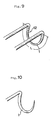
- Fig.9 and Fig.10 are perspective views of still other embodiments
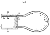
- Fig.8 is a vertical sectional view of another embodiment, wherein laser light is emitted through a light-transmissible ceramic material provided at the end of optical fiber
- Fig.11 is a plan view of a conventional apparatus.
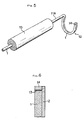
- Fig.1-Fig4 show the first embodiment.
- An optical fiber 1 is covered with a metal member, for example a stainless-steel tube 2.
- An instrument for excision 10 provides parallel holding portions 11A,11B and an open-loop portion 12 continuously connected with the holding portion 11A and the holding portion 11B.
- the open-loop portion 12 is projecting downward in the shape of letter U from the ends of the holding portions 11A,11B. Either side of optical fiber for example the other end of the optical fiber 1 covered with the holding portion 11A is optically connected with a laser light generator (not illustrated).
- a part of the open-loop portion 12 composes a laser light emitting portion L which is capable of emitting laser light in the direction C for excision the prominence M, and the rest part of the open-loop portion 12 composes a emission-intercepting portion in the opposite side to the direction C for excision in order to shut off the laser light emission.
- the open-loop portion 12 is formed as an uncovered portion by a stainless-steel tube 2 on the emitting portion L and the core of the optical fiber 1 is exposed at the uncovered portion so as to form the emitting portion L, and the rest part of open-loop portion 12 is covered with the stainless-steel tube 2 to form the laser light emission-intercepting portion in the present invention.
- a laser light generated from the light generator is transmitted into the optical fiber 1.
- laser light is so covered with the stainless-steel tube 2 that laser light is not emitted at the covered portion. Accordingly, a part of the stainless-steel tube 2 on the emitting portion L is so opened in the direction C for excision that a laser light is emitted from the exposed portion of the core of the optical fiber 1 in Fig.2.
- Laser light is irradiated to the prominence M, and excision is done from the root of the prominence M by the excision ability of laser light.
- An operator generally holds the instrument for excision in the present invention on the holding portion 11A, 11B, and then moves successiveively the instrument in the direction C for excision to exert excision.
- the core of the optical fiber 1 is directly covered with the stainless-steel tube 2, however the core of the optical fiber 1 may be covered with clad. Wherein the core of the optical fiber 1 needs to be exposed by removing of the clad on at least the emitting portion L.
- the angle ⁇ defined by the plane containing a straight portion 11A,11B of the holding portion and a plane containing the open-loop portion is 45-120°, preferably 65-85 ° .
- the parallel holding portion 11A,11B are formed to be hold, however only the holding portion 11A is formed and the emitting portion L is capable of being formed at the end of the holding portion 11A in Fig.5.
- the part designated by numeral 15 is a holder provided if needed for making easy to hold.
- a laser light reflecting portion 13 is provided at the end of the emitting portion L, wherein the reflecting portion 13 prevents laser light from being emitted at the end of the optical fiber 1 and laser light is capable of being emitted only at the side of the optical fiber 1.
- the reflecting portion 13 is providing a supporting member 14 continuously at the end of the stainless-steel tube 2 and the reflecting portion 13 is capable of being made of a reflecting material as a layer made by a gold plating positioned inside the supporting member 14.
- the emitting portion L is formed in U-shape in the above-described embodiments, when it is observed from the left side in Fig.2.
- it may be a circle or a trapezium or a rectangle (the top of every shape needs to remain discontinuous).
- Fig.7 shows a plan view of the third embodiment, and an open-loop porton 12A is formed at the end of a holder 20. A part of stainless-steel tube 2 is broken away and the core of the optical fiber 1 is exposed as shown in the first embodiment.
- the open-loop portion 12 is so positioned that the prominence is disposed within the open-loop portion 12A like a conventional snare, and then the open-loop portion 12A is moved in the direction C to exert excision by laser light irradiation.
- the holder 20 can be omitted.
- the emitting portion is formed on almost the whole of the open-loop portion 12 or 12A, however in the first embodiment the emitting portion can be formed only at the bottom of the U-shaped portion and in the third embodiment the emitting portion can be formed only on the right half of the open-loop portion.
- the core of the optical fiber is covered with a metal member for example stainless-steel tube from the point of view of strength.
- a light emitter can be formed of single optical fiber covered with a clad, wherein the clad is partly broken away and the core is exposed to form the emitting portion.
- the clad is equivalent to the light emission-intercepting portion in the present invention.
- an emitting member 31 made of a light-transmissible ceramic for example bent into ring-shape having circular cross section is provided at the end of an optical fiber 30 having a core 30a and a clad 30b, and laser light exited at the end of the core 30a of the optical fiber 30 enters into the emitting member 31, and then laser light is capable of being emitted from the emitting member 31.
- the part designated by numeral 32 is a holder and the part designated by numeral 33 is the instrument for connecting. Such method of the indirect incidence is applicable in the first embodiment and the second embodiment.
- the core 1 is to be so formed that its diameter of a circular cross-section gradually gets thinner from the holding portion (11a) onwards. Then the quantity of emitted laser light increases at the diminished portion as with the case of a slender conic probe, so the laser light can be led to the direction for excision more effectively.
- the surface of a laser light emitting portion can be provided with the surface layer for diffusing of laser light if needed.
- a laser light absorbing particle as carbon or a laser light diffusing particle as silica having larger refractive index than that of an emitting member as a core material can be utilized.
- the surface of a laser light emitting portion can be provided with a roughened surface to raise diffusing.
- a laser light emitter in the present invention is capable of being used in an operation by using endoscope as well as a surgical operation.
Abstract
Description
- This invention relates to a laser light emitter in use for excision of a prominence of living tissue of animal organisms.
- It is known that a high frequency scalpel is used in excision of a prominence of living tissue as a prostate. For example, a high frequency scalpel has a hexagonal wire 51 (in general, it is called snare) projecting in front of a
holder 50 as shown in Fig 11, and high frequency current is flown into thewire 51. - When such apparatus for excision is used, said
wire 51 is so positioned that a prominence is disposed within thewire 51 so as to cauterize to remove the prominence by heat. - However, this kind of a high frequency snare has a disadvantage fundamentally. Namely, when a prominence, that is an affected part, is removed under the presence of physiological salt solution, electricity flowing through physiological salt solution occasionally gives a shock to the human body or a burn near the affected part.
- So an operator cannot but substitute physiological salt solution by distilled water in medical treatment. And it is impossible to remove a prominence with stopping of bleeding.
- DE-A-28 21 376 teaches a laser light emitter for excision of a prominence of an animal organism comprising a holding portion and an excision means forming a transmission path for the laser light, wherein a part of said excision means comprises a laser light emitting portion formed as an uncovered,portion of said excision means, emitting laser light at least in the direction (C) of the holding portion, the remaining part of said excision means comprises a light emission-intercepting portion situated in the side opposite to said direction of the holding portion in order to shut off the laser light emission, and said laser light emitting portion is optically connected with a laser light generator.
- However, this prior art laser light emitter cannot exert a good excision under the presence of physiological salt solution and with a good control of bleeding.
- In order to solve above mentioned problems, the present invention relates to a laser light emitter of the above mentioned type, characterized by the fact that the uncovered portion is an elongated side portion along the length of the excision means.
- Moreover, in the prefered embodiment of the invention, said laser light emitter is made of an optical fiber covered with a metal member, the core of said optical fiber is exposed at said uncovered portion so as to form the laser emitting portion, and the remaining part of said excision means is covered with said metal member to form the laser light emission-intercepting portion.
- The other preferred embodiments are according to the dependent claims 3 to 9.
- Accordingly, safe excision of the prominence can be made without giving a shock to the human body or a burn, if laser light is emitted under the presence of physiological salt solution.
- In addition, it is possible to remove the prominence with control of bleeding by regulating quantity of laser light emission and the ability of hemostasis by laser light. Therefore a laser light emitter according to the present invention is so effective for excision of hemorrhagic organism.
- Fig.1 is a perspective view of the first embodiment of a laser light emitter according to the present invention; Fig.2 is a front view of the embodiment of Fig.1; Fig.3 is a sectional view of the embodiment of Fig.1 taken on line III - III; Fig.4 is a sectional view of the embodiment of Fig.1 taken on line IV - IV; Fig.5 is a perspective view of the second embodiment of a laser light emitter according to the present invention; Fig.6 is a vertical sectional view of a part of the second embodiment; Fig.7 is a plan view of the third embodiment of a laser light emitter according to the present invention; Fig.9 and Fig.10 are perspective views of still other embodiments; Fig.8 is a vertical sectional view of another embodiment, wherein laser light is emitted through a light-transmissible ceramic material provided at the end of optical fiber; Fig.11 is a plan view of a conventional apparatus.
- The present invention is described more particularly hereinafter.
- Fig.1-Fig4 show the first embodiment. An
optical fiber 1 is covered with a metal member, for example a stainless-steel tube 2. - An instrument for
excision 10 providesparallel holding portions loop portion 12 continuously connected with theholding portion 11A and theholding portion 11B. - The open-
loop portion 12 is projecting downward in the shape of letter U from the ends of theholding portions optical fiber 1 covered with theholding portion 11A is optically connected with a laser light generator (not illustrated). - On the other hand, a part of the open-
loop portion 12 composes a laser light emitting portion L which is capable of emitting laser light in the direction C for excision the prominence M, and the rest part of the open-loop portion 12 composes a emission-intercepting portion in the opposite side to the direction C for excision in order to shut off the laser light emission. - To be concrete, the open-
loop portion 12 is formed as an uncovered portion by a stainless-steel tube 2 on the emitting portion L and the core of theoptical fiber 1 is exposed at the uncovered portion so as to form the emitting portion L, and the rest part of open-loop portion 12 is covered with the stainless-steel tube 2 to form the laser light emission-intercepting portion in the present invention. - In such apparatus, a laser light generated from the light generator is transmitted into the
optical fiber 1. Wherein laser light is so covered with the stainless-steel tube 2 that laser light is not emitted at the covered portion. Accordingly, a part of the stainless-steel tube 2 on the emitting portion L is so opened in the direction C for excision that a laser light is emitted from the exposed portion of the core of theoptical fiber 1 in Fig.2. Laser light is irradiated to the prominence M, and excision is done from the root of the prominence M by the excision ability of laser light. An operator generally holds the instrument for excision in the present invention on theholding portion - In the above-described embodiment, the core of the
optical fiber 1 is directly covered with the stainless-steel tube 2, however the core of theoptical fiber 1 may be covered with clad. Wherein the core of theoptical fiber 1 needs to be exposed by removing of the clad on at least the emitting portion L. - In the first embodiment, the angle ϑ defined by the plane containing a
straight portion - In the first embodiment, the
parallel holding portion holding portion 11A is formed and the emitting portion L is capable of being formed at the end of theholding portion 11A in Fig.5. The part designated bynumeral 15 is a holder provided if needed for making easy to hold. - Moreover, according to the second embodiment in Fig.5 and Fig.6, a laser
light reflecting portion 13 is provided at the end of the emitting portion L, wherein the reflectingportion 13 prevents laser light from being emitted at the end of theoptical fiber 1 and laser light is capable of being emitted only at the side of theoptical fiber 1. The reflectingportion 13 is providing a supportingmember 14 continuously at the end of the stainless-steel tube 2 and the reflectingportion 13 is capable of being made of a reflecting material as a layer made by a gold plating positioned inside the supportingmember 14. - Further, the emitting portion L is formed in U-shape in the above-described embodiments, when it is observed from the left side in Fig.2. However it may be a circle or a trapezium or a rectangle (the top of every shape needs to remain discontinuous).
- On the other hand, Fig.7 shows a plan view of the third embodiment, and an open-
loop porton 12A is formed at the end of aholder 20. A part of stainless-steel tube 2 is broken away and the core of theoptical fiber 1 is exposed as shown in the first embodiment. - In the third embodiment, the open-
loop portion 12 is so positioned that the prominence is disposed within the open-loop portion 12A like a conventional snare, and then the open-loop portion 12A is moved in the direction C to exert excision by laser light irradiation. - In the third embodiment, the
holder 20 can be omitted. - On the other hand, in the above-described embodiments, the emitting portion is formed on almost the whole of the open-
loop portion - Moreover, in the above-described embodiments, the core of the optical fiber is covered with a metal member for example stainless-steel tube from the point of view of strength. However, if so much strength is not needed, a light emitter can be formed of single optical fiber covered with a clad, wherein the clad is partly broken away and the core is exposed to form the emitting portion. In this case, the clad is equivalent to the light emission-intercepting portion in the present invention.
- Moreover, in a modification of the third embodiment illustrated in Fig.8, an
emitting member 31 made of a light-transmissible ceramic for example bent into ring-shape having circular cross section is provided at the end of anoptical fiber 30 having acore 30a and a clad 30b, and laser light exited at the end of thecore 30a of theoptical fiber 30 enters into the emittingmember 31, and then laser light is capable of being emitted from the emittingmember 31. The part designated bynumeral 32 is a holder and the part designated bynumeral 33 is the instrument for connecting. Such method of the indirect incidence is applicable in the first embodiment and the second embodiment. - On the other hand, as shown in Fig.9 and Fig.10 respectively corresponding to Fig.1 and Fig.5, if laser light is wanted to be emitted more concentratedly to the direction for excision, the
core 1 is to be so formed that its diameter of a circular cross-section gradually gets thinner from the holding portion (11a) onwards. Then the quantity of emitted laser light increases at the diminished portion as with the case of a slender conic probe, so the laser light can be led to the direction for excision more effectively. - On the other hand, the surface of a laser light emitting portion can be provided with the surface layer for diffusing of laser light if needed. A laser light absorbing particle as carbon or a laser light diffusing particle as silica having larger refractive index than that of an emitting member as a core material can be utilized. And the surface of a laser light emitting portion can be provided with a roughened surface to raise diffusing.
- Moreover, a laser light emitter in the present invention is capable of being used in an operation by using endoscope as well as a surgical operation.
- As a result, according to the present invention, it is possible to remove the prominence under the presence of physiological salt solution with controlling bleeding without giving a shock to the human body.
Claims (9)
- A laser light emitter for excision of a prominence of an animal orqanism comprising a holdinq portion (11a) and an excision means (12) forming a transmission path for the laser light, wherein a part of said excision means comprises a laser light emitting portion (L,1;31) formed as an uncovered portion of said excision means, emitting laser light at least in the direction (C) of the holding portion, the remaining part of said excision means comprises a light emission-intercepting portion (2) in order to shut off the laser light emission, and said laser light emitting portion is optically connected with a laser light generator, characterized by the fact that the uncovered portion (1) is an elongated side portion along the length of the excision means.
- A laser light emitter according to claim 1, wherein said laser light emitter is made of an optical fiber (1) covered with a metal member (2), the core of said optical fiber (1) is exposed at said uncovered portion so as to form the laser emitting portion, and the remaining part of said excision means is covered with said metal member (2) to form the laser light emission-intercepting portion.
- A laser light emitter according to claim 1, wherein said laser light emitter includes at least one straight portion (11a) connected to an open-loop portion (12).
- A laser light emitter according to claim 3, wherein the open-loop portion (12) is situated in a plane defining an angle between 45° and 120° with a plane containing the straight portion (11a).
- A laser light emitter according to claim 1, wherein the excision means (12) is U-shaped.
- A laser light emitter according to claim 1, wherein the laser light emitting portion (1) has a circular cross-section of which the diameter gradually gets thinner from said holding portion (11a) onwards such that it concentrates light.
- A laser light emitter according to claim 1, wherein the laser light emitting portion comprises a light-transmission ceramic (31).
- A laser light emitter according to claim 1, wherein the laser light emitting portion comprises an optical fiber (1) covered with a clad.
- A laser light emitter according to claim 1, wherein a laser light reflecting portion (13) is provided at the end of the laser light emitting portion (1) for preventing laser light from being emitted at the end of the laser light emitting portion (1).
Applications Claiming Priority (3)
| Application Number | Priority Date | Filing Date | Title |
|---|---|---|---|
| JP1227092A JP3069108B2 (en) | 1989-09-01 | 1989-09-01 | Laser light emitting device |
| JP227092/89 | 1989-09-01 | ||
| PCT/JP1990/001108 WO1991003206A1 (en) | 1989-09-01 | 1990-08-30 | Device for radiating laser beams |
Publications (3)
| Publication Number | Publication Date |
|---|---|
| EP0441978A1 EP0441978A1 (en) | 1991-08-21 |
| EP0441978A4 EP0441978A4 (en) | 1992-04-22 |
| EP0441978B1 true EP0441978B1 (en) | 1994-06-15 |
Family
ID=16855367
Family Applications (1)
| Application Number | Title | Priority Date | Filing Date |
|---|---|---|---|
| EP90912952A Expired - Lifetime EP0441978B1 (en) | 1989-09-01 | 1990-08-30 | Device for radiating laser beams |
Country Status (11)
| Country | Link |
|---|---|
| US (1) | US5151097A (en) |
| EP (1) | EP0441978B1 (en) |
| JP (1) | JP3069108B2 (en) |
| CN (1) | CN1051667A (en) |
| AT (1) | ATE107153T1 (en) |
| AU (1) | AU6281890A (en) |
| CA (1) | CA2038949A1 (en) |
| DE (1) | DE69009976T2 (en) |
| ES (1) | ES2057586T3 (en) |
| WO (1) | WO1991003206A1 (en) |
| ZA (1) | ZA906920B (en) |
Families Citing this family (38)
| Publication number | Priority date | Publication date | Assignee | Title |
|---|---|---|---|---|
| US5195958A (en) * | 1990-05-25 | 1993-03-23 | Phillips Edward H | Tool for laparoscopic surgery |
| US5300063A (en) * | 1991-05-11 | 1994-04-05 | Nidek Co., Ltd. | Ophthalmic laser apparatus |
| DE59208936D1 (en) * | 1991-07-17 | 1997-11-06 | Siemens Ag | Handpiece for the stomatological application of laser light |
| US5688264A (en) * | 1992-10-19 | 1997-11-18 | The University Of Miami | Laser treatment for retinal detachment |
| US5342358A (en) * | 1993-01-12 | 1994-08-30 | S.L.T. Japan Co., Ltd. | Apparatus for operation by laser energy |
| US5451221A (en) * | 1993-12-27 | 1995-09-19 | Cynosure, Inc. | Endoscopic light delivery system |
| US5668993A (en) | 1994-02-28 | 1997-09-16 | Teleflex Information Systems, Inc. | Multithreaded batch processing system |
| US5476461A (en) * | 1994-05-13 | 1995-12-19 | Cynosure, Inc. | Endoscopic light delivery system |
| US6558375B1 (en) * | 2000-07-14 | 2003-05-06 | Cardiofocus, Inc. | Cardiac ablation instrument |
| US6270492B1 (en) | 1994-09-09 | 2001-08-07 | Cardiofocus, Inc. | Phototherapeutic apparatus with diffusive tip assembly |
| US5908415A (en) * | 1994-09-09 | 1999-06-01 | Rare Earth Medical, Inc. | Phototherapy methods and apparatus |
| US5632767A (en) * | 1994-09-09 | 1997-05-27 | Rare Earth Medical, Inc. | Loop diffusers for diffusion of optical radiation |
| US5637877A (en) * | 1995-06-06 | 1997-06-10 | Rare Earth Medical, Inc. | Ultraviolet sterilization of instrument lumens |
| US5947959A (en) * | 1994-09-09 | 1999-09-07 | Rare Earth Medical, Inc. | Phototherapeutic apparatus with diffusive tip assembly |
| US6676656B2 (en) * | 1994-09-09 | 2004-01-13 | Cardiofocus, Inc. | Surgical ablation with radiant energy |
| US8025661B2 (en) | 1994-09-09 | 2011-09-27 | Cardiofocus, Inc. | Coaxial catheter instruments for ablation with radiant energy |
| US6423055B1 (en) | 1999-07-14 | 2002-07-23 | Cardiofocus, Inc. | Phototherapeutic wave guide apparatus |
| US6579285B2 (en) * | 1994-09-09 | 2003-06-17 | Cardiofocus, Inc. | Photoablation with infrared radiation |
| US8540704B2 (en) | 1999-07-14 | 2013-09-24 | Cardiofocus, Inc. | Guided cardiac ablation catheters |
| US7935108B2 (en) | 1999-07-14 | 2011-05-03 | Cardiofocus, Inc. | Deflectable sheath catheters |
| US9033961B2 (en) | 1999-07-14 | 2015-05-19 | Cardiofocus, Inc. | Cardiac ablation catheters for forming overlapping lesions |
| US8900219B2 (en) | 1999-07-14 | 2014-12-02 | Cardiofocus, Inc. | System and method for visualizing tissue during ablation procedures |
| US20040147911A1 (en) * | 1999-08-25 | 2004-07-29 | Cardiofocus, Inc. | Surgical ablation instruments for forming an encircling lesion |
| US20040167503A1 (en) * | 1999-08-25 | 2004-08-26 | Cardiofocus, Inc. | Malleable surgical ablation instruments |
| WO2004000098A2 (en) | 2002-06-19 | 2003-12-31 | Palomar Medical Technologies, Inc. | Method and apparatus for treatment of cutaneous and subcutaneous conditions |
| US7731715B2 (en) * | 2004-12-10 | 2010-06-08 | Edwards Lifesciences Corporation | Ablative treatment of atrial fibrillation via the coronary sinus |
| US20060253025A1 (en) * | 2005-04-21 | 2006-11-09 | Kaufman Jonathan J | Ultrasonic Bone Assessment Apparatus and Method |
| US7856985B2 (en) | 2005-04-22 | 2010-12-28 | Cynosure, Inc. | Method of treatment body tissue using a non-uniform laser beam |
| DE102006016957B4 (en) * | 2006-04-11 | 2010-04-22 | Vimecon Gmbh | laser applicator |
| US7586957B2 (en) | 2006-08-02 | 2009-09-08 | Cynosure, Inc | Picosecond laser apparatus and methods for its operation and use |
| US8696653B2 (en) | 2009-10-02 | 2014-04-15 | Cardiofocus, Inc. | Cardiac ablation system with pulsed aiming light |
| EP2485671B1 (en) | 2009-10-06 | 2019-03-20 | Cardiofocus, Inc. | Cardiac ablation image analysis system |
| JP2015510142A (en) * | 2012-01-31 | 2015-04-02 | アシメトリック メディカル リミテッド | Optical fiber configured to emit radiation by bending |
| KR102342629B1 (en) | 2012-04-18 | 2021-12-22 | 싸이노슈어, 엘엘씨 | Picosecond laser apparatus and methods for treating target tissues with same |
| US10285757B2 (en) | 2013-03-15 | 2019-05-14 | Cynosure, Llc | Picosecond optical radiation systems and methods of use |
| EP3137007A4 (en) | 2014-04-28 | 2017-09-27 | Cardiofocus, Inc. | System and method for visualizing tissue with an icg dye composition during ablation procedures |
| EP3226744A4 (en) | 2014-12-03 | 2018-08-08 | Cardiofocus, Inc. | System and method for visual confirmation of pulmonary vein isolation during ablation procedures |
| KR102627248B1 (en) | 2018-02-26 | 2024-01-19 | 싸이노슈어, 엘엘씨 | Q-switched cavity dumping subnanosecond laser |
Citations (1)
| Publication number | Priority date | Publication date | Assignee | Title |
|---|---|---|---|---|
| DE2821376A1 (en) * | 1977-05-16 | 1978-11-23 | Olympus Optical Co | Laser scalpel cauterising inside somatic cavity - has tubular member containing beam transmitter emitter and receiver |
Family Cites Families (12)
| Publication number | Priority date | Publication date | Assignee | Title |
|---|---|---|---|---|
| US4126136A (en) * | 1976-02-09 | 1978-11-21 | Research Corporation | Photocoagulating scalpel system |
| JPS5710648Y2 (en) * | 1977-06-24 | 1982-03-02 | ||
| US4266547A (en) * | 1977-05-16 | 1981-05-12 | Olympus Optical Co., Ltd. | Laser knife |
| US4240431A (en) * | 1977-05-16 | 1980-12-23 | Olympus Optical Co., Ltd. | Laser knife |
| US4249533A (en) * | 1977-05-16 | 1981-02-10 | Olympus Optical Co., Ltd. | Laser knife |
| US4273127A (en) * | 1978-10-12 | 1981-06-16 | Research Corporation | Method for cutting and coagulating tissue |
| JPS5810039A (en) * | 1981-07-13 | 1983-01-20 | 住友電気工業株式会社 | Handpiece for laser knife |
| US4693244A (en) * | 1984-05-22 | 1987-09-15 | Surgical Laser Technologies, Inc. | Medical and surgical laser probe I |
| US4736743A (en) * | 1986-05-12 | 1988-04-12 | Surgical Laser Technology, Inc. | Vaporization contact laser probe |
| JPS62202815U (en) * | 1986-06-13 | 1987-12-24 | ||
| JPS63216579A (en) * | 1987-03-05 | 1988-09-08 | 大工園 則雄 | Laser beam irradiation apparatus for hyperthermia |
| JP2671016B2 (en) * | 1988-07-08 | 1997-10-29 | サージカル・レーザー・テクノロジーズ・インコーポレイテッド | Laser treatment device for narrow path in living tissue |
-
1989
- 1989-09-01 JP JP1227092A patent/JP3069108B2/en not_active Expired - Lifetime
-
1990
- 1990-08-28 US US07/573,563 patent/US5151097A/en not_active Expired - Fee Related
- 1990-08-30 DE DE69009976T patent/DE69009976T2/en not_active Expired - Fee Related
- 1990-08-30 ZA ZA906920A patent/ZA906920B/en unknown
- 1990-08-30 EP EP90912952A patent/EP0441978B1/en not_active Expired - Lifetime
- 1990-08-30 WO PCT/JP1990/001108 patent/WO1991003206A1/en active IP Right Grant
- 1990-08-30 CA CA002038949A patent/CA2038949A1/en not_active Abandoned
- 1990-08-30 AT AT90912952T patent/ATE107153T1/en not_active IP Right Cessation
- 1990-08-30 ES ES90912952T patent/ES2057586T3/en not_active Expired - Lifetime
- 1990-08-30 AU AU62818/90A patent/AU6281890A/en not_active Abandoned
- 1990-08-31 CN CN90108169A patent/CN1051667A/en active Pending
Patent Citations (1)
| Publication number | Priority date | Publication date | Assignee | Title |
|---|---|---|---|---|
| DE2821376A1 (en) * | 1977-05-16 | 1978-11-23 | Olympus Optical Co | Laser scalpel cauterising inside somatic cavity - has tubular member containing beam transmitter emitter and receiver |
Also Published As
| Publication number | Publication date |
|---|---|
| DE69009976T2 (en) | 1995-03-02 |
| JPH0390143A (en) | 1991-04-16 |
| EP0441978A4 (en) | 1992-04-22 |
| AU6281890A (en) | 1991-04-08 |
| CN1051667A (en) | 1991-05-29 |
| ES2057586T3 (en) | 1994-10-16 |
| US5151097A (en) | 1992-09-29 |
| WO1991003206A1 (en) | 1991-03-21 |
| DE69009976D1 (en) | 1994-07-21 |
| JP3069108B2 (en) | 2000-07-24 |
| ATE107153T1 (en) | 1994-07-15 |
| CA2038949A1 (en) | 1991-03-02 |
| ZA906920B (en) | 1991-06-26 |
| EP0441978A1 (en) | 1991-08-21 |
Similar Documents
| Publication | Publication Date | Title |
|---|---|---|
| EP0441978B1 (en) | Device for radiating laser beams | |
| JP3148216B2 (en) | Treatment equipment by laser beam irradiation | |
| JP2779825B2 (en) | Laser light emitting device | |
| US4273127A (en) | Method for cutting and coagulating tissue | |
| EP0637942B1 (en) | Medical device | |
| JP2882814B2 (en) | Laser irradiation equipment | |
| US4517974A (en) | Disposable hand piece for surgical lasers | |
| KR920700717A (en) | Laser light irradiation device | |
| JP3145379B2 (en) | Laser light guide probe | |
| WO1991003275A1 (en) | Device for irradiating laser beams | |
| US20020183728A1 (en) | Laser probe | |
| US6673065B1 (en) | Slender tip laser scalpel | |
| JPH067835B2 (en) | Internal and surgical laser probe | |
| JP2683565B2 (en) | Laser light transmitting body and method of manufacturing the same | |
| RU2038106C1 (en) | Emitting laser device to be used in medical treatment | |
| JP3813760B2 (en) | Medical or dental light irradiation chip and laser irradiation apparatus | |
| JP3749052B2 (en) | Contact light irradiation chip, handpiece, and laser irradiation apparatus | |
| JPH0542165A (en) | Catheter for incision of valve ring | |
| CN114404037A (en) | Laser therapeutic equipment | |
| JPH05212050A (en) | Laser probe | |
| JPH03234253A (en) | Laser probe device | |
| JPH0299048A (en) | Laser knife for endoscope | |
| JPS61244342A (en) | Laser irradiation apparatus | |
| JPS63147452A (en) | Fiber therapeutic instrument | |
| JPH0595954A (en) | Laser probe |
Legal Events
| Date | Code | Title | Description |
|---|---|---|---|
| PUAI | Public reference made under article 153(3) epc to a published international application that has entered the european phase |
Free format text: ORIGINAL CODE: 0009012 |
|
| 17P | Request for examination filed |
Effective date: 19910515 |
|
| AK | Designated contracting states |
Kind code of ref document: A1 Designated state(s): AT CH DE ES FR GB IT LI NL SE |
|
| A4 | Supplementary search report drawn up and despatched |
Effective date: 19920303 |
|
| AK | Designated contracting states |
Kind code of ref document: A4 Designated state(s): AT CH DE ES FR GB IT LI NL SE |
|
| 17Q | First examination report despatched |
Effective date: 19930115 |
|
| GRAA | (expected) grant |
Free format text: ORIGINAL CODE: 0009210 |
|
| AK | Designated contracting states |
Kind code of ref document: B1 Designated state(s): AT CH DE ES FR GB IT LI NL SE |
|
| REF | Corresponds to: |
Ref document number: 107153 Country of ref document: AT Date of ref document: 19940715 Kind code of ref document: T |
|
| REF | Corresponds to: |
Ref document number: 69009976 Country of ref document: DE Date of ref document: 19940721 |
|
| ITF | It: translation for a ep patent filed |
Owner name: STUDIO TORTA SOCIETA' SEMPLICE |
|
| ET | Fr: translation filed | ||
| REG | Reference to a national code |
Ref country code: ES Ref legal event code: FG2A Ref document number: 2057586 Country of ref document: ES Kind code of ref document: T3 |
|
| EAL | Se: european patent in force in sweden |
Ref document number: 90912952.0 |
|
| PLBE | No opposition filed within time limit |
Free format text: ORIGINAL CODE: 0009261 |
|
| STAA | Information on the status of an ep patent application or granted ep patent |
Free format text: STATUS: NO OPPOSITION FILED WITHIN TIME LIMIT |
|
| 26N | No opposition filed | ||
| PGFP | Annual fee paid to national office [announced via postgrant information from national office to epo] |
Ref country code: AT Payment date: 20000817 Year of fee payment: 11 |
|
| PGFP | Annual fee paid to national office [announced via postgrant information from national office to epo] |
Ref country code: SE Payment date: 20000821 Year of fee payment: 11 |
|
| PGFP | Annual fee paid to national office [announced via postgrant information from national office to epo] |
Ref country code: GB Payment date: 20000823 Year of fee payment: 11 |
|
| PGFP | Annual fee paid to national office [announced via postgrant information from national office to epo] |
Ref country code: NL Payment date: 20000824 Year of fee payment: 11 |
|
| PGFP | Annual fee paid to national office [announced via postgrant information from national office to epo] |
Ref country code: DE Payment date: 20000828 Year of fee payment: 11 |
|
| PGFP | Annual fee paid to national office [announced via postgrant information from national office to epo] |
Ref country code: FR Payment date: 20000829 Year of fee payment: 11 |
|
| PGFP | Annual fee paid to national office [announced via postgrant information from national office to epo] |
Ref country code: ES Payment date: 20000919 Year of fee payment: 11 Ref country code: CH Payment date: 20000919 Year of fee payment: 11 |
|
| PG25 | Lapsed in a contracting state [announced via postgrant information from national office to epo] |
Ref country code: GB Free format text: LAPSE BECAUSE OF NON-PAYMENT OF DUE FEES Effective date: 20010830 Ref country code: AT Free format text: LAPSE BECAUSE OF NON-PAYMENT OF DUE FEES Effective date: 20010830 |
|
| PG25 | Lapsed in a contracting state [announced via postgrant information from national office to epo] |
Ref country code: SE Free format text: LAPSE BECAUSE OF NON-PAYMENT OF DUE FEES Effective date: 20010831 Ref country code: LI Free format text: LAPSE BECAUSE OF NON-PAYMENT OF DUE FEES Effective date: 20010831 Ref country code: ES Free format text: LAPSE BECAUSE OF NON-PAYMENT OF DUE FEES Effective date: 20010831 Ref country code: CH Free format text: LAPSE BECAUSE OF NON-PAYMENT OF DUE FEES Effective date: 20010831 |
|
| PG25 | Lapsed in a contracting state [announced via postgrant information from national office to epo] |
Ref country code: NL Free format text: LAPSE BECAUSE OF NON-PAYMENT OF DUE FEES Effective date: 20020301 |
|
| EUG | Se: european patent has lapsed |
Ref document number: 90912952.0 |
|
| REG | Reference to a national code |
Ref country code: CH Ref legal event code: PL |
|
| PG25 | Lapsed in a contracting state [announced via postgrant information from national office to epo] |
Ref country code: FR Free format text: LAPSE BECAUSE OF NON-PAYMENT OF DUE FEES Effective date: 20020430 |
|
| NLV4 | Nl: lapsed or anulled due to non-payment of the annual fee |
Effective date: 20020301 |
|
| PG25 | Lapsed in a contracting state [announced via postgrant information from national office to epo] |
Ref country code: DE Free format text: LAPSE BECAUSE OF NON-PAYMENT OF DUE FEES Effective date: 20020501 |
|
| REG | Reference to a national code |
Ref country code: FR Ref legal event code: ST |
|
| REG | Reference to a national code |
Ref country code: ES Ref legal event code: FD2A Effective date: 20020911 |
|
| PG25 | Lapsed in a contracting state [announced via postgrant information from national office to epo] |
Ref country code: IT Free format text: LAPSE BECAUSE OF NON-PAYMENT OF DUE FEES;WARNING: LAPSES OF ITALIAN PATENTS WITH EFFECTIVE DATE BEFORE 2007 MAY HAVE OCCURRED AT ANY TIME BEFORE 2007. THE CORRECT EFFECTIVE DATE MAY BE DIFFERENT FROM THE ONE RECORDED. Effective date: 20050830 |