EP0445017A1 - Coaxial resonator with distributed tuning capacity - Google Patents
Coaxial resonator with distributed tuning capacity Download PDFInfo
- Publication number
- EP0445017A1 EP0445017A1 EP91400505A EP91400505A EP0445017A1 EP 0445017 A1 EP0445017 A1 EP 0445017A1 EP 91400505 A EP91400505 A EP 91400505A EP 91400505 A EP91400505 A EP 91400505A EP 0445017 A1 EP0445017 A1 EP 0445017A1
- Authority
- EP
- European Patent Office
- Prior art keywords
- resonator
- conductive layer
- capacitor
- conductor
- conductive
- Prior art date
- Legal status (The legal status is an assumption and is not a legal conclusion. Google has not performed a legal analysis and makes no representation as to the accuracy of the status listed.)
- Granted
Links
Images


Classifications
-
- H—ELECTRICITY
- H01—ELECTRIC ELEMENTS
- H01P—WAVEGUIDES; RESONATORS, LINES, OR OTHER DEVICES OF THE WAVEGUIDE TYPE
- H01P7/00—Resonators of the waveguide type
- H01P7/04—Coaxial resonators
-
- G—PHYSICS
- G01—MEASURING; TESTING
- G01R—MEASURING ELECTRIC VARIABLES; MEASURING MAGNETIC VARIABLES
- G01R33/00—Arrangements or instruments for measuring magnetic variables
- G01R33/20—Arrangements or instruments for measuring magnetic variables involving magnetic resonance
- G01R33/24—Arrangements or instruments for measuring magnetic variables involving magnetic resonance for measuring direction or magnitude of magnetic fields or magnetic flux
-
- G—PHYSICS
- G01—MEASURING; TESTING
- G01R—MEASURING ELECTRIC VARIABLES; MEASURING MAGNETIC VARIABLES
- G01R33/00—Arrangements or instruments for measuring magnetic variables
- G01R33/20—Arrangements or instruments for measuring magnetic variables involving magnetic resonance
- G01R33/28—Details of apparatus provided for in groups G01R33/44 - G01R33/64
- G01R33/32—Excitation or detection systems, e.g. using radio frequency signals
- G01R33/34—Constructional details, e.g. resonators, specially adapted to MR
- G01R33/343—Constructional details, e.g. resonators, specially adapted to MR of slotted-tube or loop-gap type
-
- G—PHYSICS
- G01—MEASURING; TESTING
- G01R—MEASURING ELECTRIC VARIABLES; MEASURING MAGNETIC VARIABLES
- G01R33/00—Arrangements or instruments for measuring magnetic variables
- G01R33/20—Arrangements or instruments for measuring magnetic variables involving magnetic resonance
- G01R33/28—Details of apparatus provided for in groups G01R33/44 - G01R33/64
- G01R33/32—Excitation or detection systems, e.g. using radio frequency signals
- G01R33/36—Electrical details, e.g. matching or coupling of the coil to the receiver
- G01R33/3628—Tuning/matching of the transmit/receive coil
Definitions
- the present invention relates to a coaxial resonator with distributed tuning capacity.
- a resonator can be used in the probes of nuclear magnetic resonance magnetometers (NMR for short).
- NMR nuclear magnetic resonance magnetometers
- One of the fields of application of the invention is therefore the measurement of magnetic fields, in particular of the earth's magnetic field.
- the resonator of the invention can be used in other devices.
- the resonator of the invention When used in an NMR probe, the resonator of the invention is used as described in particular in French patent applications FR-A-1 447 226 and FR-A-2 098 624. It does not therefore is not useful to describe in detail this device. It suffices to recall that the probe comprises one or more bottles containing a liquid sample (also called “radical solution"), these bottles being placed in a coaxial resonator.
- This resonator consists of a central conductor passing through the bottle (s) and an external conductor located around the bottle (s).
- the probe includes windings for sampling and reinjection of a signal at the LARMOR frequency. This frequency is defined by the magnetic field in which the probe is bathed and by the gyromagnetic ratio specific to the liquid sample used.
- This resonator is powered by a coaxial cable 30, having a central core 32 and an outer conductive sheath 34 such as a braid; the sheath is connected to the outer conductor 20 and the core 32 to the second end 14 of the central conductor by an extension 36; moreover, this end 14 is in turn connected to the braid by a loop 38, generally constituted by a silver wire.
- This resonator operates in the following manner.
- the radiofrequency energy is supplied by the coaxial cable 30.
- the resonance frequency is adjusted by the capacitors 24.
- the central conductor 10 constitutes a "hot” point (from the point of view of potential) and the external conductor 20 a “cold” point ".
- the impedance matching between the coaxial cable (whose impedance is generally 50 Ohms) and the resonator is obtained by loop 38, which behaves like an adjustable inductance arranged in short circuit at the end of the cable coaxial.
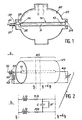
- FIG. 2 The equivalent electrical diagram of the assembly is shown in Figure 2 attached.
- This diagram shows, on part (a), a resonator 40 with an adaptation loop 42 and a tuning capacitor 44.
- the resonator 40 has impedances distributed along the z axis. This means that between dimension z and dimension z + dz, an elementary section of the resonator is equivalent to the circuit of part (b), with two inductances L / 2, two resistors R / 2, a capacitor C with a resistance R ′
- the values L, C and R, R ′ being functions of the geometry of the resonator (therefore of z) as well as of the dielectric elements which it contains.
- the object of the present invention is precisely to remedy all these drawbacks. To this end, it offers a resonator in which the adjustment capacity is distributed all along the resonator, that is to say in practice, either along the central conductor, as it seems most advantageous, or along of the external conductor.
- this distributed capacity is obtained by two (or possibly three) cylindrical armatures of the same axis as the axis of the resonator, nested one inside the other, one of the armatures constituting one of the conductors of the resonator.
- These reinforcements can be obtained by depositing a conductive layer on an insulating tube.
- the subject of the present invention is a coaxial resonator comprising an external conductor and a central conductor both having a symmetry of revolution about the same axis, and at least one tuning capacitor, this resonator being characterized by the fact that the tuning capacitor is distributed along the axis of the resonator and comprises at least two cylindrical armatures, nested one inside the other, and having as axis that of the resonator, one of the two armatures constituting one of the two conductors of the resonator.
- the capacitor is distributed along the central conductor of the resonator, one of the reinforcements of the capacitor constituting this central conductor.
- the capacitor comprises a first armature constituted by a first insulating tube covered externally with a first conductive layer and a second armature comprising a second insulating tube fitted in the first and externally covered with a second conductive layer, one of the tubes being able to be moved, for example manually relative to the other.
- the capacitor further comprises a third frame constituted by an insulating core covered with a third conductive layer, this core being fitted into the second tube.
- the capacitor is distributed along the outside conductor of the resonator, one of the reinforcements of the capacitor constituting this outside conductor.
- the core 62 is fitted into the tube 56, which is fitted into the tube 50.
- a double capacitor is thus obtained with three armatures, the central armature being constituted by the conductor 58 on the tube 56.
- the insulating tubes can be made of quartz, pyrex, macor (brands deposited), etc ... Their machining is assured to the hundredth of a millimeter. They can also be made of porcelain by molding.
- the conductive layers can be obtained by depositing silver paint directly spread on the outside surface of the tubes and on the central core, and by annealing at around 550 ° C.
- the thickness of the conductive layer is approximately 2/100 mm.
- a flat insulator for example in mica
- first tube 50 with an outside diameter of 18 mm, an inside diameter of 16 mm and a length of 105 mm, with 6 to 8 conductive strips spaced one millimeter apart.
- the second tube 56 can have an outside diameter of 15.9 mm, an inside diameter of 13.9 mm and a length of 102 mm with a space of one millimeter interrupting the conductive layer.
- the core 62 can have a diameter of 13.8 mm and a length of 102 mm. It can include 6 or 8 strips spaced 1 mm each. By sliding in the tube 56, it makes it possible to adjust the value of the total capacity.
- Each of the eight bands 52 is connected to one of the eight bands 64 and to one of the eight sectors 53 of the external conductor.
- the conductor 58 of the central tube is not connected to the external conductor but to the core of the coaxial supply cable (which will appear better in FIG. 7).
- the interconnection mode is then modified as indicated in FIG. 6. Seven of the sectors 53 are connected to the seven strips 52 of the outer tube and the eighth is connected to the single conductor 72 of the core.
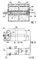
- Figure 7 shows, in section, a coaxial resonator equipped with a capacitor distributed along the central conductor.
- the central conductor 10 is constituted by one of the armatures nested one inside the other, ie 80, 82, 84 and preferably by 82.
- the armatures 80 and 84 are connected to the external conductor 20 as illustrated in FIGS. 4 and 6 already described and the central frame 82 is connected to the core of the power cable 30, the adaptation always taking place by a loop.
- the adjustment of the total capacity can be carried out by adjusting the depression of the core, for example by rotation by means of a screwdriver 90 if a thread has been provided between the core and the frame 82 in which it is fitted. .
- part (a) the resonator 100 with a central conductor 10, an external conductor 20.
- This resonator is connected to an adaptation inductor 42.
- the diagram is the same in figure 2 part (a). But unlike the prior art, there is no longer an adjustable capacitor at the end of the resonator such as 44 in FIG. 2, but a capacitor distributed all along the central conductor (armatures 101 and 102).
- Part (b) of FIG. 8 shows the equivalent electrical diagram of an elementary section of this resonator between the dimensions z and z + dz.
- Figures 9 to 13 show other embodiments of the resonator of the invention.
- FIG. 9 first of all, we see (part a) an insulating tube 110 covered externally with a conductive layer 112 and internally with a conductive layer 111, both in the form of strips. Agreement is obtained by introducing a core 113 internally covered with a conductive layer 114.
- the outer tube does not have the same thickness over its entire length, so that the distributed capacity varies along the axis of the resonator.
- part a the tube 120 is thicker in the middle than at its ends while, in FIG. 11, part a, the tube 130 is thinner in the middle than at its ends.
- an inner tube 121 and 131 respectively is provided (constituting for example the central conductor).
- Figure 12 shows two variants where the outer conductive layer has the form of wide helical bands 140 (part a) or narrow 141 (part b).
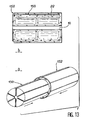
- FIG 13 shows an embodiment where the adjustment capacitor is arranged outside the resonator.
- This capacitor comprises, for example, two tubes 150 and 152 fitted one inside the other and covered with conductive strips (the central conductor 10 being constituted in a conventional manner).
Abstract
Ce résonateur comprend un conducteur extérieur (20) et un conducteur central (10) ayant tous deux une symétrie de révolution autour d'un même axe (A). Le condensateur d'accord est réparti tout le long de l'axe du résonateur et comprend au moins deux armatures cylindriques (80, 82, 84) emboitées l'une dans l'autre, et ayant comme axe celui (A) du résonateur, l'une des deux armatures (82) constituant l'un des deux conducteurs du résonateur. Application, notamment, aux sondes pour magnétomètres à RMN. <IMAGE>This resonator comprises an external conductor (20) and a central conductor (10) both having a symmetry of revolution about the same axis (A). The tuning capacitor is distributed along the axis of the resonator and comprises at least two cylindrical armatures (80, 82, 84) nested one inside the other, and having as axis that (A) of the resonator, one of the two armatures (82) constituting one of the two conductors of the resonator. Application, in particular, to probes for NMR magnetometers. <IMAGE>
Description
La présente invention a pour objet un résonateur coaxial à capacité d'accord répartie. Un tel résonateur peut être utilisé dans les sondes de magnétomètres à résonance magnétique nucléaire (RMN en abrégé). Un des domaines d'application de l'invention est donc la mesure des champs magnétiques, notamment du champ magnétique terrestre. Mais le résonateur de l'invention peut être utilisé dans d'autres appareils.The present invention relates to a coaxial resonator with distributed tuning capacity. Such a resonator can be used in the probes of nuclear magnetic resonance magnetometers (NMR for short). One of the fields of application of the invention is therefore the measurement of magnetic fields, in particular of the earth's magnetic field. However, the resonator of the invention can be used in other devices.
Lorsqu'il est utilisé dans une sonde à RMN, le résonateur de l'invention l'est de la manière décrite notamment dans les demandes de brevets français FR-A-1 447 226 et FR-A-2 098 624. Il n'est donc pas utile de décrire en détail cet appareil. Il suffit de rappeler que la sonde comprend un ou plusieurs flacons contenant un échantillon liquide (dit aussi "solution radicalaire"), ces flacons étant disposés dans un résonateur coaxial. Ce résonateur est constitué d'un conducteur central traversant le ou les flacon(s) et un conducteur extérieur situé autour du ou des flacon(s). La sonde comprend des enroulements de prélèvement et de réinjection d'un signal à la fréquence de LARMOR. Cette fréquence est définie, par le champ magnétique dans lequel baigne la sonde et par le rapport gyromagnétique propre à l'échantillon liquide utilisé.When used in an NMR probe, the resonator of the invention is used as described in particular in French patent applications FR-A-1 447 226 and FR-A-2 098 624. It does not therefore is not useful to describe in detail this device. It suffices to recall that the probe comprises one or more bottles containing a liquid sample (also called "radical solution"), these bottles being placed in a coaxial resonator. This resonator consists of a central conductor passing through the bottle (s) and an external conductor located around the bottle (s). The probe includes windings for sampling and reinjection of a signal at the LARMOR frequency. This frequency is defined by the magnetic field in which the probe is bathed and by the gyromagnetic ratio specific to the liquid sample used.
Un résonateur pour sonde RMN selon l'art antérieur est représenté sur la figure 1 annexée. Tel que représenté, il comprend :
- un conducteur central 10 ayant la forme d'un cylindre circulaire d'axe A, avec une
première extrémité 12 et uneseconde extrémité 14 ; - un conducteur extérieur 20, de révolution autour de l'axe A et constitué par une couche conductrice déposée sur la paroi extérieure des
flacons 22 contenant la solution radicalaire, la couche conductrice étant généralement divisée en secteurs ; - des condensateurs d'accord 24, connectés entre la
première extrémité 12 du conducteur central 10 et le conducteur extérieur 20.
- a
central conductor 10 having the shape of a circular cylinder of axis A, with afirst end 12 and asecond end 14; - an
outer conductor 20, of revolution about the axis A and consisting of a conductive layer deposited on the outer wall of thebottles 22 containing the radical solution, the conductive layer being generally divided into sectors; -
tuning capacitors 24, connected between thefirst end 12 of thecentral conductor 10 and theexternal conductor 20.
Ce résonateur est alimenté par un câble coaxial 30, ayant une âme centrale 32 et une gaine conductrice extérieure 34 telle qu'une tresse ; la gaine est reliée au conducteur extérieur 20 et l'âme 32 à la seconde extrémité 14 du conducteur central par un prolongement 36 ; par ailleurs, cette extrémité 14 est reliée à son tour à la tresse par une boucle 38, généralement constituée par un fil d'argent.This resonator is powered by a
Ce résonateur fonctionne de la manière suivante. L'énergie radiofréquence est apportée par le câble coaxial 30. La fréquence de résonance est ajustée par les condensateurs 24. Le conducteur central 10 constitue un point "chaud" (du point de vue du potentiel) et le conducteur extérieur 20 un point "froid". L'adaptation d'impédance entre le câble coaxial (dont l'impédance est en général de 50 Ohms) et le résonateur est obtenu par la boucle 38, qui se comporte comme une inductance réglable disposée en court-circuit à l'extrémité du câble coaxial.This resonator operates in the following manner. The radiofrequency energy is supplied by the
Le schéma électrique équivalent de l'ensemble est représenté sur la figure 2 annexée. Ce schéma montre, sur la partie (a), un résonateur 40 avec une boucle d'adaptation 42 et un condensateur d'accord 44. Le résonateur 40 est à impédances réparties selon l'axe z. Cela signifie qu'entre la cote z et la cote z+dz, une tranche élémentaire du résonateur équivaut au circuit de la partie (b), avec deux inductances L/2, deux résistances R/2, un condensateur C avec une résistance R′ en parallèle, les valeurs L, C et R, R′ étant fonctions de la géométrie du résonateur (donc de z) ainsi que des éléments diélectriques qu'il contient.The equivalent electrical diagram of the assembly is shown in Figure 2 attached. This diagram shows, on part (a), a
Bien que donnant satisfaction à certains égards, de tels résonateurs présentent des inconvénients, essentiellement liés à la présence du ou des condensateurs de réglage (24 sur la figure 1 et 44 sur le schéma de la figure 2a). Ces inconvénients sont les suivants :
- il est difficile de trouver des condensateurs offrant toutes les conditions requises dans cette application : bonne qualité en haute fréquence, absence d'effet redresseur, bonne tenue en tension, amagnétisme, facilité de réglage, etc... ;
- on observe un fort rayonnement à très haute fréquence au niveau des condensateurs, sauf à blinder ceux-ci ;
- la bulle de dilatation, qui est inévitablement présente dans les flacons, peut venir se placer au niveau des condensateurs de réglage et désaccorder le résonateur ;
- les différences (de l'ordre de ± 10%) entre les capacités des différents condensateurs d'accord entraînent des différences d'intensité dans les courants circulant dans les secteurs du conducteur extérieur auxquels ils sont reliés et, par conséquent, des pertes par rayonnement.
- it is difficult to find capacitors offering all the conditions required in this application: good quality at high frequency, absence of rectifier effect, good voltage resistance, non-magnetism, ease of adjustment, etc ...;
- there is strong radiation at very high frequency at the capacitors, except to shield them;
- the expansion bubble, which is inevitably present in the bottles, can be placed at the level of the adjustment capacitors and detune the resonator;
- the differences (of the order of ± 10%) between the capacities of the different tuning capacitors lead to differences in intensity in the currents flowing in the sectors of the external conductor to which they are connected and, consequently, in radiation losses .
La présente invention a justement pour but de remédier à tous ces inconvénients. A cette fin, elle propose un résonateur dans lequel la capacité de réglage se trouve répartie tout le long du résonateur, c'est-à-dire en pratique, soit le long du conducteur central, comme cela semble le plus avantageux, soit le long du conducteur extérieur.The object of the present invention is precisely to remedy all these drawbacks. To this end, it offers a resonator in which the adjustment capacity is distributed all along the resonator, that is to say in practice, either along the central conductor, as it seems most advantageous, or along of the external conductor.
De préférence, cette capacité répartie est obtenue par deux (ou éventuellement trois) armatures cylindriques de même axe que l'axe du résonateur, emboîtées l'une dans l'autre, l'une des armatures constituant l'un des conducteurs du résonateur.Preferably, this distributed capacity is obtained by two (or possibly three) cylindrical armatures of the same axis as the axis of the resonator, nested one inside the other, one of the armatures constituting one of the conductors of the resonator.
Ces armatures peuvent être obtenues par dépôt d'une couche conductrice sur un tube isolant.These reinforcements can be obtained by depositing a conductive layer on an insulating tube.
Tous les inconvénients énumérés plus haut se trouvent alors éliminés :
- la réalisation d'excellents résonateurs (qualité en haute fréquence, absence d'effet redresseur, bonne tenue en tension, amagnétisme) est simple ; quant au réglage, il s'obtient simplement en faisant glisser l'une des armatures par rapport à l'autre ;
- le rayonnement en bout de résonateur est supprimé ;
- le désaccord dû au déplacement de la bulle de dilatation est évité puisque la bulle affecte la valeur de la capacité d'une manière indépendante de sa position ;
- l'égalité (à 0,5% près) entre les différentes capacités partielles de la capacité repartie assure la symétrie des courants circulant dans les secteurs du conducteur extérieur et, par conséquent, l'absence de rayonnement.
- the production of excellent resonators (high frequency quality, absence of rectifier effect, good voltage withstand, non-magnetism) is simple; as for the adjustment, it is obtained simply by sliding one of the frames relative to the other;
- the radiation at the end of the resonator is eliminated;
- disagreement due to displacement of the expansion bubble is avoided since the bubble affects the value of the capacity independently of its position;
- equality (to the nearest 0.5%) between the different partial capacities of the distributed capacity ensures the symmetry of the currents flowing in the sectors of the external conductor and, consequently, the absence of radiation.
En plus de ces qualités, il faut souligner que le type de condensateur utilisé permet de faire fonctionner le résonateur à des fréquences plus élevées que dans l'art antérieur, par exemple au-delà de 300 MHz. Par ailleurs, il existe une grande variété de modes de réalisation des armatures (à bandes, à spirales, ..., etc.), qui peut, dans certains cas, s'avérer utile.In addition to these qualities, it should be emphasized that the type of capacitor used makes it possible to make operate the resonator at higher frequencies than in the prior art, for example beyond 300 MHz. In addition, there is a large variety of embodiments of the reinforcements (with bands, spirals, ..., etc.), which can, in certain cases, prove useful.
De façon précise, la présente invention a pour objet un résonateur coaxial comprenant un conducteur extérieur et un conducteur central ayant tous deux une symétrie de révolution autour d'un même axe, et au moins un condensateur d'accord, ce résonateur étant caractérisé par le fait que le condensateur d'accord est réparti tout le long de l'axe du résonateur et comprend au moins deux armatures cylindriques, emboîtées l'une dans l'autre, et ayant comme axe celui du résonateur, l'une des deux armatures constituant l'un des deux conducteurs du résonateur.Specifically, the subject of the present invention is a coaxial resonator comprising an external conductor and a central conductor both having a symmetry of revolution about the same axis, and at least one tuning capacitor, this resonator being characterized by the fact that the tuning capacitor is distributed along the axis of the resonator and comprises at least two cylindrical armatures, nested one inside the other, and having as axis that of the resonator, one of the two armatures constituting one of the two conductors of the resonator.
De préférence, le condensateur est réparti tout le long du conducteur central du résonateur, l'une des armatures du condensateur constituant ce conducteur central.Preferably, the capacitor is distributed along the central conductor of the resonator, one of the reinforcements of the capacitor constituting this central conductor.
Selon un mode de réalisation avantageux, le condensateur comprend une première armature constituée par un premier tube isolant recouvert extérieurement d'une première couche conductrice et une deuxième armature comprenant un deuxième tube isolant emboîté dans le premier et recouvert extérieurement d'une seconde couche conductrice, l'un des tubes pouvant être déplacé par exemple manuellement par rapport à l'autre.According to an advantageous embodiment, the capacitor comprises a first armature constituted by a first insulating tube covered externally with a first conductive layer and a second armature comprising a second insulating tube fitted in the first and externally covered with a second conductive layer, one of the tubes being able to be moved, for example manually relative to the other.
Selon un autre mode de réalisation, le condensateur comprend, en outre, une troisième armature constituée par un noyau isolant recouvert d'une troisième couche conductrice, ce noyau étant emboîté dans le deuxième tube.According to another embodiment, the capacitor further comprises a third frame constituted by an insulating core covered with a third conductive layer, this core being fitted into the second tube.
Selon encore un autre mode de réalisation, le condensateur est réparti tout le long du conducteur extérieur du résonateur, l'une des armatures du condensateur constituant ce conducteur extérieur.According to yet another embodiment, the capacitor is distributed along the outside conductor of the resonator, one of the reinforcements of the capacitor constituting this outside conductor.
De toute façon, les caractéristiques et avantages de l'invention apparaîtront mieux à la lumière de la description qui va suivre. Cette description porte sur des exemples de réalisation donnés à titre explicatif et nullement limitatif, et se réfère à des dessins annexés sur lesquels :
- la figure 1, déjà décrite, montre un résonateur pour sonde à RMN selon l'art antérieur ;
- la figure 2, déjà décrite, montre le schéma électrique équivalent d'un résonateur selon l'art antérieur ;
- la figure 3 montre, selon un premier mode de réalisation, trois éléments d'un condensateur selon l'invention ;
- la figure 4 montre le mode de connexion avec les secteurs extérieurs du résonateur dans ce premier mode de réalisation ;
- la figure 5 montre, selon un second mode de réalisation, trois éléments d'un condensateur selon l'invention ;
- la figure 6 montre les connexions avec les secteurs extérieurs du résonateur dans ce mode de réalisation ;
- la figure 7 montre schématiquement, en coupe, un résonateur selon l'invention équipé d'un condensateur réparti le long du conducteur central ;
- la figure 8 montre un schéma électrique équivalent d'un résonateur selon l'invention ;
- la figure 9 montre un troisième mode de réalisation à un seul tube isolant ;
- la figure 10 montre un mode de réalisation à surépaisseur ;
- la figure 11 montre un autre mode de réalisation à surépaisseur ;
- la figure 12 montre une variante d'armature à bandes spiralées ;
- la figure 13 illustre un mode de réalisation dans lequel le condensateur est réparti à la périphérie du résonateur.
- FIG. 1, already described, shows a resonator for an NMR probe according to the prior art;
- Figure 2, already described, shows the equivalent electrical diagram of a resonator according to the prior art;
- FIG. 3 shows, according to a first embodiment, three elements of a capacitor according to the invention;
- FIG. 4 shows the mode of connection with the external sectors of the resonator in this first embodiment;
- FIG. 5 shows, according to a second embodiment, three elements of a capacitor according to the invention;
- FIG. 6 shows the connections with the external sectors of the resonator in this embodiment;
- FIG. 7 schematically shows, in section, a resonator according to the invention equipped with a capacitor distributed along the central conductor;
- FIG. 8 shows an equivalent electrical diagram of a resonator according to the invention ;
- FIG. 9 shows a third embodiment with a single insulating tube;
- FIG. 10 shows an embodiment with extra thickness;
- FIG. 11 shows another embodiment with extra thickness;
- Figure 12 shows an alternative frame with spiral bands;
- FIG. 13 illustrates an embodiment in which the capacitor is distributed on the periphery of the resonator.
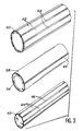
La figure 3 montre trois éléments permettant de réaliser un condensateur selon un premier mode de réalisation. Ces éléments sont constitués par :
- un
premier tube isolant 50 recouvert extérieurement d'une première couche conductrice formée de bandes 52 électriquement séparées les unes des autres par des intervalles 54, - un
deuxième tube isolant 56 recouvert d'une deuxième couche conductrice 58 coupéepar un intervalle 60, - un noyau central 62 recouvert d'une troisième couche conductrice formée de bandes 64 séparées par des intervalles 66.
- a first insulating
tube 50 externally covered with a first conductive layer formed bystrips 52 electrically separated from each other byintervals 54, - a second insulating
tube 56 covered with a secondconductive layer 58 cut by aninterval 60, - a
central core 62 covered with a third conductive layer formed bystrips 64 separated byintervals 66.
Le noyau 62 est emboîté dans le tube 56, lequel est emboîté dans le tube 50. On obtient ainsi un double condensateur avec trois armatures, l'armature centrale étant constituée par le conducteur 58 sur le tube 56.The
Dans ce mode de réalisation, les tubes isolants peuvent être en quartz, pyrex, macor (marques déposées), etc... Leur usinage est assuré au centième de millimètre. On peut aussi les réaliser en porcelaine par moulage.In this embodiment, the insulating tubes can be made of quartz, pyrex, macor (brands deposited), etc ... Their machining is assured to the hundredth of a millimeter. They can also be made of porcelain by molding.
Les couches conductrices peuvent être obtenues par dépôt de peinture d'argent directement étalée sur la surface extérieure des tubes et sur le noyau central, et par recuit vers 550°C. L'épaisseur de la couche conductrice est d'environ 2/100 mm.The conductive layers can be obtained by depositing silver paint directly spread on the outside surface of the tubes and on the central core, and by annealing at around 550 ° C. The thickness of the conductive layer is approximately 2/100 mm.
On peut encore obtenir de tels tubes en déposant un matériau conducteur sur un isolant plat (par exemple en mica), en gravant ce conducteur pour obtenir des bandes, puis en enroulant l'ensemble pour obtenir un tube au diamètre désiré. On peut aussi coller des bandes conductrices sur un tube isolant.One can also obtain such tubes by depositing a conductive material on a flat insulator (for example in mica), by etching this conductor to obtain strips, then by winding the assembly to obtain a tube with the desired diameter. You can also stick conductive strips on an insulating tube.
A titre purement explicatif, on peut avoir un premier tube 50 de diamètre extérieur 18 mm, de diamètre intérieur 16 mm et de longueur 105 mm, avec 6 à 8 bandes conductrices espacées d'un millimètre. Le second tube 56 peut avoir un diamètre extérieur de 15,9 mm, un diamètre intérieur de 13,9 mm et une longueur de 102 mm avec un espace d'un millimètre interrompant la couche conductrice. Enfin, le noyau 62 peut posséder un diamètre de 13,8 mm et une longueur de 102 mm. Il peut comprendre 6 ou 8 bandes espacées de 1 mm chacune. Par coulissage dans le tube 56, il permet de régler la valeur de la capacité totale.For purely explanatory purposes, there may be a
Ainsi constitué, le condensateur comprend deux ensembles de condensateurs, disposés en parallèle :
- un premier ensemble constitué par les bandes 52 du premier tube et la bande 58 du second ; dans l'exemple donné plus haut, chacun de ces condensateurs a une capacité fixe de 13 pF ;
- un second ensemble formé par les bandes 64 du
noyau 62 et la couche 58 du second tube ; dans l'exemple donné plus haut, les capacités varient entre 0 (noyau complétement retiré) et 3 pF (noyau complétement enfoncé).
- a first assembly constituted by the
bands 52 of the first tube and theband 58 of the second; in the example given above, each of these capacitors has a fixed capacity of 13 pF; - a second set formed by the
bands 64 of thecore 62 and thelayer 58 of the second tube; in the example given above, the capacities vary between 0 (nucleus completely removed) and 3 pF (nucleus fully inserted).
Les connexions entre ces diverses bandes et les secteurs du conducteur extérieur sont représentées sur la figure 4. Chacune des huit bandes 52 est reliée à l'une des huit bandes 64 et à l'un des huit secteurs 53 du conducteur extérieur. Le conducteur 58 du tube central n'est pas relié au conducteur extérieur mais à l'âme du câble coaxial d'alimentation (ce qui apparaîtra mieux sur la figure 7).The connections between these various bands and the sectors of the external conductor are shown in FIG. 4. Each of the eight
Un autre mode de réalisation du condensateur et représenté sur la figure 5. On retrouve le premier tube 50 de la figure 3 et ses bandes conductrices 52, à la différence près qu'il n'y a que N-1 bandes, au lieu de N, si N est le nombre de secteurs 53 du conducteur extérieur (il n'y aura donc, par exemple, que 7 bandes au lieu de 8). On retrouve également le noyau 62, à la différence près qu'il n'y a qu'une seule bande 72 (au lieu de 8) interrompue par un intervalle 74. Il n'existe plus alors qu'un seul condensateur variable, à savoir celui dont les armatures comprennent les couches 58 et 72. La capacité varie alors entre 0 et 16 pF.Another embodiment of the capacitor and shown in Figure 5. We find the
Le mode d'interconnexion est alors modifié comme indiqué sur la figure 6. Sept des secteurs 53 sont reliés aux sept bandes 52 du tube extérieur et le huitième est relié au conducteur unique 72 du noyau.The interconnection mode is then modified as indicated in FIG. 6. Seven of the
La figure 7 montre, en coupe, un résonateur coaxial équipé d'un condensateur réparti le long du conducteur central. On retrouve les éléments déjà représentés sur la figure 1, à savoir les flacons 22 (qui n'ont plus ici la forme hémisphérique mais une forme cylindrique), le conducteur extérieur 20, le conducteur central 10 et le câble coaxial d'alimentation 30. Selon l'invention, le conducteur central 10 est constitué par une des armatures emboîtées les unes dans les autres, soit 80, 82, 84 et de préférence par 82. Les armatures 80 et 84 sont connectées au conducteur extérieur 20 comme illustré sur les figures 4 et 6 déjà décrites et l'armature centrale 82 est reliée à l'âme du câble d'alimentation 30, l'adaptation s'effectuant toujours par une boucle.Figure 7 shows, in section, a coaxial resonator equipped with a capacitor distributed along the central conductor. We find the elements already represented in FIG. 1, namely the bottles 22 (which no longer have the hemispherical shape here but a cylindrical shape), the
Le réglage de la capacité totale peut s'effectuer en ajustant l'enfoncement du noyau, par exemple par rotation au moyen d'un tourne-vis 90 si un filetage a été prévu entre le noyau et l'armature 82 dans lequel il est emboîté.The adjustment of the total capacity can be carried out by adjusting the depression of the core, for example by rotation by means of a
Il faut observer, à ce stade de la description de l'invention, que l'on connaît déjà des condensateurs cylindriques réglables formés de deux armatures cylindriques emboîtées plus ou moins l'une dans l'autre. Le document de brevet français FR-A-2 092 998 décrit un tel condensateur, en particulier, pour les magnétomètres à RMN. La présente invention se distingue de cet art antérieur moins par la structure en soi du condensateur que par son agencement dans le résonateur complet. Ce point peut être souligné grâce à la figure 8, qui montre le schéma électrique équivalent d'un résonateur selon l'invention.It should be observed, at this stage of the description of the invention, that there are already known adjustable cylindrical capacitors formed by two cylindrical armatures more or less nested one inside the other. French patent document FR-A-2 092 998 describes such a capacitor, in particular for NMR magnetometers. The present invention differs from this prior art less by the structure per se of the capacitor than by its arrangement in the complete resonator. This point can be underlined thanks to FIG. 8, which shows the equivalent electrical diagram of a resonator according to the invention.
Sur cette figure, on voit (partie (a)) le résonateur 100 avec un conducteur central 10, un conducteur extérieur 20. Ce résonateur est relié à une inductance d'adaptation 42. A cet égard, le schéma est celui-là même de la figure 2 partie (a). Mais à la différence de l'art antérieur, on ne trouve plus de condensateur réglable en bout de résonateur tel que 44 sur la figure 2, mais un condensateur réparti tout le long du conducteur central (armatures 101 et 102). La partie (b) de la figure 8 montre le schéma électrique équivalent d'une tranche élémentaire de ce résonateur entre les cotes z et z+dz. On y retrouve, comme sur la partie (b) de la figure 2, les inductances réparties L/2, les résistances réparties R/2, le condensateur réparti C avec sa résistance en parallèle R′ ; mais le schéma de la figure 8 offre cette particularité de présenter un condensateur réglable réparti C′. Dans le dispositif du document FR-A-2 092 998 le condensateur cylindrique est placé en bout de résonateur, comme dans le schéma de la partie (a) de la figure 2 (référence 44). On retrouve donc, avec cette structure antérieure, tous les inconvénients énoncés plus haut, auxquels l'invention remédie grâce à la répartition du condensateur d'accord.In this figure, we see (part (a)) the
Les figures 9 à 13 montrent d'autres modes de réalisation du résonateur de l'invention.Figures 9 to 13 show other embodiments of the resonator of the invention.
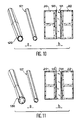
Sur la figure 9 tout d'abord, on voit (partie a) un tube isolant 110 recouvert extérieurement d'une couche conductrice 112 et intérieurement d'une couche conductrice 111, toutes deux en forme de bandes. L'accord est obtenu par introduction d'un noyau 113 recouvert intérieurement d'une couche conductrice 114.In FIG. 9 first of all, we see (part a) an insulating
Sur les figures 10 et 11, le tube extérieur ne présente pas la même épaisseur sur toute sa longueur, de sorte que la capacité répartie varie le long de l'axe du résonateur. Sur la figure 10, partie a, le tube 120 est plus épais en son milieu qu'à ses extrémités tandis que, sur la figure 11, partie a, le tube 130 est plus mince en son milieu qu'à ses extrémités. Dans les deux cas, il est prévu un tube intérieur respectivement 121 et 131 (constituant par exemple le conducteur central).In FIGS. 10 and 11, the outer tube does not have the same thickness over its entire length, so that the distributed capacity varies along the axis of the resonator. In FIG. 10, part a, the
La figure 12 montre deux variantes où la couche conductrice extérieure présente la forme de bandes hélicoïdales larges 140 (partie a) ou étroites 141 (partie b).Figure 12 shows two variants where the outer conductive layer has the form of wide helical bands 140 (part a) or narrow 141 (part b).
Enfin, la figure 13 montre un mode de réalisation où le condensateur de réglage est disposé à l'extérieur du résonateur. Ce condensateur comprend, par exemple, deux tubes 150 et 152 emboîtés l'un dans l'autre et recouverts de bandes conductrices (le conducteur central 10 étant constitué de façon classique).Finally, Figure 13 shows an embodiment where the adjustment capacitor is arranged outside the resonator. This capacitor comprises, for example, two
Claims (14)
Applications Claiming Priority (2)
| Application Number | Priority Date | Filing Date | Title |
|---|---|---|---|
| FR9002347 | 1990-02-26 | ||
| FR9002347A FR2658955B1 (en) | 1990-02-26 | 1990-02-26 | COAXIAL RESONATOR WITH DISTRIBUTED TUNING CAPACITY. |
Publications (2)
| Publication Number | Publication Date |
|---|---|
| EP0445017A1 true EP0445017A1 (en) | 1991-09-04 |
| EP0445017B1 EP0445017B1 (en) | 1995-09-06 |
Family
ID=9394125
Family Applications (1)
| Application Number | Title | Priority Date | Filing Date |
|---|---|---|---|
| EP91400505A Expired - Lifetime EP0445017B1 (en) | 1990-02-26 | 1991-02-25 | Coaxial resonator with distributed tuning capacity |
Country Status (6)
| Country | Link |
|---|---|
| US (1) | US5172085A (en) |
| EP (1) | EP0445017B1 (en) |
| CA (1) | CA2036692C (en) |
| DE (1) | DE69112672T2 (en) |
| FR (1) | FR2658955B1 (en) |
| NO (1) | NO910762L (en) |
Cited By (3)
| Publication number | Priority date | Publication date | Assignee | Title |
|---|---|---|---|---|
| EP0631150A1 (en) * | 1993-06-24 | 1994-12-28 | Commissariat A L'energie Atomique | NMR sonde with controlled oscillator loop |
| US6984980B2 (en) | 2002-02-14 | 2006-01-10 | Baker Hughes Incorporated | Method and apparatus for NMR sensor with loop-gap resonator |
| EP3104453A1 (en) * | 2015-06-10 | 2016-12-14 | Alcatel Lucent | A resonator assembly and filter |
Families Citing this family (16)
| Publication number | Priority date | Publication date | Assignee | Title |
|---|---|---|---|---|
| US5565778A (en) * | 1992-06-01 | 1996-10-15 | Conductus, Inc. | Nuclear magnetic resonance probe coil |
| US6083883A (en) * | 1996-04-26 | 2000-07-04 | Illinois Superconductor Corporation | Method of forming a dielectric and superconductor resonant structure |
| JP2003500133A (en) | 1999-05-21 | 2003-01-07 | ザ ゼネラル ホスピタル コーポレーション | RF coil for imaging system |
| US7598739B2 (en) * | 1999-05-21 | 2009-10-06 | Regents Of The University Of Minnesota | Radio frequency gradient, shim and parallel imaging coil |
| JP3478219B2 (en) * | 1999-12-28 | 2003-12-15 | 株式会社村田製作所 | Resonator, resonance element, resonator device, filter, duplexer, and communication device |
| EP2034325A1 (en) | 2000-07-31 | 2009-03-11 | Regents of the University of Minnesota | Open tem resonators for mri |
| US7405361B1 (en) * | 2002-02-26 | 2008-07-29 | Electrolock, Inc. | Nested insulating tube assembly for a coil lead |
| US6894584B2 (en) | 2002-08-12 | 2005-05-17 | Isco International, Inc. | Thin film resonators |
| CN1317792C (en) * | 2003-02-25 | 2007-05-23 | 富士通株式会社 | Superconductor transmission line |
| US20050264291A1 (en) * | 2004-05-07 | 2005-12-01 | Vaughan J T | Multi-current elements for magnetic resonance radio frequency coils |
| JP4633724B2 (en) * | 2004-06-25 | 2011-02-16 | パナソニック株式会社 | Electromechanical filter |
| NO20053093D0 (en) * | 2005-06-23 | 2005-06-23 | Radiumhospitalets Forskningsst | A device for MRI solenoid coils and method for adjusting same. |
| US7928877B1 (en) * | 2008-07-23 | 2011-04-19 | Hrl Laboratories, Llc | Continuous-time delta-sigma modulator with small distributed resonators |
| US9660336B2 (en) * | 2013-02-07 | 2017-05-23 | Kevan ANDERSON | Systems, devices and methods for transmitting electrical signals through a faraday cage |
| US10578689B2 (en) | 2015-12-03 | 2020-03-03 | Innovere Medical Inc. | Systems, devices and methods for wireless transmission of signals through a faraday cage |
| BR112019023421A2 (en) | 2017-05-09 | 2020-06-16 | Innovere Medical Inc. | MAGNETIC RESONANT IMAGE GENERATION AND COMMUNICATION SYSTEM, AND WIRELESS COMMUNICATION SYSTEM. |
Citations (4)
| Publication number | Priority date | Publication date | Assignee | Title |
|---|---|---|---|---|
| GB627340A (en) * | 1944-06-02 | 1949-08-08 | Philips Nv | Improvements in or relating to tunable electric resonators |
| FR2092998A5 (en) * | 1970-05-15 | 1972-01-28 | Anvar | |
| FR2098624A5 (en) * | 1970-07-22 | 1972-03-10 | Commissariat Energie Atomique | |
| US4717880A (en) * | 1985-08-23 | 1988-01-05 | Jeol Ltd. | ESR spectrometer having split-ring resonator |
Family Cites Families (3)
| Publication number | Priority date | Publication date | Assignee | Title |
|---|---|---|---|---|
| US4751464A (en) * | 1987-05-04 | 1988-06-14 | Advanced Nmr Systems, Inc. | Cavity resonator with improved magnetic field uniformity for high frequency operation and reduced dielectric heating in NMR imaging devices |
| US4820985A (en) * | 1988-04-06 | 1989-04-11 | General Electric Company | Apparatus for tuning an NMR field coil |
| DE3839046A1 (en) * | 1988-11-18 | 1990-05-23 | Bruker Medizintech | SAMPLE HEAD FOR NMR TOMOGRAPHY |
-
1990
- 1990-02-26 FR FR9002347A patent/FR2658955B1/en not_active Expired - Lifetime
-
1991
- 1991-02-14 US US07/655,828 patent/US5172085A/en not_active Expired - Lifetime
- 1991-02-20 CA CA002036692A patent/CA2036692C/en not_active Expired - Lifetime
- 1991-02-25 DE DE69112672T patent/DE69112672T2/en not_active Expired - Lifetime
- 1991-02-25 EP EP91400505A patent/EP0445017B1/en not_active Expired - Lifetime
- 1991-02-26 NO NO91910762A patent/NO910762L/en unknown
Patent Citations (4)
| Publication number | Priority date | Publication date | Assignee | Title |
|---|---|---|---|---|
| GB627340A (en) * | 1944-06-02 | 1949-08-08 | Philips Nv | Improvements in or relating to tunable electric resonators |
| FR2092998A5 (en) * | 1970-05-15 | 1972-01-28 | Anvar | |
| FR2098624A5 (en) * | 1970-07-22 | 1972-03-10 | Commissariat Energie Atomique | |
| US4717880A (en) * | 1985-08-23 | 1988-01-05 | Jeol Ltd. | ESR spectrometer having split-ring resonator |
Non-Patent Citations (2)
| Title |
|---|
| ELECTRONIC COMPONENTS AND APPLICATIONS. vol. 6, no. 2, 1984, EINDHOVEN NL pages 83 - 86; H.FIEDELDY: "VHF power amplifiers_with broadband input circuitry" * |
| JOURNAL OF PHYSICS E. SCIENTIFIC INSTRUMENTS. vol. 2, no. 12, décembre 1969, ISHING, BRISTOL GB pages 1036 - 1040; M.DECORPS ET AL.: "Etude comparative de divers types de volumes resonnants pour spectrometres a resonance paramagnetique electronique....." * |
Cited By (6)
| Publication number | Priority date | Publication date | Assignee | Title |
|---|---|---|---|---|
| EP0631150A1 (en) * | 1993-06-24 | 1994-12-28 | Commissariat A L'energie Atomique | NMR sonde with controlled oscillator loop |
| FR2707014A1 (en) * | 1993-06-24 | 1994-12-30 | Commissariat Energie Atomique | |
| US5528143A (en) * | 1993-06-24 | 1996-06-18 | Commissariat A L'energie Atomique | Loop oscillator NMR probe |
| US6984980B2 (en) | 2002-02-14 | 2006-01-10 | Baker Hughes Incorporated | Method and apparatus for NMR sensor with loop-gap resonator |
| EP3104453A1 (en) * | 2015-06-10 | 2016-12-14 | Alcatel Lucent | A resonator assembly and filter |
| WO2016198466A1 (en) * | 2015-06-10 | 2016-12-15 | Alcatel Lucent | A resonator assembly and filter |
Also Published As
| Publication number | Publication date |
|---|---|
| FR2658955B1 (en) | 1992-04-30 |
| DE69112672T2 (en) | 1996-05-02 |
| CA2036692C (en) | 2001-07-10 |
| EP0445017B1 (en) | 1995-09-06 |
| US5172085A (en) | 1992-12-15 |
| NO910762D0 (en) | 1991-02-26 |
| FR2658955A1 (en) | 1991-08-30 |
| DE69112672D1 (en) | 1995-10-12 |
| NO910762L (en) | 1991-08-27 |
| CA2036692A1 (en) | 1991-08-27 |
Similar Documents
| Publication | Publication Date | Title |
|---|---|---|
| EP0445017B1 (en) | Coaxial resonator with distributed tuning capacity | |
| US6980000B2 (en) | Coils for high frequency MRI | |
| EP0109867B1 (en) | Sensitive broad band alternating magnetic field detector, and its use as a measuring apparatus | |
| EP0117178B1 (en) | Microwave filter with line-shaped resonators | |
| EP1145379B1 (en) | Antenna provided with an assembly of filtering materials | |
| EP1607761B1 (en) | Multi-frequency power supply and probe and NMR spectrometer including such a power supply | |
| EP0209412B1 (en) | High-frequency antenna for an apparatus mesuring nuclear magnetic resonance | |
| EP2534499B1 (en) | Linear resonator of a high-frequency antenna for a nuclear magnetic resonance imaging apparatus | |
| EP0667984A1 (en) | Monopolar wire-plate antenna | |
| FR2557298A1 (en) | INTEGRATED RADIOFREQUENCY COIL FOR NUCLEAR MAGNETIC RESONANCE TECHNIQUES | |
| FR2597266A1 (en) | BROADBAND ANTENNA | |
| FR3090220A1 (en) | MONOPOLAR WIRE-PLATE ANTENNA | |
| EP1711839A1 (en) | High-frequency resonant cavity for nuclear magnetic resonance, using radio-frequency transmission lines | |
| EP0451054B1 (en) | Compact NMR probe | |
| EP0487388B1 (en) | Inductor, particularly for short waves | |
| EP0206931A1 (en) | NMR magnetometer probe with a centrally tuned cavity having a divided central cross-sectional slice | |
| EP0072729B1 (en) | Coaxial bandstop filter | |
| FR2833412A1 (en) | Earth's magnetic field precise measurement having resonator central conductor external conductor connected and connecting coaxial cable having parallel extension central conductor parallel forming extended loop. | |
| EP0013204A1 (en) | Frequency-band filter | |
| EP0594502A1 (en) | Tunable microwave bandpass filter with dual mode cavities | |
| CA2448636C (en) | Antenna provided with an assembly of filtering materials | |
| BE521287A (en) | ||
| CH441448A (en) | High frequency oscillator | |
| BE480487A (en) | ||
| BE473054A (en) |
Legal Events
| Date | Code | Title | Description |
|---|---|---|---|
| PUAI | Public reference made under article 153(3) epc to a published international application that has entered the european phase |
Free format text: ORIGINAL CODE: 0009012 |
|
| AK | Designated contracting states |
Kind code of ref document: A1 Designated state(s): BE DE GB IT NL SE |
|
| 17P | Request for examination filed |
Effective date: 19920207 |
|
| 17Q | First examination report despatched |
Effective date: 19940309 |
|
| GRAA | (expected) grant |
Free format text: ORIGINAL CODE: 0009210 |
|
| AK | Designated contracting states |
Kind code of ref document: B1 Designated state(s): BE DE GB IT NL SE |
|
| PG25 | Lapsed in a contracting state [announced via postgrant information from national office to epo] |
Ref country code: NL Free format text: LAPSE BECAUSE OF FAILURE TO SUBMIT A TRANSLATION OF THE DESCRIPTION OR TO PAY THE FEE WITHIN THE PRESCRIBED TIME-LIMIT Effective date: 19950906 |
|
| REF | Corresponds to: |
Ref document number: 69112672 Country of ref document: DE Date of ref document: 19951012 |
|
| ITF | It: translation for a ep patent filed |
Owner name: JACOBACCI & PERANI S.P.A. |
|
| PG25 | Lapsed in a contracting state [announced via postgrant information from national office to epo] |
Ref country code: SE Effective date: 19951206 |
|
| NLV1 | Nl: lapsed or annulled due to failure to fulfill the requirements of art. 29p and 29m of the patents act | ||
| PG25 | Lapsed in a contracting state [announced via postgrant information from national office to epo] |
Ref country code: BE Effective date: 19960228 |
|
| GBT | Gb: translation of ep patent filed (gb section 77(6)(a)/1977) |
Effective date: 19951116 |
|
| PLBE | No opposition filed within time limit |
Free format text: ORIGINAL CODE: 0009261 |
|
| STAA | Information on the status of an ep patent application or granted ep patent |
Free format text: STATUS: NO OPPOSITION FILED WITHIN TIME LIMIT |
|
| 26N | No opposition filed | ||
| BERE | Be: lapsed |
Owner name: COMMISSARIAT A L'ENERGIE ATOMIQUE Effective date: 19960228 |
|
| REG | Reference to a national code |
Ref country code: GB Ref legal event code: IF02 |
|
| PGFP | Annual fee paid to national office [announced via postgrant information from national office to epo] |
Ref country code: IT Payment date: 20100226 Year of fee payment: 20 |
|
| PGFP | Annual fee paid to national office [announced via postgrant information from national office to epo] |
Ref country code: GB Payment date: 20100226 Year of fee payment: 20 Ref country code: DE Payment date: 20100312 Year of fee payment: 20 |
|
| REG | Reference to a national code |
Ref country code: DE Ref legal event code: R071 Ref document number: 69112672 Country of ref document: DE |
|
| REG | Reference to a national code |
Ref country code: GB Ref legal event code: PE20 Expiry date: 20110224 |
|
| PG25 | Lapsed in a contracting state [announced via postgrant information from national office to epo] |
Ref country code: GB Free format text: LAPSE BECAUSE OF EXPIRATION OF PROTECTION Effective date: 20110224 |
|
| PG25 | Lapsed in a contracting state [announced via postgrant information from national office to epo] |
Ref country code: DE Free format text: LAPSE BECAUSE OF EXPIRATION OF PROTECTION Effective date: 20110225 |