EP0445733A1 - Spindle motor - Google Patents
Spindle motor Download PDFInfo
- Publication number
- EP0445733A1 EP0445733A1 EP91103312A EP91103312A EP0445733A1 EP 0445733 A1 EP0445733 A1 EP 0445733A1 EP 91103312 A EP91103312 A EP 91103312A EP 91103312 A EP91103312 A EP 91103312A EP 0445733 A1 EP0445733 A1 EP 0445733A1
- Authority
- EP
- European Patent Office
- Prior art keywords
- electromagnet
- motor
- thrust
- thrust bearing
- bearing
- Prior art date
- Legal status (The legal status is an assumption and is not a legal conclusion. Google has not performed a legal analysis and makes no representation as to the accuracy of the status listed.)
- Ceased
Links
Images


Classifications
-
- F—MECHANICAL ENGINEERING; LIGHTING; HEATING; WEAPONS; BLASTING
- F16—ENGINEERING ELEMENTS AND UNITS; GENERAL MEASURES FOR PRODUCING AND MAINTAINING EFFECTIVE FUNCTIONING OF MACHINES OR INSTALLATIONS; THERMAL INSULATION IN GENERAL
- F16C—SHAFTS; FLEXIBLE SHAFTS; ELEMENTS OR CRANKSHAFT MECHANISMS; ROTARY BODIES OTHER THAN GEARING ELEMENTS; BEARINGS
- F16C32/00—Bearings not otherwise provided for
- F16C32/04—Bearings not otherwise provided for using magnetic or electric supporting means
- F16C32/0406—Magnetic bearings
- F16C32/044—Active magnetic bearings
-
- F—MECHANICAL ENGINEERING; LIGHTING; HEATING; WEAPONS; BLASTING
- F16—ENGINEERING ELEMENTS AND UNITS; GENERAL MEASURES FOR PRODUCING AND MAINTAINING EFFECTIVE FUNCTIONING OF MACHINES OR INSTALLATIONS; THERMAL INSULATION IN GENERAL
- F16C—SHAFTS; FLEXIBLE SHAFTS; ELEMENTS OR CRANKSHAFT MECHANISMS; ROTARY BODIES OTHER THAN GEARING ELEMENTS; BEARINGS
- F16C17/00—Sliding-contact bearings for exclusively rotary movement
- F16C17/02—Sliding-contact bearings for exclusively rotary movement for radial load only
-
- F—MECHANICAL ENGINEERING; LIGHTING; HEATING; WEAPONS; BLASTING
- F16—ENGINEERING ELEMENTS AND UNITS; GENERAL MEASURES FOR PRODUCING AND MAINTAINING EFFECTIVE FUNCTIONING OF MACHINES OR INSTALLATIONS; THERMAL INSULATION IN GENERAL
- F16C—SHAFTS; FLEXIBLE SHAFTS; ELEMENTS OR CRANKSHAFT MECHANISMS; ROTARY BODIES OTHER THAN GEARING ELEMENTS; BEARINGS
- F16C17/00—Sliding-contact bearings for exclusively rotary movement
- F16C17/10—Sliding-contact bearings for exclusively rotary movement for both radial and axial load
- F16C17/102—Sliding-contact bearings for exclusively rotary movement for both radial and axial load with grooves in the bearing surface to generate hydrodynamic pressure
- F16C17/107—Sliding-contact bearings for exclusively rotary movement for both radial and axial load with grooves in the bearing surface to generate hydrodynamic pressure with at least one surface for radial load and at least one surface for axial load
-
- F—MECHANICAL ENGINEERING; LIGHTING; HEATING; WEAPONS; BLASTING
- F16—ENGINEERING ELEMENTS AND UNITS; GENERAL MEASURES FOR PRODUCING AND MAINTAINING EFFECTIVE FUNCTIONING OF MACHINES OR INSTALLATIONS; THERMAL INSULATION IN GENERAL
- F16C—SHAFTS; FLEXIBLE SHAFTS; ELEMENTS OR CRANKSHAFT MECHANISMS; ROTARY BODIES OTHER THAN GEARING ELEMENTS; BEARINGS
- F16C25/00—Bearings for exclusively rotary movement adjustable for wear or play
- F16C25/02—Sliding-contact bearings
- F16C25/04—Sliding-contact bearings self-adjusting
- F16C25/045—Sliding-contact bearings self-adjusting with magnetic means to preload the bearing
-
- F—MECHANICAL ENGINEERING; LIGHTING; HEATING; WEAPONS; BLASTING
- F16—ENGINEERING ELEMENTS AND UNITS; GENERAL MEASURES FOR PRODUCING AND MAINTAINING EFFECTIVE FUNCTIONING OF MACHINES OR INSTALLATIONS; THERMAL INSULATION IN GENERAL
- F16C—SHAFTS; FLEXIBLE SHAFTS; ELEMENTS OR CRANKSHAFT MECHANISMS; ROTARY BODIES OTHER THAN GEARING ELEMENTS; BEARINGS
- F16C32/00—Bearings not otherwise provided for
- F16C32/04—Bearings not otherwise provided for using magnetic or electric supporting means
- F16C32/0402—Bearings not otherwise provided for using magnetic or electric supporting means combined with other supporting means, e.g. hybrid bearings with both magnetic and fluid supporting means
-
- F—MECHANICAL ENGINEERING; LIGHTING; HEATING; WEAPONS; BLASTING
- F16—ENGINEERING ELEMENTS AND UNITS; GENERAL MEASURES FOR PRODUCING AND MAINTAINING EFFECTIVE FUNCTIONING OF MACHINES OR INSTALLATIONS; THERMAL INSULATION IN GENERAL
- F16C—SHAFTS; FLEXIBLE SHAFTS; ELEMENTS OR CRANKSHAFT MECHANISMS; ROTARY BODIES OTHER THAN GEARING ELEMENTS; BEARINGS
- F16C33/00—Parts of bearings; Special methods for making bearings or parts thereof
- F16C33/02—Parts of sliding-contact bearings
- F16C33/04—Brasses; Bushes; Linings
- F16C33/06—Sliding surface mainly made of metal
- F16C33/10—Construction relative to lubrication
- F16C33/1025—Construction relative to lubrication with liquid, e.g. oil, as lubricant
- F16C33/106—Details of distribution or circulation inside the bearings, e.g. details of the bearing surfaces to affect flow or pressure of the liquid
- F16C33/107—Grooves for generating pressure
-
- H—ELECTRICITY
- H02—GENERATION; CONVERSION OR DISTRIBUTION OF ELECTRIC POWER
- H02K—DYNAMO-ELECTRIC MACHINES
- H02K5/00—Casings; Enclosures; Supports
- H02K5/04—Casings or enclosures characterised by the shape, form or construction thereof
- H02K5/16—Means for supporting bearings, e.g. insulating supports or means for fitting bearings in the bearing-shields
- H02K5/165—Means for supporting bearings, e.g. insulating supports or means for fitting bearings in the bearing-shields radially supporting the rotor around a fixed spindle; radially supporting the rotor directly
-
- H—ELECTRICITY
- H02—GENERATION; CONVERSION OR DISTRIBUTION OF ELECTRIC POWER
- H02K—DYNAMO-ELECTRIC MACHINES
- H02K7/00—Arrangements for handling mechanical energy structurally associated with dynamo-electric machines, e.g. structural association with mechanical driving motors or auxiliary dynamo-electric machines
- H02K7/08—Structural association with bearings
- H02K7/09—Structural association with bearings with magnetic bearings
Definitions
- the present invention relates to a spindle motor which may be employed to drive, for example, a movable part of office automation equipment. More particularly, the present invention relates to a spindle motor which has high rigidity and a long lifetime.
- Ball bearings involve fundamental problems such that they require lubrication by means of grease and that it is difficult to improve the rotational accuracy and extend the lifetime thereof because the amount of axial vibration produced during rotation is relatively large.
- hydrodynamic bearings in place of ball bearings has been proposed.
- Fig. 5 is a sectional view of a spindle motor employing hydrodynamic bearings, which was filed by the same applicant prior to this application (Japanese Patent Application No. 01-179647). As illustrated, this spindle motor comprises a motor stator 1 and a motor rotor 6.
- the motor stator 1 comprises a base 2, a support shaft 3 that is stood on the central portion thereof, a thrust bearing pad 4 that is secured to the base 2, an annular radial bearing member 8 that is concentrically secured to the support shaft 3, and a stator 1 of a driving motor 5 that is secured to the support shaft 3 below the radial bearing member 8.
- the motor rotor 6 comprises a radial shaft sleeve 7 and a rotor 10 of the driving motor 5, which are secured inside a cylindrical member such that the radial shaft sleeve 7 faces the radial bearing member 8 and the rotor 10 faces the stator 11, together with a thrust bearing collar 9 that is secured to the lower end of the cylindrical member in opposing relation to the thrust bearing pad 4.
- the radial shaft sleeve 7 and the radial bearing member 8 face each other to form a herringbone groove hydrodynamic radial bearing, as shown in Fig. 6.
- the surface of the radial bearing member 8 that faces the radial shaft sleeve 7 is formed with grooves for generating dynamic pressure, for example, herringbone-shaped grooves C1.
- the thrust bearing pad 4 and the thrust bearing collar 9 face each other to form a spiral groove hydrodynamic thrust bearing 12.
- the surface of the thrust bearing pad 4 that faces the thrust bearing collar 9 is formed with grooves for generating dynamic pressure, for example, spiral grooves C2 shown in Fig. 7.
- the conventional spindle motor having the above-described arrangement suffers, however, from problems stated below.
- Hydrodynamic bearings particularly hydrodynamic thrust bearings, need large starting torque because of the large contact resistance at the time of starting and are, in many cases, required to have excessive motor performance.
- the thickness of the fluid layer in a hydrodynamic bearing increases, resulting in a lowering in the rotational rigidity.
- the axis of the rotor is inclined with respect to the support shaft, which leads to an increase in the starting torque because of local contact of the dynamic pressure surfaces.
- whirling of the shaft makes it impossible to obtain a satisfactory operating condition.
- the present invention provides a spindle motor having a motor stator, a motor rotor, and a driving motor having a stator secured to the motor stator and a rotor secured to the motor rotor, the motor rotor being rotatably supported by the motor stator through a thrust bearing and a radial bearing, of which at least the thrust bearing is a hydrodynamic bearing, wherein the improvement comprises a thrust load adjusting device which has an electromagnet that is provided on the motor stator and a permanent magnet that is provided on the motor rotor in opposing relation to the electromagnet to adjust the thrust load applied to the thrust bearing by controlling the current that is supplied to the electromagnet and thereby controlling the repelling force and/or attraction force that acts between the electromagnet and the permanent magnet.
- the current supplied to the electromagnet of the thrust load adjusting device may be controlled in accordance with the current that is supplied to the driving motor.
- the value of current supplied to the electromagnet of the thrust load adjusting device may be controlled in accordance with the value of current supplied to the driving motor when started.
- the present invention may be arranged such that, when the rotational speed of the driving motor reaches a predetermined value, the polarity of the electromagnet of the thrust load adjusting device is reversed to increase the force that is applied to the thrust bearing.
- an attraction force and/or repelling force acts between the permanent magnet and the electromagnet, and when the driving motor is started, the polarity of the electromagnet is set in a direction in which the thrust load is reduced, thereby reducing the thrust load at the time of starting the motor.
- the thrust load can be controlled by varying the current, it is possible to provide a fluid layer thickness which is sufficient to prevent solid contact between the constituent elements of the hydrodynamic thrust bearing and maintain the required rotational stability.
- Fig. 1 is a sectional view showing the structure of one embodiment of the spindle motor according to the present invention.
- the spindle motor of this embodiment is a so-called outer rotor type motor, which comprises a motor stator 1 and a motor rotor 6 and in which a support shaft 3 of the stator 1 is stationary and the cylindrical rotor 6, which is outside the support shaft 3, rotates.
- the same reference numerals as those in Fig. 5 denote the same or equivalent elements.
- An annular thrust bearing 12 is a spiral groove bearing that is arranged as shown in Fig. 7.
- a radial bearing member 8 is a herringbone groove bearing member. The inner surface of the motor rotor 6 and the annular radial bearing member 8 constitute in combination a radial bearing such as that shown in Fig. 6.
- herringbone-shaped grooves for generating dynamic pressure are usually formed in the surface of the radial bearing member 8 and spiral grooves for generating dynamic pressure are usually formed in the thrust bearing pad 4, it should be noted that herringbone-shaped grooves may be formed in the inner surface of the motor rotor 6 that faces the annular radial bearing member 8, with the outer peripheral surface of the radial bearing member 8 being smoothed and that spiral grooves may be formed in the surface of the thrust bearing collar 9 that faces the thrust bearing pad 4, with the surface of the bearing pad 4 being smoothed.
- the load adjusting device 41 for adjusting the load in the thrust direction.
- the load adjusting device 41 comprises an electromagnet 42 that is secured to the support shaft 3 and a permanent magnet 43 that is secured to the inner surface of the motor rotor 6 in opposing relation to the electromagnet 42.
- Figs. 2(a) and 2(b) are enlarged views of two examples of the load adjusting device 41.
- the electromagnet 42 is disposed in such a manner that the center thereof is closer to the thrust bearing 12 than the center of the permanent magnet 43 by the distance d.
- the figure shows a state where the coil 42a is energized so that the polarity of the electromagnet 42 is the same as that of the permanent magnet 43.
- the electromagnet 42 and the permanent magnet 43 face each other in the axial direction.
- the figure shows a state where the coil 42a is energized so that the polarity of the electromagnet 42 becomes opposite to that of the permanent magnet 43.
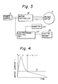
- Fig. 3 is a block diagram showing the arrangement of a controller for the spindle motor of the present invention
- Fig. 4 is a chart showing the control timing.
- the driving motor 5 of the spindle motor is supplied with driving current through a motor controller 52.
- the driving current is detected by an ammeter 53, and the output of the ammeter 53 is supplied to an electromagnet control unit 54.
- the control unit 54 controls the current supplied to the electromagnet 42 on the basis of the current value that is detected by the ammeter 53.
- Reference numeral 51 denotes a power source.
- the current I that is supplied to the driving motor 5 of the spindle motor is large at the time of starting and decreases after the starting, as shown in Fig. 4.
- the current I is detected by the ammeter 53 and the output of the ammeter 53 is input to the electromagnet control unit 54, as stated above.
- the electromagnet control unit 54 supplies the current to the electromagnet 42, whereas, when the motor current is not greater than the current value E, the control unit 54 suspends the energization of the electromagnet 42.
- the load adjusting device 41 is controlled by the electromagnet control unit 54 as follows.
- the electromagnet 42 is energized so that the electromagnet 42 has the same polarity as that of the permanent magnet 43. Accordingly, the attraction force that acts between the electromagnet 42 and the permanent magnet 43 increases, so that force Fo is generated to reduce the thrust load acting on the thrust bearing 12, thus reducing the starting torque at the time when the driving motor 5 is started and rotated at low speed.
- the electromagnet 42 is energized so that the polarity of the electromagnet 42 is opposite to that of the permanent magnet 43. Accordingly, the electromagnet 42 and the permanent magnet 43 repel each other to apply force Fo that reduces the thrust load acting on the thrust bearing 12, thus reducing the starting torque at the time when the driving motor 5 is started and rotated at low speed.
- the motor current I decreases to a level below the current value E
- the energization of the electromagnet 42 is suspended.
- the repelling force between the electromagnet 42 and the permanent magnet 43 is lost, and the thrust load acting on the thrust bearing 12 increases.
- the above-described electromagnet control unit 54 is arranged to control the supply of current to the electromagnet 42 according to whether or not the motor current exceeds a predetermined value
- the current supplied to the electromagnet 42 may be turned on/off in accordance with a change in the gradient of the motor current curve. It is also possible to turn on/off the current supplied to the electromagnet 42 according to whether or not the number of revolutions of the driving motor 5 exceeds a predetermined value by detecting it with a rotational speed sensor or the like.
- the spiral groove hydrodynamic bearing is enabled to exhibit considerably high rotational rigidity by increasing the load-carrying capacity and the preload. More specifically, the rotational rigidity can be enhanced by suspending the energization of the electromagnet 42 or reversing the polarity of the electromagnet 42 after the starting of the driving motor 5 to thereby increase the load on the hydrodynamic bearing.
Abstract
A spindle motor wherein a rotor (6) is supported by a stator (1) through a thrust bearing (13) and a radial bearing (8). At least the thrust bearing (13) is a hydrodynamic bearing. The spindle motor is provided with a device for adjusting the thrust load that is applied to the thrust bearing (13). The load adjusting device has an electromagnet (42) that is provided on the stator (1) and a permanent magnet (43) that is provided on the rotor (6) in opposing relation to the electromagnet (42). Either the repelling force or the attraction force, which acts between the electromagnet (42) and the permanent magnet (43) is controlled by changing the current supplied to the electromagnet.
Description
- The present invention relates to a spindle motor which may be employed to drive, for example, a movable part of office automation equipment. More particularly, the present invention relates to a spindle motor which has high rigidity and a long lifetime.
- With the achievement of hard disk drivers having a high storage capacity and low power consumption, demand has been made for improvements in the performance of spindle motors which are used to drive them so as they may be made even more suitable therefor. For example, spindle motors having high rigidity and a long life have been demanded.
- Conventional spindle motors of the type described above generally employ ball bearings. Ball bearings involve fundamental problems such that they require lubrication by means of grease and that it is difficult to improve the rotational accuracy and extend the lifetime thereof because the amount of axial vibration produced during rotation is relatively large. In order to solve these problems, employment of hydrodynamic bearings in place of ball bearings has been proposed.
- Fig. 5 is a sectional view of a spindle motor employing hydrodynamic bearings, which was filed by the same applicant prior to this application (Japanese Patent Application No. 01-179647). As illustrated, this spindle motor comprises a
motor stator 1 and amotor rotor 6. - The
motor stator 1 comprises abase 2, asupport shaft 3 that is stood on the central portion thereof, athrust bearing pad 4 that is secured to thebase 2, an annular radial bearingmember 8 that is concentrically secured to thesupport shaft 3, and astator 1 of adriving motor 5 that is secured to thesupport shaft 3 below the radial bearingmember 8. Themotor rotor 6 comprises aradial shaft sleeve 7 and arotor 10 of the drivingmotor 5, which are secured inside a cylindrical member such that theradial shaft sleeve 7 faces the radial bearingmember 8 and therotor 10 faces thestator 11, together with a thrust bearingcollar 9 that is secured to the lower end of the cylindrical member in opposing relation to the thrust bearingpad 4. Theradial shaft sleeve 7 and the radial bearingmember 8 face each other to form a herringbone groove hydrodynamic radial bearing, as shown in Fig. 6. The surface of the radial bearingmember 8 that faces theradial shaft sleeve 7 is formed with grooves for generating dynamic pressure, for example, herringbone-shaped grooves C₁. - The thrust bearing
pad 4 and the thrust bearingcollar 9 face each other to form a spiral groove hydrodynamic thrust bearing 12. The surface of the thrust bearingpad 4 that faces the thrust bearingcollar 9 is formed with grooves for generating dynamic pressure, for example, spiral grooves C₂ shown in Fig. 7. - The conventional spindle motor having the above-described arrangement suffers, however, from problems stated below. Hydrodynamic bearings, particularly hydrodynamic thrust bearings, need large starting torque because of the large contact resistance at the time of starting and are, in many cases, required to have excessive motor performance. When the number of revolutions increases, the thickness of the fluid layer in a hydrodynamic bearing increases, resulting in a lowering in the rotational rigidity. As a result, the axis of the rotor is inclined with respect to the support shaft, which leads to an increase in the starting torque because of local contact of the dynamic pressure surfaces. In addition, whirling of the shaft makes it impossible to obtain a satisfactory operating condition.
- In view of the above-described circumstances, it is an object of the present invention to provide a spindle motor of high rigidity and long life, which is designed so that the starting torque of the hydrodynamic thrust bearing is minimized and the rotational stability during high-speed rotation is enhanced.
- To this end, the present invention provides a spindle motor having a motor stator, a motor rotor, and a driving motor having a stator secured to the motor stator and a rotor secured to the motor rotor, the motor rotor being rotatably supported by the motor stator through a thrust bearing and a radial bearing, of which at least the thrust bearing is a hydrodynamic bearing, wherein the improvement comprises a thrust load adjusting device which has an electromagnet that is provided on the motor stator and a permanent magnet that is provided on the motor rotor in opposing relation to the electromagnet to adjust the thrust load applied to the thrust bearing by controlling the current that is supplied to the electromagnet and thereby controlling the repelling force and/or attraction force that acts between the electromagnet and the permanent magnet.
- The current supplied to the electromagnet of the thrust load adjusting device may be controlled in accordance with the current that is supplied to the driving motor.
- The value of current supplied to the electromagnet of the thrust load adjusting device may be controlled in accordance with the value of current supplied to the driving motor when started.
- The present invention may be arranged such that, when the rotational speed of the driving motor reaches a predetermined value, the polarity of the electromagnet of the thrust load adjusting device is reversed to increase the force that is applied to the thrust bearing.
- By virtue of the above-described arrangement, an attraction force and/or repelling force acts between the permanent magnet and the electromagnet, and when the driving motor is started, the polarity of the electromagnet is set in a direction in which the thrust load is reduced, thereby reducing the thrust load at the time of starting the motor.
- Since the thrust load can be controlled by varying the current, it is possible to provide a fluid layer thickness which is sufficient to prevent solid contact between the constituent elements of the hydrodynamic thrust bearing and maintain the required rotational stability.
- When the rotational speed of the motor rotor increases, the hydrodynamic pressure increases and the thickness of the fluid layer increases excessively, resulting in a lowering in the rotational stability. However, if the polarity of the electromagnet is made reverse to that employed at the time of starting the motor, the thrust load increases and the thickness of the fluid layer becomes sufficient to maintain the required rotational stability.
- Fig. 1 is a sectional view showing the structure of one embodiment of the spindle motor according to the present invention;
- Figs. 2(a) and 2(b) show the structures of two examples of a load adjusting device;
- Fig. 3 is a block diagram showing the arrangement of a controller for the spindle motor according to the present invention;
- Fig. 4 is a chart showing the control timing;
- Fig. 5 is a sectional view showing the structure of a conventional spindle motor;
- Fig. 6 exemplarily shows dynamic pressure generating grooves formed in a radial bearing member; and
- Fig. 7 exemplarily shows dynamic pressure generating grooves formed in a thrust bearing member.
- One embodiment of the present invention will be described below in detail with reference to the accompanying drawings.
- Fig. 1 is a sectional view showing the structure of one embodiment of the spindle motor according to the present invention. The spindle motor of this embodiment is a so-called outer rotor type motor, which comprises a
motor stator 1 and amotor rotor 6 and in which asupport shaft 3 of thestator 1 is stationary and thecylindrical rotor 6, which is outside thesupport shaft 3, rotates. In Fig. 1, the same reference numerals as those in Fig. 5 denote the same or equivalent elements. - An annular thrust bearing 12 is a spiral groove bearing that is arranged as shown in Fig. 7. A radial bearing
member 8 is a herringbone groove bearing member. The inner surface of themotor rotor 6 and the annular radial bearingmember 8 constitute in combination a radial bearing such as that shown in Fig. 6. - Although herringbone-shaped grooves for generating dynamic pressure are usually formed in the surface of the radial bearing
member 8 and spiral grooves for generating dynamic pressure are usually formed in the thrust bearingpad 4, it should be noted that herringbone-shaped grooves may be formed in the inner surface of themotor rotor 6 that faces the annular radial bearingmember 8, with the outer peripheral surface of the radial bearingmember 8 being smoothed and that spiral grooves may be formed in the surface of the thrust bearingcollar 9 that faces the thrust bearingpad 4, with the surface of thebearing pad 4 being smoothed. - Above the driving
motor 5 is provided a thrust load adjustingdevice 41 for adjusting the load in the thrust direction. Theload adjusting device 41 comprises anelectromagnet 42 that is secured to thesupport shaft 3 and apermanent magnet 43 that is secured to the inner surface of themotor rotor 6 in opposing relation to theelectromagnet 42. Figs. 2(a) and 2(b) are enlarged views of two examples of the load adjustingdevice 41. - In the
load adjusting device 41 shown in Fig. 2(a), theelectromagnet 42 is disposed in such a manner that the center thereof is closer to the thrust bearing 12 than the center of thepermanent magnet 43 by the distance d. The figure shows a state where thecoil 42a is energized so that the polarity of theelectromagnet 42 is the same as that of thepermanent magnet 43. - In the
load adjusting device 41 shown in Fig. 2(b), theelectromagnet 42 and thepermanent magnet 43 face each other in the axial direction. The figure shows a state where thecoil 42a is energized so that the polarity of theelectromagnet 42 becomes opposite to that of thepermanent magnet 43. - In either of the load adjusting
devices 41 shown in Figs. 2(a) and 2(b), when thecoil 42a of theelectromagnet 42 is not energized, thecore 42b of theelectromagnet 42 is attracted by the attraction force from thepermanent magnet 43, so that themotor rotor 6 is pushed down relative to themotor stator 1, causing contact pressure Fc to act on the thrust bearing 12. In other words, the thrust bearingcollar 9 is pressed against the thrust bearingpad 4 with the contact pressure Fc. When thecoil 42a of theelectromagnet 42 is energized, theelectromagnet 42 and thepermamanent magnet 43 repel each other, causing force Fo to act in a direction in which the contact load on the thrust bearing 12 is reduced. Accordingly, the load that is applied to the thrust bearing 12 can be adjusted to a proper value by controlling the value of current supplied to thecoil 42a of theelectromagnet 42. - If the energization of the
coil 42a is suspended or the direction of the current supplied thereto is changed to reverse the polarity of theelectromagnet 42, attraction force acts between theelectromagnet 42 and thepermanent magnet 43, so that the load applied to the thrust bearing 12 can be increased. Accordingly, in a case where, as the number of revolutions of the spindle motor increases, the thickness of the fluid layer that generates dynamic pressure in the thrust bearing 12 increases excessively and makes the rotation unstable, it is possible to prevent the rotation from becoming unstable by controlling the current that is supplied to thecoil 42a of the electromagnet 42 (or reversing the polarity). - A method of controlling the load adjusting
device 41 having the above-described arrangement will be explained below with reference to Figs. 3 and 4. Fig. 3 is a block diagram showing the arrangement of a controller for the spindle motor of the present invention, and Fig. 4 is a chart showing the control timing. - Referring to Fig. 3, the
driving motor 5 of the spindle motor is supplied with driving current through amotor controller 52. The driving current is detected by anammeter 53, and the output of theammeter 53 is supplied to anelectromagnet control unit 54. Thecontrol unit 54 controls the current supplied to theelectromagnet 42 on the basis of the current value that is detected by theammeter 53.Reference numeral 51 denotes a power source. - The current I that is supplied to the
driving motor 5 of the spindle motor is large at the time of starting and decreases after the starting, as shown in Fig. 4. The current I is detected by theammeter 53 and the output of theammeter 53 is input to theelectromagnet control unit 54, as stated above. When the motor current I is above a predetermined current value E, theelectromagnet control unit 54 supplies the current to theelectromagnet 42, whereas, when the motor current is not greater than the current value E, thecontrol unit 54 suspends the energization of theelectromagnet 42. Accordingly, during period C that the drivingmotor 5 is started and the current value I exceeds the current value E, the current is supplied to theelectromagnet 42, whereas, when the current value I becomes not greater than the current value E, the energization of theelectromagnet 42 is suspended. - Thus, the
load adjusting device 41 is controlled by theelectromagnet control unit 54 as follows. In the case of theload adjusting device 41 having the structure shown in Fig. 2(a), during the period C theelectromagnet 42 is energized so that theelectromagnet 42 has the same polarity as that of thepermanent magnet 43. Accordingly, the attraction force that acts between theelectromagnet 42 and thepermanent magnet 43 increases, so that force Fo is generated to reduce the thrust load acting on thethrust bearing 12, thus reducing the starting torque at the time when the drivingmotor 5 is started and rotated at low speed. When the number of revolutions of the drivingmotor 5 increases and the motor current I decreases to a level below the current value E, the energization of theelectromagnet 42 is suspended, and a large thrust load is applied by the attraction force from thepermanent magnet 43 and the overall weight of themotor rotor 6 and other members. - In the case of the
load adjusting device 41 having the structure shown in Fig. 2(b), during the period C theelectromagnet 42 is energized so that the polarity of theelectromagnet 42 is opposite to that of thepermanent magnet 43. Accordingly, theelectromagnet 42 and thepermanent magnet 43 repel each other to apply force Fo that reduces the thrust load acting on thethrust bearing 12, thus reducing the starting torque at the time when the drivingmotor 5 is started and rotated at low speed. When the number of revolutions of the drivingmotor 5 increases and the motor current I decreases to a level below the current value E, the energization of theelectromagnet 42 is suspended. Thus, the repelling force between theelectromagnet 42 and thepermanent magnet 43 is lost, and the thrust load acting on the thrust bearing 12 increases. - Although the above-described
electromagnet control unit 54 is arranged to control the supply of current to theelectromagnet 42 according to whether or not the motor current exceeds a predetermined value, it should be noted that the current supplied to theelectromagnet 42 may be turned on/off in accordance with a change in the gradient of the motor current curve. It is also possible to turn on/off the current supplied to theelectromagnet 42 according to whether or not the number of revolutions of the drivingmotor 5 exceeds a predetermined value by detecting it with a rotational speed sensor or the like. - In addition, the spiral groove hydrodynamic bearing is enabled to exhibit considerably high rotational rigidity by increasing the load-carrying capacity and the preload. More specifically, the rotational rigidity can be enhanced by suspending the energization of the
electromagnet 42 or reversing the polarity of theelectromagnet 42 after the starting of the drivingmotor 5 to thereby increase the load on the hydrodynamic bearing. - The spindle motor of the present invention provides the following advantageous effects:
- (1) The thrust load adjusting device enables a reduction in the starting torque of the spiral groove hydrodynamic bearing. Accordingly, it is unnecessary to increase the capacity of the driving motor of the spindle motor in consideration of the starting torque.
- (2) Since the driving torque is reduced by the thrust load adjusting device, a thrust bearing with a large load-carrying capacity can be used without taking care of the starting torque. In addition, since the thrust load adjusting device enables a large preload to be applied to the hydrodynamic thrust bearing so as to increase the bearing rigidity, stable running can be attained.
- (3) Since solid contact between the constituent elements of the thrust bearing can be avoided at the time of starting, the lifetime of the bearing lengthens.
- (4) Since the hydrodynamic thrust bearing can be effectively held in position by the operation of the thrust load adjusting device, the spindle motor can be used in a horizontal position.
Claims (4)
- A spindle motor having a motor stator, a motor rotor, and a driving motor having a stator secured to said motor stator and a rotor secured to said motor rotor, said motor rotor being rotatably supported by said motor stator through a thrust bearing and a radial bearing, of which at least said thrust bearing is a hydrodynamic bearing, wherein the improvement comprises a thrust load adjusting device which has an electromagnet that is provided on said motor stator and a permanent magnet that is provided on said motor rotor in opposing relation to said electromagnet to adjust the thrust load applied to said thrust bearing by controlling the current that is supplied to said electromagnet and thereby controlling the repelling force and/or attraction force that acts between said electromagnet and said permanent magnet.
- A spindle motor according to Claim 1, wherein the current supplied to said electromagnet of said thrust load adjusting device is controlled in accordance with the current that is supplied to said driving motor.
- A spindle motor according to Claim 1 or 2, wherein the value of current supplied to said electromagnet of said thrust load adjusting device is controlled in accordance with the value of current supplied to said driving motor when it is started.
- A spindle motor according to Claim 1, wherein, when the rotational speed of said driving motor reaches a predetermined value after the starting of it, the polarity of said electromagnet of said thrust load adjusting device is reversed to increase the force that is applied to said thrust bearing.
Applications Claiming Priority (2)
| Application Number | Priority Date | Filing Date | Title |
|---|---|---|---|
| JP54579/90 | 1990-03-05 | ||
| JP2054579A JPH03256546A (en) | 1990-03-05 | 1990-03-05 | Spindle motor |
Publications (1)
| Publication Number | Publication Date |
|---|---|
| EP0445733A1 true EP0445733A1 (en) | 1991-09-11 |
Family
ID=12974611
Family Applications (1)
| Application Number | Title | Priority Date | Filing Date |
|---|---|---|---|
| EP91103312A Ceased EP0445733A1 (en) | 1990-03-05 | 1991-03-05 | Spindle motor |
Country Status (3)
| Country | Link |
|---|---|
| US (1) | US5223758A (en) |
| EP (1) | EP0445733A1 (en) |
| JP (1) | JPH03256546A (en) |
Cited By (5)
| Publication number | Priority date | Publication date | Assignee | Title |
|---|---|---|---|---|
| GB2303498A (en) * | 1995-07-20 | 1997-02-19 | Koyo Seiko Co | Bearing bias in a spindle motor |
| US6025665A (en) * | 1997-02-21 | 2000-02-15 | Emerson Electric Co. | Rotating machine for use in a pressurized fluid system |
| US6078121A (en) * | 1997-02-21 | 2000-06-20 | Emerson Electric Co. | Rotor assembly for a rotating machine |
| EP2980367A1 (en) * | 2014-08-01 | 2016-02-03 | Siemens Aktiengesellschaft | Thrust and journal bearing for steam turbines |
| WO2021092817A1 (en) * | 2019-11-14 | 2021-05-20 | 广州市瑞宝电器有限公司 | Reciprocating electric motor |
Families Citing this family (39)
| Publication number | Priority date | Publication date | Assignee | Title |
|---|---|---|---|---|
| JPH05240241A (en) * | 1992-02-28 | 1993-09-17 | Ebara Corp | Spindle motor |
| US5357163A (en) * | 1992-05-08 | 1994-10-18 | Matsushita Electric Industrial Co., Ltd. | Motor with dynamic-pressure type bearing device |
| US5559382A (en) * | 1992-10-01 | 1996-09-24 | Nidec Corporation | Spindle motor |
| JP3306933B2 (en) * | 1992-11-30 | 2002-07-24 | 富士ゼロックス株式会社 | Air magnetic bearing type motor |
| JP3123283B2 (en) * | 1993-01-29 | 2001-01-09 | 松下電器産業株式会社 | Disk drive |
| US5561335A (en) * | 1994-02-25 | 1996-10-01 | Seagate Technology, Inc. | Integrated passive magnetic bearing system and spindle permanent magnet for use in a spindle motor |
| US5598048A (en) * | 1994-08-12 | 1997-01-28 | Seagate Technology, Inc. | Integrated passive magnetic bearing system and spindle magnet for use in an axial magnet spindle motor |
| KR960018713U (en) * | 1994-11-21 | 1996-06-19 | Headdrum assembly | |
| JP2979375B2 (en) * | 1994-12-27 | 1999-11-15 | ミネベア株式会社 | Flat brushless motor |
| US5608278A (en) * | 1995-01-13 | 1997-03-04 | Eastman Kodak Company | Self-pumped fluid bearing with electromagnetic levitation such as for a light beam deflector |
| US5956204A (en) * | 1995-02-13 | 1999-09-21 | Seagate Technology, Inc. | Magnetic disc drive having magnetic particle trap for hydrodynamic bearing |
| US5969903A (en) * | 1995-02-13 | 1999-10-19 | Seagate Technology, Inc. | Magnetic particle trap for hydrodynamic bearing |
| US5559651A (en) * | 1995-04-12 | 1996-09-24 | Seagate Technology, Inc. | Magnetic disc storage system with hydrodynamic bearing |
| DE19529038A1 (en) * | 1995-08-08 | 1997-02-13 | Pfeiffer Vacuum Gmbh | Magnetic bearing for a rotor |
| US5759011A (en) * | 1996-05-14 | 1998-06-02 | Dresser-Rand Company | Journal bearing assembly |
| JP3266559B2 (en) * | 1997-08-26 | 2002-03-18 | 三星電機株式会社 | Brushless DC motor |
| JP3609258B2 (en) * | 1998-05-19 | 2005-01-12 | 日本電産株式会社 | motor |
| US6055126A (en) | 1998-07-06 | 2000-04-25 | Seagate Technology, Inc. | Disc drive having hydrodynamic labyrinth seal and magnet shield |
| US6456458B1 (en) * | 1998-08-08 | 2002-09-24 | Nidec Corporation | Disk-drive motor rotating on a magnetically counterbalanced single hydrodynamic thrust bearing |
| JP2000260111A (en) * | 1999-03-09 | 2000-09-22 | Sony Corp | Motor |
| JP2003222124A (en) | 1999-07-14 | 2003-08-08 | Sumitomo Electric Ind Ltd | Spindle motor |
| SG115341A1 (en) * | 2000-06-14 | 2005-10-28 | Inst Data Storage | Electric spindle motor and method having magnetic starting/stopping device |
| DE50009877D1 (en) * | 2000-10-17 | 2005-04-28 | Abb Turbo Systems Ag Baden | Hydrodynamic thrust bearing with floating disk |
| JP2002233105A (en) * | 2000-11-30 | 2002-08-16 | Seiko Instruments Inc | Fluid dynamic pressure bearing motor |
| JP2003035311A (en) * | 2001-07-23 | 2003-02-07 | Yoshikazu Ichiyama | Motor equipped with single and conical dynamic pressure gas bearing balanced with magnetic attraction on end of shaft |
| JP3631988B2 (en) * | 2001-07-24 | 2005-03-23 | 義和 市山 | Motor with a single conical hydrodynamic bearing balanced with shaft end magnetic attraction |
| US6933643B1 (en) * | 2002-01-23 | 2005-08-23 | Seagate Technology Llc | Multiple radial/axial surfaces to enhance fluid bearing performance |
| JP3828452B2 (en) * | 2002-04-18 | 2006-10-04 | 日本電産株式会社 | Spindle motor and disk drive device using this spindle motor |
| US6949852B2 (en) * | 2002-06-12 | 2005-09-27 | Seagate Technology Llc | Low profile thrust journal plate fluid dynamic bearing motor |
| WO2004029953A1 (en) * | 2002-09-30 | 2004-04-08 | Seagate Technology Llc | A fluid dynamic bearing configured with a rotating orbital ring between rotor and stator |
| US6841902B2 (en) * | 2002-10-07 | 2005-01-11 | Seagate Technology Llc | Method and apparatus for minimization of magnetic bias force harmonics in a spindle motor |
| US6900567B2 (en) * | 2002-10-09 | 2005-05-31 | Seagate Technology Llc | Corner thrust-journal fluid dynamic bearing |
| JP5069103B2 (en) * | 2004-06-15 | 2012-11-07 | エル−シャファイ,アリ | Instability control method for fluid film bearings |
| US7284909B2 (en) * | 2004-12-23 | 2007-10-23 | Seagate Technology Llc | Hybrid orbital fluid dynamic bearing motor |
| DE102005024004A1 (en) * | 2005-05-25 | 2006-12-07 | Schaeffler Kg | Rotary bearing device, in particular for a rotatable rotary table of a machine tool |
| US20080078560A1 (en) * | 2006-10-02 | 2008-04-03 | Kevin Hall | Motor seal |
| WO2009054740A2 (en) * | 2007-10-22 | 2009-04-30 | Zoleta Jose C | F.e.d. repulsion type motor |
| KR20130030077A (en) * | 2011-09-16 | 2013-03-26 | 삼성전기주식회사 | Spindle motor |
| JP2013172569A (en) * | 2012-02-21 | 2013-09-02 | Samsung Electromechanics Japan Advanced Technology Co Ltd | Rotary apparatus |
Citations (3)
| Publication number | Priority date | Publication date | Assignee | Title |
|---|---|---|---|---|
| US3512021A (en) * | 1966-11-14 | 1970-05-12 | Gen Motors Corp | Gas bearing motor |
| FR2309754A1 (en) * | 1975-05-02 | 1976-11-26 | Teldix Gmbh | MAGNETIC BEARING SET |
| GB1524662A (en) * | 1977-03-24 | 1978-09-13 | Univ Southampton | Agnetic disc stores |
Family Cites Families (10)
| Publication number | Priority date | Publication date | Assignee | Title |
|---|---|---|---|---|
| JPS5928757A (en) * | 1982-08-11 | 1984-02-15 | Takahashi Yoshiteru | Scanner of rotary polygon mirror |
| JPS59159994A (en) * | 1983-03-02 | 1984-09-10 | Sumitomo Metal Ind Ltd | Surface-treated steel sheet withsuperior suitability to chemical conversion treatment |
| JPS60139147A (en) * | 1983-12-26 | 1985-07-23 | Hitachi Ltd | Rotary drum device |
| JPH0691717B2 (en) * | 1986-09-26 | 1994-11-14 | 株式会社荏原製作所 | Electric machine |
| JPS61266044A (en) * | 1986-05-28 | 1986-11-25 | Toshiba Corp | Light deflecting motor |
| JPS63103645A (en) * | 1986-10-17 | 1988-05-09 | Hitachi Ltd | Brushless motor |
| JPS63100416A (en) * | 1986-10-17 | 1988-05-02 | Ricoh Co Ltd | Light deflecting device |
| JPS63241516A (en) * | 1987-03-30 | 1988-10-06 | Ebara Corp | Polygon mirror |
| JPS63241517A (en) * | 1987-03-30 | 1988-10-06 | Ebara Corp | Polygon mirror |
| JPS63241515A (en) * | 1987-03-30 | 1988-10-06 | Ebara Corp | Polygon mirror |
-
1990
- 1990-03-05 JP JP2054579A patent/JPH03256546A/en active Pending
-
1991
- 1991-03-05 US US07/665,213 patent/US5223758A/en not_active Expired - Fee Related
- 1991-03-05 EP EP91103312A patent/EP0445733A1/en not_active Ceased
Patent Citations (3)
| Publication number | Priority date | Publication date | Assignee | Title |
|---|---|---|---|---|
| US3512021A (en) * | 1966-11-14 | 1970-05-12 | Gen Motors Corp | Gas bearing motor |
| FR2309754A1 (en) * | 1975-05-02 | 1976-11-26 | Teldix Gmbh | MAGNETIC BEARING SET |
| GB1524662A (en) * | 1977-03-24 | 1978-09-13 | Univ Southampton | Agnetic disc stores |
Non-Patent Citations (3)
| Title |
|---|
| PATENT ABSTRACTS OF JAPAN vol. 11, no. 119 (E-499)(2566) 14 April 1987, & JP-A-61 266044 (TOSHIBA) 25 November 1986 * |
| PATENT ABSTRACTS OF JAPAN vol. 13, no. 490 (E-841)(3838) 07 November 1989, & JP-A-1 194832 (MATSUSHITA) 04 August 1989 * |
| PATENT ABSTRACTS OF JAPAN vol. 4, no. 137 (E-27)(619) 25 September 1980, & JP-A-55 088545 (MATSUSHITA) 04 July 1980 * |
Cited By (8)
| Publication number | Priority date | Publication date | Assignee | Title |
|---|---|---|---|---|
| GB2303498A (en) * | 1995-07-20 | 1997-02-19 | Koyo Seiko Co | Bearing bias in a spindle motor |
| GB2303498B (en) * | 1995-07-20 | 2000-01-26 | Koyo Seiko Co | Spindle motor |
| US6025665A (en) * | 1997-02-21 | 2000-02-15 | Emerson Electric Co. | Rotating machine for use in a pressurized fluid system |
| US6078121A (en) * | 1997-02-21 | 2000-06-20 | Emerson Electric Co. | Rotor assembly for a rotating machine |
| US6324745B1 (en) | 1997-02-21 | 2001-12-04 | Emerson Electric Co. | Method of assembling a rotor assembly for a rotating machine |
| EP2980367A1 (en) * | 2014-08-01 | 2016-02-03 | Siemens Aktiengesellschaft | Thrust and journal bearing for steam turbines |
| WO2016015887A1 (en) * | 2014-08-01 | 2016-02-04 | Siemens Aktiengesellschaft | Thrust and journal bearing for steam turbines |
| WO2021092817A1 (en) * | 2019-11-14 | 2021-05-20 | 广州市瑞宝电器有限公司 | Reciprocating electric motor |
Also Published As
| Publication number | Publication date |
|---|---|
| JPH03256546A (en) | 1991-11-15 |
| US5223758A (en) | 1993-06-29 |
Similar Documents
| Publication | Publication Date | Title |
|---|---|---|
| US5223758A (en) | Spindle motor | |
| EP0410293B1 (en) | Spindle motor | |
| US6339270B1 (en) | Motor for driving storage disks, and storage disk drive device provided therewith | |
| US6020664A (en) | Electric spindle motor | |
| US5142173A (en) | Bearing structure | |
| US7466050B2 (en) | Brushless motor and method of manufacturing the same | |
| US5210665A (en) | Floppy disk apparatus having an improved disk rotating mechanism | |
| US20040056547A1 (en) | Hydrodynamic bearing system | |
| CA1098574A (en) | Thrust bearing assembly | |
| JP3470217B2 (en) | Flywheel type power storage device | |
| JP2000304033A (en) | Dynamic pressure bearing | |
| JP2505916B2 (en) | Bearing structure | |
| JP4202080B2 (en) | Hydrodynamic bearing device and spindle motor using the same | |
| JPH02155452A (en) | Motor | |
| JP2614630B2 (en) | Fluid dynamic pressure bearing | |
| JPH03213715A (en) | Thrust bearing | |
| JPH1031188A (en) | Polygon scanner | |
| KR100376998B1 (en) | Hydrostatic bearing motor | |
| JPH04111256A (en) | Spindle motor | |
| KR100233010B1 (en) | Bearing system using magnetic material | |
| JPH09250543A (en) | Bearing device, motor and scanner motor for driving polygon mirror | |
| KR20010038339A (en) | Spindle motor | |
| JPH03128649A (en) | Spindle motor | |
| JPH10210707A (en) | Laser scanning motor | |
| JP2001069774A (en) | Operation control method for fluid bearing motor |
Legal Events
| Date | Code | Title | Description |
|---|---|---|---|
| PUAI | Public reference made under article 153(3) epc to a published international application that has entered the european phase |
Free format text: ORIGINAL CODE: 0009012 |
|
| AK | Designated contracting states |
Kind code of ref document: A1 Designated state(s): AT BE CH DE ES FR GB IT LI NL SE |
|
| 17P | Request for examination filed |
Effective date: 19920311 |
|
| 17Q | First examination report despatched |
Effective date: 19931119 |
|
| GRAG | Despatch of communication of intention to grant |
Free format text: ORIGINAL CODE: EPIDOS AGRA |
|
| STAA | Information on the status of an ep patent application or granted ep patent |
Free format text: STATUS: THE APPLICATION HAS BEEN REFUSED |
|
| 18R | Application refused |
Effective date: 19970711 |